Ship Anchor – Complete Information
Introduction
>> The anchoring equipment of a ship comprises the anchor, anchor chain and the windlass. The anchoring equipment as required herewith is intended for temporary mooring of a ship within a harbour or sheltered area when the ship is awaiting berth, tide etc.
>> The modern ship’s anchor is called ‘Stock-less Bower anchor’ and is developed from the primitive “ stock Anchor”. Both these anchors are illustrated as under.
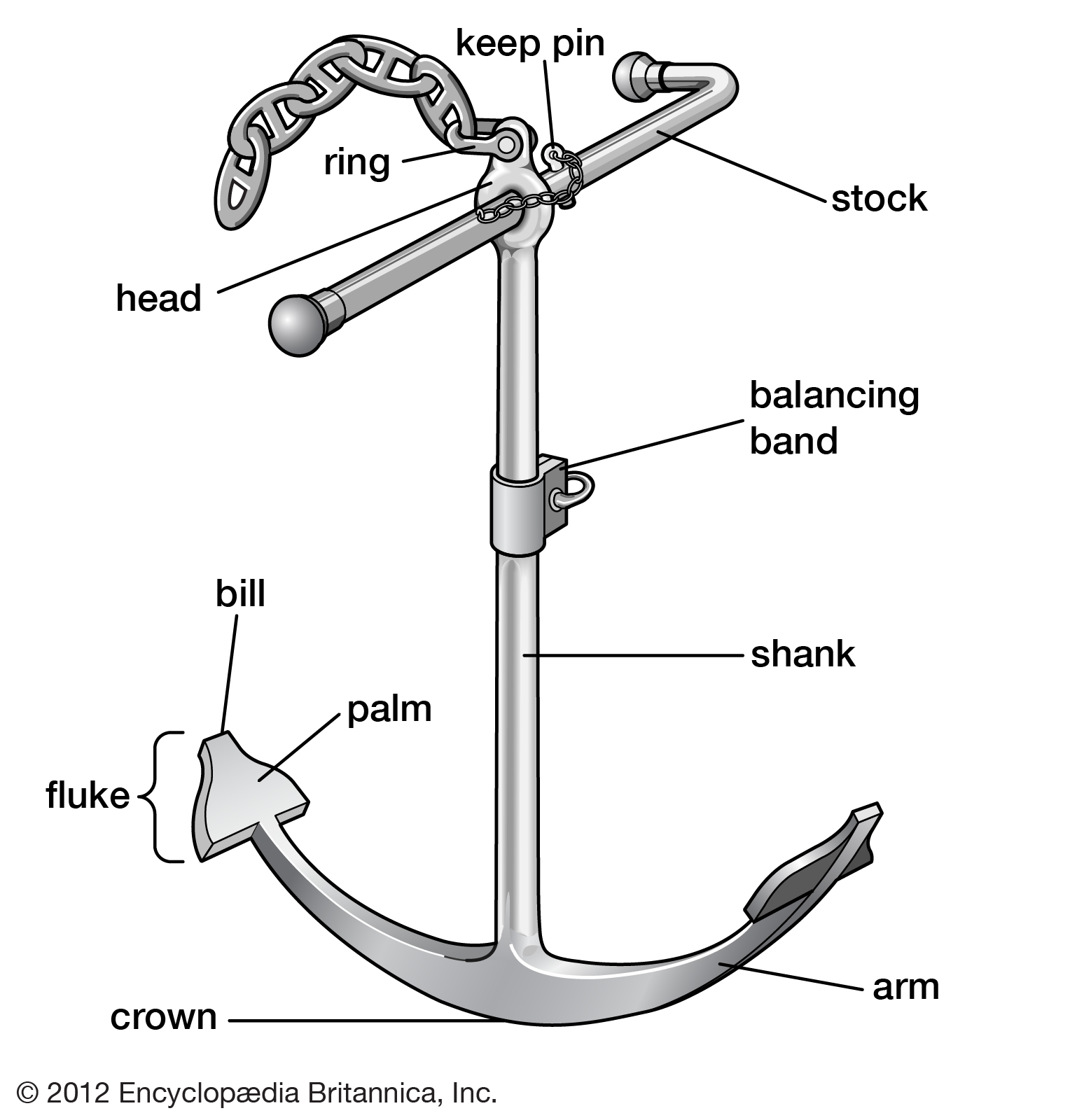
Ship anchor old type. Stock Anchor. Pic credit : Brittannica
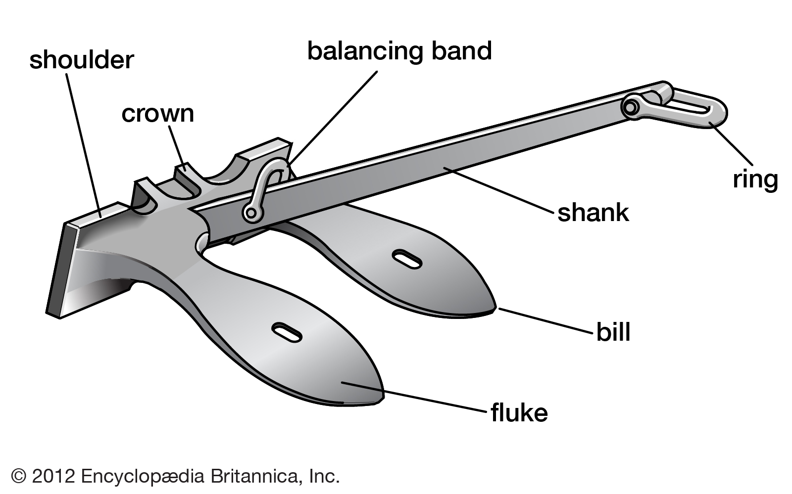
Stockless ship anchor. Pic credit : Brittannica
>> The modern ‘Bower stockless anchor’ is in existence since the days of steam propulsion and has been developed to suit the stowing arrangement in the hawse pipe of the ship and with a lower holding strength than the stock anchor.
>> The modern stockless anchor has a holding strength of five times its weight in Newtons, whereas the ancient or primitive stock anchor has a holding strength of ten times its weight in Newtons.
>> The reason for this requirement of lightness is that the anchor has to be hauled quickly (within 30 minutes maximum ), when the weather deteriorates during anchor stay and the ship has to haul up the anchor and proceed to sea. A stock anchor will take longer time to haul up and therefore endanger the safety of the ship.
>> In the worst condition it can lead to capsizing of the ship especially if it is in light condition or in the best condition drag anchor and run aground ashore. Whereas in a sailing ship the ship is normally anchored deep inside the natural harbour where the severity of the sea condition does not reach. It should be understood that the greater the holding force , the larger time required to haul up the anchor. The forces acting on a ship riding anchor is described as under.
Forces acting on the ship whilst riding anchor:-
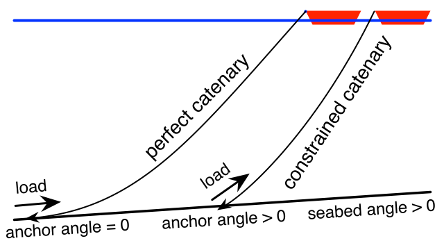
>> The chain connecting the anchor to the ship is of heavy construction with a breaking strength much higher than required . The chain links are made heavy so that when the anchor is dropped with the attached chain and the ship is in stand still condition, the catenary so formed is deep and almost vertical.
The shape of the curve formed by the chain is called a catenary. This curve is like a parabola but has a different mathematical formula when compared with the parabola. It is a physical curve caused by a hanging chain supported at the ends and the total depth of the curve from the end supports is directly proportional to the unit length of the chain.
>> The Bower anchor is made of two parts ,
1. The head (crown) with shoulder and the flukes folded inwards
2. The shank .
>> Both these parts are fitted together by a heavy and large pin fitted tightly on the head but loosely in the shank hole. The head has sufficient internal space to allow free movement of the shank to turn through about 150 on either side of the vertical, so that when it hits the ground it is not stable and can fall on either side of the vertical position.
>> When the anchor is released at the time of anchoring it drops by gravity taking along with it the chain. The anchor head being curved and not flat causes the anchor to fall on either side with the shaft resting on the ground and taking a posture like a plough entering the ground and thus gets fixed in the earth or ground. The details of the forces acting on the ship when riding anchor are given in the sketch shown as under.
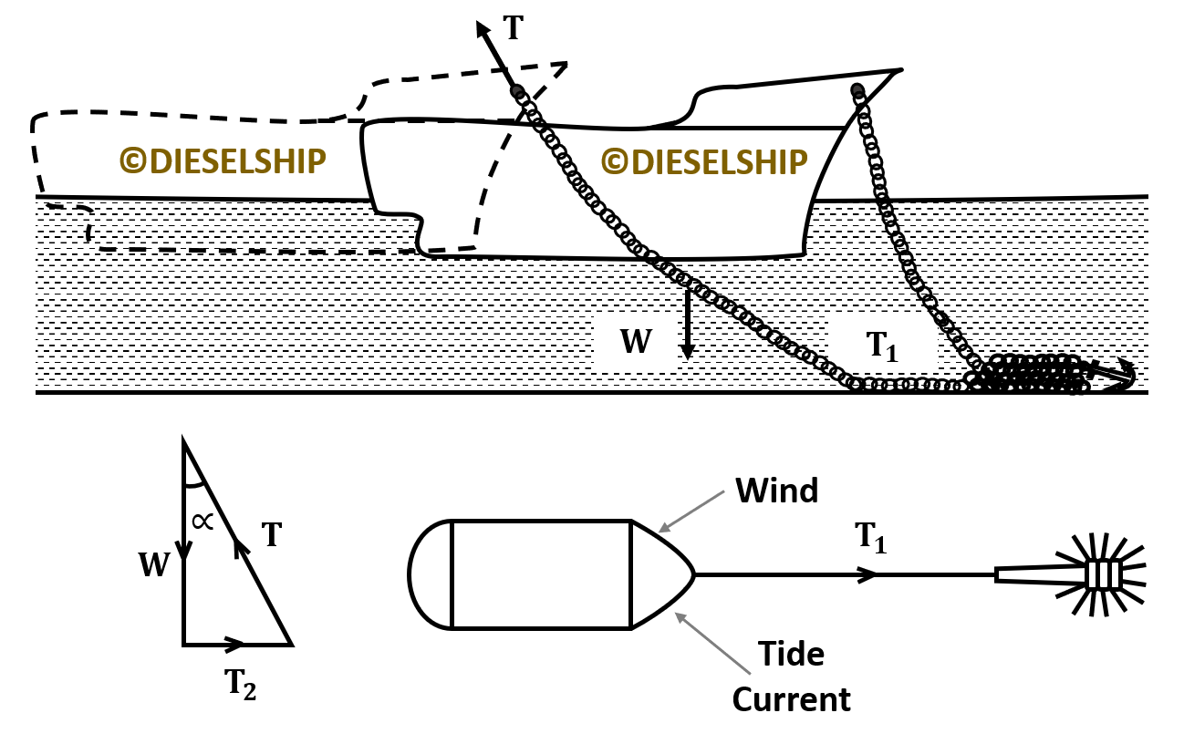
T= the total tension acting at the hawse pipe exit and is resisted by the ship’s buoyancy (has a very small trimming effect at forward) .
W = the weight of the length of chain forming the catenary ( length of chain from ground at point where the chain makes contact with the ground up to the hawse pipe mouth).
T1 = The horizontal tension at ground.
>> This horizontal tension T1 is the vector sum of the current and wind force. This is how the ship is moored and drift prevented. Hence the anchor resists the wind and tide. The ship is always facing the combined wind and tide in normal times.
>> When a medium sized ship anchors about 5 shackles are paid out. Assuming that the ship has anchored at slack water, there may be only 2 shackles forming the catenary.
A shackle is a unit of length and equal to 15 fathoms or 90 feet and is the standard length of a chain .
>> In this condition the weight of 2 shackles is able to moor the ship. As the tide builds up the ship drifts aft picking up about two more shackles making the length of the catenary now to 4 shackles. In this condition the weight of the anchor together with the weight of one shackle of chain is greater than the horizontal component of the weight of the 4 shackles of chain forming the catenary . This is explained mathematically as follows;
T1 = W Tan
>> Where W is the vertical angle . For all angles below 450 ‘W’ will be greater than T1 and hence the ship has a reserve force or strength of the weight of the anchor and one chain shackle in this condition.
>> Now if for some reason the weather deteriorates and both the current and wind force increase the remaining shackle will be lifted out of the water and further deterioration in the weather may make the catenary degenerate into a straight line . This is the limiting condition when the vertical angle exceeds 450 and the horizontal tension becomes larger than the weight of the anchor leading to the condition of anchor dragging.
>> During anchor stations some captains ask their C/O’s “How is the anchor leading.”. the C/O’s reply is normally 5 to 10 degrees to the vertical at slack water gives confidence to the captain that there is sufficient chain in the water to take care of stronger currents.
Anchor material and testing
>> Most of the modern anchors for large ships are now made of cast steel so that they are tough and can resist shock loading and breakage especially if the anchor strikes a rock or rocky surface whilst anchoring.
>> About 100 years back all anchors were made of cast iron and the method of testing them were by dropping them on hard prepared ground from a height of 75 feet. If it survives this test without breaking or cracking, it was sent to the ship and if it cracked or broke it went back to the foundry for recasting. This is destructive testing and not used now.
>> Modern anchors are subjected to non-destructive testing and the procedure is as follows.
Non-destructive testing of ship anchor
>> The anchor is placed on the test bed of a chain testing machine. The shank end is connected to either the fixed end of the machine and the head is connected to the ram end of the machine which moves inwards by hydraulic pressure .
>> The pressure is monitored on the pressure gauge fitted to the hydraulic cylinder. The required proof load is given by P* machine constant in tons or KN as required.
>> The arrangement is sketched below. The proof load is kept for 30-60 minutes as per class regulations and any deformity in shape of flukes or any crack formation is to be observed before approving the anchor.
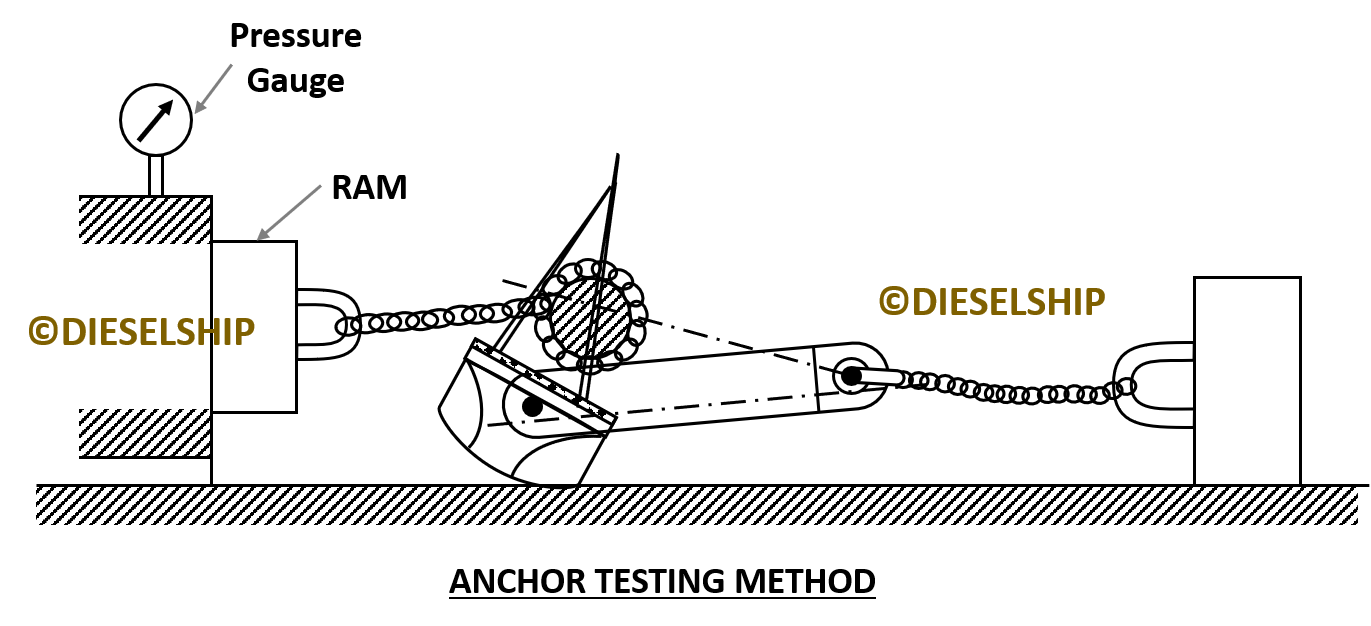
ANCHOR TESTING METHOD
Can a old anchor from scrap yard be used as replacement anchor?
>> An old anchor obtained from a ship scrap yard can be used as a replacement anchor provided the following conditions are met:
- The selected anchor conforms to the mass requirement as per the equipment letter
- The general inspection reveals no
- The anchor is to be subjected to a proof load test as per the proof load given in the tables and witnessed by the class The testing machine should be approved by class.
Anchor Proof load test table
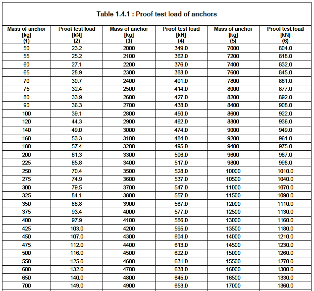
Anchor Proof Load Table
Classification rules on Anchors and Chains
>> The Anchor & Anchoring equipment is therefore not designed to hold a ship off fully exposed coasts in rough weather or to stop a ship which is moving or drifting. In this condition the loads on the anchoring equipment increase to such an extent that its components may be damaged or lost due to the high energy forces generated particularly in large ships.
>> The anchoring equipment presently required herewith is designed to hold a ship in good holding ground in conditions such as to avoid dragging of the anchor. In poor holding ground the holding power of the anchors will be significantly reduced.
>> A good holding ground as defined by the above stated requirements are;
- A current speed of not more than 5 m/sec (max tide current speed)
- A wind speed of not more than 25m/sec
- Depth of water ranging between 85M and 100M .
- The ground should be sandy or muddy and not rocky
>> A good anchoring ground is normally marked on the chart by an anchor symbol on hydro-graphic charts giving details of port anchorages.
>> The length of chain provided varies between 86 M to 770 M depending on the size and dimensions of the ship.
>> To find the equipment details for anchors and chains as given in the rigging tables of the classification rules, the following procedure is adopted.
Equipment number
The equipment number, EN, on which the requirements of equipment are based is to be calculated as follows :-
EN = K * ENc
where,
ENc = Δ2/3 + 2BH + 0.1A
Δ = moulded displacement, [t], to the summer load water line
A = area [m2] in profile view of the hull, superstructures and houses above the summer load waterline, which is within the Rule length of the vessel. Houses of breadth less than B/4 are to be disregarded.
H = effective height, [m], from the summer load waterline to the top of the uppermost deckhouse, to be measured as follows:
H = a + Σhi
a = distance [m] from summer load waterline amidships to the upper deck at side
hi = height [m] on the centre line of each tier of houses having a breadth greater than B/4. For lowest tier, hi is to be measured at centre line from upper deck, or from a notional deck line where there is a local discontinuity in the uppers deck.
Calculation notes
>> In the calculation of H and A, sheer and trim are to be ignored.
>> Parts of windscreens or bulwarks which are more than 1.5[m] in height are to be regarded as parts of houses when determining H and A. The height of the hatch coamings and that of any deck cargo, such as containers, may be disregarded.
>> ‘K’ is a factor depending upon the type of vessel and service notation as given below: For fishing vessels,
K = 1.00
For other vessels,
K = 1.00 for vessels of Unrestricted Service.
K = 0.85 for vessels of Coastal Service
>> Having found the equipment numeral, the details regarding sizes and quality may be obtained from the rigging tables provided in these regulations.
>> The equipment numeral is also given in the class certificate and hence there is no need to refer to this formula to find the equipment numeral whenever there is a need as in the case of ordering new chain lengths when old chain lengths have been worn beyond the rule requirement.
>> For information and guidance a specimen of the Rigging table is reproduced as under.
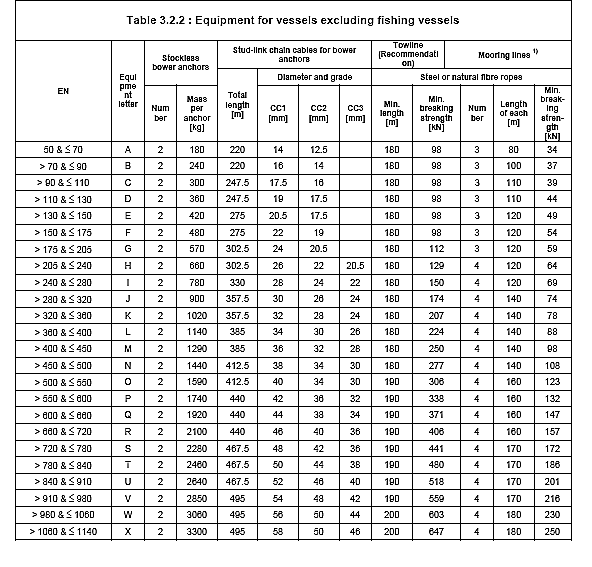
Rigging table
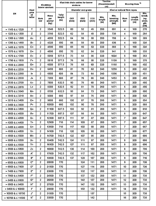
Rigging table
How to use rigging table?
>> As an example let us consider the group EN 2380 to EN2530. The corresponding equipment letter is J+, each anchor weighs 7.35 tons and the total length of chains provided is 605 meters.
>> The chains always come in lengths of a unit “shackle” , where 1 shackle is 15 fathoms or 90 feet. The shackle is an English unit and all chain manufacturers make chains in one shackle length. The rule length is therefore increased to the nearest full shackle length to meet the rule requirement .
>> For ease of operation the total length of 605 meters will be divided into two equal halves and the nearest minimum full chain length in shackles per chain is given by 605/2*3.7878/90=12.73 shackles. The nearest full shackle length is 13 shackles. Hence each anchor will be connected to 13 shackle lengths of chain to make up for the rule length of chain.
>> As per the classification rules the ship has to be provided one spare shackle of chain. This spare shackle is therefore connected to one of the chains as that is the most convenient way of stowing the spare chain length. If it is kept in the forecastle stores, it will occupy all the space and make it difficult to stow spare mooring ropes and wires.
>> Hence on most ships either the port or starboard chain is longer by one shackle and that extra length is accounted for the spare shackle length. The shackle length is connected to the next shackle length by a ‘Kenter “ shackle which is specially designed to fit in the cable lifter link slots, and also be capable of being opened and joined.
Anchor chain links
The link is called a stud link and is different from an ordinary chain link.
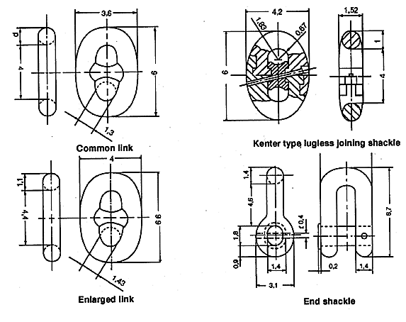
Anchor Chain links
>> The sketch(Anchor chain links) of two stud links , one a common link and the other an enlarged link, a kenter shackle and an ordinary shackle are reproduced here to understand their uses.
>> The ordinary shackle is used to join the anchor at the anchor end and the chain in the chain locker connecting it to the bulkhead stiffener. The kenter shackle connects one chain length to another chain length and the stud links are of two standards one common size and the other enlarged link for larger vessels..
Grades of chain link
>> The chain links are graded according to the carbon content in the steel and corresponding heat treatment and the three standards of link material are graded as CC1, CC2, and CC3. The three standards are graded as follows :
CC1———— low strength.
CC2———–medium strength.
CC3———–high strength.
>> Owners are free to choose any grade of steel from the given three qualities. Having selected a grade the same grade is to be used throughout the chain length for the full life span of the ship, since the cable lifter slots are made as per the diameter according to the grade selected.
Anchor chain stowage and connections
>> The chains are stowed in two separate chain wells placed in the chain locker forming part of the forepeak tank. The chain is led out of the locker through a pipe with a bell mouth at the inner end of the spurling pipe.
>> This bell mouthing is provided to enable the chain to move in a rotating fashion as it is being stowed while heaving up the anchor. This rotating motion enables the chain to be stowed properly without forming a heap.
>> The chain passes out of the spurling pipe wraps on the cable lifter and enters the hawse pipe where it is connected to the anchor.
>> The reason why stud link is used is it reduces free movement of the links within the chain locker and thereby prevents “ kinking” of the links. When kinking happens the free flow of the chain is prevented by a lump of chain getting stuck at the bell mouthing preventing free flow of the chain.
Anchor end of the chain
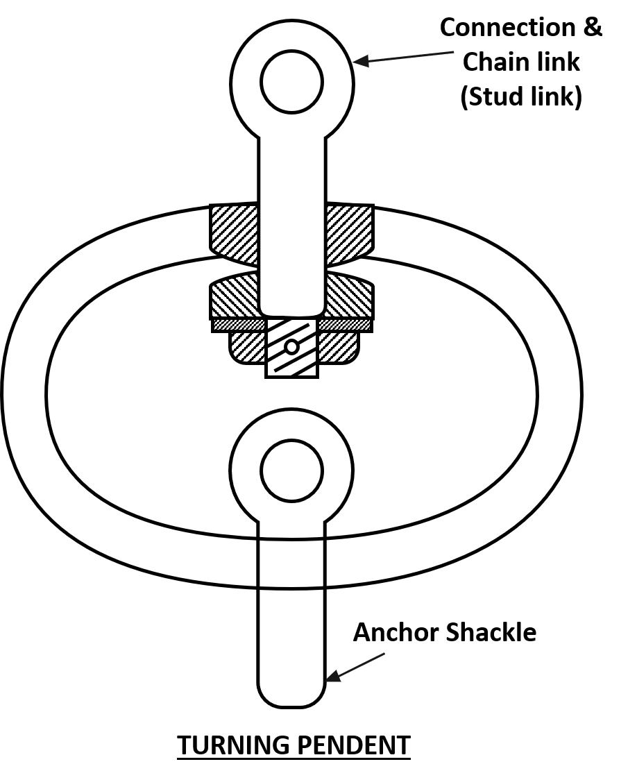
At the anchor end a turning pendent is connected between the anchor and the connecting shackle. This turning pendent is provided to allow free rotation of the anchor when it is lifted out of the water without allowing the chain to twist.
This rotation occurs after long anchorage stay. In a day , whilst at anchor the ship drifts through one circle around the anchor caused by high and low water. The anchor chain gets twisted by one turn. If the ship is at anchor for 10 days it gets twisted by 10 turns. when the anchor gets lifted out of the water, the stored twist energy in the chain is released causing the chain to unwind along with the anchor. The anchor being heavy will gain high rotational momentum and hence will continue turning even after the chain has straightened and that will hinder hauling the chain through the hawse pipe. To free the chain from this rotational movement this pendent is fitted. The sketch of the pendent is given under.
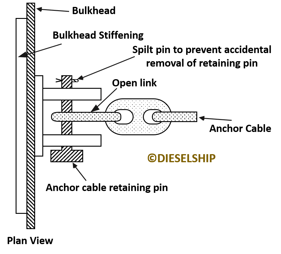
Bitter end of the anchor chain
>> The inboard end of a ship anchoring cable which is secured in the chain locker by the clench pin is called the bitter end of anchor cable.
>> In an emergency especially when the weather turns bad and operation of the windlass is not possible, either because the windlass is defective or the entry to forecastle deck is not possible, the chain can be made to run out by dismantling the joining shackle in the chain locker, and releasing the windlass brake.. A marker buoy is attached to the chain so that the chain and anchor can be recovered later.
>> Provision is to be made for securing the bitter end of the chain cable to the ship structure. The fastening for securing the bitter end is to be capable of withstanding a force of not less than 15% and not greater than 30% of the minimum breaking strength of the as fitted chain cable.
>> It is to be provided with suitable means such that, in case of emergency, the chain cable may be easily slipped to sea from an accessible position outside the chain cable locker. Where the mechanism for slipping the chain cable to sea penetrates the chain locker bulkhead, this penetration is to be made watertight.
>> Bitter end should be capable of holding the chain weight, but it should be constructed so that, it will break incase of emergency so it doesn’t damage the ship structure. As mentioned above, there has to be a provision outside the chain locker which will release the bitter end of the chain in case of any emergency and the anchor and chain is to be released to the sea.
>> Alternatively the cable end connection may be accepted where it has been designed and constructed to a recognised National or International Standard.
>> The cable clench supporting structure is to be adequately stiffened in accordance with the breaking strength of the fastening provided.
My father has a 900 pound anchor that we are donating to American Legion . How can. It be identified? Is there any way you could can suggest how we might find information on such an anchor it has the stud link and anchor shackle shown in your diagram. Thank you Sincerely Kevin Blanchard
How can I choose bow anchor or stern anchor is suiltable for a 60 meter planning craft, please give me answers.
Me dearly departed Darr t’was a Ship’s Captain whose nickname t’was “2 Shackles Bill”. Aye always thort his nick name t’was ter dee with his “Mort Dock & Niagra Falls”, but now after read’in yer tale of Ship Anchor’in Practices aye can see wot it t’was all aboot. Cheers
What is speed of heaving up anchor.how many meter per min can heave up
Excellent article, useful to student community in shipping industry.