WO2017017949A1 - Radiation-emitting device - Google Patents
Radiation-emitting device Download PDFInfo
- Publication number
- WO2017017949A1 WO2017017949A1 PCT/JP2016/003454 JP2016003454W WO2017017949A1 WO 2017017949 A1 WO2017017949 A1 WO 2017017949A1 JP 2016003454 W JP2016003454 W JP 2016003454W WO 2017017949 A1 WO2017017949 A1 WO 2017017949A1
- Authority
- WO
- WIPO (PCT)
- Prior art keywords
- arm
- radiation
- rotation
- unit
- radiation source
- Prior art date
Links
Images


Classifications
-
- A—HUMAN NECESSITIES
- A61—MEDICAL OR VETERINARY SCIENCE; HYGIENE
- A61B—DIAGNOSIS; SURGERY; IDENTIFICATION
- A61B6/00—Apparatus for radiation diagnosis, e.g. combined with radiation therapy equipment
- A61B6/44—Constructional features of apparatus for radiation diagnosis
- A61B6/4429—Constructional features of apparatus for radiation diagnosis related to the mounting of source units and detector units
- A61B6/4458—Constructional features of apparatus for radiation diagnosis related to the mounting of source units and detector units the source unit or the detector unit being attached to robotic arms
-
- A—HUMAN NECESSITIES
- A61—MEDICAL OR VETERINARY SCIENCE; HYGIENE
- A61B—DIAGNOSIS; SURGERY; IDENTIFICATION
- A61B6/00—Apparatus for radiation diagnosis, e.g. combined with radiation therapy equipment
- A61B6/42—Apparatus for radiation diagnosis, e.g. combined with radiation therapy equipment with arrangements for detecting radiation specially adapted for radiation diagnosis
- A61B6/4283—Apparatus for radiation diagnosis, e.g. combined with radiation therapy equipment with arrangements for detecting radiation specially adapted for radiation diagnosis characterised by a detector unit being housed in a cassette
-
- A—HUMAN NECESSITIES
- A61—MEDICAL OR VETERINARY SCIENCE; HYGIENE
- A61B—DIAGNOSIS; SURGERY; IDENTIFICATION
- A61B6/00—Apparatus for radiation diagnosis, e.g. combined with radiation therapy equipment
-
- A—HUMAN NECESSITIES
- A61—MEDICAL OR VETERINARY SCIENCE; HYGIENE
- A61B—DIAGNOSIS; SURGERY; IDENTIFICATION
- A61B6/00—Apparatus for radiation diagnosis, e.g. combined with radiation therapy equipment
- A61B6/10—Application or adaptation of safety means
-
- A—HUMAN NECESSITIES
- A61—MEDICAL OR VETERINARY SCIENCE; HYGIENE
- A61B—DIAGNOSIS; SURGERY; IDENTIFICATION
- A61B6/00—Apparatus for radiation diagnosis, e.g. combined with radiation therapy equipment
- A61B6/10—Application or adaptation of safety means
- A61B6/102—Protection against mechanical damage, e.g. anti-collision devices
- A61B6/105—Braking or locking devices
-
- A—HUMAN NECESSITIES
- A61—MEDICAL OR VETERINARY SCIENCE; HYGIENE
- A61B—DIAGNOSIS; SURGERY; IDENTIFICATION
- A61B6/00—Apparatus for radiation diagnosis, e.g. combined with radiation therapy equipment
- A61B6/42—Apparatus for radiation diagnosis, e.g. combined with radiation therapy equipment with arrangements for detecting radiation specially adapted for radiation diagnosis
- A61B6/4208—Apparatus for radiation diagnosis, e.g. combined with radiation therapy equipment with arrangements for detecting radiation specially adapted for radiation diagnosis characterised by using a particular type of detector
-
- A—HUMAN NECESSITIES
- A61—MEDICAL OR VETERINARY SCIENCE; HYGIENE
- A61B—DIAGNOSIS; SURGERY; IDENTIFICATION
- A61B6/00—Apparatus for radiation diagnosis, e.g. combined with radiation therapy equipment
- A61B6/44—Constructional features of apparatus for radiation diagnosis
-
- A—HUMAN NECESSITIES
- A61—MEDICAL OR VETERINARY SCIENCE; HYGIENE
- A61B—DIAGNOSIS; SURGERY; IDENTIFICATION
- A61B6/00—Apparatus for radiation diagnosis, e.g. combined with radiation therapy equipment
- A61B6/44—Constructional features of apparatus for radiation diagnosis
- A61B6/4405—Constructional features of apparatus for radiation diagnosis the apparatus being movable or portable, e.g. handheld or mounted on a trolley
-
- A—HUMAN NECESSITIES
- A61—MEDICAL OR VETERINARY SCIENCE; HYGIENE
- A61B—DIAGNOSIS; SURGERY; IDENTIFICATION
- A61B6/00—Apparatus for radiation diagnosis, e.g. combined with radiation therapy equipment
- A61B6/44—Constructional features of apparatus for radiation diagnosis
- A61B6/4429—Constructional features of apparatus for radiation diagnosis related to the mounting of source units and detector units
- A61B6/4452—Constructional features of apparatus for radiation diagnosis related to the mounting of source units and detector units the source unit and the detector unit being able to move relative to each other
-
- A—HUMAN NECESSITIES
- A61—MEDICAL OR VETERINARY SCIENCE; HYGIENE
- A61B—DIAGNOSIS; SURGERY; IDENTIFICATION
- A61B6/00—Apparatus for radiation diagnosis, e.g. combined with radiation therapy equipment
- A61B6/46—Apparatus for radiation diagnosis, e.g. combined with radiation therapy equipment with special arrangements for interfacing with the operator or the patient
- A61B6/461—Displaying means of special interest
- A61B6/462—Displaying means of special interest characterised by constructional features of the display
-
- A—HUMAN NECESSITIES
- A61—MEDICAL OR VETERINARY SCIENCE; HYGIENE
- A61B—DIAGNOSIS; SURGERY; IDENTIFICATION
- A61B6/00—Apparatus for radiation diagnosis, e.g. combined with radiation therapy equipment
- A61B6/54—Control of apparatus or devices for radiation diagnosis
-
- A—HUMAN NECESSITIES
- A61—MEDICAL OR VETERINARY SCIENCE; HYGIENE
- A61B—DIAGNOSIS; SURGERY; IDENTIFICATION
- A61B6/00—Apparatus for radiation diagnosis, e.g. combined with radiation therapy equipment
- A61B6/40—Apparatus for radiation diagnosis, e.g. combined with radiation therapy equipment with arrangements for generating radiation specially adapted for radiation diagnosis
Definitions
- the present invention relates to a radiation irradiation apparatus that irradiates a subject with radiation when acquiring a radiation image of the subject.
- Patent Document 1 Conventionally, for example, as disclosed in Patent Document 1 and Non-Patent Document 1, only the minimum components for radiation irradiation, such as a radiation source and an electric circuit, are mounted and can be operated by an operator by hand.
- a portable radiation irradiation apparatus has been proposed. This type of portable radiation irradiation apparatus is light enough to be held and operated by an operator, and is advantageous for imaging a subject from various directions.
- a radiation detector that normally records a radiographic image representing the subject by irradiation with radiation that has passed through the subject.
- a radiation detector a cassette type radiation detector in which a control device such as an image detection unit, a driving battery, and an electric circuit related to driving is housed in a housing is well known. Then, if such a radiation detector is disposed at a position facing the radiation irradiation apparatus with the subject interposed therebetween, and the radiation irradiation apparatus is driven in this state, the radiation transmitted through the subject is detected by the radiation detector. A radiographic image represented by radiation that has been irradiated to the subject and transmitted through the subject is acquired.
- the portable radiation irradiation apparatus can be operated by being held by the operator's hand. However, in order to prevent camera shake and further exposure to the operator's hand, etc., a line having a radiation source is used.
- a radiation irradiation apparatus including a support device that supports a source unit has been proposed.
- Non-Patent Document 1 also shows an example of such a support device, and in particular, a support device that can travel by providing a wheel portion at the lower portion of a support leg.
- the radiation irradiation apparatus provided with such a support apparatus basically accommodates a control unit including a leg portion that can be traveled by wheels, a battery for driving the radiation source, an electric circuit for driving the radiation source, and the like.
- the main body portion is held on the leg portion, and the arm portion is connected to the main body portion, and the radiation source portion is attached to the tip of the arm portion.
- an arm section configured to be movable up and down and foldable with respect to the main body of the apparatus.
- the arm part is attached to the apparatus main body by an elevating mechanism having a rotating part.
- the arm portion is composed of a first arm to which the radiation source portion is attached and a second arm attached to the device main body by a lifting mechanism having a rotating portion. It is configured to be movably mounted.
- the lifting mechanism when not in use, the lifting mechanism is moved to the lowest position, and the second arm is rotated upward along the main body. Further, when the second arm is lifted by the lifting mechanism during use, the second arm rotates so that the radiation source part is separated from the main body, and the radiation source part is moved to the use position while maintaining the height of the radiation source part. It is designed to move. Moreover, the height of the radiation source part can be adjusted manually.
- the first arm is rotated with respect to the second arm and the second arm is moved with respect to the lifting mechanism regardless of the height of the second arm. The source portion can be moved to a desired position.
- the radiation irradiation apparatus When using such a radiation irradiation apparatus, first, the radiation irradiation apparatus is moved close to the patient's bed. At this time, the arm is moved to the lowest position and folded so as not to collide with various devices in the hospital room.
- the radiation source unit In use, the radiation source unit is moved to a desired position above the subject by raising the arm unit and rotating the arm unit to extend.
- the radiation detector is moved to a desired position behind the subject. In this state, the radiation source is driven to irradiate the subject with radiation, and the radiation transmitted through the subject is detected by the radiation detector to acquire a radiation image of the subject.
- the location of the device itself so that the radiation source unit does not collide with the bed or the like.
- the space near the bed may be narrow, and the device moved near the bed may not be easily moved.
- the present invention has been made in view of the above circumstances, and in a radiation irradiation apparatus, it is possible to prevent a collision of a radiation source portion with a bed or the like and to easily move the radiation source portion to a desired position. Objective.
- the radiation irradiation apparatus includes a leg portion capable of traveling on the apparatus mounting surface, A radiation source for irradiating the subject with radiation; An arm for supporting the radiation source, An arm support that is erected on the leg and supports the arm; An elevating mechanism for elevating and lowering the arm part relative to the arm support part, The arm unit rotates the first arm, the second arm, the first rotating unit that rotatably connects the first arm and the second arm, and the second arm and the lifting mechanism connected to the radiation source unit.
- a second rotating part that is movably connected;
- the arm portion When the arm portion is located at a position other than the first position raised or lowered by the elevating mechanism, it further comprises a restricting means for restricting rotation of the second arm from the initial rotation position by the second rotation portion. It is what.
- the arm unit includes a first arm coupled to the radiation source unit, a second arm, a first pivot unit that pivotably couples the first arm and the second arm, and a second arm. It has the 2nd rotation part which connects a raising-lowering mechanism so that rotation is possible. For this reason, the arm portion can be folded or extended by rotating the first arm with respect to the second arm and rotating the second arm with respect to the lifting mechanism.
- “Initial rotation position” refers to the rotation of the arm when the first arm and the second arm are folded, preferably the first arm and the second arm are folded to a limit at which they no longer rotate. It means moving position.
- the rotation position of the part may be the initial rotation position.
- the rotation position may be the initial rotation position.
- to rotate the second arm upward means to rotate the first rotating part so as to be positioned above the second rotating part.
- to rotate the second arm downward means to rotate the first rotating part so as to be positioned below the second rotating part.
- “To restrict the rotation of the second arm” means that the second arm cannot be rotated by the second rotation unit.
- the direction in which the rotation is restricted may be only one direction around the rotation axis, or may be both directions.
- the rotation direction in the case where the second arm is rotated downward from the state where the second arm is rotated downward is defined as the first rotation direction
- the first rotation direction of the second arm in the present invention, in the first rotation direction of the second arm. It is preferable to restrict the rotation.
- the first rotation direction is the second arm It becomes a direction to turn to the support part side.
- the rotation in the second rotation direction which is the rotation direction opposite to the first rotation direction, may be restricted.
- the initial rotation position is the position where the second arm is rotated upward
- the restricting means may be configured to restrict the rotation of the second arm toward the arm support portion by the second rotating portion.
- the restricting means may release the restriction of the rotation of the second arm toward the arm support part by the second rotating part.
- the regulating means may be composed of a surface of the arm support portion on the side where the arm portion is supported.
- the first position may be the highest position in the lifting / lowering range of the arm portion by the lifting / lowering mechanism.
- the arm support part may be a main body part including a control means for controlling the radiation source part.
- Control means means means for controlling generation and irradiation of radiation such as tube current, irradiation time and tube voltage, for example, a computer installed with a control program, dedicated hardware, or A combination of both.
- the arm portion may be supported by the arm support portion so as to be pivotable.
- the arm support part is erected on the leg part.
- “Swivel” means rotation around the axis when the axis extending in the direction in which the arm support portion is erected is defined.
- the radiation irradiation apparatus may further include a first rotation part restricting means for restricting the rotation of the first rotation part.
- the radiation irradiation apparatus may further include display means for displaying the movable range of the arm part and the radiation source part when the arm part is viewed from the side.
- the display means may display the target position of the radiation source part in a state where the arm part is viewed from the side.
- “Side” means a direction parallel to the rotation axis of the first rotation unit or the second rotation unit.
- Target position means a position where an imaging unit should be arranged when imaging a subject. Specifically, it is a position where the subject can be appropriately imaged, and the target position can be determined based on the imaging conditions set based on the imaging request information, for example.
- the rotation of the second arm from the initial rotation position by the second rotation portion is restricted. For this reason, it can prevent that an arm part and a radiation source part move, and collide with a subject, a bed, etc.
- the rotation of the second arm is not restricted, so that the arm unit and the radiation source unit can be moved while avoiding the subject and the bed. . Therefore, according to the present invention, the radiation source part can be easily moved to a desired position.
- the perspective view which shows the whole shape of the radiation irradiation apparatus by embodiment of this invention The figure which shows the state at the time of use of the radiation irradiation apparatus of embodiment of this invention
- a direction arrow view of FIG. Side view showing the configuration of the lifting mechanism
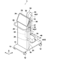
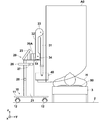
- FIG. 1 is a perspective view showing an overall shape of a radiation irradiation apparatus according to an embodiment of the present invention when not in use
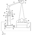
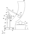
- FIG. 2 is a side view showing a state when the radiation irradiation apparatus according to the embodiment of the present invention is in use.
- the upper and lower sides in the vertical direction are referred to as “upper” and “lower”, respectively, and the same state
- a coordinate system is set in which the vertical direction is the z direction, the horizontal direction in FIG. 2 is the y direction, and the direction perpendicular to the paper surface in FIG.
- the radiation irradiation apparatus 1 includes a leg portion 10, a main body portion 20, an arm portion 30, and a radiation source portion 40.
- the leg portion 10 can travel on the device mounting surface 2 and has a plate-like pedestal 11 and four wheel portions 12 attached to the four corners of the lower surface of the pedestal 11.
- the wheel portion 12 is made of a rubber tire or the like, and is attached to the pedestal 11 so as to be rotatable in a horizontal plane around an axis extending in the vertical direction. Thereby, the leg part 10 can be run on the apparatus mounting surface 2 in an arbitrary direction.
- the main body 20 is erected on the leg 10 and includes a housing 21.
- a control device that controls driving of the radiation irradiation device 1 and a battery (hereinafter simply referred to as a control device 22) are housed.
- the control device 22 controls the generation and irradiation of radiation such as tube current, irradiation time and tube voltage in the radiation source unit 40, and control related to acquisition of radiation images such as image processing on the radiation image acquired by the radiation detector 80. It is a device for performing.
- the control device 22 is configured by, for example, a computer in which a control program is installed, dedicated hardware, or a combination of both.
- a monitor 23 is attached to the upper surface of the casing 21.
- a handle 26 for pushing and pulling the radiation irradiating apparatus 1 is attached to the upper portion of the housing 21 by an adapter 27.
- omnidirectional cameras 28 for taking omnidirectional images of the apparatus 1 are attached to both side surfaces of the main body 20. In FIGS. 1 and 2, only one omnidirectional camera 28 is shown.
- the monitor 23 is composed of a liquid crystal panel or the like, and displays a radiographic image acquired by imaging the subject H and various information necessary for controlling the apparatus 1.
- the monitor 23 includes a touch panel type input unit 24 and receives input of various instructions necessary for the operation of the apparatus 1. Specifically, an input for setting imaging conditions and an input for imaging, that is, radiation emission are accepted.
- the monitor 23 corresponds to display means.
- the monitor 23 is attached to the upper surface of the main body 20 so that the tilt and rotation position can be changed. Further, instead of the touch panel type input unit 24, buttons or the like for performing various operations may be provided as the input unit 24.
- the arm part 30 is supported by the main body part 20. Specifically, the arm portion 30 is supported on the surface of the main body portion 20 opposite to the handle 26, that is, the right surface 20A in FIG. For this reason, in this embodiment, the main-body part 20 comprises the arm support part by this invention.
- the arm unit 30 can be moved up and down with respect to the main body unit 20 by the lifting mechanism 50.
- the arm unit 30 includes a first arm 31, a second arm 32, a first rotation unit 33, a second rotation unit 34, and an attachment unit 35.
- the radiation source section 40 is connected to the tip of the first arm 31 by a mounting section 35.
- the end on the radiation source 40 side of the first arm 31 is the upper end
- the end on the second arm 32 is the lower end.
- an end portion on the first arm 31 side of the second arm 32 is an upper end portion and an end portion on the main body portion 20 side is a lower end portion.
- the first arm 31 and the second arm 32 are connected by a first rotation part 33 so as to be rotatable around a rotation axis AX1.
- the rotation axis AX1 is an axis extending in the x direction.
- the first arm 31 rotates about the rotation axis AX1 so that the angle formed with the second arm 32 is changed.
- the first rotation unit 33 holds both the first arm 31 and the second arm 32 so that the first arm 31 rotates through a friction mechanism. Therefore, the first arm 31 can be rotated by applying a strong external force to some extent, and does not rotate unless an external force is applied, and maintains a relative angle with respect to the second arm 32.
- the second arm 32 is connected to the adapter 51 attached to the upper end portion of the lifting mechanism 50 via the second rotation portion 34 so as to be rotatable around the rotation axis AX2.
- the rotation axis AX2 is an axis extending in the x direction.
- the second arm 32 rotates about the rotation axis AX2 so that the angle formed with the surface 20A of the main body 20 on the side where the arm unit 30 is supported is changed.
- the second rotating part 34 holds both the arm 32 so that the second arm 32 rotates with respect to the main body part 20 via a friction mechanism. For this reason, the 2nd rotation part 34 can be rotated by applying a strong external force to some extent, does not rotate unless an external force is applied, and maintains the relative angle with respect to the main body part 20.
- FIG. 3 is a view taken in the direction of arrow A in FIG. As shown in FIG. 3, a groove 29 through which the adapter 51 can pass when the lifting mechanism 50 moves up and down is formed on the right side surface 20 ⁇ / b> A of the main body 20 in FIG. 2. In FIG. 3, the monitor 23 and the arm part 30 are omitted for the sake of explanation.
- the attachment portion 35 has a U shape and is attached to the tip of the first arm 31.
- the radiation source unit 40 is connected to the distal end of the first arm 31 via the attachment unit 35 so as to be rotatable around the rotation axis AX3.
- the rotation axis AX3 is an axis extending in the x direction.
- the radiation source section 40 rotates about the rotation axis AX3 so that the angle formed with the first arm 31 is changed.
- the attachment portion 35 holds both the radiation source portion 40 and the first arm 31 so as to rotate via a friction mechanism. For this reason, the radiation source unit 40 can be rotated by applying a strong external force to some extent, and does not rotate unless an external force is applied, and maintains a relative angle with respect to the first arm 31.
- the rotation between the first arm 31, the second arm 32, and the radiation source unit 40 is performed via a friction mechanism, but the rotation position may be fixed by a known lock mechanism. In this case, the rotation between the first arm 31, the second arm 32, and the radiation source unit 40 becomes possible by releasing the lock mechanism. Then, the rotation position can be fixed by locking the lock mechanism at the desired rotation position.
- the arm unit 30 is at the lowest position in the lifting mechanism 50. Further, the rotation position of the arm unit 30 is in the initial rotation position.
- the initial rotation position is a rotation position of the arm unit 30 when the first arm 31 and the second arm 32 are folded.
- Rotation position In the initial rotation position, the second arm 32 is rotated such that the first rotation part 33 is positioned above the second rotation part 34.
- the first arm 31 and the second arm 32 are connected by the connecting belt 36.
- one end of the connecting belt 36 is attached to the second arm 32, and a hook-and-loop fastener is attached to the other end.
- a hook-and-loop fastener corresponding to the hook-and-loop fastener of the connecting belt 36 is attached to the opposite surface of the first arm 31 in FIG.
- the connecting belt 36 is turned from the right side surface of the first arm 31 in FIG. 1 to the opposite side surface to connect the surface fastener of the connecting belt 36 and the surface fastener attached to the first arm 31.
- the first arm 31 does not rotate with respect to the second arm 32 in the initial rotation position.
- the connecting belt 36 corresponds to the first rotating portion regulating means.
- the radiation source unit 40 is configured by housing a radiation source, a collimator for narrowing the radiation irradiation range, and the like in a housing 41.
- the radiation source includes, for example, an X-ray tube, a booster circuit, a cooling unit that cools the X-ray tube, and the like. Radiation emission from the radiation source of the radiation source unit 40 is performed by an instruction from the input unit 24 of the monitor 23 by the operator.
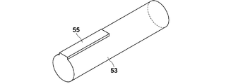
- the lifting mechanism 50 includes an outer cylinder 52 attached to the inside of the main body 20, a shaft 53 fitted to the outer cylinder 52, and an adapter 51 attached to the upper end portion of the shaft 53. Prepare. Note that a hole 56 is formed in the adapter 51 at a position that becomes the rotation axis AX ⁇ b> 2 of the second rotation portion 34.
- the shaft 53 is movable in the vertical direction with respect to the outer cylinder 52, and the vertical position of the shaft 53 with respect to the outer cylinder 52 can be fixed at a desired position by a lock mechanism (not shown). .
- a key groove 54 is formed on the outer cylinder 52, and a key 55 that engages with the key groove 54 is formed on the shaft 53.
- the key 55 is formed in a predetermined length from the upper end of the shaft 53.
- the key 55 has such a length that the lower end of the key 55 is positioned above the upper end of the outer cylinder 52 in a state where the shaft 53 has reached the highest position. For this reason, until the shaft 53 reaches the highest position, the key 55 engages with the key groove 54, so that the shaft 53 does not rotate around the central axis with respect to the outer cylinder 52.
- the key 55 is disengaged from the key groove 54, so that the shaft 53 can rotate with respect to the outer cylinder 52 around its central axis.
- the arm part 30 attached to the lifting mechanism 50 can turn with respect to the main body part 20.
- the turning means rotation around the axis of the shaft 53, that is, the z-axis that is the axis perpendicular to the device mounting surface 2.
- the key groove 54 of the outer cylinder 42 and the key 55 of the shaft 53 correspond to the turning restricting means.
- a radiation detector 80 is disposed under the subject H lying on the bed 3, and radiation emitted from the radiation source unit 40 (for example, X Line) is applied to the radiation detector 80 through the subject H.
- the radiation detector 80 and the radiation irradiation apparatus 1 are connected by wire or wirelessly. As a result, the radiation image of the subject H acquired by the radiation detector 80 is directly input to the apparatus 1.
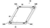
- FIG. 7 is an external perspective view of the radiation detector as seen from the front surface on the radiation irradiation side.
- the radiation detector 80 is a cassette-type radiation detector including a housing 82 that houses the image detection unit 81.
- the image detection unit 81 includes a scintillator (phosphor) that converts incident radiation into visible light, and a TFT (Thin Transistor) active matrix substrate.
- a scintillator phosphor
- TFT Thin Transistor
- the housing 82 has a gate driver that applies a gate pulse to the gate of the TFT to switch the TFT, and converts the electric charge accumulated in the pixel into an analog electric signal representing an X-ray image.
- An imaging control unit or the like having a signal processing circuit and the like for output is incorporated.
- the casing 82 has a size conforming to an international standard ISO (International Organization for Standardization) 4090: 2001, which is almost the same as, for example, a film cassette, an IP (Imaging Plate) cassette, or a CR (Computed Radiography) cassette. .
- Markers 84A to 84D representing identification information for identifying the radiation detector 80 are attached to the four corners of the front surface 82A of the housing 82.
- the markers 84A to 84D are each composed of two orthogonal barcodes.
- the radiation irradiation apparatus 1 is carried to the use position while running on the apparatus placement surface 2 such as a hospital floor by the wheel part 12 of the leg part 10 while being in the non-use state shown in FIG.
- the wheel portion 12 is attached to the pedestal 11 so as to be turnable as described above, the radiation irradiation apparatus 1 can be moved in the front-rear and left-right directions, and can be moved so as to be largely curved. It is also possible to turn on the spot. Therefore, it can be quickly brought to the use position in a state where a small turn is effective.
- the radiographic image is taken on the subject H lying on the bed 3 as shown in FIG.
- the radiation irradiation apparatus 1 When the radiation irradiation apparatus 1 is set near the subject H, the radiation irradiation apparatus 1 can be moved in the height direction of the subject H by the wheel portion 12. Thereby, the radiation irradiation apparatus 1 can be easily set in the optimal position.
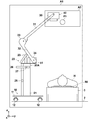
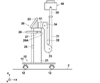
- 8 to 11 are schematic side views for explaining the operation of moving the arm unit 30 and the radiation source unit 40 in the radiation irradiation apparatus 1.
- 8 to 11 are side views of the device 1 as viewed in the x direction.
- 8 to 11 also show the movable range A0 of the arm part 30 and the radiation source part 40 viewed in the x direction.
- the arm unit 30 is at the lowest position by the lifting mechanism 50.
- the pivot position of the arm portion is at the initial pivot position described above.
- the state in which the arm unit 30 is at the lowest position by the elevating mechanism 50 and is in the above-described initial rotation position is defined as the initial position of the arm unit 30. As shown in FIG.
- the movable range A ⁇ b> 0 of the radiation source unit 40 overlaps the subject H and the bed 3 at the initial position of the arm unit 30. For this reason, when the second arm 32 rotates toward the main body 20, the radiation source 40 collides with the subject H and the bed 3.
- the second arm 32 when the arm unit 30 is not at the highest highest position in the lifting range that is lifted and lowered by the lifting mechanism 50, the second arm 32 is turned by the second turning unit 34 from the initial turning position. Is regulated. That is, when the second arm 32 is rotated toward the main body 20 around the rotation axis AX2, the second arm 32 collides with the surface 20A on the side where the arm 30 of the main body 20 is supported. When the arm unit 30 is at the lowest position, the second arm 32 cannot be rotated from the initial rotation state of the arm unit 30. For this reason, the second arm 32 cannot be rotated around the rotation axis AX2 to move the radiation source unit 40 upward. Note that the surface 20A on the side of the main body portion 20 on which the arm portion 30 is supported constitutes the regulating means of the present invention.
- FIG. 9 is a side view showing a state in which the arm portion 30 is raised to the highest position, which is the first position. In this state, the movable range A0 of the radiation source unit 40 overlaps the subject H.
- the arm portion 30 is at the highest position, if the second arm 32 is rotated about the rotation axis AX2 in the counterclockwise direction in the drawing from the initial rotation state, The two arms 32 do not collide with the surface 20A of the main body 20 on the side where the arm 30 is supported. For this reason, as shown in FIG.
- the second arm 32 can be rotated around the rotation axis AX ⁇ b> 2 beyond the main body 20.
- the radiation source unit 40 moves to the upper left side of the subject H, away from the subject H.
- the operator removes the connecting belt 36 and rotates the first arm 31 around the rotation axis AX1, thereby causing the radiation source to collide with the subject H and the bed 3 as shown in FIG.
- the part 40 can be moved further upward.
- the operator pulls the radiation source section 40 in the y direction to rotate the first arm 31 and the second arm 32 around the rotation axis AX1 and the rotation axis AX2, respectively.
- the radiation source unit 40 can be moved to the target position P1 directly above.
- the radiation source unit 40 is driven by an instruction from the input unit 24 to irradiate the subject H with radiation, and the radiation transmitted through the subject H is radiated.
- a radiation image of the subject H can be acquired by detection by the detector 80.
- the arm part 30 when the arm part 30 is in the first position raised by the lifting mechanism 50, that is, in a position other than the highest position, the initial rotation of the second arm 32 by the second rotating part 34 is performed.
- the rotation from the moving position is restricted.
- the arm part 30 and the radiation source part 40 do not move. Therefore, it is possible to prevent the arm unit 30 and the radiation source unit 40 from moving and colliding with the subject H and the bed 3 when the arm unit 30 is located at a position other than the highest position.
- the 2nd arm 32 when the arm part 30 exists in the highest position, the 2nd arm 32 can be rotated to the main-body part 20 side.
- the radiation source unit 40 can be easily moved to a desired position.
- the configuration of the device 1 can be simplified.
- connection belt 36 may restrict the first arm 31 from rotating with respect to the second arm 32 and moving the first arm 31 and the radiation source unit 40 away from the second arm 32. Therefore, it is possible to more reliably prevent the first arm 31 and the radiation source unit 40 from moving and colliding with the bed 3 of the subject H.
- the movable range A0 of the arm unit 30 and the radiation source unit 40 shown in FIGS. 8 to 11 may be displayed on the monitor 23.
- Sensors that respectively detect the second rotation angle that is the rotation angle of the two arms 32 are provided in the arm unit 30.
- the omnidirectional camera 28 captures an image of the entire periphery of the apparatus 1 and inputs an image acquired by the capture to the control device 22 of the main body unit 20.
- the control device 22 since the two omnidirectional cameras 28 are attached to the main body unit 20, two images are input to the control device 22.
- the control device 22 creates a side image A1 when the radiation irradiation device 1 is viewed from the side, from the two input images.
- the sensor includes a position of the second rotation unit 34 by the lifting mechanism 50, a first rotation angle that is a rotation angle of the first arm 31 with respect to the first rotation unit 33, and a second with respect to the second rotation unit 34.
- the second rotation angle that is the rotation angle of the arm 32 is detected.
- the first and second rotation angles are angles based on, for example, the lifting position and the rotation position at the initial position of the arm unit 30 described above.
- the sensor inputs the detected position of the second rotation unit 34, the first rotation angle, and the second rotation angle to the control device 22.
- the lengths of the first and second arms 31, 32 and the size of the radiation source unit 40 are stored in advance. And the control apparatus 22 is based on the position of the 2nd rotation part 34 input from the sensor, the 1st rotation angle, the 2nd rotation angle, and the length of the 1st and 2nd arms 31 and 32.
- the movable range A0 of the arm part 30 and the radiation source part 40 is calculated.
- the control device 22 generates a combined side image in which the calculated movable range A0 of the arm unit 30 and the radiation source unit 40 is superimposed on the side image A1, and displays the combined side image on the monitor 23.
- FIG. 12 is a diagram showing a combined side image.
- SID Source Image Receptor Distance
- the control device 22 may display the target position P1 of the radiation source unit 40 based on the SID together with the side image A1 or the combined side image.
- a value measured in advance from the device mounting surface 2 may be input to the control device 22.
- the composite side image obtained by combining the movable range A0 of the radiation source unit 40 with the side image A1 when the arm unit 30 is viewed from the side is displayed on the monitor 23, so that the operator can see the radiation source unit 40. Can be recognized. Accordingly, since the source unit 40 can be moved to a desired position while checking the movable range A0 of the source unit 40, the source unit 40 moves and collides with the bed 3 or the like of the subject H. It can prevent more reliably.
- the radiation source section 40 can be easily set to the target position P1. Can move.
- the control device 22 may display the combined side image on the monitor 23 when at least one variation of the moving angle and the second rotation angle is detected by the sensor.
- a sensor for detecting connection and disconnection of the connecting belt 36 may be provided so that the combined side image is displayed on the monitor 23 when the connecting belt 36 is changed from the connected state to the disconnected state.
- the operator when operating the arm unit 30, the operator moves to the side of the device 1 to perform work. For this reason, you may comprise so that the direction of the display surface of the monitor 23 can face the side of the apparatus 1.
- FIG. Thereby, the operator can easily confirm the combined side image displayed on the monitor 23 while operating the arm unit 30.
- a sensor for detecting that the display surface of the monitor 23 is directed to the side is provided, and when this sensor detects that the display surface of the monitor 23 is directed to the side, the controller 22 monitors the display surface.
- the synthesized side image may be displayed on the screen 23.
- the control device 22 may detect whether or not the radiation source unit 40 has moved to the target position P1. In this case, when it is detected that the radiation source unit 40 has moved to the target position P1, the display on the monitor 23 may be switched from the combined side image to the display of various information necessary for control of the apparatus 1. .
- the main body portion 20 constitutes the restricting means of the present invention.
- the arm portion 30 is at a position other than the highest highest position by the lifting mechanism 50, the second time You may make it provide the mechanism which locks rotation of the moving part 34 as a control means.
- the main body portion 20 constitutes an arm support portion according to the present invention, but separately from the main body portion 20, an arm support portion that supports the arm portion 30 is erected on the leg portion 10. May be provided.
- the second arm 32 can be rotated when the arm portion 30 is raised by the elevating mechanism 50.
- the second arm 32 is not limited to the highest position.
- the second arm 32 may be rotatable at any position close to the highest position.
- the rotation of the first arm 31 by the first rotation unit 33 is restricted by the connecting belt 36, but other means such as a lock mechanism may be used.
- the initial rotation position may be the initial rotation position of the arm unit 30.
- the second arm 32 is restricted from rotating clockwise in FIG. 14, and when the arm portion 30 is at the highest position, the rotation of the second arm 32 is restricted. What is necessary is just to provide the locking mechanism which enables a movement.
- the initial rotation position is a position where the second arm is rotated upward with respect to the arm support portion, by restricting the rotation of the second arm to the arm support portion side, the arm portion and the radiation source portion are , It does not move toward the subject and the bed. For this reason, when the arm unit is located at a position other than the first position, the arm unit and the radiation source unit can be prevented from moving toward the subject and the bed and colliding with the subject and the bed.
- the restricting means releases the restriction of the rotation of the second arm toward the arm supporting portion by the second rotating portion, so that the second arm is the arm supporting portion. It can be rotated beyond.
- the arm unit and the radiation source unit can move upward through positions away from the subject and the bed, so that the arm unit and the radiation source unit collide with the subject and the bed and the like. Can be prevented more reliably.
- the restricting means is made of the surface of the arm support portion on the side where the arm portion is supported, it is not necessary to separately provide a means for restricting the rotation of the second arm. Can be simplified.
- the radiation source portion can be moved in the direction of lifting after the radiation source portion has moved to the highest position. For this reason, it can prevent more reliably that a radiation source part moves and collides with a subject, a bed, etc.
- the arm support portion is a main body portion including a control means for controlling the radiation source portion, it is not necessary to separately provide a member having a function as the arm support portion. It can be.
- the arm part when the arm part is located at a position other than the first position, even when the arm part can be turned by restricting the turning of the arm part, the arm part is located outside the first position. In addition, it is possible to prevent the radiation source unit from moving due to turning and colliding with the subject and the bed.
- the first arm rotates with respect to the second arm, and the first arm and the radiation source part move in a direction away from the second arm. Since it can regulate, it can prevent more reliably that a 1st arm and a source part move and collide with a subject, a bed, etc., when an arm part exists in other than a 1st position.
- the operator can recognize the movable range of the arm unit and the radiation source unit by displaying on the display means the movable range of the arm unit and the radiation source unit when the arm unit is viewed from the side. .
- the operator can recognize the movable range of the arm unit and the radiation source unit by displaying on the display means the movable range of the arm unit and the radiation source unit when the arm unit is viewed from the side. .
- it is possible to move the radiation source unit to a desired position while confirming the movable range. Therefore, it is possible to more reliably prevent the arm part and the radiation source part from moving and colliding with the subject and the bed.
- the radiation source portion can be easily moved to the target position.
Abstract
Provided is a radiation-emitting device, wherein collisions between a source unit and a bed or the like are prevented, and it is made easier to move the source unit to a desired position. In order to achieve this purpose, this radiation-emitting device (1) is provided with a leg part (10), a source unit (40), an arm part (30) that supports the source unit, a main body (20) that is the arm support that supports the arm part (30), and an elevating mechanism (50) that elevates the arm part (30) with respect to the body (20). The arm part (30) comprises a first arm (31) and a second arm (32) that are connected to the source unit (40), a first rotating part (33) that rotatably connects the first arm (31) and the second arm (32), and a second rotating part (34) that rotatably connects the second arm (32) and the elevating mechanism (50). If the arm (30) is in a position other than a first position at which the arm (30) is elevated by the elevating mechanism (50), the rotation of the second arm (32) by the second rotating part (34) from the initial rotation position is restricted by the body (20).
Description
本発明は、被検体の放射線画像を取得する際に被検体に放射線を照射する放射線照射装置に関するものである。
The present invention relates to a radiation irradiation apparatus that irradiates a subject with radiation when acquiring a radiation image of the subject.
従来、例えば特許文献1および非特許文献1に示されているように、放射線源と電気回路等の放射線照射のための最小限の構成要素のみを搭載し、操作者が手で持って操作可能とした可搬型(ポータブル)の放射線照射装置が提案されている。この種の可搬型の放射線照射装置は、操作者が手で持って操作できる程度に軽量化されており、被検体を様々な方向から撮影する上で有利なものとなっている。
Conventionally, for example, as disclosed in Patent Document 1 and Non-Patent Document 1, only the minimum components for radiation irradiation, such as a radiation source and an electric circuit, are mounted and can be operated by an operator by hand. A portable radiation irradiation apparatus has been proposed. This type of portable radiation irradiation apparatus is light enough to be held and operated by an operator, and is advantageous for imaging a subject from various directions.
このような放射線画像撮影装置により被検体の放射線画像を撮影する際には、通常、被検体を透過した放射線の照射により被検体を表す放射線画像を記録する放射線検出器(いわゆる「Flat Panel Detector」)が使用される。このような放射線検出器として、筐体内に画像検出部、駆動用のバッテリおよび駆動に拘わる電気回路等の制御装置が収容されてなるカセッテ型の放射線検出器が周知である。そして、そのような放射線検出器を、被検体を間に置いて放射線照射装置に対向する位置に配し、その状態で放射線照射装置を駆動させれば、被検体を透過した放射線が放射線検出器に照射され、被検体を透過した放射線により表される放射線画像が取得される。
When a radiographic image of a subject is taken by such a radiographic imaging device, a radiation detector (so-called “Flat Panel Detector”) that normally records a radiographic image representing the subject by irradiation with radiation that has passed through the subject. ) Is used. As such a radiation detector, a cassette type radiation detector in which a control device such as an image detection unit, a driving battery, and an electric circuit related to driving is housed in a housing is well known. Then, if such a radiation detector is disposed at a position facing the radiation irradiation apparatus with the subject interposed therebetween, and the radiation irradiation apparatus is driven in this state, the radiation transmitted through the subject is detected by the radiation detector. A radiographic image represented by radiation that has been irradiated to the subject and transmitted through the subject is acquired.
上記可搬型の放射線照射装置は、操作者が手で持って操作可能なものであるが、手振れを防止し、さらには操作者の手等への被ばくを防止するために、放射線源を有する線源部を支持する支持装置を備えた放射線照射装置が提案されている。上記非特許文献1には、そのような支持装置の例も示されており、特に、支持脚の下部に車輪部を設けて走行可能とした支持装置も示されている。
The portable radiation irradiation apparatus can be operated by being held by the operator's hand. However, in order to prevent camera shake and further exposure to the operator's hand, etc., a line having a radiation source is used. A radiation irradiation apparatus including a support device that supports a source unit has been proposed. Non-Patent Document 1 also shows an example of such a support device, and in particular, a support device that can travel by providing a wheel portion at the lower portion of a support leg.
このような支持装置を備えた放射線照射装置は、基本的に、車輪により走行可能とされた脚部と、放射線源駆動用のバッテリおよび放射線源の駆動に関わる電気回路等からなる制御装置を収容して脚部の上に保持された本体部と、本体部に連結されたアーム部とを備え、アーム部の先端に線源部を取り付けることにより構成されている。
The radiation irradiation apparatus provided with such a support apparatus basically accommodates a control unit including a leg portion that can be traveled by wheels, a battery for driving the radiation source, an electric circuit for driving the radiation source, and the like. The main body portion is held on the leg portion, and the arm portion is connected to the main body portion, and the radiation source portion is attached to the tip of the arm portion.
一方、このような放射線照射装置において、不使用時には線源部をコンパクトに収容するために、アーム部を、装置の本体に対して昇降可能かつ折り畳み可能に構成したものが提案されている。例えば、特許文献2に記載された装置においては、アーム部は回動部を有する昇降機構により装置本体に取り付けられている。また、特許文献3,4に記載された装置おいては、アーム部は線源部が取り付けられる第1アームと、回動部を有する昇降機構により装置本体に取り付けられた第2アームとが回動可能に取り付けられて構成されている。また、特許文献3に記載された装置においては、不使用時には昇降機構を最も低い位置に移動させ、第2アームを本体に沿うように上方に回動させている。また、使用時には第2アームを昇降機構により上昇させると、線源部が本体から離れるように第2アームが回動して、線源部の高さを維持しつつ線源部を使用位置まで移動させるようになっている。また、手動により線源部の高さも調整することが可能なものとなっている。また、特許文献4に記載された装置においては、第2アームがどのような高さにある場合にも第1アームを第2アームに対して回動し、かつ第2アームを昇降機構に対して回動することにより、線源部を所望とする位置に移動させることができる。
On the other hand, in such a radiation irradiating apparatus, in order to accommodate the radiation source section compactly when not in use, there has been proposed an arm section configured to be movable up and down and foldable with respect to the main body of the apparatus. For example, in the apparatus described in Patent Document 2, the arm part is attached to the apparatus main body by an elevating mechanism having a rotating part. Further, in the devices described in Patent Documents 3 and 4, the arm portion is composed of a first arm to which the radiation source portion is attached and a second arm attached to the device main body by a lifting mechanism having a rotating portion. It is configured to be movably mounted. Moreover, in the apparatus described in Patent Document 3, when not in use, the lifting mechanism is moved to the lowest position, and the second arm is rotated upward along the main body. Further, when the second arm is lifted by the lifting mechanism during use, the second arm rotates so that the radiation source part is separated from the main body, and the radiation source part is moved to the use position while maintaining the height of the radiation source part. It is designed to move. Moreover, the height of the radiation source part can be adjusted manually. In addition, in the apparatus described in Patent Document 4, the first arm is rotated with respect to the second arm and the second arm is moved with respect to the lifting mechanism regardless of the height of the second arm. The source portion can be moved to a desired position.
このような放射線照射装置の使用時には、まず、放射線照射装置を患者のベッドの近くまで移動する。この際、アーム部は、病室内にある各種装置に衝突しないように、最も低い位置に移動し、かつ折り畳まれている。そして使用時にはアーム部を上昇させ、かつアーム部を延ばすように回動させることにより、線源部を被検体の上方の所望とする位置に移動する。また、これと併せて放射線検出器を被検体の背後の所望とする位置に移動する。そして、この状態において放射線源を駆動して、被検体に放射線を照射し、被検体を透過した放射線を放射線検出器により検出して、被検体の放射線画像を取得する。
When using such a radiation irradiation apparatus, first, the radiation irradiation apparatus is moved close to the patient's bed. At this time, the arm is moved to the lowest position and folded so as not to collide with various devices in the hospital room. In use, the radiation source unit is moved to a desired position above the subject by raising the arm unit and rotating the arm unit to extend. At the same time, the radiation detector is moved to a desired position behind the subject. In this state, the radiation source is driven to irradiate the subject with radiation, and the radiation transmitted through the subject is detected by the radiation detector to acquire a radiation image of the subject.
しかしながら、特許文献2に記載された装置においては、アーム部は昇降機構に対して回動するのみであるため、線源部の移動範囲が狭い。このため、線源部を所望とする位置に移動させることが困難となる場合がある。また、特許文献3に記載された装置においては、第2アームの昇降と回動とが連動しているため、線源部が移動する方向に、被検体が寝ているベッド、あるいは治療のための各種装置等(以下ベッド等とする)があると、第2アームの昇降時に線源部がベッド等に衝突する可能性がある。また、特許文献4に記載された装置においては、線源部を持ち上げる場合に、第2アームの高さに注意しないと、線源部がベッド等に衝突する可能性がある。
However, in the apparatus described in Patent Document 2, since the arm portion only rotates with respect to the lifting mechanism, the movement range of the radiation source portion is narrow. For this reason, it may be difficult to move the radiation source portion to a desired position. Further, in the apparatus described in Patent Document 3, since the raising and lowering and rotation of the second arm are interlocked, the bed in which the subject is sleeping in the direction in which the radiation source unit moves or for treatment If there are various devices (hereinafter referred to as a bed or the like), the radiation source may collide with the bed or the like when the second arm is raised or lowered. Moreover, in the apparatus described in Patent Literature 4, when lifting the radiation source part, the radiation source part may collide with a bed or the like unless attention is paid to the height of the second arm.
この場合、線源部がベッド等に衝突しないように装置自体の場所を移動させることが考えられる。しかしながら、急患の撮影を行う救急治療室等、撮影を行う場所によっては、ベッド付近の空間が狭いため、ベッドの付近に移動させた装置を容易に移動することができない場合がある。
In this case, it is conceivable to move the location of the device itself so that the radiation source unit does not collide with the bed or the like. However, depending on the place where the image is taken, such as an emergency room that takes an image of an emergency patient, the space near the bed may be narrow, and the device moved near the bed may not be easily moved.
本発明は上記事情に鑑みなされたものであり、放射線照射装置において、線源部のベッド等への衝突を防止して、線源部を容易に所望とする位置に移動できるようにすることを目的とする。
The present invention has been made in view of the above circumstances, and in a radiation irradiation apparatus, it is possible to prevent a collision of a radiation source portion with a bed or the like and to easily move the radiation source portion to a desired position. Objective.
本発明による放射線照射装置は、装置載置面上を走行可能な脚部と、
被検体に放射線を照射する線源部と、
線源部を支持するアーム部と、
脚部に立設された、アーム部を支持するアーム支持部と、
アーム部をアーム支持部に対して昇降させる昇降機構とを備え、
アーム部が、線源部に連結された第1アーム、第2アーム、第1アームと第2アームとを回動可能に連結する第1回動部、および第2アームと昇降機構とを回動可能に連結する第2回動部を有し、
アーム部が昇降機構により昇降された第1の位置以外の位置にある場合、第2回動部による第2アームの初期回動位置からの回動を規制する規制手段をさらに備えたことを特徴とするものである。 The radiation irradiation apparatus according to the present invention includes a leg portion capable of traveling on the apparatus mounting surface,
A radiation source for irradiating the subject with radiation;
An arm for supporting the radiation source,
An arm support that is erected on the leg and supports the arm;
An elevating mechanism for elevating and lowering the arm part relative to the arm support part,
The arm unit rotates the first arm, the second arm, the first rotating unit that rotatably connects the first arm and the second arm, and the second arm and the lifting mechanism connected to the radiation source unit. A second rotating part that is movably connected;
When the arm portion is located at a position other than the first position raised or lowered by the elevating mechanism, it further comprises a restricting means for restricting rotation of the second arm from the initial rotation position by the second rotation portion. It is what.
本発明においては、アーム部が、線源部に連結された第1アーム、第2アーム、第1アームと第2アームとを回動可能に連結する第1回動部、および第2アームと昇降機構とを回動可能に連結する第2回動部を有する。このため、第1アームを第2アームに対して回動させ、かつ第2アームを昇降機構に対して回動させることにより、アーム部を折り畳んだり延ばしたりすることができる。
In the present invention, the arm unit includes a first arm coupled to the radiation source unit, a second arm, a first pivot unit that pivotably couples the first arm and the second arm, and a second arm. It has the 2nd rotation part which connects a raising-lowering mechanism so that rotation is possible. For this reason, the arm portion can be folded or extended by rotating the first arm with respect to the second arm and rotating the second arm with respect to the lifting mechanism.
「初期回動位置」とは、第1アームおよび第2アームを折り畳んだ状態、好ましくは第1アームおよび第2アームをこれ以上回動しなくなる限界まで折り畳んだ状態とした場合のアーム部の回動位置を意味する。なお、第2アームを上方に回動させて、第1および第2アームを折り畳んだ状態、好ましくは第1アームおよび第2アームをこれ以上回動しなくなる限界まで折り畳んだ状態とした場合のアーム部の回動位置を初期回動位置としてもよい。また、第2アームを下方に回動させて第1および第2アームを折り畳んだ状態、好ましくは第1アームおよび第2アームをこれ以上回動しなくなる限界まで折り畳んだ状態とした場合のアーム部の回動位置を初期回動位置としてもよい。ここで、第2アームを上方に回動させるとは、第1回動部が第2回動部よりも上方に位置するように回動させることを意味する。また、第2アームを下方に回動させるとは、第1回動部が第2回動部よりも下方に位置するように回動させることを意味する。
“Initial rotation position” refers to the rotation of the arm when the first arm and the second arm are folded, preferably the first arm and the second arm are folded to a limit at which they no longer rotate. It means moving position. The arm when the second arm is pivoted upward and the first and second arms are folded, preferably the first arm and the second arm are folded to the limit where they can no longer pivot. The rotation position of the part may be the initial rotation position. Also, the arm portion when the first arm and the second arm are folded by rotating the second arm downward, preferably the first arm and the second arm are folded to the limit at which they no longer rotate. The rotation position may be the initial rotation position. Here, to rotate the second arm upward means to rotate the first rotating part so as to be positioned above the second rotating part. Further, to rotate the second arm downward means to rotate the first rotating part so as to be positioned below the second rotating part.
「第2アームの回動を規制する」とは、第2回動部による第2アームの回動をできなくすることを意味する。回動を規制する方向は、回動軸の周りの一方向のみであってもよく、両方向であってもよい。ここで、第2アームを下方に回動させた状態から上方に回動させる場合における回動方向を第1回動方向とした場合、本発明においては、第2アームの第1回動方向の回動を規制することが好ましい。なお、第2アームを上方に回動させて、第1および第2アームを折り畳んだ状態における第2アームの位置を初期回動位置とした場合、第1回動方向は、第2アームをアーム支持部側へ回動する方向となる。また、第1回動方向に加えて、第1回動方向とは逆の回動方向である第2回動方向の回動を規制するようにしてもよい。
“To restrict the rotation of the second arm” means that the second arm cannot be rotated by the second rotation unit. The direction in which the rotation is restricted may be only one direction around the rotation axis, or may be both directions. Here, when the rotation direction in the case where the second arm is rotated downward from the state where the second arm is rotated downward is defined as the first rotation direction, in the present invention, in the first rotation direction of the second arm. It is preferable to restrict the rotation. When the second arm is rotated upward and the position of the second arm in the state where the first and second arms are folded is set as the initial rotation position, the first rotation direction is the second arm It becomes a direction to turn to the support part side. Further, in addition to the first rotation direction, the rotation in the second rotation direction, which is the rotation direction opposite to the first rotation direction, may be restricted.
なお、本発明による放射線照射装置においては、初期回動位置を第2アームが上方に回動した位置とし、
規制手段を、第2回動部による第2アームのアーム支持部側への回動を規制するものとしてもよい。 In the radiation irradiation apparatus according to the present invention, the initial rotation position is the position where the second arm is rotated upward,
The restricting means may be configured to restrict the rotation of the second arm toward the arm support portion by the second rotating portion.
この場合において、アーム部が第1の位置にある場合、規制手段を、第2回動部による第2アームのアーム支持部側への回動の規制を解除するものとしてもよい。
In this case, when the arm part is in the first position, the restricting means may release the restriction of the rotation of the second arm toward the arm support part by the second rotating part.
また、本発明による放射線照射装置においては、規制手段を、アーム支持部におけるアーム部が支持される側の面からなるものとしてもよい。
Further, in the radiation irradiation apparatus according to the present invention, the regulating means may be composed of a surface of the arm support portion on the side where the arm portion is supported.
また、本発明による放射線照射装置においては、第1の位置を、昇降機構によるアーム部の昇降範囲における最も高い位置としてもよい。
In the radiation irradiation apparatus according to the present invention, the first position may be the highest position in the lifting / lowering range of the arm portion by the lifting / lowering mechanism.
また、本発明による放射線照射装置においては、アーム支持部を、線源部を制御するための制御手段を含む本体部としてもよい。
Further, in the radiation irradiation apparatus according to the present invention, the arm support part may be a main body part including a control means for controlling the radiation source part.
「制御手段」とは、管電流、照射時間および管電圧等の放射線の発生および照射に関する制御を行うための手段であり、例えば、制御のためのプログラムをインストールしたコンピュータ、専用のハードウェア、あるいは両者を組み合わせて構成される。
“Control means” means means for controlling generation and irradiation of radiation such as tube current, irradiation time and tube voltage, for example, a computer installed with a control program, dedicated hardware, or A combination of both.
また、本発明による放射線照射装置においては、アーム部をアーム支持部に旋回可能に支持されてなるものとしてもよい。
Further, in the radiation irradiation apparatus according to the present invention, the arm portion may be supported by the arm support portion so as to be pivotable.
ここで、アーム支持部は脚部に立設されてなるものである。「旋回」とは、アーム支持部が立設された方向に延びる軸を規定した場合における、当該軸の周りの回転を意味する。
Here, the arm support part is erected on the leg part. “Swivel” means rotation around the axis when the axis extending in the direction in which the arm support portion is erected is defined.
なお、アーム部が第1の位置以外の位置にある場合、アーム部の旋回を規制する旋回規制手段をさらに備えるものとしてもよい。
In addition, when an arm part exists in positions other than a 1st position, it is good also as a thing further provided with the turning control means which controls turning of an arm part.
また、本発明による放射線照射装置においては、第1回動部の回動を規制する第1回動部規制手段をさらに備えるものとしてもよい。
Further, the radiation irradiation apparatus according to the present invention may further include a first rotation part restricting means for restricting the rotation of the first rotation part.
また、本発明による放射線照射装置においては、アーム部を側方から見た状態におけるアーム部および線源部の移動可能範囲を表示する表示手段をさらに備えるものとしてもよい。
The radiation irradiation apparatus according to the present invention may further include display means for displaying the movable range of the arm part and the radiation source part when the arm part is viewed from the side.
また、本発明による放射線照射装置においては、表示手段を、アーム部を側方から見た状態における線源部の目標位置を表示するものとしてもよい。
Further, in the radiation irradiation apparatus according to the present invention, the display means may display the target position of the radiation source part in a state where the arm part is viewed from the side.
「側方」とは、第1回動部または第2回動部の回動軸に平行な方向を意味する。
“Side” means a direction parallel to the rotation axis of the first rotation unit or the second rotation unit.
「目標位置」とは、被検体の撮影時に撮影部を配置すべき位置を意味する。具体的には、被検体を適切に撮影できる位置であり、例えば撮影依頼情報等に基づいて設定される撮影条件により、目標位置を決定することができる。
“Target position” means a position where an imaging unit should be arranged when imaging a subject. Specifically, it is a position where the subject can be appropriately imaged, and the target position can be determined based on the imaging conditions set based on the imaging request information, for example.
本発明によれば、アーム部が昇降機構により昇降された第1の位置以外の位置にある場合、第2回動部による第2アームの初期回動位置からの回動が規制される。このため、アーム部および線源部が移動して被検体およびベッド等に衝突してしまうことを防止できる。また、アーム部が昇降された第1の位置にある場合には、第2アームの回動は規制されないため、被検体およびベッド等を避けて、アーム部および線源部を移動させることができる。したがって、本発明によれば、線源部を所望とする位置に容易に移動させることができる。
According to the present invention, when the arm portion is at a position other than the first position raised or lowered by the elevating mechanism, the rotation of the second arm from the initial rotation position by the second rotation portion is restricted. For this reason, it can prevent that an arm part and a radiation source part move, and collide with a subject, a bed, etc. In addition, when the arm unit is in the first raised / lowered position, the rotation of the second arm is not restricted, so that the arm unit and the radiation source unit can be moved while avoiding the subject and the bed. . Therefore, according to the present invention, the radiation source part can be easily moved to a desired position.
以下、図面を参照して本発明の実施形態について説明する。図1は本発明の実施形態による放射線照射装置の非使用時における全体形状を示す斜視図、図2は本発明の実施形態による放射線照射装置の使用時の状態を示す側面図である。なお以下では、例えば医療機関の床等の装置載置面上に放射線照射装置が載置された状態において、鉛直方向上側、下側をそれぞれ「上」、「下」と称し、また、同じ状態において鉛直方向に対して直角となる方向を「水平」方向ということとする。また、以下では、鉛直方向をz方向、図2における左右方向をy方向、図2における紙面に垂直な方向をx方向とする座標系を設定する。
Hereinafter, embodiments of the present invention will be described with reference to the drawings. FIG. 1 is a perspective view showing an overall shape of a radiation irradiation apparatus according to an embodiment of the present invention when not in use, and FIG. 2 is a side view showing a state when the radiation irradiation apparatus according to the embodiment of the present invention is in use. In the following, for example, in a state where the radiation irradiation device is placed on a device placement surface such as a floor of a medical institution, the upper and lower sides in the vertical direction are referred to as “upper” and “lower”, respectively, and the same state A direction perpendicular to the vertical direction in FIG. In the following, a coordinate system is set in which the vertical direction is the z direction, the horizontal direction in FIG. 2 is the y direction, and the direction perpendicular to the paper surface in FIG.
図示のように、本実施形態による放射線照射装置1は、脚部10、本体部20、アーム部30、および線源部40を備える。
As illustrated, the radiation irradiation apparatus 1 according to the present embodiment includes a leg portion 10, a main body portion 20, an arm portion 30, and a radiation source portion 40.
脚部10は、装置載置面2上を走行可能であり、板状の台座11と、台座11の下面の四隅に取り付けられた4つの車輪部12とを有している。車輪部12は、ゴムタイヤ等からなり、上下方向に延びる軸を中心として、水平面内で旋回可能に台座11に取り付けられている。これにより、脚部10は、装置載置面2上を任意の方向に走行可能とされている。
The leg portion 10 can travel on the device mounting surface 2 and has a plate-like pedestal 11 and four wheel portions 12 attached to the four corners of the lower surface of the pedestal 11. The wheel portion 12 is made of a rubber tire or the like, and is attached to the pedestal 11 so as to be rotatable in a horizontal plane around an axis extending in the vertical direction. Thereby, the leg part 10 can be run on the apparatus mounting surface 2 in an arbitrary direction.
本体部20は、脚部10に立設されており、筐体21を備える。筐体21内には、放射線照射装置1の駆動を制御する制御装置およびバッテリ(以下単に制御装置22とする)が収容されている。
The main body 20 is erected on the leg 10 and includes a housing 21. In the housing 21, a control device that controls driving of the radiation irradiation device 1 and a battery (hereinafter simply referred to as a control device 22) are housed.
制御装置22は、線源部40における管電流、照射時間および管電圧等の放射線の発生および照射に関する制御、並びに放射線検出器80により取得された放射線画像に対する画像処理等の放射線画像の取得に関する制御を行うための装置である。制御装置22は、例えば、制御のためのプログラムをインストールしたコンピュータ、専用のハードウェア、あるいは両者を組み合わせて構成される。
The control device 22 controls the generation and irradiation of radiation such as tube current, irradiation time and tube voltage in the radiation source unit 40, and control related to acquisition of radiation images such as image processing on the radiation image acquired by the radiation detector 80. It is a device for performing. The control device 22 is configured by, for example, a computer in which a control program is installed, dedicated hardware, or a combination of both.
また、筐体21の上面にはモニタ23が取り付けられている。また、筐体21の上部には、放射線照射装置1を押したり引いたりするための取っ手26がアダプタ27により取り付けられている。また、本体部20の両側面には、装置1の全方位の画像を撮影するための全方位カメラ28が取り付けられている。なお、図1,2においては、1つの全方位カメラ28のみが示されている。
Further, a monitor 23 is attached to the upper surface of the casing 21. A handle 26 for pushing and pulling the radiation irradiating apparatus 1 is attached to the upper portion of the housing 21 by an adapter 27. In addition, omnidirectional cameras 28 for taking omnidirectional images of the apparatus 1 are attached to both side surfaces of the main body 20. In FIGS. 1 and 2, only one omnidirectional camera 28 is shown.
モニタ23は液晶パネル等からなり、被検体Hの撮影により取得された放射線画像、および装置1の制御に必要な各種情報を表示する。また、モニタ23はタッチパネル方式の入力部24を備えており、装置1の操作に必要な各種指示の入力を受け付ける。具体的には、撮影条件の設定のための入力、および撮影すなわち放射線の出射のための入力を受け付ける。なお、モニタ23が表示手段に対応する。なお、モニタ23は、傾きおよび回転位置を変更可能に本体部20の上面に取り付けられている。また、タッチパネル方式の入力部24に代えて、各種操作を行うためのボタン等を入力部24として備えるものとしてもよい。
The monitor 23 is composed of a liquid crystal panel or the like, and displays a radiographic image acquired by imaging the subject H and various information necessary for controlling the apparatus 1. The monitor 23 includes a touch panel type input unit 24 and receives input of various instructions necessary for the operation of the apparatus 1. Specifically, an input for setting imaging conditions and an input for imaging, that is, radiation emission are accepted. The monitor 23 corresponds to display means. The monitor 23 is attached to the upper surface of the main body 20 so that the tilt and rotation position can be changed. Further, instead of the touch panel type input unit 24, buttons or the like for performing various operations may be provided as the input unit 24.
アーム部30は、本体部20に支持されている。詳細には、アーム部30は、本体部20の取っ手26とは反対側の面、すなわち、図2における右側の面20Aに支持されている。このため、本実施形態においては、本体部20が本発明によるアーム支持部を構成する。なお、アーム部30は、昇降機構50により、本体部20に対して昇降可能とされている。アーム部30は、第1アーム31、第2アーム32、第1回動部33、第2回動部34および取付部35を備える。第1アーム31の先端には取付部35により線源部40が連結されている。なお、以降の説明において、第1アーム31における線源部40側の端部を上端部、第2アーム32側の端部を下端部とする。また、第2アーム32における第1アーム31側の端部を上端部、本体部20側の端部を下端部とする。
The arm part 30 is supported by the main body part 20. Specifically, the arm portion 30 is supported on the surface of the main body portion 20 opposite to the handle 26, that is, the right surface 20A in FIG. For this reason, in this embodiment, the main-body part 20 comprises the arm support part by this invention. The arm unit 30 can be moved up and down with respect to the main body unit 20 by the lifting mechanism 50. The arm unit 30 includes a first arm 31, a second arm 32, a first rotation unit 33, a second rotation unit 34, and an attachment unit 35. The radiation source section 40 is connected to the tip of the first arm 31 by a mounting section 35. In the following description, the end on the radiation source 40 side of the first arm 31 is the upper end, and the end on the second arm 32 is the lower end. In addition, an end portion on the first arm 31 side of the second arm 32 is an upper end portion and an end portion on the main body portion 20 side is a lower end portion.
第1アーム31と第2アーム32とは、第1回動部33により回動軸AX1の周りに回動可能に連結されている。回動軸AX1はx方向に延びる軸である。第1アーム31は回動軸AX1を中心にして、第2アーム32となす角度が変更されるように回動する。なお、第1回動部33は、第1アーム31が第2アーム32に対して摩擦機構を介して回動するように両者を保持している。このため、第1アーム31は、ある程度強い外力が加えられることによって回動可能であり、外力が加えられない限り回動せず、第2アーム32に対する相対角度を維持する。
The first arm 31 and the second arm 32 are connected by a first rotation part 33 so as to be rotatable around a rotation axis AX1. The rotation axis AX1 is an axis extending in the x direction. The first arm 31 rotates about the rotation axis AX1 so that the angle formed with the second arm 32 is changed. Note that the first rotation unit 33 holds both the first arm 31 and the second arm 32 so that the first arm 31 rotates through a friction mechanism. Therefore, the first arm 31 can be rotated by applying a strong external force to some extent, and does not rotate unless an external force is applied, and maintains a relative angle with respect to the second arm 32.
第2アーム32は、昇降機構50の上端部に取り付けられたアダプタ51に対して、第2回動部34を介して回動軸AX2の周りに回動可能に連結されている。回動軸AX2はx方向に延びる軸である。第2アーム32は回動軸AX2を中心にして、本体部20におけるアーム部30が支持される側の面20Aとなす角度が変更されるように回動する。なお、第2回動部34は、第2アーム32が本体部20に対して摩擦機構を介して回動するように両者を保持している。このため、第2回動部34は、ある程度強い外力が加えられることによって回動可能であり、外力が加えられない限り回動せず、本体部20に対する相対角度を維持する。
The second arm 32 is connected to the adapter 51 attached to the upper end portion of the lifting mechanism 50 via the second rotation portion 34 so as to be rotatable around the rotation axis AX2. The rotation axis AX2 is an axis extending in the x direction. The second arm 32 rotates about the rotation axis AX2 so that the angle formed with the surface 20A of the main body 20 on the side where the arm unit 30 is supported is changed. The second rotating part 34 holds both the arm 32 so that the second arm 32 rotates with respect to the main body part 20 via a friction mechanism. For this reason, the 2nd rotation part 34 can be rotated by applying a strong external force to some extent, does not rotate unless an external force is applied, and maintains the relative angle with respect to the main body part 20.
図3は図2の矢印A方向矢視図である。図3に示すように、本体部20の図2における右側の面20Aには、昇降機構50による昇降動作の際に、アダプタ51が通過可能な溝29が形成されている。なお、図3においては、説明のために、モニタ23およびアーム部30を省略している。
FIG. 3 is a view taken in the direction of arrow A in FIG. As shown in FIG. 3, a groove 29 through which the adapter 51 can pass when the lifting mechanism 50 moves up and down is formed on the right side surface 20 </ b> A of the main body 20 in FIG. 2. In FIG. 3, the monitor 23 and the arm part 30 are omitted for the sake of explanation.
取付部35はU字形状をなし、第1アーム31の先端に取り付けられている。線源部40は第1アーム31の先端に対して、取付部35を介して回動軸AX3の周りに回動可能に連結されている。回動軸AX3はx方向に延びる軸である。線源部40は回動軸AX3を中心にして、第1アーム31となす角度が変更されるように回動する。なお、取付部35は、線源部40が第1アーム31に対して摩擦機構を介して回動するように両者を保持している。このため、線源部40は、ある程度強い外力が加えられることによって回動可能であり、外力が加えられない限り回動せず、第1アーム31に対する相対角度を維持する。
The attachment portion 35 has a U shape and is attached to the tip of the first arm 31. The radiation source unit 40 is connected to the distal end of the first arm 31 via the attachment unit 35 so as to be rotatable around the rotation axis AX3. The rotation axis AX3 is an axis extending in the x direction. The radiation source section 40 rotates about the rotation axis AX3 so that the angle formed with the first arm 31 is changed. The attachment portion 35 holds both the radiation source portion 40 and the first arm 31 so as to rotate via a friction mechanism. For this reason, the radiation source unit 40 can be rotated by applying a strong external force to some extent, and does not rotate unless an external force is applied, and maintains a relative angle with respect to the first arm 31.
なお、第1アーム31、第2アーム32および線源部40の間の回動について、摩擦機構を介するものとしているが、公知のロック機構により回動位置を固定するものとしてもよい。この場合、ロック機構を解除することにより、第1アーム31、第2アーム32および線源部40の間の回動が可能となる。そして、所望とする回動位置においてロック機構をロックすることにより、回動位置を固定することができる。
Note that the rotation between the first arm 31, the second arm 32, and the radiation source unit 40 is performed via a friction mechanism, but the rotation position may be fixed by a known lock mechanism. In this case, the rotation between the first arm 31, the second arm 32, and the radiation source unit 40 becomes possible by releasing the lock mechanism. Then, the rotation position can be fixed by locking the lock mechanism at the desired rotation position.
ここで、図1に示す放射線照射装置1の非使用時においては、アーム部30は昇降機構50における最低位置にある。また、アーム部30の回動位置は初期回動位置にある。
Here, when the radiation irradiation apparatus 1 shown in FIG. 1 is not used, the arm unit 30 is at the lowest position in the lifting mechanism 50. Further, the rotation position of the arm unit 30 is in the initial rotation position.
初期回動位置とは、第1アーム31および第2アーム32を折り畳んだ状態とした場合のアーム部30の回動位置である。特に、本実施形態においては、初期回動位置を、図1に示すように、第1アーム31および第2アーム32をこれ以上回動しなくなる限界まで折り畳んだ状態とした場合のアーム部30の回動位置とする。なお、初期回動位置においては、第2アーム32は、第1回動部33が第2回動部34よりも上方に位置するように回動されている。
The initial rotation position is a rotation position of the arm unit 30 when the first arm 31 and the second arm 32 are folded. In particular, in the present embodiment, as shown in FIG. 1, the initial rotation position of the arm portion 30 when the first arm 31 and the second arm 32 are folded to the limit at which the first arm 31 and the second arm 32 can no longer be rotated. Rotation position. In the initial rotation position, the second arm 32 is rotated such that the first rotation part 33 is positioned above the second rotation part 34.
なお、初期回動位置においては、第1アーム31と第2アーム32とが連結ベルト36により連結される。連結ベルト36は例えば第2アーム32に一端部が取り付けられ、他端部に面ファスナーが取り付けられてなる。図1における第1アーム31の反対側の面には、連結ベルト36の面ファスナーと対応する面ファスナーが取り付けられている。そして、連結ベルト36を図1における第1アーム31の右側の面から反対側の面に回して、連結ベルト36の面ファスナーと第1アーム31に取り付けられた面ファスナーを接続する。これにより、初期回動位置においては、第1アーム31は第2アーム32に対して回動しなくなる。なお、連結ベルト36が第1回動部規制手段に対応する。
In the initial rotation position, the first arm 31 and the second arm 32 are connected by the connecting belt 36. For example, one end of the connecting belt 36 is attached to the second arm 32, and a hook-and-loop fastener is attached to the other end. A hook-and-loop fastener corresponding to the hook-and-loop fastener of the connecting belt 36 is attached to the opposite surface of the first arm 31 in FIG. Then, the connecting belt 36 is turned from the right side surface of the first arm 31 in FIG. 1 to the opposite side surface to connect the surface fastener of the connecting belt 36 and the surface fastener attached to the first arm 31. As a result, the first arm 31 does not rotate with respect to the second arm 32 in the initial rotation position. Note that the connecting belt 36 corresponds to the first rotating portion regulating means.
線源部40は、筐体41内に、放射線源、および放射線の照射範囲を絞るためのコリメータ等が収容されて構成されている。放射線源は、例えばX線管球、昇圧回路およびX線管球を冷却する冷却手段等から構成されている。線源部40の放射線源からの放射線の出射は、操作者によるモニタ23における入力部24からの指示により行われる。
The radiation source unit 40 is configured by housing a radiation source, a collimator for narrowing the radiation irradiation range, and the like in a housing 41. The radiation source includes, for example, an X-ray tube, a booster circuit, a cooling unit that cools the X-ray tube, and the like. Radiation emission from the radiation source of the radiation source unit 40 is performed by an instruction from the input unit 24 of the monitor 23 by the operator.
図4は昇降機構の構成を示す側面図、図5は昇降機構を構成するシャフトの構成を示す斜視図、図6は図4のI-I線断面図である。図4に示すように、昇降機構50は、本体部20の内部に取り付けられた外筒52と、外筒52に嵌合するシャフト53と、シャフト53の上端部に取り付けられたアダプタ51とを備える。なお、アダプタ51には、第2回動部34の回動軸AX2となる位置に孔56が形成されている。
4 is a side view showing the configuration of the elevating mechanism, FIG. 5 is a perspective view showing the configuration of the shaft constituting the elevating mechanism, and FIG. 6 is a cross-sectional view taken along the line II of FIG. As shown in FIG. 4, the lifting mechanism 50 includes an outer cylinder 52 attached to the inside of the main body 20, a shaft 53 fitted to the outer cylinder 52, and an adapter 51 attached to the upper end portion of the shaft 53. Prepare. Note that a hole 56 is formed in the adapter 51 at a position that becomes the rotation axis AX <b> 2 of the second rotation portion 34.
シャフト53は外筒52に対して上下方向に移動可能であり、不図示のロック機構により、所望とする位置においてシャフト53の外筒52に対する上下方向の位置を固定することが可能となっている。
The shaft 53 is movable in the vertical direction with respect to the outer cylinder 52, and the vertical position of the shaft 53 with respect to the outer cylinder 52 can be fixed at a desired position by a lock mechanism (not shown). .
外筒52にはキー溝54が形成されており、シャフト53にはキー溝54に係合するキー55が形成されている。キー55は、シャフト53の上端から予め定められた長さ形成されている。ここで、キー55は、シャフト53が最も高い位置に到達した状態において、キー55の下端が外筒52の上端よりも上方に位置する長さを有する。このため、シャフト53が最も高い位置に到達するまでは、キー55がキー溝54に係合するため、シャフト53はその中心軸の周りに外筒52に対して回転しない。しかしながら、シャフト53が最も高い位置に到達すると、キー55がキー溝54から外れるため、シャフト53はその中心軸の周りに外筒52に対して回転が可能となる。これにより、昇降機構50に取り付けられたアーム部30は、本体部20に対して旋回可能となる。なお、旋回は、シャフト53の軸、すなわち装置載置面2に鉛直な軸であるz軸の周りの回転を意味する。また、外筒42のキー溝54およびシャフト53のキー55が旋回規制手段に対応する。
A key groove 54 is formed on the outer cylinder 52, and a key 55 that engages with the key groove 54 is formed on the shaft 53. The key 55 is formed in a predetermined length from the upper end of the shaft 53. Here, the key 55 has such a length that the lower end of the key 55 is positioned above the upper end of the outer cylinder 52 in a state where the shaft 53 has reached the highest position. For this reason, until the shaft 53 reaches the highest position, the key 55 engages with the key groove 54, so that the shaft 53 does not rotate around the central axis with respect to the outer cylinder 52. However, when the shaft 53 reaches the highest position, the key 55 is disengaged from the key groove 54, so that the shaft 53 can rotate with respect to the outer cylinder 52 around its central axis. Thereby, the arm part 30 attached to the lifting mechanism 50 can turn with respect to the main body part 20. Note that the turning means rotation around the axis of the shaft 53, that is, the z-axis that is the axis perpendicular to the device mounting surface 2. Further, the key groove 54 of the outer cylinder 42 and the key 55 of the shaft 53 correspond to the turning restricting means.
本実施形態において、被検体の撮影時には、図2に示すように、ベッド3に仰臥している被検体Hの下に放射線検出器80を配置し、線源部40から出射した放射線(例えばX線)を、被検体Hを通じて放射線検出器80に照射することにより行われる。なお、放射線検出器80および放射線照射装置1は、有線あるいは無線により接続されている。これにより、放射線検出器80により取得された被検体Hの放射線画像は、装置1に直接入力される。
In this embodiment, at the time of imaging of the subject, as shown in FIG. 2, a radiation detector 80 is disposed under the subject H lying on the bed 3, and radiation emitted from the radiation source unit 40 (for example, X Line) is applied to the radiation detector 80 through the subject H. The radiation detector 80 and the radiation irradiation apparatus 1 are connected by wire or wirelessly. As a result, the radiation image of the subject H acquired by the radiation detector 80 is directly input to the apparatus 1.
ここで、図7を参照して放射線検出器80について簡単に説明する。図7は放射線検出器を放射線照射側である前面から見た外観斜視図である。図に示すように放射線検出器80は、画像検出部81を収容する筐体82を備えたカセッテ型の放射線検出器である。画像検出部81は、周知のように、入射した放射線を可視光に変換するシンチレータ(蛍光体)、およびTFT(Thin Film Transistor)アクティブマトリクス基板を備える。TFTアクティブマトリクス基板上には、シンチレータからの可視光に応じた電荷を蓄積する複数の画素が配列された矩形状の撮像領域が形成される。
Here, the radiation detector 80 will be briefly described with reference to FIG. FIG. 7 is an external perspective view of the radiation detector as seen from the front surface on the radiation irradiation side. As shown in the figure, the radiation detector 80 is a cassette-type radiation detector including a housing 82 that houses the image detection unit 81. As is well known, the image detection unit 81 includes a scintillator (phosphor) that converts incident radiation into visible light, and a TFT (Thin Transistor) active matrix substrate. On the TFT active matrix substrate, a rectangular imaging region in which a plurality of pixels for accumulating charges corresponding to visible light from the scintillator is arranged is formed.
筐体82には、画像検出部81の他に、TFTのゲートにゲートパルスを与えてTFTをスイッチングさせるゲートドライバ、および画素に蓄積された電荷を、X線画像を表すアナログの電気信号に変換して出力する信号処理回路等を備えた撮影制御部等が内蔵されている。また、筐体82は、例えば、フイルムカセッテ、IP(Imaging Plate)カセッテ、あるいはCR(Computed Radiography)カセッテとほぼ同様の、国際規格ISO(International Organization for Standardization)4090:2001に準拠した大きさである。
In addition to the image detection unit 81, the housing 82 has a gate driver that applies a gate pulse to the gate of the TFT to switch the TFT, and converts the electric charge accumulated in the pixel into an analog electric signal representing an X-ray image. An imaging control unit or the like having a signal processing circuit and the like for output is incorporated. The casing 82 has a size conforming to an international standard ISO (International Organization for Standardization) 4090: 2001, which is almost the same as, for example, a film cassette, an IP (Imaging Plate) cassette, or a CR (Computed Radiography) cassette. .
筐体82の前面82Aの四隅には、放射線検出器80を識別するための識別情報を表すマーカ84A~84Dが付与されている。本実施形態においては、マーカ84A~84Dは、それぞれ直交する2つのバーコードからなる。
Markers 84A to 84D representing identification information for identifying the radiation detector 80 are attached to the four corners of the front surface 82A of the housing 82. In the present embodiment, the markers 84A to 84D are each composed of two orthogonal barcodes.
次に、本実施形態の放射線照射装置1による放射線画像の撮影前の操作について説明する。放射線照射装置1は図1に示す非使用時の状態のまま、脚部10の車輪部12にて病院の床等の装置載置面2上を走行させながら使用位置まで運ばれる。このとき、車輪部12は前述した通り旋回可能に台座11に取り付けられているため、放射線照射装置1は前後左右方向に移動可能で、また大きくカーブするようにも移動可能である。また、その場で旋回することも可能である。したがって、小回りが利く状態で迅速に使用位置まで運ばれ得る。
Next, an operation before taking a radiation image by the radiation irradiation apparatus 1 of the present embodiment will be described. The radiation irradiation apparatus 1 is carried to the use position while running on the apparatus placement surface 2 such as a hospital floor by the wheel part 12 of the leg part 10 while being in the non-use state shown in FIG. At this time, since the wheel portion 12 is attached to the pedestal 11 so as to be turnable as described above, the radiation irradiation apparatus 1 can be moved in the front-rear and left-right directions, and can be moved so as to be largely curved. It is also possible to turn on the spot. Therefore, it can be quickly brought to the use position in a state where a small turn is effective.
放射線画像の撮影は、上述した図2に示すように、ベッド3の上に仰臥している被検体Hに対して行われる。被検体Hの近くに放射線照射装置1をセットする際には、車輪部12により放射線照射装置1を、被検体Hの身長方向に移動させることも可能である。これにより、放射線照射装置1を容易に最適位置にセットすることができる。
The radiographic image is taken on the subject H lying on the bed 3 as shown in FIG. When the radiation irradiation apparatus 1 is set near the subject H, the radiation irradiation apparatus 1 can be moved in the height direction of the subject H by the wheel portion 12. Thereby, the radiation irradiation apparatus 1 can be easily set in the optimal position.
図8から図11は放射線照射装置1におけるアーム部30および線源部40の移動の操作を説明するための概略側面図である。なお、図8から図11は装置1をx方向に見た側面図である。図8から図11においては、x方向に見たアーム部30および線源部40の移動可能範囲A0を併せて示す。まず、図8に示す状態においては、アーム部30は昇降機構50による最低位置にある。また、アーム部の回動位置は上述した初期回動位置にある。なお、アーム部30が昇降機構50による最低位置にあり、かつ上述した初期回動位置にある状態をアーム部30の初期位置とする。アーム部30の初期位置においては、図8に示すように、線源部40の移動可能範囲A0は被検体Hおよびベッド3と重なっている。このため、第2アーム32が本体部20の側に回動すると、線源部40が被検体Hおよびベッド3と衝突してしまう。
8 to 11 are schematic side views for explaining the operation of moving the arm unit 30 and the radiation source unit 40 in the radiation irradiation apparatus 1. 8 to 11 are side views of the device 1 as viewed in the x direction. 8 to 11 also show the movable range A0 of the arm part 30 and the radiation source part 40 viewed in the x direction. First, in the state shown in FIG. 8, the arm unit 30 is at the lowest position by the lifting mechanism 50. Further, the pivot position of the arm portion is at the initial pivot position described above. The state in which the arm unit 30 is at the lowest position by the elevating mechanism 50 and is in the above-described initial rotation position is defined as the initial position of the arm unit 30. As shown in FIG. 8, the movable range A <b> 0 of the radiation source unit 40 overlaps the subject H and the bed 3 at the initial position of the arm unit 30. For this reason, when the second arm 32 rotates toward the main body 20, the radiation source 40 collides with the subject H and the bed 3.
しかしながら、本実施形態においては、アーム部30が昇降機構50により昇降される昇降範囲における最も高い最高位置にない場合、初期回動位置からの第2回動部34による第2アーム32の回動が規制されている。すなわち、第2アーム32を本体部20側に回動軸AX2の周りに回動させようとすると、第2アーム32は本体部20のアーム部30が支持される側の面20Aに衝突するため、アーム部30が最低位置にあると、第2アーム32は、アーム部30の初期回動状態から回動できない。このため、第2アーム32を回動軸AX2の周りに回動させて、線源部40を上方へ移動することができない。なお、本体部20におけるアーム部30が支持される側の面20Aが本発明の規制手段を構成する。
However, in the present embodiment, when the arm unit 30 is not at the highest highest position in the lifting range that is lifted and lowered by the lifting mechanism 50, the second arm 32 is turned by the second turning unit 34 from the initial turning position. Is regulated. That is, when the second arm 32 is rotated toward the main body 20 around the rotation axis AX2, the second arm 32 collides with the surface 20A on the side where the arm 30 of the main body 20 is supported. When the arm unit 30 is at the lowest position, the second arm 32 cannot be rotated from the initial rotation state of the arm unit 30. For this reason, the second arm 32 cannot be rotated around the rotation axis AX2 to move the radiation source unit 40 upward. Note that the surface 20A on the side of the main body portion 20 on which the arm portion 30 is supported constitutes the regulating means of the present invention.
操作者は図8に示すアーム部30の初期位置から、昇降機構50によりアーム部30を本体部20に対して上昇させる。図9はアーム部30が第1の位置である最高位置に上昇した状態を示す側面図である。この状態において、線源部40の移動可能範囲A0は被検体Hと重なっている。ここで、図9に示すように、アーム部30が最高位置にある場合、初期回動状態から第2アーム32を図示反時計回り方向に回動軸AX2の周りに回転させようとすると、第2アーム32は本体部20のアーム部30が支持される側の面20Aには衝突しない。このため、図10に示すように、本体部20を超えて、第2アーム32を回動軸AX2の周りに回動させることができる。これにより、線源部40は被検体Hから離れた、被検体Hの左側上方へ移動する。さらに、操作者は連結ベルト36を外して第1アーム31を回動軸AX1の周りに回動させることにより、図11に示すように、被検体Hおよびベッド3に衝突させることなく、線源部40をさらに上方へ移動させることができる。
The operator raises the arm part 30 with respect to the main body part 20 by the lifting mechanism 50 from the initial position of the arm part 30 shown in FIG. FIG. 9 is a side view showing a state in which the arm portion 30 is raised to the highest position, which is the first position. In this state, the movable range A0 of the radiation source unit 40 overlaps the subject H. Here, as shown in FIG. 9, when the arm portion 30 is at the highest position, if the second arm 32 is rotated about the rotation axis AX2 in the counterclockwise direction in the drawing from the initial rotation state, The two arms 32 do not collide with the surface 20A of the main body 20 on the side where the arm 30 is supported. For this reason, as shown in FIG. 10, the second arm 32 can be rotated around the rotation axis AX <b> 2 beyond the main body 20. As a result, the radiation source unit 40 moves to the upper left side of the subject H, away from the subject H. Further, the operator removes the connecting belt 36 and rotates the first arm 31 around the rotation axis AX1, thereby causing the radiation source to collide with the subject H and the bed 3 as shown in FIG. The part 40 can be moved further upward.
操作者はこの状態において、線源部40をy方向に引っ張ることにより、第1アーム31および第2アーム32を回動軸AX1および回動軸AX2の周囲にそれぞれ回動させ、被検体Hの真上の目標位置P1に線源部40を移動させることができる。
In this state, the operator pulls the radiation source section 40 in the y direction to rotate the first arm 31 and the second arm 32 around the rotation axis AX1 and the rotation axis AX2, respectively. The radiation source unit 40 can be moved to the target position P1 directly above.
そして、線源部40を目標位置P1に移動させた後、入力部24からの指示により線源部40を駆動して、被検体Hに放射線を照射し、被検体Hを透過した放射線を放射線検出器80により検出して、被検体Hの放射線画像を取得することができる。
Then, after the radiation source unit 40 is moved to the target position P1, the radiation source unit 40 is driven by an instruction from the input unit 24 to irradiate the subject H with radiation, and the radiation transmitted through the subject H is radiated. A radiation image of the subject H can be acquired by detection by the detector 80.
このように、本実施形態においては、アーム部30が昇降機構50により上昇された第1の位置、すなわち最高位置以外の位置にある場合、第2回動部34による第2アーム32の初期回動位置からの回動を規制するようにしたものである。このため、アーム部30が最高位置以外の位置にある場合に、第2アーム32が回動しないため、アーム部30および線源部40は移動しない。したがって、アーム部30が最高位置以外にある場合に、アーム部30および線源部40が移動して、被検体Hおよびベッド3に衝突してしまうことを防止できる。また、アーム部30が最高位置にある場合には、第2アーム32を本体部20の側に回動することができる。このため、第2アーム32のみを本体部20の側に回動させると、アーム部30全体さらには線源部40が被検体Hから離れる方向に移動する。その後、第1アーム31を第1回動部33により回動させることにより、線源部40を被検体Hおよびベッド3等に衝突させることなく、線源部40を持ち上げる方向に移動することができる。したがって、本実施形態によれば、線源部40を所望とする位置に容易に移動することができる。
Thus, in this embodiment, when the arm part 30 is in the first position raised by the lifting mechanism 50, that is, in a position other than the highest position, the initial rotation of the second arm 32 by the second rotating part 34 is performed. The rotation from the moving position is restricted. For this reason, when the arm part 30 exists in positions other than the highest position, since the 2nd arm 32 does not rotate, the arm part 30 and the radiation source part 40 do not move. Therefore, it is possible to prevent the arm unit 30 and the radiation source unit 40 from moving and colliding with the subject H and the bed 3 when the arm unit 30 is located at a position other than the highest position. Moreover, when the arm part 30 exists in the highest position, the 2nd arm 32 can be rotated to the main-body part 20 side. For this reason, when only the second arm 32 is rotated toward the main body part 20, the entire arm part 30 and the radiation source part 40 move in a direction away from the subject H. Thereafter, the first arm 31 is rotated by the first rotation unit 33 so that the radiation source unit 40 can be moved in the direction in which the radiation source unit 40 is lifted without colliding with the subject H and the bed 3 or the like. it can. Therefore, according to the present embodiment, the radiation source unit 40 can be easily moved to a desired position.
また、本体部20におけるアーム部30が支持される側の面20Aにより、第2アーム32の回動を規制しているため、線源部40の移動を規制するための手段を別途設ける必要が無くなる。したがって、装置1の構成を簡易なものとすることができる。
Further, since the rotation of the second arm 32 is restricted by the surface 20A of the main body part 20 on the side where the arm part 30 is supported, it is necessary to separately provide means for restricting the movement of the radiation source part 40. Disappear. Therefore, the configuration of the device 1 can be simplified.
また、連結ベルト36により、第1アーム31が第2アーム32に対して回動して、第1アーム31および線源部40が第2アーム32から離れる方向に移動することを規制することができるため、第1アーム31および線源部40が移動して被検体Hのベッド3等に衝突してしまうことをより確実に防止できる。
In addition, the connection belt 36 may restrict the first arm 31 from rotating with respect to the second arm 32 and moving the first arm 31 and the radiation source unit 40 away from the second arm 32. Therefore, it is possible to more reliably prevent the first arm 31 and the radiation source unit 40 from moving and colliding with the bed 3 of the subject H.
なお、上記実施形態においては、第2アーム32の初期回動位置からの本体部20側への回動のみを規制しているが、ロック機構等を設けることにより、本体部20側への回動に加えて、本体部20とは反対側、すなわち、図2における回動軸AX2に対する時計回りの回動を規制するようにしてもよい。
In the above embodiment, only the rotation of the second arm 32 from the initial rotation position toward the main body 20 is restricted. However, by providing a lock mechanism or the like, the rotation to the main body 20 is performed. In addition to the movement, the clockwise rotation with respect to the rotation axis AX2 in FIG.
また、本実施形態においては、図8から図11に示したアーム部30および線源部40の移動可能範囲A0をモニタ23に表示してもよい。このために、昇降機構50による第2回動部34の位置、第1回動部33に対する第1アーム31の回動角度である第1の回動角度、および第2回動部34に対する第2アーム32の回動角度である第2の回動角度をそれぞれ検出するセンサをアーム部30に設けるようにする。そして、全方位カメラ28が撮影した画像を用いて、制御装置22において、放射線照射装置1を側方から見た画像を生成する。ここで、全方位カメラ28は装置1の全周囲の画像を撮影し、撮影により取得された画像を本体部20の制御装置22に入力する。本実施形態においては、2つの全方位カメラ28が本体部20に取り付けられているため、制御装置22には2つの画像が入力される。制御装置22は、入力された2つの画像から、放射線照射装置1を側方から見た側方画像A1を作成する。
In this embodiment, the movable range A0 of the arm unit 30 and the radiation source unit 40 shown in FIGS. 8 to 11 may be displayed on the monitor 23. For this purpose, the position of the second rotating portion 34 by the lifting mechanism 50, the first rotating angle that is the rotating angle of the first arm 31 with respect to the first rotating portion 33, and the first rotating angle with respect to the second rotating portion 34. Sensors that respectively detect the second rotation angle that is the rotation angle of the two arms 32 are provided in the arm unit 30. And the image which looked at the radiation irradiation apparatus 1 from the side is produced | generated in the control apparatus 22 using the image which the omnidirectional camera 28 image | photographed. Here, the omnidirectional camera 28 captures an image of the entire periphery of the apparatus 1 and inputs an image acquired by the capture to the control device 22 of the main body unit 20. In the present embodiment, since the two omnidirectional cameras 28 are attached to the main body unit 20, two images are input to the control device 22. The control device 22 creates a side image A1 when the radiation irradiation device 1 is viewed from the side, from the two input images.
センサは、昇降機構50による第2回動部34の位置、第1回動部33に対する第1アーム31の回動角度である第1の回動角度、および第2回動部34に対する第2アーム32の回動角度である第2の回動角度をそれぞれ検出する。なお、第1および第2の回動角度は、例えば上述したアーム部30の初期位置における昇降位置および回動位置を基準とする角度である。センサは検出した第2回動部34の位置、第1の回動角度および第2の回動角度を制御装置22に入力する。
The sensor includes a position of the second rotation unit 34 by the lifting mechanism 50, a first rotation angle that is a rotation angle of the first arm 31 with respect to the first rotation unit 33, and a second with respect to the second rotation unit 34. The second rotation angle that is the rotation angle of the arm 32 is detected. The first and second rotation angles are angles based on, for example, the lifting position and the rotation position at the initial position of the arm unit 30 described above. The sensor inputs the detected position of the second rotation unit 34, the first rotation angle, and the second rotation angle to the control device 22.
制御装置22には、第1および第2アーム31,32の長さ,並びに線源部40のサイズが予め記憶されている。そして、制御装置22は、センサから入力された、第2回動部34の位置、第1の回動角度、第2の回動角度、並びに第1および第2アーム31,32の長さから、アーム部30および線源部40の移動可能範囲A0を算出する。
In the control device 22, the lengths of the first and second arms 31, 32 and the size of the radiation source unit 40 are stored in advance. And the control apparatus 22 is based on the position of the 2nd rotation part 34 input from the sensor, the 1st rotation angle, the 2nd rotation angle, and the length of the 1st and 2nd arms 31 and 32. The movable range A0 of the arm part 30 and the radiation source part 40 is calculated.
制御装置22は、算出したアーム部30および線源部40の移動可能範囲A0を側方画像A1に重畳した合成側方画像を生成し、合成側方画像をモニタ23に表示する。図12は合成側方画像を示す図である。
The control device 22 generates a combined side image in which the calculated movable range A0 of the arm unit 30 and the radiation source unit 40 is superimposed on the side image A1, and displays the combined side image on the monitor 23. FIG. 12 is a diagram showing a combined side image.
一方、被検体Hの撮影時においては、線源部40と放射線検出器80の表面との距離であるSID(Source Image receptor Distance)が撮影条件として設定される。このため、制御装置22は、SIDに基づく線源部40の目標位置P1を側方画像A1あるいは合成側方画像に併せて表示するようにしてもよい。なお、放射線検出器80の表面の位置は、装置載置面2から予め測定した値を制御装置22に入力しておけばよい。
On the other hand, at the time of imaging of the subject H, SID (Source Image Receptor Distance) which is the distance between the radiation source unit 40 and the surface of the radiation detector 80 is set as the imaging condition. For this reason, the control device 22 may display the target position P1 of the radiation source unit 40 based on the SID together with the side image A1 or the combined side image. As for the position of the surface of the radiation detector 80, a value measured in advance from the device mounting surface 2 may be input to the control device 22.
このように、アーム部30を側方から見た側方画像A1に線源部40の移動可能範囲A0を合成した合成側方画像をモニタ23に表示することにより、操作者は線源部40の移動可能範囲A0を認識することができる。したがって、線源部40の移動可能範囲A0を確認しながら、線源部40を所望とする位置に移動することができるため、線源部40が移動して被検体Hのベッド3等に衝突してしまうことをより確実に防止できる。
As described above, the composite side image obtained by combining the movable range A0 of the radiation source unit 40 with the side image A1 when the arm unit 30 is viewed from the side is displayed on the monitor 23, so that the operator can see the radiation source unit 40. Can be recognized. Accordingly, since the source unit 40 can be moved to a desired position while checking the movable range A0 of the source unit 40, the source unit 40 moves and collides with the bed 3 or the like of the subject H. It can prevent more reliably.
また、図13に示すように、アーム部30を側方から見た状態における線源部40の目標位置P1を合成側方画像に表示することにより、線源部40を容易に目標位置P1に移動することができる。
Further, as shown in FIG. 13, by displaying the target position P1 of the radiation source section 40 in a state in which the arm section 30 is viewed from the side in the composite side image, the radiation source section 40 can be easily set to the target position P1. Can move.
ここで、モニタ23には、上述したように装置1の制御に必要な各種情報が表示されるが、アームが操作されて、昇降機構50による第2回動部34の位置、第1の回動角度および第2の回動角度の少なくとも1つの変動がセンサにより検出された場合に、制御装置22が合成側方画像をモニタ23に表示するようにすればよい。
Here, as described above, various kinds of information necessary for controlling the device 1 are displayed on the monitor 23. The arm is operated, and the position of the second rotating unit 34 by the elevating mechanism 50, the first rotation. The control device 22 may display the combined side image on the monitor 23 when at least one variation of the moving angle and the second rotation angle is detected by the sensor.
また、連結ベルト36の接続および非接続を検出するセンサを設けておき、連結ベルト36が接続状態から非接続状態となったときに、モニタ23に合成側方画像を表示するようにしてもよい。
In addition, a sensor for detecting connection and disconnection of the connecting belt 36 may be provided so that the combined side image is displayed on the monitor 23 when the connecting belt 36 is changed from the connected state to the disconnected state. .
ところで、アーム部30を操作する際、操作者は装置1の側方に移動して作業を行う。このため、モニタ23の表示面の向きを、装置1の側方を向くことが可能なように構成してもよい。これにより、操作者は、アーム部30を操作しつつ、モニタ23に表示された合成側方画像を容易に確認することができる。なお、モニタ23の表示面を側方へ向けたことを検出するセンサを設けておき、このセンサがモニタ23の表示面が側方へ向けられたことを検出したときに、制御装置22によりモニタ23に合成側方画像を表示するようにしてもよい。また、制御装置22において、線源部40が目標位置P1に移動したか否かを検出するようにしてもよい。この場合、線源部40が目標位置P1に移動したことが検出されると、モニタ23の表示を、合成側方画像から装置1の制御に必要な各種情報の表示に切り替えるようにしてもよい。
By the way, when operating the arm unit 30, the operator moves to the side of the device 1 to perform work. For this reason, you may comprise so that the direction of the display surface of the monitor 23 can face the side of the apparatus 1. FIG. Thereby, the operator can easily confirm the combined side image displayed on the monitor 23 while operating the arm unit 30. A sensor for detecting that the display surface of the monitor 23 is directed to the side is provided, and when this sensor detects that the display surface of the monitor 23 is directed to the side, the controller 22 monitors the display surface. The synthesized side image may be displayed on the screen 23. Further, the control device 22 may detect whether or not the radiation source unit 40 has moved to the target position P1. In this case, when it is detected that the radiation source unit 40 has moved to the target position P1, the display on the monitor 23 may be switched from the combined side image to the display of various information necessary for control of the apparatus 1. .
なお、上記実施形態においては、本体部20により本発明の規制手段を構成しているが、例えば、アーム部30が昇降機構50による最も高い最高位置以外の位置にある場合には、第2回動部34の回動をロックする機構を規制手段として設けるようにしてもよい。
In the above embodiment, the main body portion 20 constitutes the restricting means of the present invention. For example, when the arm portion 30 is at a position other than the highest highest position by the lifting mechanism 50, the second time You may make it provide the mechanism which locks rotation of the moving part 34 as a control means.
また、上記実施形態においては、本体部20が本発明によるアーム支持部を構成しているが、本体部20とは別に、アーム部30を支持するアーム支持部を脚部10に立設させるように設けてもよい。
Further, in the above embodiment, the main body portion 20 constitutes an arm support portion according to the present invention, but separately from the main body portion 20, an arm support portion that supports the arm portion 30 is erected on the leg portion 10. May be provided.
また、上記実施形態においては、昇降機構50により上昇されたアーム部30の最高位置にある場合に,第2アーム32の回動を可能なものとしているが、最高位置に限定されるものではなく、最高位置に近い任意の位置において、第2アーム32の回動を可能なものとしてもよい。
In the above embodiment, the second arm 32 can be rotated when the arm portion 30 is raised by the elevating mechanism 50. However, the second arm 32 is not limited to the highest position. The second arm 32 may be rotatable at any position close to the highest position.
また、上記実施形態においては、第1回動部33による第1アーム31の回動を連結ベルト36により規制しているが、ロック機構等の他の手段を用いるようにしてもよい。
In the above embodiment, the rotation of the first arm 31 by the first rotation unit 33 is restricted by the connecting belt 36, but other means such as a lock mechanism may be used.
また、上記実施形態においては、第2アーム32を上方に回動し、第1アーム31を下方に回動したアーム部30の位置、すなわち図1に示すようなアーム部30の回動位置を初期回動位置としている。しかしながら、図14に示すように、第2アーム32を下方に回動し、第1アーム31を上方に回動した回動位置をアーム部30の初期回動位置としてもよい。この場合、アーム部30が最高位置にないときに、第2アーム32の図14における右回り方向への回動を規制し、アーム部30が最高位置にあるときに、第2アーム32の回動を可能とするロック機構を設ければよい。
Moreover, in the said embodiment, the position of the arm part 30 which rotated the 2nd arm 32 upwards and rotated the 1st arm 31 below, ie, the rotation position of the arm part 30 as shown in FIG. The initial rotation position. However, as shown in FIG. 14, the rotation position where the second arm 32 is rotated downward and the first arm 31 is rotated upward may be the initial rotation position of the arm unit 30. In this case, when the arm portion 30 is not at the highest position, the second arm 32 is restricted from rotating clockwise in FIG. 14, and when the arm portion 30 is at the highest position, the rotation of the second arm 32 is restricted. What is necessary is just to provide the locking mechanism which enables a movement.
以下、本発明の実施形態の作用効果について説明する。
Hereinafter, the function and effect of the embodiment of the present invention will be described.
初期回動位置を第2アームがアーム支持部に対して上方に回動した位置とした場合、第2アームのアーム支持部側への回動を規制することにより、アーム部および線源部は、被検体およびベッド等に向かって移動しなくなる。このため、アーム部が第1の位置以外にある場合に、アーム部および線源部が被検体およびベッド等に向かって移動して被検体およびベッド等に衝突してしまうことを防止できる。
When the initial rotation position is a position where the second arm is rotated upward with respect to the arm support portion, by restricting the rotation of the second arm to the arm support portion side, the arm portion and the radiation source portion are , It does not move toward the subject and the bed. For this reason, when the arm unit is located at a position other than the first position, the arm unit and the radiation source unit can be prevented from moving toward the subject and the bed and colliding with the subject and the bed.
また、アーム部が第1の位置にある場合、規制手段が、第2回動部による第2アームのアーム支持部側への回動の規制を解除することにより、第2アームはアーム支持部を超えて回動することができる。これにより、アーム部および線源部は、被検体およびベッド等から離れた位置を通って上方に移動することができるため、アーム部および線源部が被検体およびベッド等に衝突してしまうことをより確実に防止できる。
Further, when the arm portion is in the first position, the restricting means releases the restriction of the rotation of the second arm toward the arm supporting portion by the second rotating portion, so that the second arm is the arm supporting portion. It can be rotated beyond. As a result, the arm unit and the radiation source unit can move upward through positions away from the subject and the bed, so that the arm unit and the radiation source unit collide with the subject and the bed and the like. Can be prevented more reliably.
また、規制手段を、アーム支持部におけるアーム部が支持される側の面からなるものとすることにより、第2アームの回動を規制するための手段を別途設ける必要が無くなるため、装置の構成を簡易なものとすることができる。
Further, since the restricting means is made of the surface of the arm support portion on the side where the arm portion is supported, it is not necessary to separately provide a means for restricting the rotation of the second arm. Can be simplified.
また、第1の位置を、昇降機構によるアーム部の昇降範囲における最も高い位置とすることにより、線源部が最も高い位置に移動した後に、線源部を持ち上げる方向に移動することができる。このため、線源部が移動して被検体およびベッド等に衝突してしまうことをより確実に防止することができる。
Further, by setting the first position to the highest position in the lifting range of the arm portion by the lifting mechanism, the radiation source portion can be moved in the direction of lifting after the radiation source portion has moved to the highest position. For this reason, it can prevent more reliably that a radiation source part moves and collides with a subject, a bed, etc.
また、アーム支持部を、線源部を制御するための制御手段を含む本体部とすることにより、アーム支持部としての機能を有する部材を別途設ける必要が無くなるため、装置の構成を簡易なものとすることができる。
In addition, since the arm support portion is a main body portion including a control means for controlling the radiation source portion, it is not necessary to separately provide a member having a function as the arm support portion. It can be.
また、アーム部をアーム支持部に旋回可能に支持することにより、線源部を所望とする位置に移動することがさらに容易なものとなる。
Further, by supporting the arm portion on the arm support portion so as to be pivotable, it becomes easier to move the radiation source portion to a desired position.
また、アーム部が第1の位置以外の位置にある場合、アーム部の旋回を規制することにより、アーム部を旋回可能とした場合であっても、アーム部が第1の位置以外にある場合に、線源部が旋回により移動して被検体およびベッド等に衝突してしまうことを防止できる。
Further, when the arm part is located at a position other than the first position, even when the arm part can be turned by restricting the turning of the arm part, the arm part is located outside the first position. In addition, it is possible to prevent the radiation source unit from moving due to turning and colliding with the subject and the bed.
また、第1回動部の回動を規制することにより、第1アームが第2アームに対して回動して、第1アームおよび線源部が第2アームから離れる方向に移動することを規制することができるため、アーム部が第1の位置以外にある場合に、第1アームおよび線源部が移動して被検体およびベッド等に衝突してしまうことをより確実に防止できる。
Further, by restricting the rotation of the first rotating part, the first arm rotates with respect to the second arm, and the first arm and the radiation source part move in a direction away from the second arm. Since it can regulate, it can prevent more reliably that a 1st arm and a source part move and collide with a subject, a bed, etc., when an arm part exists in other than a 1st position.
また、アーム部を側方から見た状態におけるアーム部および線源部の移動可能範囲を表示手段に表示することにより、操作者はアーム部および線源部の移動可能範囲を認識することができる。これにより、移動可能範囲を確認しながら、線源部を所望とする位置に移動することができる。したがって、アーム部および線源部が移動して被検体およびベッド等に衝突してしまうことをより確実に防止できる。
Moreover, the operator can recognize the movable range of the arm unit and the radiation source unit by displaying on the display means the movable range of the arm unit and the radiation source unit when the arm unit is viewed from the side. . Thereby, it is possible to move the radiation source unit to a desired position while confirming the movable range. Therefore, it is possible to more reliably prevent the arm part and the radiation source part from moving and colliding with the subject and the bed.
また、アーム部を側方から見た状態における線源部の目標位置を表示手段に表示することにより、線源部を容易に目標位置に移動することができる。
Further, by displaying the target position of the radiation source portion in a state where the arm portion is viewed from the side on the display means, the radiation source portion can be easily moved to the target position.
1 放射線画像撮影装置
2 装置載置面
3 ベッド
10 脚部
11 台座
12 車輪部
20 本体部
20A アーム部が支持される側の面
21 筐体
22 制御装置
23 モニタ
30 アーム部
31 第1アーム
32 第2アーム
33 第1回動部
34 第2回動部
35 取付部
40 線源部
50 昇降機構
80 放射線検出器 DESCRIPTION OF SYMBOLS 1Radiographic imaging apparatus 2 Apparatus mounting surface 3 Bed 10 Leg part 11 Base 12 Wheel part 20 Main body part 20A The surface by which an arm part is supported 21 Case 22 Control apparatus 23 Monitor 30 Arm part 31 1st arm 32 1st 2 arms 33 1st rotation part 34 2nd rotation part 35 attachment part 40 radiation source part 50 raising / lowering mechanism 80 radiation detector
2 装置載置面
3 ベッド
10 脚部
11 台座
12 車輪部
20 本体部
20A アーム部が支持される側の面
21 筐体
22 制御装置
23 モニタ
30 アーム部
31 第1アーム
32 第2アーム
33 第1回動部
34 第2回動部
35 取付部
40 線源部
50 昇降機構
80 放射線検出器 DESCRIPTION OF SYMBOLS 1
Claims (11)
- 装置載置面上を走行可能な脚部と、
被検体に放射線を照射する線源部と、
前記線源部を支持するアーム部と、
前記脚部に立設された、前記アーム部を支持するアーム支持部と、
前記アーム部を前記アーム支持部に対して昇降させる昇降機構とを備え、
前記アーム部が、前記線源部に連結された第1アーム、第2アーム、前記第1アームと前記第2アームとを回動可能に連結する第1回動部、および前記第2アームと前記昇降機構とを回動可能に連結する第2回動部を有し、
前記アーム部が前記昇降機構により昇降された第1の位置以外の位置にある場合、前記第2回動部による前記第2アームの初期回動位置からの回動を規制する規制手段をさらに備えたことを特徴とする放射線照射装置。 Legs that can run on the device mounting surface;
A radiation source for irradiating the subject with radiation;
An arm portion for supporting the radiation source portion;
An arm support portion that is erected on the leg portion and supports the arm portion;
An elevating mechanism for elevating and lowering the arm part relative to the arm support part,
A first arm connected to the radiation source, a second arm, a first rotation unit that rotatably connects the first arm and the second arm, and the second arm; A second rotating portion that rotatably connects the lifting mechanism;
When the arm portion is at a position other than the first position that is raised and lowered by the elevating mechanism, it further includes a restricting unit that restricts rotation of the second arm from the initial rotation position by the second rotation portion. The radiation irradiation apparatus characterized by the above-mentioned. - 前記初期回動位置は、前記第2アームが上方に回動した位置であり、
前記規制手段は、前記第2回動部による前記第2アームの前記アーム支持部側への回動を規制する請求項1記載の放射線照射装置。 The initial rotation position is a position where the second arm is rotated upward;
The radiation irradiating apparatus according to claim 1, wherein the restricting means restricts rotation of the second arm toward the arm support part by the second rotating part. - 前記アーム部が前記第1の位置にある場合、前記規制手段は、前記第2回動部による前記第2アームの前記アーム支持部側への回動の規制を解除する請求項2記載の放射線照射装置。 3. The radiation according to claim 2, wherein when the arm portion is in the first position, the restricting unit releases the restriction of the rotation of the second arm toward the arm support portion by the second rotating portion. Irradiation device.
- 前記規制手段は、前記アーム支持部における前記アーム部が支持される側の面からなる請求項1から3のいずれか1項記載の放射線照射装置。 The radiation irradiating apparatus according to any one of claims 1 to 3, wherein the restricting means includes a surface of the arm support portion on a side where the arm portion is supported.
- 前記第1の位置は、前記昇降機構による前記アーム部の昇降範囲における最も高い位置である請求項1から4のいずれか1項記載の放射線照射装置。 The radiation irradiation apparatus according to any one of claims 1 to 4, wherein the first position is a highest position in a lifting range of the arm portion by the lifting mechanism.
- 前記アーム支持部は、前記線源部を制御するための制御手段を含む本体部である請求項1から5のいずれか1項記載の放射線照射装置。 The radiation irradiation apparatus according to claim 1, wherein the arm support part is a main body part including a control unit for controlling the radiation source part.
- 前記アーム部が前記アーム支持部に旋回可能に支持されてなる請求項1から6のいずれか1項記載の放射線照射装置。 The radiation irradiation apparatus according to any one of claims 1 to 6, wherein the arm portion is rotatably supported by the arm support portion.
- 前記アーム部が前記第1の位置以外の位置にある場合、前記アーム部の旋回を規制する旋回規制手段をさらに備えた請求項7記載の放射線照射装置。 The radiation irradiation apparatus according to claim 7, further comprising a turning restricting unit that restricts turning of the arm part when the arm part is located at a position other than the first position.
- 前記第1回動部の回動を規制する第1回動部規制手段をさらに備えた請求項1から8のいずれか1項記載の放射線照射装置。 The radiation irradiating apparatus according to any one of claims 1 to 8, further comprising a first rotation part restricting unit that restricts the rotation of the first rotation part.
- 前記アーム部を側方から見た状態における前記アーム部および前記線源部の移動可能範囲を表示する表示手段をさらに備えた請求項1から9のいずれか1項記載の放射線照射装置。 The radiation irradiation apparatus according to any one of claims 1 to 9, further comprising display means for displaying a movable range of the arm unit and the radiation source unit when the arm unit is viewed from a side.
- 前記表示手段は、前記アーム部を側方から見た状態における前記線源部の目標位置を表示する請求項10記載の放射線照射装置。 The radiation irradiation apparatus according to claim 10, wherein the display unit displays a target position of the radiation source part in a state where the arm part is viewed from a side.
Priority Applications (4)
| Application Number | Priority Date | Filing Date | Title |
|---|---|---|---|
| CN201680043798.5A CN107920791B (en) | 2015-07-27 | 2016-07-26 | Radiation irradiation device |
| JP2017531016A JP6479987B2 (en) | 2015-07-27 | 2016-07-26 | Radiation irradiation equipment |
| EP16830054.9A EP3329849B1 (en) | 2015-07-27 | 2016-07-26 | Radiation-emitting device |
| US15/865,544 US10765388B2 (en) | 2015-07-27 | 2018-01-09 | Radiation-irradiation device comprising a first arm, a second arm, and main body surface regulating a rotational movement of the second arm |
Applications Claiming Priority (2)
| Application Number | Priority Date | Filing Date | Title |
|---|---|---|---|
| JP2015-147524 | 2015-07-27 | ||
| JP2015147524 | 2015-07-27 |
Related Child Applications (1)
| Application Number | Title | Priority Date | Filing Date |
|---|---|---|---|
| US15/865,544 Continuation US10765388B2 (en) | 2015-07-27 | 2018-01-09 | Radiation-irradiation device comprising a first arm, a second arm, and main body surface regulating a rotational movement of the second arm |
Publications (1)
| Publication Number | Publication Date |
|---|---|
| WO2017017949A1 true WO2017017949A1 (en) | 2017-02-02 |
Family
ID=57884493
Family Applications (1)
| Application Number | Title | Priority Date | Filing Date |
|---|---|---|---|
| PCT/JP2016/003454 WO2017017949A1 (en) | 2015-07-27 | 2016-07-26 | Radiation-emitting device |
Country Status (5)
| Country | Link |
|---|---|
| US (1) | US10765388B2 (en) |
| EP (1) | EP3329849B1 (en) |
| JP (1) | JP6479987B2 (en) |
| CN (1) | CN107920791B (en) |
| WO (1) | WO2017017949A1 (en) |
Cited By (1)
| Publication number | Priority date | Publication date | Assignee | Title |
|---|---|---|---|---|
| JP2018033487A (en) * | 2016-08-29 | 2018-03-08 | 株式会社日立製作所 | Mobile X-ray apparatus |
Families Citing this family (2)
| Publication number | Priority date | Publication date | Assignee | Title |
|---|---|---|---|---|
| DE102016013315A1 (en) * | 2016-11-08 | 2018-05-09 | RayScan Technologies GmbH | Measuring system and method for operating a measuring system |
| US10925561B2 (en) * | 2017-11-17 | 2021-02-23 | Konica Minolta Healthcare Americas, Inc. | Portable digital radiography apparatus comprising a frame including a base, a digital radiography panel, and a computer |
Citations (4)
| Publication number | Priority date | Publication date | Assignee | Title |
|---|---|---|---|---|
| US3801790A (en) * | 1972-03-15 | 1974-04-02 | Siemens Ag | Movable x-ray examining device |
| JPS5283673U (en) * | 1975-12-18 | 1977-06-22 | ||
| JPS602505U (en) * | 1983-06-20 | 1985-01-10 | 株式会社 日立メデイコ | Electric mobile X-ray device |
| JP2014073322A (en) * | 2012-10-05 | 2014-04-24 | Canon Inc | Radiation generator apparatus |
Family Cites Families (63)
| Publication number | Priority date | Publication date | Assignee | Title |
|---|---|---|---|---|
| JP2000041976A (en) * | 1998-07-31 | 2000-02-15 | Shimadzu Corp | Movable x-ray apparatus |
| US6237707B1 (en) * | 1999-02-18 | 2001-05-29 | Hologic, Inc. | Motion controlling system for motorized medical equipment carriage |
| JP3888203B2 (en) * | 2002-04-02 | 2007-02-28 | 株式会社島津製作所 | Round-trip X-ray system |
| JP2004073354A (en) * | 2002-08-13 | 2004-03-11 | Canon Inc | X-ray image photographing equipment |
| JP4612832B2 (en) * | 2004-12-03 | 2011-01-12 | キヤノン株式会社 | Radiation imaging apparatus and control method thereof |
| CN201019755Y (en) * | 2006-12-25 | 2008-02-13 | 南京普爱射线影像设备有限公司 | Mobile medical radiography machine |
| US8376612B2 (en) * | 2008-02-22 | 2013-02-19 | Hitachi Medical Corporation | Mobile X-ray apparatus |
| EP2248465B1 (en) * | 2008-02-22 | 2013-07-03 | Hitachi Medical Corporation | Mobile x-ray apparatus |
| ES2659090T3 (en) * | 2009-03-20 | 2018-03-13 | Orthoscan Incorporated | Mobile image capture device |
| FR2953119B1 (en) * | 2009-12-01 | 2012-07-27 | Gen Electric | MOBILE BASE AND X-RAY APPARATUS MOUNTED ON SUCH A MOBILE BASE |
| DE102010008552B4 (en) * | 2010-02-19 | 2014-11-13 | Siemens Aktiengesellschaft | X-ray system |
| JP5506481B2 (en) | 2010-03-19 | 2014-05-28 | 株式会社日立メディコ | Mobile X-ray device |
| US8568028B2 (en) * | 2010-04-13 | 2013-10-29 | Carestream Health, Inc. | Mobile radiography unit having collapsible support column |
| US8961011B2 (en) * | 2010-04-13 | 2015-02-24 | Carestream Health, Inc. | Mobile radiography unit having multiple monitors |
| US9101319B2 (en) * | 2010-04-26 | 2015-08-11 | Hitachi Medical Corporation | Mobile X-ray device and method for controlling mobile X-ray device |
| US8840304B2 (en) * | 2010-06-14 | 2014-09-23 | General Electric Company | Positioner for ultra-portable imaging system |
| JP5665405B2 (en) | 2010-07-30 | 2015-02-04 | 富士フイルム株式会社 | Radiation imaging system and image display method |
| US8622614B2 (en) * | 2010-08-23 | 2014-01-07 | Carestream Health, Inc. | Locking device for mobile X-ray system |
| US9125611B2 (en) * | 2010-12-13 | 2015-09-08 | Orthoscan, Inc. | Mobile fluoroscopic imaging system |
| NL2005906C2 (en) * | 2010-12-22 | 2012-06-25 | Nucletron Bv | A mobile x-ray unit. |
| US8721176B2 (en) * | 2011-05-06 | 2014-05-13 | General Electric Company | Rechargeable image detector system and method |
| CN104244835B (en) * | 2011-09-12 | 2017-03-01 | 卡尔斯特里姆保健公司 | For being stored in electronics grid keeper and the charger of detector and the method using described charger at mobile radiographic imaging device |
| WO2013074032A1 (en) * | 2011-11-15 | 2013-05-23 | Solutions For Tomorrow Ab | An apparatus, systems and methods for producing x-ray images |
| US9198270B2 (en) * | 2011-11-18 | 2015-11-24 | Virtual Imaging, Inc. | Radiographic imaging apparatus with distributed antenna system |
| JP5917162B2 (en) * | 2012-01-19 | 2016-05-11 | キヤノン株式会社 | X-ray equipment |
| US9078597B2 (en) * | 2012-04-05 | 2015-07-14 | General Electric Company | Mobile x-ray unit with integrated x-ray shield |
| US9693437B2 (en) * | 2012-04-13 | 2017-06-27 | General Electric Company | Systems and methods for controlling X-ray imaging systems |
| US8899834B2 (en) * | 2012-04-18 | 2014-12-02 | General Electric Company | Pivot joint brakes for X-ray positioning system |
| WO2013162762A1 (en) * | 2012-04-24 | 2013-10-31 | Ancar Terry L | Mobile imaging system and method |
| US9788810B2 (en) * | 2015-06-25 | 2017-10-17 | Portavision Medical Llc | System and method for X-ray imaging alignment |
| US8944681B2 (en) * | 2012-05-03 | 2015-02-03 | General Electric Company | Mobile X-ray machine with an anticollision device |
| JP6000787B2 (en) * | 2012-09-28 | 2016-10-05 | キヤノン株式会社 | Radiographic imaging apparatus and method for controlling radiographic imaging apparatus |
| JP6238611B2 (en) * | 2012-09-28 | 2017-11-29 | キヤノン株式会社 | Mobile radiography apparatus, radiography system, and control method |
| WO2014055488A2 (en) * | 2012-10-02 | 2014-04-10 | Carestream Health, Inc. | Rapid frame-rate wireless imaging |
| JP2014073310A (en) * | 2012-10-05 | 2014-04-24 | Canon Inc | Mobile x-ray imaging apparatus |
| JP2014083108A (en) * | 2012-10-19 | 2014-05-12 | Canon Inc | Mobile x-ray image capturing apparatus |
| JP6222960B2 (en) * | 2012-11-12 | 2017-11-01 | キヤノン株式会社 | Radiation generating apparatus and radiation imaging apparatus |
| JP2014155620A (en) * | 2013-02-15 | 2014-08-28 | Canon Inc | Movable x-ray generation apparatus |
| JP6065248B2 (en) * | 2013-02-27 | 2017-01-25 | 株式会社島津製作所 | X-ray equipment |
| KR102121721B1 (en) * | 2013-03-04 | 2020-06-26 | 삼성전자주식회사 | Mobile x-ray imaging apparatus and control method for the same |
| US9456799B2 (en) * | 2013-03-08 | 2016-10-04 | Virtual Imaging, Inc. | Modality with multicomputer system and powering sequence therefor |
| JP2014195590A (en) * | 2013-03-29 | 2014-10-16 | キヤノン株式会社 | Radiation generating apparatus, radiographing apparatus, computer program and storage medium |
| US9480445B2 (en) * | 2013-05-14 | 2016-11-01 | Solutions For Tomorrow Ab | Elevating column and method of controlling elevation thereof |
| ES2608902T3 (en) * | 2013-07-04 | 2017-04-17 | Sociedad Española De Electromedicina Y Calidad, S.A. | Mobile X-ray device with telescopic column |
| WO2015073105A1 (en) * | 2013-09-03 | 2015-05-21 | Thomas Welsh | Articulating display for a mobile radiographic machine |
| JP6324009B2 (en) * | 2013-09-12 | 2018-05-16 | キヤノン株式会社 | Radiation generating apparatus and radiation imaging apparatus |
| JP5965382B2 (en) * | 2013-12-18 | 2016-08-03 | 株式会社モリタ製作所 | X-ray CT imaging system |
| EP2910189B1 (en) * | 2014-02-21 | 2016-09-14 | Samsung Electronics Co., Ltd | X-ray grid structure and x-ray apparatus including the same |
| JP6546397B2 (en) * | 2014-03-20 | 2019-07-17 | キヤノン株式会社 | Equipment for radiation generation |
| JP6501758B2 (en) * | 2014-04-03 | 2019-04-17 | 株式会社日立製作所 | Mobile X-ray imaging device |
| JP2015217112A (en) * | 2014-05-16 | 2015-12-07 | キヤノン株式会社 | Movable type radiographic device and movable type radiation generation device |
| JP6548451B2 (en) * | 2014-07-07 | 2019-07-24 | キヤノンメディカルシステムズ株式会社 | Mobile X-ray diagnostic device |
| US10271802B2 (en) * | 2014-08-12 | 2019-04-30 | Carestream Health, Inc. | Digital x-ray imaging apparatus and method |
| JP6256617B2 (en) * | 2014-09-03 | 2018-01-10 | 株式会社島津製作所 | Round-trip X-ray equipment |
| KR102089370B1 (en) * | 2014-09-23 | 2020-03-16 | 삼성전자주식회사 | Receipt device and X-ray imaging apparatus having the same |
| WO2016060490A1 (en) * | 2014-10-17 | 2016-04-21 | Samsung Electronics Co., Ltd. | X-ray imaging apparatus, method of controlling the same, and x-ray imaging system |
| US10278654B2 (en) * | 2015-02-25 | 2019-05-07 | J. Morita Manufacturing Corporation | Medical X-ray photographing apparatus and X-ray photographing method |
| US10292673B2 (en) * | 2015-02-25 | 2019-05-21 | J. Morita Manufacturing Corporation | Medical X-ray photographing apparatus and X-ray photographing method |
| JP6395650B2 (en) * | 2015-03-23 | 2018-09-26 | 株式会社日立製作所 | X-ray equipment |
| JP6438333B2 (en) * | 2015-03-23 | 2018-12-12 | 株式会社日立製作所 | Mobile X-ray equipment |
| US9931089B2 (en) * | 2015-03-31 | 2018-04-03 | Fujifilm Corporation | Radiation irradiation apparatus |
| JP6438355B2 (en) * | 2015-06-05 | 2018-12-12 | 富士フイルム株式会社 | Radiation imaging apparatus and operating method thereof, and console and operating method thereof |
| US9655582B2 (en) * | 2015-07-14 | 2017-05-23 | Shimadzu Corporation | Radiographic apparatus |
-
2016
- 2016-07-26 CN CN201680043798.5A patent/CN107920791B/en active Active
- 2016-07-26 EP EP16830054.9A patent/EP3329849B1/en active Active
- 2016-07-26 WO PCT/JP2016/003454 patent/WO2017017949A1/en unknown
- 2016-07-26 JP JP2017531016A patent/JP6479987B2/en active Active
-
2018
- 2018-01-09 US US15/865,544 patent/US10765388B2/en active Active
Patent Citations (4)
| Publication number | Priority date | Publication date | Assignee | Title |
|---|---|---|---|---|
| US3801790A (en) * | 1972-03-15 | 1974-04-02 | Siemens Ag | Movable x-ray examining device |
| JPS5283673U (en) * | 1975-12-18 | 1977-06-22 | ||
| JPS602505U (en) * | 1983-06-20 | 1985-01-10 | 株式会社 日立メデイコ | Electric mobile X-ray device |
| JP2014073322A (en) * | 2012-10-05 | 2014-04-24 | Canon Inc | Radiation generator apparatus |
Cited By (1)
| Publication number | Priority date | Publication date | Assignee | Title |
|---|---|---|---|---|
| JP2018033487A (en) * | 2016-08-29 | 2018-03-08 | 株式会社日立製作所 | Mobile X-ray apparatus |
Also Published As
| Publication number | Publication date |
|---|---|
| US10765388B2 (en) | 2020-09-08 |
| EP3329849B1 (en) | 2020-07-01 |
| JP6479987B2 (en) | 2019-03-06 |
| EP3329849A4 (en) | 2018-09-12 |
| JPWO2017017949A1 (en) | 2018-04-26 |
| US20180146940A1 (en) | 2018-05-31 |
| CN107920791B (en) | 2020-11-06 |
| EP3329849A1 (en) | 2018-06-06 |
| CN107920791A (en) | 2018-04-17 |
Similar Documents
| Publication | Publication Date | Title |
|---|---|---|
| US10660584B2 (en) | Monitor image display method for radiation-irradiation device and radiation-irradiation device | |
| US10939884B2 (en) | Radiation emitting device comprising a computing unit for controlling an inclination and a rotation angle of a monitor, method for controlling radiation emitting device, and program | |
| JP5574589B2 (en) | X-ray equipment | |
| US10136866B2 (en) | Radiation irradiation device | |
| JP6411574B2 (en) | Radiation irradiation equipment | |
| US10772587B2 (en) | Radiation irradiation device | |
| JP6145899B2 (en) | Radiation imaging equipment | |
| JP6479987B2 (en) | Radiation irradiation equipment | |
| JP6496029B2 (en) | Radiation irradiation apparatus transport assist method, transport assist apparatus, and radiographic imaging apparatus | |
| JP6134992B2 (en) | Radiation irradiation equipment | |
| US10674977B2 (en) | Radiographic imaging apparatus | |
| WO2017090453A1 (en) | Radiation device | |
| WO2017077652A1 (en) | Mobile x-ray apparatus | |
| JP6791487B2 (en) | X-ray inspection system and X-ray irradiation device | |
| WO2017056486A1 (en) | Radiation emitting device, and operation assistance method for radiation emitting device |
Legal Events
| Date | Code | Title | Description |
|---|---|---|---|
| 121 | Ep: the epo has been informed by wipo that ep was designated in this application |
Ref document number: 16830054 Country of ref document: EP Kind code of ref document: A1 |
|
| ENP | Entry into the national phase |
Ref document number: 2017531016 Country of ref document: JP Kind code of ref document: A |
|
| NENP | Non-entry into the national phase |
Ref country code: DE |