USRE39906E1 - Gyro-stabilized platforms for force-feedback applications - Google Patents
Gyro-stabilized platforms for force-feedback applications Download PDFInfo
- Publication number
- USRE39906E1 USRE39906E1 US09/888,291 US88829101A USRE39906E US RE39906 E1 USRE39906 E1 US RE39906E1 US 88829101 A US88829101 A US 88829101A US RE39906 E USRE39906 E US RE39906E
- Authority
- US
- United States
- Prior art keywords
- force
- user
- motor
- axis
- interactable
- Prior art date
- Legal status (The legal status is an assumption and is not a legal conclusion. Google has not performed a legal analysis and makes no representation as to the accuracy of the status listed.)
- Expired - Lifetime
Links
Images


Classifications
-
- G—PHYSICS
- G06—COMPUTING; CALCULATING OR COUNTING
- G06F—ELECTRIC DIGITAL DATA PROCESSING
- G06F3/00—Input arrangements for transferring data to be processed into a form capable of being handled by the computer; Output arrangements for transferring data from processing unit to output unit, e.g. interface arrangements
- G06F3/01—Input arrangements or combined input and output arrangements for interaction between user and computer
- G06F3/016—Input arrangements with force or tactile feedback as computer generated output to the user
-
- F—MECHANICAL ENGINEERING; LIGHTING; HEATING; WEAPONS; BLASTING
- F16—ENGINEERING ELEMENTS AND UNITS; GENERAL MEASURES FOR PRODUCING AND MAINTAINING EFFECTIVE FUNCTIONING OF MACHINES OR INSTALLATIONS; THERMAL INSULATION IN GENERAL
- F16F—SPRINGS; SHOCK-ABSORBERS; MEANS FOR DAMPING VIBRATION
- F16F15/00—Suppression of vibrations in systems; Means or arrangements for avoiding or reducing out-of-balance forces, e.g. due to motion
-
- G—PHYSICS
- G05—CONTROLLING; REGULATING
- G05B—CONTROL OR REGULATING SYSTEMS IN GENERAL; FUNCTIONAL ELEMENTS OF SUCH SYSTEMS; MONITORING OR TESTING ARRANGEMENTS FOR SUCH SYSTEMS OR ELEMENTS
- G05B13/00—Adaptive control systems, i.e. systems automatically adjusting themselves to have a performance which is optimum according to some preassigned criterion
- G05B13/02—Adaptive control systems, i.e. systems automatically adjusting themselves to have a performance which is optimum according to some preassigned criterion electric
- G05B13/04—Adaptive control systems, i.e. systems automatically adjusting themselves to have a performance which is optimum according to some preassigned criterion electric involving the use of models or simulators
- G05B13/042—Adaptive control systems, i.e. systems automatically adjusting themselves to have a performance which is optimum according to some preassigned criterion electric involving the use of models or simulators in which a parameter or coefficient is automatically adjusted to optimise the performance
-
- G—PHYSICS
- G05—CONTROLLING; REGULATING
- G05B—CONTROL OR REGULATING SYSTEMS IN GENERAL; FUNCTIONAL ELEMENTS OF SUCH SYSTEMS; MONITORING OR TESTING ARRANGEMENTS FOR SUCH SYSTEMS OR ELEMENTS
- G05B5/00—Anti-hunting arrangements
- G05B5/01—Anti-hunting arrangements electric
-
- G—PHYSICS
- G05—CONTROLLING; REGULATING
- G05G—CONTROL DEVICES OR SYSTEMS INSOFAR AS CHARACTERISED BY MECHANICAL FEATURES ONLY
- G05G5/00—Means for preventing, limiting or returning the movements of parts of a control mechanism, e.g. locking controlling member
- G05G5/03—Means for enhancing the operator's awareness of arrival of the controlling member at a command or datum position; Providing feel, e.g. means for creating a counterforce
-
- G—PHYSICS
- G05—CONTROLLING; REGULATING
- G05B—CONTROL OR REGULATING SYSTEMS IN GENERAL; FUNCTIONAL ELEMENTS OF SUCH SYSTEMS; MONITORING OR TESTING ARRANGEMENTS FOR SUCH SYSTEMS OR ELEMENTS
- G05B2219/00—Program-control systems
- G05B2219/30—Nc systems
- G05B2219/37—Measurements
- G05B2219/37164—Pulse derived from encoder built into ball bearing
-
- G—PHYSICS
- G05—CONTROLLING; REGULATING
- G05B—CONTROL OR REGULATING SYSTEMS IN GENERAL; FUNCTIONAL ELEMENTS OF SUCH SYSTEMS; MONITORING OR TESTING ARRANGEMENTS FOR SUCH SYSTEMS OR ELEMENTS
- G05B2219/00—Program-control systems
- G05B2219/30—Nc systems
- G05B2219/37—Measurements
- G05B2219/37174—Encoder with infrared
-
- G—PHYSICS
- G05—CONTROLLING; REGULATING
- G05B—CONTROL OR REGULATING SYSTEMS IN GENERAL; FUNCTIONAL ELEMENTS OF SUCH SYSTEMS; MONITORING OR TESTING ARRANGEMENTS FOR SUCH SYSTEMS OR ELEMENTS
- G05B2219/00—Program-control systems
- G05B2219/30—Nc systems
- G05B2219/40—Robotics, robotics mapping to robotics vision
- G05B2219/40122—Manipulate virtual object, for trajectory planning of real object, haptic display
-
- G—PHYSICS
- G05—CONTROLLING; REGULATING
- G05B—CONTROL OR REGULATING SYSTEMS IN GENERAL; FUNCTIONAL ELEMENTS OF SUCH SYSTEMS; MONITORING OR TESTING ARRANGEMENTS FOR SUCH SYSTEMS OR ELEMENTS
- G05B2219/00—Program-control systems
- G05B2219/30—Nc systems
- G05B2219/41—Servomotor, servo controller till figures
- G05B2219/41274—Flywheel as power buffer
-
- G—PHYSICS
- G06—COMPUTING; CALCULATING OR COUNTING
- G06F—ELECTRIC DIGITAL DATA PROCESSING
- G06F2203/00—Indexing scheme relating to G06F3/00 - G06F3/048
- G06F2203/01—Indexing scheme relating to G06F3/01
- G06F2203/013—Force feedback applied to a game
-
- G—PHYSICS
- G06—COMPUTING; CALCULATING OR COUNTING
- G06F—ELECTRIC DIGITAL DATA PROCESSING
- G06F2203/00—Indexing scheme relating to G06F3/00 - G06F3/048
- G06F2203/01—Indexing scheme relating to G06F3/01
- G06F2203/015—Force feedback applied to a joystick
Definitions
- the present invention relates generally to force feedback and, more particularly, to the use of gyroscopic stabilization to provide an inertial frame against which a force-reflecting device react.
- Force-feedback technology and related devices may be divided into four broad application areas: medical, entertainment, teleoperations, and virtual reality.
- Teleoperations the research of which provided the foundation for the development of force-feedback devices, is the process of locally controlling a remote device.
- the primary difference between virtual reality and teleoperations is in the objects which they control.
- virtual reality involves simulated devices in synthetic worlds.
- Force-feedback for telerobotics has evolved large and bulky mechanical arms to more joystick-like designs. In general, these devices are designed for six degree-of-freedom (6DOF) force feedback, and have the capability to provide high levels of force. More recently, finger-operated devices have also been introduced for use in teleoperations applications.
- 6DOF degree-of-freedom
- LBE location-based entertainment
- arcades the highest performance while home entertainment demands the lowest cost.
- haptic interfaces are being perfected, which enable manual interactions with virtual environments or teleoperated remote systems.
- the haptic system is a unique sensory system in that it can both sense the environment and allow a user to react accordingly.
- haptic devices not only stimulate the user with realistic sensor input (forces, tactile sensations, heat, slip, etc.), but also sense the user's actions so that realistic sensory inputs can be generated.
- Haptic devices are divided into two classes, depending upon the type of sensory information being simulated. The first, tactile, refers to the sense of contact with the object. The second, kinesthetic, refers to the sense of position and motion of a user's limbs along with associated forces.
- the present invention addresses the need for force feedback in large, immersive environments by providing a device that uses a gyro-stabilization to generate a fixed point of leverage for the requisite forces and/or torques.
- one or more orthogonally oriented rotating gyroscopes are used to provide a stable body or platform to which a force-reflecting device can be mounted, thereby coupling reaction forces to the user without the need for connection to a fixed frame.
- a user-interactable member is physically coupled to a stabilized body, with the control structure used for stabilization and that used to mitigate force-feedback being substantially independent of one another, enabling different stabilization mechanisms as described herein to be used with existing force-feedback capabilities.
- inventive apparatus and methods are used which take into account both the movements associated with the gyroscopic stabilization, a user's movements, and the application of torques and forces to realize a spatially unrestricted force-feedback device requiring fewer motors and structural elements.
- an inventive control scheme is used in these cases to accelerate and decelerate the motor(s) associated with providing the gyroscopic stabilization such that only the desired tactile feedback is experienced by the user. All of the various approaches are applicable to single and multiple degrees of freedom.
- a three-axis implementation includes a set of three, mutually perpendicular momentum wheels which form the gyro-stabilized platform, an attitude measuring device, and a control system.
- the attitude measuring device is employed to detect disturbances to the gyro-stabilized platform, including reaction torques due to a user's interactions with the device.
- the control system varies the speed the momentum wheels in order to maintain the gyro-stabilized platform in a fixed position.
- a reaction sphere is used to produce the requisite inertial stabilization. Since the sphere is capable of providing controlled torques about three arbitrary, linearly independence axes, it can be used in place of three reaction wheels to provide three-axis stabilization for a variety of space-based and terrestrial applications.
- FIG. 1 is a drawing of a one-dimensional space gyroscopic model, as seen from an oblique perspective;
- FIG. 2 is a drawing of a three-axis stabilized system model, as seen from an oblique perspective;
- FIG. 3 is a drawing used to illustrate torque generation with respect to a momentum sphere
- FIG. 4 is a block diagram illustrating a closed-loop control system
- FIG. 5 is a block diagram illustrating a closed-loop control system with disturbance
- FIG. 6 is a block diagram depicting plant feedback with optimal feedback for linear regulations
- FIG. 7 is a representation of a mathematical model of a 1-D model plant
- FIG. 8 is a state diagram used to illustrate position regulation of a 1-D satellite plant using pole placement
- FIG. 9 is a state diagram used to illustrate a final design of a 1-D satellite model controller
- FIG. 10 is a skeletal representation of momentum sphere housing
- FIG. 11 is a simplified drawing of an aspect of a momentum sphere depicted infrared emitters and detectors
- FIG. 12 is a simplified drawing showing a great circle band of reflective material around a momentum sphere
- FIG. 13 is a drawing, seen from an oblique perspective, illustrating a different aspect of a momentum sphere
- FIG. 14 is a cross-sectional view of a momentum sphere illustrating how a control subsystem may interact with optical emitters and a reflective band;
- FIG. 15 is a block diagram used to describe a momentum sphere control environment
- FIG. 16 is a drawing, as seen from an oblique perspective, of a spacecraft including a pitch momentum wheel;
- FIG. 17 is a simplified drawing used to illustrate the stabilization of a gimbal sensor platform
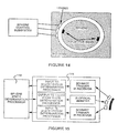
- FIG. 18 is a block diagram of a single-axis momentum wheel for terrestrial applications
- FIG. 19 is a drawing of a momentum wheel viewed from a top-down perspective, before the application of motor current;
- FIG. 20 is a drawing of a momentum wheel after the application of motor current
- FIG. 21 is a root-locus plot
- FIG. 22 is a time-response plot of a one-dimensional motor application according to the invention.
- FIG. 23 is a graph used to illustrate the control effort of a 1-D motor
- FIG. 24 is a drawing, as seen from an oblique perspective, of a hand-held force-feedback controller utilizing three momentum wheels to provide inertial stabilization in three space;
- FIG. 25 is a drawing of a block diagram of a spatially unrestricted force feedback controller utilizing three momentum wheels to provide inertial stabilization in three space.
- programmed amounts of rotary force are used for motion compensating and/or the stabilization of free-flying platforms, or to provide force/torque outputs from platforms to attached frames.
- Specific embodiments are disclosed with respect to spacecraft stabilization, as well as to the application of forces and/or torques to hand-held force generating devices, including joysticks, steering wheels, and implements of arbitrary shape for specific applications, such as sports simulations.
- reaction wheels use the inertia of one or more (typically up to three) rotating flywheels to generate torques. These wheels are typically accelerated using electric motors which can be controlled to increase or decrease rotary speed, thus changing rotational momentum. When the wheel on a particular axis is accelerated through increased motor torque, an equal and opposite reaction torque is generated and applied to the base upon which the wheel is mounted.
- Reaction wheels are the most precise type of attitude control mechanism. However, when called upon to provide non-cyclic torques, they must be periodically unloaded by other means (i.e. when the motors have accelerated to maximum RPM in any direction, no additional acceleration can be realized in that direction unless the motors are slowed, generating torques in the opposite direction). Moreover, to provide arbitrary torques, three wheel axes must be provided.
- reaction wheels as currently only applied only to spacecraft can be extended into several other related terrestrial applications, including gyro-stabilized bodies and tethered, force-generating/reflective input devices.
- gyro-stabilized bodies and tethered, force-generating/reflective input devices Preliminarily, the following description will demonstrate and how three axes of reaction wheel can be reduced into a single, reaction sphere, useful either in the space-based or terrestrial applications.
- a description of reaction wheels and spheres will first be presented, followed by a discussion of the extensions to such technology made possible by the invention.
- the singe plane model for a torque consists of a spinning wheel attached to a frame.
- a reference frame, B embedded in the frame and a fixed reference frame, A, in the world.
- Reference frame B is aligned with the axis of the spinning wheel.
- the system is shown in FIG. 1 .
- the center of mass of the frame is located at the origin of the B reference frame.
- the frame is assumed to be a cube with a mass of M and height of R.
- l is the offset from the center of the frame (in meters) and is a run-time parameter.
- the notation A v B denotes some vector v in reference frame B with respect to reference frame A.
- ⁇ is the density of the material of the wheel
- r is the radius of the disk and h is the height of the wheel; and have the units of kg/m 3 , meters and meters respectively.
- the orientation of the wheel with respect to the frame is given by the generalized coordinates q 3 .
- This generalized coordinate is about the b 1 axis.
- a ⁇ B u 1 b 1 (10)
- m is the mass of the momentum wheel
- r is the radius of the momentum wheel
- ⁇ is the torque applied to the operator (which is the same as the torque produce by the motor)
- ⁇ is the angular acceleration of the momentum wheel
- ⁇ is the angular velocity of the momentum wheel
- t is the period of time for which the torque is felt
- P is the power output of the motor.
- the motor rotor To feel a torque produced by a motor that is not attached to some fixed structure, the motor rotor must be accelerating. The rotor will continue to accelerate until the motor reaches its maximum angular velocity, a value that is determined by motor parameters (but the calculation of which is not important for this analysis). To increase the amount of time during which the torque can be felt, it is necessary to slow down the angular acceleration of the motor by increasing the moment of inertia of the rotor.
- a 3D platform consisting of three spinning wheels attached to three non-coplanar axes of a frame.
- a reference frame, B embedded in the frame and a fixed reference frame, A, in the world.
- Reference frame B is aligned with the axes of the three spinning wheels, thus defining a set of mutually perpendicular unit vectors.
- the system is shown in FIG. 2 .
- the reference frame B has six degrees of freedom with respect to reference frame A. These degrees of freedom are described by generalized coordinates q 1 , . . . , q 6 , where q 1 , . . . , q 8 represent the angular degrees of freedom about unit vectors a 1 ,a 2 ,a 3 respectively and q 4 , . . . , q 6 represent the linear degrees of freedom along unit vectors a 1 ,a 2 ,a 3 respectively.
- the orientation of reference frame B with respect to reference frame A is described using a Body 3: 1-2-3 representation. Table 1 shows the relationship between the unit vectors a 1 , a 2 , a 3 and b 1 , b 2 , b 3 .
- c i ,s i are defined as cos (q i ) and sin (q i ) respectively.
- the center of mass of the frame is located at the origin of the B reference frame and the frame is assumed to be cubical with a mass of M and height of R.
- ⁇ is the density of the material of the wheel
- r is the radius of the fisk
- h is the height of the wheel and have the units of kg/m 3 , meters and meters respectively.
- the orientation of the wheels with respect to the frame are given by the generalized coordinates q 7 , . . . , q 9 .
- These generalized coordinates are about the b 1 , b 2 , b 3 axes respectively.
- a ⁇ B (c 2 c 3 ⁇ dot over (q) ⁇ 1 +s 3 ⁇ dot over (q) ⁇ 2 )/b 2 +( ⁇ c 2 s 3 ⁇ dot over (q) ⁇ 1 +c 3 ⁇ dot over (q) ⁇ 2 )b 2 +(s 2 ⁇ dot over (q) ⁇ 1 + ⁇ dot over (q) ⁇ 3 )b 3 .
- a ⁇ B u 1 b 1 +u 2 b 2 +u 3 b 3 (40)
- a ⁇ d 1 (u 1 + ⁇ dot over (q) ⁇ 7 )b 1 +u 2 b 2 +u 3 b 3
- a ⁇ d 2 u 1 b 1 +(u 2 + ⁇ dot over (q) ⁇ 8 )b 2 +u 3 b 3
- a ⁇ d 3 u 1 b 1 +u 2 b 2 +(u 3 + ⁇ dot over (q) ⁇ 9 )b 3 (42)
- a ⁇ d 1 ( ⁇ dot over (u) ⁇ 1 + ⁇ dot over (u) ⁇ 7 )b 1 +( ⁇ dot over (u) ⁇ 2 +u 3 u 7 )b 2 +( ⁇ dot over (u) ⁇ 3 ⁇ u 2 u 7 )b 3
- a ⁇ d 2 ( ⁇ dot over (u) ⁇ 1 ⁇ u 3 u 8 )b 1 +( ⁇ dot over (u) ⁇ 2 + ⁇ dot over (u) ⁇ 8 )b 2 +( ⁇ dot over (u) ⁇ 3 +u 1 u 8 )b 3
- a ⁇ d 3 ( ⁇ dot over (u) ⁇ 1 +u 2 u 9 )b 1 +( ⁇ dot over (u) ⁇ 2 ⁇ u 1 u 9 )b 2 +( ⁇ dot over (u) ⁇ 3 + ⁇ dot over (u) ⁇ 9 )b 3 (46)
- a ⁇ d 2 Z 11 b 1 +Z 14 b 2 +Z 17 b 3
- a ⁇ d 3 Z 12 b 1 +Z 15 b 2 +Z 18 b 3 (48)
- a v B ⁇ dot over (q) ⁇ 4 a 1 + ⁇ dot over (q) ⁇ 5 a 2 + ⁇ dot over (q) ⁇ 6 a 3
- a ⁇ B q 4 a 1 + q 5 a 2 + q 6 a 3 (50)
- Equation (50) allows rewriting Equation (50) as A v B u 4 a 1 +u 5 a 2 +u 6 a 3 A a B ⁇ dot over (u) ⁇ 4 a 1 + ⁇ dot over (u) ⁇ 5 a 2 + ⁇ dot over (u) ⁇ 6 a 3 (52)
- a a d 1 ⁇ dot over (u) ⁇ 4 a 1 + ⁇ dot over (u) ⁇ 5 a 2 + ⁇ dot over (u) ⁇ 6 a 3 ⁇ l(u 2 2 +u 3 2 )b 2 +l(u 1 u 2 + ⁇ dot over (u) ⁇ 3 )b 2 +l(u 1 u 3 ⁇ dot over (u) ⁇ 2 )b 3
- a a d 2 ⁇ dot over (u) ⁇ 4 a 1 + ⁇ dot over (u) ⁇ 5 a 2 + ⁇ dot over (u) ⁇ 6 a 3 +l(u 2 u 2 ⁇ dot over (u) ⁇ 2 )b 2 +l(u 2 u 3 ⁇ dot over (u) ⁇ 1 )b 2 ⁇ l(u 1 2 +u 2 )b 3 (54)
- G d 1 ⁇ mga 3
- G d 2 ⁇ mga 3
- G d 3 ⁇ mga 3 (58)
- G d 1 ⁇ mg(Z 3 b 1 +Z 6 b 2 +Z 9 b 3 )
- G d 2 ⁇ mg(Z 3 b 1 +Z 6 b 2 +Z 9 b 3 )
- G d 3 ⁇ mg(Z 3 b 1 +Z 6 b 2 +Z 9 b 3 ) (59)
- T D ⁇ x a 1 + ⁇ y a 2 + ⁇ z a 3 (60)
- T d 1 ⁇ d 1 b 1
- T d 2 ⁇ d 2 b 2
- T d 3 ⁇ d 3 b 3
- Z 19 l ( u 2 2 + u 3 2 )
- Z 22 l ( u 1 ⁇ u 2 + u . 3 )
- Z 25 l ( u 1 ⁇ u 3 - u . 2 )
- Z 20 l ( u 1 ⁇ u 2 - u . 3 )
- Z 23 l ( u 1 2 + u 3 2 )
- Z 26 l ( u 2 ⁇ u 3 + u . 1 )
- Z 21 l ( u 1 ⁇ u 3 + u . 2 )
- Z 24 l ( u 2 ⁇ u 3 - u . 1 )
- Z 27 l ( u 1 2 ⁇ u 3 + u 2 2 ) , ( 63 )
- Equation (39) rewriting Equation (39) to solve for the q i in terms of the u i .
- Equation (64) To write the dynamical equations of motion in the same manner, Equation (64) must be solved for the ⁇ dot over (u) ⁇ i . Since several of the Z i include ⁇ dot over (u) ⁇ t , these terms will need to be expanded.
- K 1 I 2 (u 2 u 9 ⁇ u 3 u 8 ) ⁇ mlg(Z 6 ⁇ Z 9 ) ⁇ x Z 1 ⁇ y Z 2 ⁇ z Z 3
- K 2 I 2 (u 3 u 7 ⁇ u 1 u 9 ) ⁇ mlg(Z 9 ⁇ Z 3 ) ⁇ x Z 4 ⁇ y Z 5 ⁇ z Z 6
- K 3 I 2 (u 1 u 8 ⁇ u 2 u 7 ) ⁇ mlg(Z 3 ⁇ Z 6 ) ⁇ x Z 7 ⁇ y Z 8 ⁇ z Z 9 (68)
- K 4 m((l(Z 28 +Z 29 ) ⁇ Z 19 )Z 1 +(l(Z 28 +Z 30 ) ⁇ Z 23 )Z 4 +(l(Z 29 +Z 30 ) ⁇ Z 27 )Z 7 ) ⁇ f x
- Equation (69) yields [ - ( I 4 + 2 ⁇ ⁇ m ⁇ ⁇ l 2 ) 0 0 - I 2 0 0 0 - ( I 4 + 2 ⁇ ⁇ m ⁇ ⁇ l 2 ) 0 0 - I 2 0 0 0 - ( I 4 + 2 ⁇ ⁇ m ⁇ ⁇ l 2 ) 0 0 - I 2 0 0 0 - ( I 4 + 2 ⁇ ⁇ m ⁇ ⁇ l 2 ) 0 0 - I 2 - I 2 0 0 - I 2 0 0 0 - I 2 0 0 - I 2 0 0 - I 2 0 0 - I 2 0 0 - I 2 ] ] ⁇ [ u .
- equations of motion for the sphere can be derived from those for the three wheel device by noting these two salient differences between the systems: the inertia of the sphere is equal in all directions and is unchanged with orientations; and the center of mass of the sphere is located at the origin of reference frame B.
- the equations of motion for the sphere are given by:
- controlling a system that employs this device for stabilization is easier than controlling a system that employs three reactions wheels for stabilization.
- Control theory is defined as a division of engineering mathematics that attempts, through modeling, to analyze and to command a system in a desired manner.
- closed-loop systems In a closed-loop system, the forcing signals of the system (calling inputs) are determined (at least partially) by the responses (or output) of the system. In this manner, the inputs and outputs are interrelated.
- FIG. 4 a generic closed-loop control system is shown. In order to explain the contents of this diagram, the following example is used:
- Control theory can be classified in two categories: classical and modern.
- Classical control theory is generally a trial-and-error system in which various type of analyses are used iteratively to force a electromechanical system to behave in an acceptable manner.
- the performance of a system is measured by such elements as setting time, overshoot and bandwidth.
- MIMO multi-input/multi-output
- Modern control has seen wide-spread usage within the last fifteen years or so. Advancements in technology, such as faster computers, cheaper and more reliable sensors and the integration of control considerations in product design, have made it possible to extend the practical applications of automatic control to systems that were impossible to deal with in the past using classical approaches.
- Modern control theories are capable of dealing with issues such as performance and robustness.
- the spatially-unrestricted force-feedback system makes use of two modern control design methods: disturbance rejection and optimal control.
- a disturbance may be defined as an unwanted input.
- the disturbance, w(t) is shown as a second input to the plant. The effect of the disturbance is added to the output of the plant.
- Disturbance rejection design can be used to create a compensator which is able to ignore the disturbance and cause the desired plant output.
- the basic method of disturbance rejection design is presented during a MIMO model. For this model, notation must be established to designate the various elements of the control device; let:
- [A, B, C, D] be a state-space representation of the plant (with state x), assuming (A,B) is completely controllable, x(t) ⁇ n be the plant state, u(t) ⁇ n i be the plant inside (where n i is the number of inputs and n o is the number of outputs), w(t) ⁇ d be the disturbance input x(t) ⁇ n o be the desired or reference input y(t) ⁇ n o be the sensor output e(t) ⁇ n o be the tracking error
- Optimal control theory can be used to design compensators which are able to take into account the cost of performing a particular action.
- a classical example of optimal control is the use of fuel to maneuver a satellite in orbit above the earth. Two extreme scenarios are possible: movement taking minimum time or movement taking minimum fuel. In the following section, discussion will focus on the fundamental principles of optimal-control design.
- J a ⁇ ( u ) ⁇ t 0 t f ⁇ ⁇ g [ x ( t ) , u ( t ) , t ] + [ ⁇ h ⁇ x ⁇ ( x ( t ) , t ) ] T ⁇ x ( t ) + ⁇ h ⁇ t ⁇ ( x ( t ) , t ) + p T ⁇ ( t ) [ a ( x ( t ) , u ( t ) ) , t ) - x . ( t ) ⁇ ] ⁇ ⁇ d ⁇ ⁇ t ( 89 )
- the principles of calculus of variations are applied to the design of a linear regulator.
- the linear regulator is used in the control of the motors used to spin the inertial masses to change the attitude of the satellite system.
- the regulator design is particularly useful in controlling unstable systems through optimal pole placement.
- t f is fixed
- H and Q are real, positive-semi-definite matrices
- R is a real, positive-definite matrix.
- the purpose of the regulator is to maintain the state of the system as close to a desired set of parameters as possible without excessive control effort.
- the closed-loop system is guaranteed to be stable and the controller may be used for pole placement design of the system, as shown in FIG. 6 .
- the design of the controller system for the 1D model is now presented.
- the first segment of the design is a optimal pole-placement. This is needed because a the 1D model of the spatially unrestricted force feedback device (which is a simplified version of the actual 3D version), which can be considered a second-order system, is inherently unstable. Definitions of “stable” vary; here, “stable” is considered any plant which has only poles and zeros to the left of the imagery axis in the complex plane (i.e., left-hand poles and zeros). Using previously established results, the poles of the system are placed optimally based on the inertia of a second-order linear model. Lastly, disturbance rejection is augmented to the control system for robustness.
- ⁇ (t) is the angular acceleration
- I 6 is the inertial mass
- ⁇ (t) is the torque
- the first step is to choose the cost function to minimize, set initial conditions, and select the necessary conditions and boundary conditions which apply to this problem.
- the two terms of the F vector are the position feedback and velocity feedback required for optimal tracking, as in FIG. 8 .
- the final step is to include an integrator which provides the SISO case with robustness.
- the final controller design is shown in FIG. 9 .
- Each of the three sphere housing axis is outfitted with a band of optical infra-red emitters to detect the relative position of the sphere.
- Each emitter will be placed between two (or more) infra-red detectors as shown in FIG. 11 . This technique will enable fine position sensing and simultaneously minimize power requirements since a single emitter will service two (or more) detectors.
- the sphere is equipped with a single great circle band of reflective material as illustrated in FIG. 12 .
- each sensor band on the sphere housing covers one half of the great circle band on each sphere housing axis. Consequently the reflective band is always within range of at least three optical emitter/detector pairs regardless of sphere orientation.
- the IR emitter/detector sensors are located directly on the cavity face to simplify construction of the sphere housing. Each emitter and detector is directly interfaced to the housing cavity by a fiber optic cable that ends at a lens mounted on the cavity face as shown in FIG. 14 . Using a lens permits the use of lower power infra-red emitters.
- the infra-red emitters are driven by an output bit from the Sphere Control Computer.
- the control computer reads the associated IR receiver, via the same decode multiplexor logic in the Sphere Control Subsystem.
- celestial mechanics deals with the position and velocity of the center of mass of the spacecraft as it travels through space, whereas the latter deals with the motion of the spacecraft about its center of mass, see FIG. 16 .
- Attitude mechanics is divided into three components: determination, prediction and control.
- Attitude determination is the process of computing the current orientation of the spacecraft with respect to some specified inertial frame.
- Attitude prediction is the process of computing the future attitude of the spacecraft based on its current state and motion.
- Attitude control is the process of applying torques to the spacecraft to reorient it into some desired future state.
- the devices mentioned in this patent deal primarily with the control aspect of attitude mechanics.
- three axis stabilized spacecraft employ sensing devices that identify the spacecraft's attitude by determining two mutually perpendicular orientation vectors.
- Some typical examples include two-axis sun sensors and magnetic field sensors.
- reaction jets operate by expelling gas through an orifice to impart a moment on the spacecraft. These devices can produce large (but imprecise) torques, but since they expend fuel, there on-station operating time is limited.
- Electromagnets operate by creating magnet fields that interact with the magnetic field of a nearby body to produce a torque on the satellite. Although these systems do no expend fuel, they only function near bodies with large magnetic fields.
- Reaction wheels operate by way of Newton's third law by accelerating a wheel to absorb torque that is applied to the satellite. If the applied disturbances are cyclic, these systems can operate indefinitely since there is not net gain/loss of energy. For real-world systems, reaction wheels typically operate in conjunction with gas jets, which are used to bleed off excess momentum as the wheels approach their operating condition boundaries. Reaction wheels provide a very fine degree of attitude control.
- a sensor platform is to collect data from a lake over a period of time. If this platform is required to maintain a particular attitude, a gyroscopic system can be used for stabilization. Similarly, a sensor platform mounted on a research balloon may be required to maintain two-axis attitude control for the duration of the mission. Again, a gyroscopic system can be used to stabilize the two rotational degrees of freedom of this system.
- Equation (119) was intended to validate Equation (119).
- a second experiment was intended to demonstrate a control system for a three DOF system.
- test stand was developed, as shown in FIG. 18 .
- This test setup consists of the following components:
- the position, velocity, and/or acceleration provided on a user-interactable member is sensed and transmitted as a command to a computer model or simulation which implements a virtual reality force field.
- the force field value for the given position, velocity, and/or acceleration is sent back to the member, which generates a force command, thereby providing the user with direct kinesthetic feedback from the virtual environment traversed.
- the technology is also well suited to the control of a remote or physical device. Further, the present invention is suited for application to any number of axes.
- These electrical signals are fed to a virtual reality force field generator which calculates force field values for a selected force field.
- These force field values are fed to the force signal generator which generates a force signal for each of the plurality of degrees of freedom of the user as a function of the generated force field.
- These motion commands are fed back to actuators of the user interface which provide force to the user interface and, thus, to the user in contact with the interface device.
- Equation (119) Using the motor electrical parameters and the electrical characteristics of the IMC chassis, the maximum torque that can be applied by the motor is known to be 0.18 Nm. Inserting these values into Equation (119) yields a time of 0.09 seconds.
- control parameters determined using the optimal control techniques and the root-locus method were applied to the system shown in FIG. 18 (without the spring). Since the control equations require the moment of inertia of the platform, CAD tools were used to calculate the moment of inertia of the motor, the adapter plate and the bolt. One item that was not modeled in the simulation, or the calculations for determining control parameters, was the friction in the system.
- FIG. 23 shows actual data from an experiment to control the physical device. Despite the friction problem, the results from this test are as expected. The system does oscillate about the control point, though it is quite noisy.
- the motors were spun up to a speed of 5000 RPM. Individuals were asked to handle the device and to make subjective evaluations of the torques felt as the device was moved about. In all cases, the subjects reported feeling appreciable forces that were deemed to be sufficient for carrying out meaningful tasks.
- a picture of the device is shown in FIG. 24 .
- the torques felt were generated because the control system had been commanded to maintain the momentum wheels at a constant angular velocity. By moving the device about, the angular momentum vectors were changed, thus causing a torque.
- the control system compensated for these motions by adjusting the output to the motors. Since the motors were already spinning at high speed, the period of time for which a torque could be applied was far more limited than for the case where the motor is initially at rest.
- the final task is to control the motors in an appropriate manner so as to provide haptic feedback to the user.
- This task requires a sophisticated control algorithm for two reasons: first, the platform will be grossly displaced from its nominal operating orientation, and second, for any motion of the platform (for simplicity consider just rotations about the world coordinate axes with which the device is initially oriented), some subset of the motors will produce torques (due to changes in the orientation of the angular momentum vectors) that are undesired. To counteract these undesired torques, some subset of the motors will need to be accelerated to produce counter torques.
- the control system must model the full, non-linear dynamics of the system, have a high speed attitude sensor and possibly a control to smoothly generate the prescribed forces.
- a block diagram of the system is shown in FIG. 25 .
- one family of applications for the devices described above utilizes inputs received from a virtual environment.
- the virtual environment models some set of objects, and hand controller or other force-reflection device produces forces that are representative of some activity within the virtual environment. Since it is not required that the forces produced correlate to any specific activity, the only restriction placed on the commands sent to the gyro-stabilized device is that the output forces be within the range of forces that the device can produce.
- An alternative family of applications for these devices produces forces in accordance with inputs received from a (possibly remote) physical device.
- the forces produced are typically a scaled representation of the actual forces produced at some point on the actual physical device. To provide the widest range of haptic input, the scaling is typically designed such that the maximum force that can be applied to the physical device is mapped into the maximum force that the haptic device can produce.
- a two step controller is preferably utilized.
- the first step stabilizes the controller by doing a pole placement.
- the location of the poles can be determined using any applicable method although optimal control is preferred.
- the second step creates a robust controller by canceling out disturbance inputs. Robust control theory is applied for this task.
- the desired input is typically a zero input, i.e., that the system should not change state.
- sensor are employed to determine when the system changes state due to disturbances and the controller acts to return the system to the zero state.
- the human operator who controls the haptic device is, from the perspective of the momentum device, equivalent to group.
- the strategy is to slowly and continually remove angular momentum so as to have as minimal affect on the user as possible.
- the momentum sphere has a maximum speed at which it can operate due to the materials and construction techniques employed. When the sphere approaches this maximum velocity, momentum must be unloaded from the sphere for it to continue to function. To do this requires the application of an external torque that will cause the angular momentum vector to be diminished. This can be accomplished in three ways: reaction jets, magnetic field torques and/or spacecraft reorientation.
- the first two methods work by applying a torque to the spacecraft that diminished the angular momentum of the sphere.
- the third method works if the following two conditions are met: the disturbances to the spacecraft are primarily applied in the same direction and the spacecraft can continue to operate at different attitudes. If these conditions are met, the spacecraft can be reoriented such that the disturbance torque act to cancel the sphere's angular momentum. It may also be feasible to rigidly couple the platform to ground for a brief period of time. While coupled to ground, any amount of angular momentum can be removed from the stabilized platform.
Abstract
Description
a1=b1. (1)
Bpd=lb1 (2)
m=πρr2h (3)
Id/d+=I2b1b1 (4)
If/f+=I6b1b1 (6)
AωB={dot over (q)}1b1. (8)
u1={dot over (q)}1. (9)
AωB=u1b1 (10)
Bωd={dot over (q)}7b1. (11)
Aωd=(u1+{dot over (q)}7)b1. (12)
u7={dot over (q)}7 (13)
Aωd=(u1+u7)b1. (14)
AαB={dot over (u)}1b1. (15)
Aαd=({dot over (u)}1+{dot over (u)}7)b1. (16)
ApB=q4a1. (17)
AvB={dot over (q)}4a1 AaB={dot over (q)}4a1 (18)
since the unit vectors ai are fixed in reference frame A. Defining a generalized velocity
u4={dot over (q)}4 (19)
allows rewriting Equation (18) as
AvB=u4a1 AaB={dot over (u)}4a1 (10)
F=fxa1, (21)
Td=τxa1, and (22)
Td=τab1 (23)
τx−((I2+I6){dot over (u)}1+I2{dot over (u)}7)=0
fm−(M+m){dot over (u)}4=0
τd−(I2{dot over (u)}2+I2{dot over (u)}7)=0 (24)
τd+I2{dot over (u)}1=0. (26)
τd+I2{dot over (u)}1=τx (27)
I=mr2 τ=Iα
ω=αt P=τω (28)
| TABLE 1 |
| Direction cosines |
| b1 | b2 | b3 | ||
| a1 | c2c3 | −c2s3 | s2 | ||
| a2 | s1s2c3 + s3c1 | −s1s2s3 + c3c1 | −s1c2 | ||
| a3 | −c1s2c3 + s3s1 | c1s2s3 + c3s1 | c1c2 | ||
a1=Z1b1+Z4b2+Z7b3
a2=Z2b1+Z5b2+Z8b3
a3=Z3b1+Z6b2+Z9b3 (31)
Iƒ/ƒ+=I6b1b1+I6b2b2+I6b3b3 (32)
where
Bpd
m=πρr2h (35)
Id
Id
Id
AωB=(c2c3{dot over (q)}1+s3{dot over (q)}2)/b2+(−c2s3{dot over (q)}1+c3{dot over (q)}2)b2+(s2{dot over (q)}1+{dot over (q)}3)b3. (38)
u1=c2c3{dot over (q)}1+s3{dot over (q)}2 u2=−c2s3{dot over (q)}1+c3{dot over (q)}2 u3=s2{dot over (q)}1+{dot over (q)}3. (39)
AωB=u1b1+u2b2+u3b3 (40)
Bωd
Aωd
Aωd
Aωd
u7={dot over (q)}7 u8={dot over (q)}8 u9={dot over (q)}9 (43)
Aωd
Aωd
Aωd
AαB={dot over (u)}1b1+{dot over (u)}2b2+{dot over (u)}3b3. (45)
Aαd
Aαd
Aαd
Aαd
Aαd
Aαd
ApB=q4a1+q5a2+q6a3. (49)
AvB={dot over (q)}4a1+{dot over (q)}5a2+{dot over (q)}6a3 AαB=
u4={dot over (q)}4 u5={dot over (q)}5 n6={dot over (q)}6 (51)
AvBu4a1+u5a2+u6a3 AaB{dot over (u)}4a1+{dot over (u)}5a2+{dot over (u)}6a3 (52)
Avd
Avd
Avd
Aad
Aad
F=fxa1+fya2+fza3 (55)
Gƒ=−Mga3 (56)
Gƒ=−Mg(Z3b1+Z6b2+Z9b3); (57)
Gd
Gd
Gd
Gd
TD=τxa1+τya2+τza3 (60)
Td
T=τxa1+τya2+τza3−τd
fy−m(3{dot over (u)}5+(−Z19+Z20+Z21)Z2+(Z22−Z23+Z24)Z5+(Z25+Z26−Z27)Z8)−M{dot over (u)}5=0
fz−m(3g+3{dot over (u)}6+(−Z19+Z20Z21)Z3+(Z22−Z23+Z24)Z6+(Z25+Z26−Z27)Z9)−M{dot over (u)}6=0
τd
τd
τd
{dot over (y)}=f(y) (65)
Z28=a1u2 Z29=u1u3 Z30=u2u3 (67)
K1=I2(u2u9−u3u8)−mlg(Z6−Z9)−τxZ1−τyZ2−τzZ3
K2=I2(u3u7−u1u9)−mlg(Z9−Z3)−τxZ4−τyZ5−τzZ6
K3=I2(u1u8−u2u7)−mlg(Z3−Z6)−τxZ7−τyZ8−τzZ9 (68)
K4=m((l(Z28+Z29)−Z19)Z1+(l(Z28+Z30)−Z23)Z4+(l(Z29+Z30)−Z27)Z7)−fx
K5=m((l(Z28+Z29)−Z19)Z2+(l(Z28+Z30)−Z25)Z5+(l(Z29+Z30)−Z27)Z8)−fy
K6=m(3g+(l(Z28+Z29)−Z19)Z3+(l(Z28+Z30)−Z23)Z6+(l(Z29+Z30)−Z27)Z9)−fz
K7=−τd
where I4=2I1+I2+I6.
where I5=(I4+2ml2)−I2.
τxZ4+τyZ5+τzZ6−[(I1+I6){dot over (u)}2+I1{dot over (u)}8+I1(u3u7−u1u9)]=0
τxZ7+τyZ8+τzZ9−[(I1+I6){dot over (u)}3+I1{dot over (u)}9+I1(u1u8−u2u7)]=0
fx−(m+M){dot over (u)}4=0
fy−(m+M){dot over (u)}5=0
fz−(m+M)3{dot over (u)}6−mg=0
τd
τd
τd
-
- The objective is to control the temperature of a room. In this case, the sensor is the thermostat. The system input is set by selecting a temperature. Through either some mechanical or electrical means, the difference between the desired and actual temperature is calculated, resulting in an error. If the actual temperature is below the desired, the compensator sends out a control signal to the furnace (or plant). If the control signal says heat on (actually, the electromechanical equivalent), the furnace outputs heat. This process continues until the compensator determines it is not necessary to heat the room, and the control signal is changed to a heat off signal.
x(t)ε
u(t)ε
w(t)ε
x(t)ε
y(t)ε
e(t)ε
{dot over (x)}=Ax+Bu+Ew (73)
y=Cx+Du+Fw (74)
e=r−y (75)
{dot over (x)}r=Arxr (76)
r=Crxr (77)
{dot over (x)}w=Awxw (78)
w=Cwxw (79)
-
- Closed-loop system must be exponentially stable,
- Achieve asymptotic tracking and disturbance rejection for all initial states
- Robustness
{dot over (x)}o=Acx+Bce (80)
where
Ac=diag[Γ1,Γ2, . . . , Γn
Bc=diag[γ1,γ2, . . . , γn]ε
with
Φ(Aw;Ar)=sQ+α1sQ−1+. . .+αq−1+s+α1 (85)
-
- The composite system is completely controllable
- Asymptotic tracking and disturbance rejection holds
- Asymptotic tracking and disturbance rejection are robust
for all tε[to, tf], and
where
N(x(t),u(t),p(t),t)≡g(x(t),u(t),p(t),t)+p2[a(x(t),u(t),p(t),t] (95)
{dot over (x)}(t)=A(t)x(t)+B(t)u(t) (96)
{dot over (x)}*(t)=A(t)x*(f)+B(t)u*(t) (98)
{dot over (p)}*(t)=−Q(t)x*(t)−Ar(t)p*(t) (99)
O=R(t)u*(t)+BT(t)p*(t) (100)
u*(t)=−R−1(t)BT(t)p*(t) (102)
p*(t)=K(t)x*(t). (105)
u*(t)=−R−1(t)BT(t)K(t)x*(t)=F(t)(x*(t)); (106)
{dot over (K)}(t)=−K(t)A(t)−AT(t)K(t)−Q(t)+K(t)B(t)R−1(t)BT(t)K(t) (107)
{dot over (x)}(t)=Ax(t)+Bu(t) (108)
u*(t)=−R−1BTKx*(t)=Fx*(t). (111)
and R=1.
-
- A turntable with an attached motor. The position of the turntable is instrumented with an incremental encoder attached directly to the turntable (not used in this experiment). The position of the motor shaft was not instrumented, however, its angular velocity is instrumented. The motor employed is a Hathaway model 1500, attached to the turntable by means of an adapter block.
- A momentum wheel attached to the motor shaft. This momentum wheel is manufactured from a piece of stock, 2 inch diameter, cast iron shaft.
- The motor is attached to a CyberImpact® Intelligent Motor Controller (IMC) system, a standard Cybernet product and is used with all of our force feedback devices, which provides an interface to a PC board controller that allows for a wide range of motion commands to be programmed.
- The IMC is attached to a PC. In this example, a simple, previously developed interface to start and stop the motor was employed. This interface presents the user with an input screen for directly controlling the motor current. By setting the current to its maximum allowable value, the maximum obtainable torque is observed. By setting the current to zero, the motor comes to a stop.
- A torque measuring system consisting of a spring and a camera. Applied torque was measured by the displacement of a known spring and the time for this to happen by counting video frames.
-
- The instrumented readings from the turntable and the motor shaft were used by the controller.
- The spring was removed from the experimental setup.
- A control program was written that interfaces directly with the IMC system.
Claims (29)
Priority Applications (2)
| Application Number | Priority Date | Filing Date | Title |
|---|---|---|---|
| US09/888,291 USRE39906E1 (en) | 1995-10-26 | 2001-06-21 | Gyro-stabilized platforms for force-feedback applications |
| US11/782,998 USRE44396E1 (en) | 1995-10-26 | 2007-07-25 | Gyro-stabilized platforms for force-feedback applications |
Applications Claiming Priority (4)
| Application Number | Priority Date | Filing Date | Title |
|---|---|---|---|
| US586195P | 1995-10-26 | 1995-10-26 | |
| US08/736,016 US5754023A (en) | 1995-10-26 | 1996-10-22 | Gyro-stabilized platforms for force-feedback applications |
| US09/452,682 USRE37374E1 (en) | 1995-10-26 | 1999-11-30 | Gyro-stabilized platforms for force-feedback applications |
| US09/888,291 USRE39906E1 (en) | 1995-10-26 | 2001-06-21 | Gyro-stabilized platforms for force-feedback applications |
Related Parent Applications (2)
| Application Number | Title | Priority Date | Filing Date |
|---|---|---|---|
| US08/736,016 Reissue US5754023A (en) | 1995-10-26 | 1996-10-22 | Gyro-stabilized platforms for force-feedback applications |
| US09/452,682 Continuation USRE37374E1 (en) | 1995-10-26 | 1999-11-30 | Gyro-stabilized platforms for force-feedback applications |
Related Child Applications (1)
| Application Number | Title | Priority Date | Filing Date |
|---|---|---|---|
| US08/736,016 Continuation US5754023A (en) | 1995-10-26 | 1996-10-22 | Gyro-stabilized platforms for force-feedback applications |
Publications (1)
| Publication Number | Publication Date |
|---|---|
| USRE39906E1 true USRE39906E1 (en) | 2007-11-06 |
Family
ID=27357973
Family Applications (2)
| Application Number | Title | Priority Date | Filing Date |
|---|---|---|---|
| US09/888,291 Expired - Lifetime USRE39906E1 (en) | 1995-10-26 | 2001-06-21 | Gyro-stabilized platforms for force-feedback applications |
| US11/782,998 Expired - Lifetime USRE44396E1 (en) | 1995-10-26 | 2007-07-25 | Gyro-stabilized platforms for force-feedback applications |
Family Applications After (1)
| Application Number | Title | Priority Date | Filing Date |
|---|---|---|---|
| US11/782,998 Expired - Lifetime USRE44396E1 (en) | 1995-10-26 | 2007-07-25 | Gyro-stabilized platforms for force-feedback applications |
Country Status (1)
| Country | Link |
|---|---|
| US (2) | USRE39906E1 (en) |
Cited By (18)
| Publication number | Priority date | Publication date | Assignee | Title |
|---|---|---|---|---|
| US20060020174A1 (en) * | 2004-07-21 | 2006-01-26 | Yoshihiro Matsumura | Physical activity measuring system |
| US20070135264A1 (en) * | 2005-12-09 | 2007-06-14 | Outland Research, Llc | Portable exercise scripting and monitoring device |
| US20070275826A1 (en) * | 2006-05-29 | 2007-11-29 | Polar Electro Oy | Method and wrist device |
| US20080032870A1 (en) * | 2006-08-02 | 2008-02-07 | Shen Yi Wu | Method and apparatus of counting steps for treadmill |
| US20080108481A1 (en) * | 2003-12-05 | 2008-05-08 | Ilkka Limma | Method, System, Measurement Device and Receiving Device for Providing Feedback |
| US20080132313A1 (en) * | 2005-09-08 | 2008-06-05 | Rasmussen James M | Gaming machine having display with sensory feedback |
| US20080146416A1 (en) * | 2006-12-13 | 2008-06-19 | Motorola, Inc. | Generation of user activity feedback |
| US20110046793A1 (en) * | 2009-08-18 | 2011-02-24 | Rong Zhi Xin Science and Technology Development (Beijing) Co., Ltd. | Stabilized platform system |
| US8210942B2 (en) | 2006-03-31 | 2012-07-03 | Wms Gaming Inc. | Portable wagering game with vibrational cues and feedback mechanism |
| US20140088914A1 (en) * | 2011-05-31 | 2014-03-27 | Resonic Gmbh | System and method for determining inertia properties of a rigid body |
| US9058714B2 (en) | 2011-05-23 | 2015-06-16 | Wms Gaming Inc. | Wagering game systems, wagering gaming machines, and wagering gaming chairs having haptic and thermal feedback |
| US9142083B2 (en) | 2011-06-13 | 2015-09-22 | Bally Gaming, Inc. | Convertible gaming chairs and wagering game systems and machines with a convertible gaming chair |
| US9509269B1 (en) | 2005-01-15 | 2016-11-29 | Google Inc. | Ambient sound responsive media player |
| US20180003146A1 (en) * | 2015-01-09 | 2018-01-04 | Wello Oy | Method and system for adjusting the torque of a mass and spinning wheel rotator in a wave power plant |
| US20190163209A1 (en) * | 2017-11-29 | 2019-05-30 | Ubtech Robotics Corp | Method, terminal device, and computer readable storage medium for controlling rotation of servo |
| US10375290B2 (en) * | 2017-11-20 | 2019-08-06 | Ross Video Limited | Video equipment control |
| US10613629B2 (en) | 2015-03-27 | 2020-04-07 | Chad Laurendeau | System and method for force feedback interface devices |
| US11490018B2 (en) * | 2017-07-06 | 2022-11-01 | Japan Aerospace Exploration Agency | Mobile image pickup device |
Families Citing this family (14)
| Publication number | Priority date | Publication date | Assignee | Title |
|---|---|---|---|---|
| US8847989B1 (en) * | 2013-01-19 | 2014-09-30 | Bertec Corporation | Force and/or motion measurement system and a method for training a subject using the same |
| US11311209B1 (en) | 2013-01-19 | 2022-04-26 | Bertec Corporation | Force measurement system and a motion base used therein |
| US10856796B1 (en) | 2013-01-19 | 2020-12-08 | Bertec Corporation | Force measurement system |
| US10646153B1 (en) | 2013-01-19 | 2020-05-12 | Bertec Corporation | Force measurement system |
| US11052288B1 (en) | 2013-01-19 | 2021-07-06 | Bertec Corporation | Force measurement system |
| US9770203B1 (en) | 2013-01-19 | 2017-09-26 | Bertec Corporation | Force measurement system and a method of testing a subject |
| US9081436B1 (en) | 2013-01-19 | 2015-07-14 | Bertec Corporation | Force and/or motion measurement system and a method of testing a subject using the same |
| US11540744B1 (en) | 2013-01-19 | 2023-01-03 | Bertec Corporation | Force measurement system |
| US10010286B1 (en) | 2013-01-19 | 2018-07-03 | Bertec Corporation | Force measurement system |
| US10231662B1 (en) | 2013-01-19 | 2019-03-19 | Bertec Corporation | Force measurement system |
| US9526443B1 (en) | 2013-01-19 | 2016-12-27 | Bertec Corporation | Force and/or motion measurement system and a method of testing a subject |
| US8704855B1 (en) | 2013-01-19 | 2014-04-22 | Bertec Corporation | Force measurement system having a displaceable force measurement assembly |
| US10413230B1 (en) | 2013-01-19 | 2019-09-17 | Bertec Corporation | Force measurement system |
| US11857331B1 (en) | 2013-01-19 | 2024-01-02 | Bertec Corporation | Force measurement system |
Citations (62)
| Publication number | Priority date | Publication date | Assignee | Title |
|---|---|---|---|---|
| US3157853A (en) | 1957-12-06 | 1964-11-17 | Hirsch Joseph | Tactile communication system |
| US3220121A (en) | 1962-07-08 | 1965-11-30 | Communications Patents Ltd | Ground-based flight training or simulating apparatus |
| US3497668A (en) | 1966-08-25 | 1970-02-24 | Joseph Hirsch | Tactile control system |
| US3517446A (en) | 1967-04-19 | 1970-06-30 | Singer General Precision | Vehicle trainer controls and control loading |
| US3623064A (en) | 1968-10-11 | 1971-11-23 | Bell & Howell Co | Paging receiver having cycling eccentric mass |
| US3902687A (en) | 1973-06-25 | 1975-09-02 | Robert E Hightower | Aircraft indicator system |
| US3903614A (en) | 1970-03-27 | 1975-09-09 | Singer Co | Apparatus for simulating aircraft control loading |
| US3911416A (en) | 1974-08-05 | 1975-10-07 | Motorola Inc | Silent call pager |
| US4160508A (en) | 1977-08-19 | 1979-07-10 | Nasa | Controller arm for a remotely related slave arm |
| US4236325A (en) | 1978-12-26 | 1980-12-02 | The Singer Company | Simulator control loading inertia compensator |
| US4262549A (en) | 1978-05-10 | 1981-04-21 | Schwellenbach Donald D | Variable mechanical vibrator |
| US4333070A (en) | 1981-02-06 | 1982-06-01 | Barnes Robert W | Motor vehicle fuel-waste indicator |
| US4443952A (en) * | 1981-11-09 | 1984-04-24 | The Bendix Corporation | Gyroscopic apparatus |
| US4464117A (en) | 1980-08-27 | 1984-08-07 | Dr. Ing. Reiner Foerst Gmbh | Driving simulator apparatus |
| US4484191A (en) | 1982-06-14 | 1984-11-20 | Vavra George S | Tactile signaling systems for aircraft |
| US4513235A (en) | 1982-01-22 | 1985-04-23 | British Aerospace Public Limited Company | Control apparatus |
| US4581491A (en) | 1984-05-04 | 1986-04-08 | Research Corporation | Wearable tactile sensory aid providing information on voice pitch and intonation patterns |
| US4599070A (en) | 1981-07-29 | 1986-07-08 | Control Interface Company Limited | Aircraft simulator and simulated control system therefor |
| US4708656A (en) | 1985-11-11 | 1987-11-24 | Fokker B.V. | Simulator of mechanical properties of a steering system |
| US4713007A (en) | 1985-10-11 | 1987-12-15 | Alban Eugene P | Aircraft controls simulator |
| US4794392A (en) | 1987-02-20 | 1988-12-27 | Motorola, Inc. | Vibrator alert device for a communication receiver |
| JPS643664A (en) | 1987-06-26 | 1989-01-09 | Hitachi Ltd | Laser beam marking device |
| US4891764A (en) | 1985-12-06 | 1990-01-02 | Tensor Development Inc. | Program controlled force measurement and control system |
| JPH02109714A (en) | 1988-10-20 | 1990-04-23 | Suzuki Motor Co Ltd | Stabilizer fitting mechanism |
| US4930770A (en) | 1988-12-01 | 1990-06-05 | Baker Norman A | Eccentrically loaded computerized positive/negative exercise machine |
| US4934694A (en) | 1985-12-06 | 1990-06-19 | Mcintosh James L | Computer controlled exercise system |
| US5019761A (en) | 1989-02-21 | 1991-05-28 | Kraft Brett W | Force feedback control for backhoe |
| US5022384A (en) | 1990-05-14 | 1991-06-11 | Capitol Systems | Vibrating/massage chair |
| US5022407A (en) | 1990-01-24 | 1991-06-11 | Topical Testing, Inc. | Apparatus for automated tactile testing |
| US5035242A (en) | 1990-04-16 | 1991-07-30 | David Franklin | Method and apparatus for sound responsive tactile stimulation of deaf individuals |
| US5038089A (en) | 1988-03-23 | 1991-08-06 | The United States Of America As Represented By The Administrator Of The National Aeronautics And Space Administration | Synchronized computational architecture for generalized bilateral control of robot arms |
| US5044956A (en) * | 1989-01-12 | 1991-09-03 | Atari Games Corporation | Control device such as a steering wheel for video vehicle simulator with realistic feedback forces |
| US5078152A (en) | 1985-06-23 | 1992-01-07 | Loredan Biomedical, Inc. | Method for diagnosis and/or training of proprioceptor feedback capabilities in a muscle and joint system of a human patient |
| JPH047371A (en) | 1990-04-25 | 1992-01-10 | Canon Inc | Ink for image recording |
| US5165897A (en) | 1990-08-10 | 1992-11-24 | Tini Alloy Company | Programmable tactile stimulator array system and method of operation |
| US5175459A (en) | 1991-08-19 | 1992-12-29 | Motorola, Inc. | Low profile vibratory alerting device |
| US5186695A (en) | 1989-02-03 | 1993-02-16 | Loredan Biomedical, Inc. | Apparatus for controlled exercise and diagnosis of human performance |
| US5212473A (en) | 1991-02-21 | 1993-05-18 | Typeright Keyboard Corp. | Membrane keyboard and method of using same |
| JPH05193862A (en) | 1992-01-21 | 1993-08-03 | Hitachi Building Syst Eng & Service Co Ltd | Equipment winch device in lift path |
| US5240417A (en) | 1991-03-14 | 1993-08-31 | Atari Games Corporation | System and method for bicycle riding simulation |
| US5271290A (en) | 1991-10-29 | 1993-12-21 | United Kingdom Atomic Energy Authority | Actuator assembly |
| US5275174A (en) | 1985-10-30 | 1994-01-04 | Cook Jonathan A | Repetitive strain injury assessment |
| US5283970A (en) | 1992-09-25 | 1994-02-08 | Strombecker Corporation | Toy guns |
| US5299810A (en) | 1991-03-21 | 1994-04-05 | Atari Games Corporation | Vehicle simulator including cross-network feedback |
| US5309140A (en) | 1991-11-26 | 1994-05-03 | The United States Of America As Represented By The Secretary Of The Navy | Feedback system for remotely operated vehicles |
| US5334027A (en) | 1991-02-25 | 1994-08-02 | Terry Wherlock | Big game fish training and exercise device and method |
| US5389865A (en) * | 1992-12-02 | 1995-02-14 | Cybernet Systems Corporation | Method and system for providing a tactile virtual reality and manipulator defining an interface device therefor |
| US5436622A (en) | 1993-07-06 | 1995-07-25 | Motorola, Inc. | Variable frequency vibratory alert method and structure |
| US5466213A (en) | 1993-07-06 | 1995-11-14 | Massachusetts Institute Of Technology | Interactive robotic therapist |
| US5481914A (en) * | 1994-03-28 | 1996-01-09 | The Charles Stark Draper Laboratory, Inc. | Electronics for coriolis force and other sensors |
| US5547382A (en) | 1990-06-28 | 1996-08-20 | Honda Giken Kogyo Kabushiki Kaisha | Riding simulation system for motorcycles |
| US5575761A (en) | 1994-07-27 | 1996-11-19 | Hajianpour; Mohammed-Ali | Massage device applying variable-frequency vibration in a variable pulse sequence |
| US5577981A (en) * | 1994-01-19 | 1996-11-26 | Jarvik; Robert | Virtual reality exercise machine and computer controlled video system |
| US5709219A (en) * | 1994-01-27 | 1998-01-20 | Microsoft Corporation | Method and apparatus to create a complex tactile sensation |
| US5766016A (en) | 1994-11-14 | 1998-06-16 | Georgia Tech Research Corporation | Surgical simulator and method for simulating surgical procedure |
| US5785630A (en) | 1993-02-02 | 1998-07-28 | Tectrix Fitness Equipment, Inc. | Interactive exercise apparatus |
| US5872438A (en) * | 1992-12-02 | 1999-02-16 | Cybernet Systems Corporation | Whole-body kinesthetic display |
| US6004134A (en) * | 1994-05-19 | 1999-12-21 | Exos, Inc. | Interactive simulation including force feedback |
| US6111577A (en) | 1996-04-04 | 2000-08-29 | Massachusetts Institute Of Technology | Method and apparatus for determining forces to be applied to a user through a haptic interface |
| US6160489A (en) | 1994-06-23 | 2000-12-12 | Motorola, Inc. | Wireless communication device adapted to generate a plurality of distinctive tactile alert patterns |
| US6219034B1 (en) | 1998-02-23 | 2001-04-17 | Kristofer E. Elbing | Tactile computer interface |
| US6422941B1 (en) | 1994-09-21 | 2002-07-23 | Craig Thorner | Universal tactile feedback system for computer video games and simulations |
Family Cites Families (7)
| Publication number | Priority date | Publication date | Assignee | Title |
|---|---|---|---|---|
| US5103404A (en) | 1985-12-06 | 1992-04-07 | Tensor Development, Inc. | Feedback for a manipulator |
| JPH02185278A (en) | 1989-01-12 | 1990-07-19 | Taito Corp | Light beam gun shooting game device |
| JPH0685820B2 (en) | 1990-04-25 | 1994-11-02 | 株式会社エポック社 | Experience game machine |
| US5889670A (en) | 1991-10-24 | 1999-03-30 | Immersion Corporation | Method and apparatus for tactilely responsive user interface |
| JPH05192449A (en) | 1992-01-20 | 1993-08-03 | Taito Corp | Video type rifle-shooting battle game machine and its control method |
| JP2856036B2 (en) | 1993-07-12 | 1999-02-10 | 株式会社セガ・エンタープライゼス | Gun unit for game machine provided with slide type vibration mechanism and game device |
| US5589854A (en) * | 1995-06-22 | 1996-12-31 | Tsai; Ming-Chang | Touching feedback device |
-
2001
- 2001-06-21 US US09/888,291 patent/USRE39906E1/en not_active Expired - Lifetime
-
2007
- 2007-07-25 US US11/782,998 patent/USRE44396E1/en not_active Expired - Lifetime
Patent Citations (63)
| Publication number | Priority date | Publication date | Assignee | Title |
|---|---|---|---|---|
| US3157853A (en) | 1957-12-06 | 1964-11-17 | Hirsch Joseph | Tactile communication system |
| US3220121A (en) | 1962-07-08 | 1965-11-30 | Communications Patents Ltd | Ground-based flight training or simulating apparatus |
| US3497668A (en) | 1966-08-25 | 1970-02-24 | Joseph Hirsch | Tactile control system |
| US3517446A (en) | 1967-04-19 | 1970-06-30 | Singer General Precision | Vehicle trainer controls and control loading |
| US3623064A (en) | 1968-10-11 | 1971-11-23 | Bell & Howell Co | Paging receiver having cycling eccentric mass |
| US3903614A (en) | 1970-03-27 | 1975-09-09 | Singer Co | Apparatus for simulating aircraft control loading |
| US3902687A (en) | 1973-06-25 | 1975-09-02 | Robert E Hightower | Aircraft indicator system |
| US3911416A (en) | 1974-08-05 | 1975-10-07 | Motorola Inc | Silent call pager |
| US4160508A (en) | 1977-08-19 | 1979-07-10 | Nasa | Controller arm for a remotely related slave arm |
| US4262549A (en) | 1978-05-10 | 1981-04-21 | Schwellenbach Donald D | Variable mechanical vibrator |
| US4236325A (en) | 1978-12-26 | 1980-12-02 | The Singer Company | Simulator control loading inertia compensator |
| US4464117A (en) | 1980-08-27 | 1984-08-07 | Dr. Ing. Reiner Foerst Gmbh | Driving simulator apparatus |
| US4333070A (en) | 1981-02-06 | 1982-06-01 | Barnes Robert W | Motor vehicle fuel-waste indicator |
| US4599070A (en) | 1981-07-29 | 1986-07-08 | Control Interface Company Limited | Aircraft simulator and simulated control system therefor |
| US4443952A (en) * | 1981-11-09 | 1984-04-24 | The Bendix Corporation | Gyroscopic apparatus |
| US4513235A (en) | 1982-01-22 | 1985-04-23 | British Aerospace Public Limited Company | Control apparatus |
| US4484191A (en) | 1982-06-14 | 1984-11-20 | Vavra George S | Tactile signaling systems for aircraft |
| US4581491A (en) | 1984-05-04 | 1986-04-08 | Research Corporation | Wearable tactile sensory aid providing information on voice pitch and intonation patterns |
| US5078152A (en) | 1985-06-23 | 1992-01-07 | Loredan Biomedical, Inc. | Method for diagnosis and/or training of proprioceptor feedback capabilities in a muscle and joint system of a human patient |
| US4713007A (en) | 1985-10-11 | 1987-12-15 | Alban Eugene P | Aircraft controls simulator |
| US5275174A (en) | 1985-10-30 | 1994-01-04 | Cook Jonathan A | Repetitive strain injury assessment |
| US5275174B1 (en) | 1985-10-30 | 1998-08-04 | Jonathan A Cook | Repetitive strain injury assessment |
| US4708656A (en) | 1985-11-11 | 1987-11-24 | Fokker B.V. | Simulator of mechanical properties of a steering system |
| US4934694A (en) | 1985-12-06 | 1990-06-19 | Mcintosh James L | Computer controlled exercise system |
| US4891764A (en) | 1985-12-06 | 1990-01-02 | Tensor Development Inc. | Program controlled force measurement and control system |
| US4794392A (en) | 1987-02-20 | 1988-12-27 | Motorola, Inc. | Vibrator alert device for a communication receiver |
| JPS643664A (en) | 1987-06-26 | 1989-01-09 | Hitachi Ltd | Laser beam marking device |
| US5038089A (en) | 1988-03-23 | 1991-08-06 | The United States Of America As Represented By The Administrator Of The National Aeronautics And Space Administration | Synchronized computational architecture for generalized bilateral control of robot arms |
| JPH02109714A (en) | 1988-10-20 | 1990-04-23 | Suzuki Motor Co Ltd | Stabilizer fitting mechanism |
| US4930770A (en) | 1988-12-01 | 1990-06-05 | Baker Norman A | Eccentrically loaded computerized positive/negative exercise machine |
| US5044956A (en) * | 1989-01-12 | 1991-09-03 | Atari Games Corporation | Control device such as a steering wheel for video vehicle simulator with realistic feedback forces |
| US5186695A (en) | 1989-02-03 | 1993-02-16 | Loredan Biomedical, Inc. | Apparatus for controlled exercise and diagnosis of human performance |
| US5019761A (en) | 1989-02-21 | 1991-05-28 | Kraft Brett W | Force feedback control for backhoe |
| US5022407A (en) | 1990-01-24 | 1991-06-11 | Topical Testing, Inc. | Apparatus for automated tactile testing |
| US5035242A (en) | 1990-04-16 | 1991-07-30 | David Franklin | Method and apparatus for sound responsive tactile stimulation of deaf individuals |
| JPH047371A (en) | 1990-04-25 | 1992-01-10 | Canon Inc | Ink for image recording |
| US5022384A (en) | 1990-05-14 | 1991-06-11 | Capitol Systems | Vibrating/massage chair |
| US5547382A (en) | 1990-06-28 | 1996-08-20 | Honda Giken Kogyo Kabushiki Kaisha | Riding simulation system for motorcycles |
| US5165897A (en) | 1990-08-10 | 1992-11-24 | Tini Alloy Company | Programmable tactile stimulator array system and method of operation |
| US5212473A (en) | 1991-02-21 | 1993-05-18 | Typeright Keyboard Corp. | Membrane keyboard and method of using same |
| US5334027A (en) | 1991-02-25 | 1994-08-02 | Terry Wherlock | Big game fish training and exercise device and method |
| US5240417A (en) | 1991-03-14 | 1993-08-31 | Atari Games Corporation | System and method for bicycle riding simulation |
| US5299810A (en) | 1991-03-21 | 1994-04-05 | Atari Games Corporation | Vehicle simulator including cross-network feedback |
| US5175459A (en) | 1991-08-19 | 1992-12-29 | Motorola, Inc. | Low profile vibratory alerting device |
| US5271290A (en) | 1991-10-29 | 1993-12-21 | United Kingdom Atomic Energy Authority | Actuator assembly |
| US5309140A (en) | 1991-11-26 | 1994-05-03 | The United States Of America As Represented By The Secretary Of The Navy | Feedback system for remotely operated vehicles |
| JPH05193862A (en) | 1992-01-21 | 1993-08-03 | Hitachi Building Syst Eng & Service Co Ltd | Equipment winch device in lift path |
| US5283970A (en) | 1992-09-25 | 1994-02-08 | Strombecker Corporation | Toy guns |
| US5389865A (en) * | 1992-12-02 | 1995-02-14 | Cybernet Systems Corporation | Method and system for providing a tactile virtual reality and manipulator defining an interface device therefor |
| US5872438A (en) * | 1992-12-02 | 1999-02-16 | Cybernet Systems Corporation | Whole-body kinesthetic display |
| US5785630A (en) | 1993-02-02 | 1998-07-28 | Tectrix Fitness Equipment, Inc. | Interactive exercise apparatus |
| US5466213A (en) | 1993-07-06 | 1995-11-14 | Massachusetts Institute Of Technology | Interactive robotic therapist |
| US5436622A (en) | 1993-07-06 | 1995-07-25 | Motorola, Inc. | Variable frequency vibratory alert method and structure |
| US5577981A (en) * | 1994-01-19 | 1996-11-26 | Jarvik; Robert | Virtual reality exercise machine and computer controlled video system |
| US5709219A (en) * | 1994-01-27 | 1998-01-20 | Microsoft Corporation | Method and apparatus to create a complex tactile sensation |
| US5481914A (en) * | 1994-03-28 | 1996-01-09 | The Charles Stark Draper Laboratory, Inc. | Electronics for coriolis force and other sensors |
| US6004134A (en) * | 1994-05-19 | 1999-12-21 | Exos, Inc. | Interactive simulation including force feedback |
| US6160489A (en) | 1994-06-23 | 2000-12-12 | Motorola, Inc. | Wireless communication device adapted to generate a plurality of distinctive tactile alert patterns |
| US5575761A (en) | 1994-07-27 | 1996-11-19 | Hajianpour; Mohammed-Ali | Massage device applying variable-frequency vibration in a variable pulse sequence |
| US6422941B1 (en) | 1994-09-21 | 2002-07-23 | Craig Thorner | Universal tactile feedback system for computer video games and simulations |
| US5766016A (en) | 1994-11-14 | 1998-06-16 | Georgia Tech Research Corporation | Surgical simulator and method for simulating surgical procedure |
| US6111577A (en) | 1996-04-04 | 2000-08-29 | Massachusetts Institute Of Technology | Method and apparatus for determining forces to be applied to a user through a haptic interface |
| US6219034B1 (en) | 1998-02-23 | 2001-04-17 | Kristofer E. Elbing | Tactile computer interface |
Non-Patent Citations (41)
| Title |
|---|
| "Coaxial Control Shaker Part No. C-25502," Safe Flight Instrument Corporation, 26 pages, Jul. 1, 1967; Revised Jan. 28, 2002. |
| "Taking a Joystick Ride", Computer Currents, Tim Scannell, Nov. 1994, Boston Edition, vol. 9 No. 11. |
| Adelstein, "A Virtual Environment System For The Study of Human Arm Tremor," Ph.D. Dissertaton, Dept. of Mechanical Engineering, MIT, Jun. 1989. |
| Adelstein, "Design and Implementation of a Force Reflecting Manipulandum for Manual Control research," DSC-vol. 42, Advances in Robotics, Edited by H. Kazerooni, pp. 1-12, 1992. |
| Baigrie, "Electric Control Loading-A Low Cost, High Performance Alternative," Proceedings, pp. 247-254, Nov. 6-8, 1990. |
| Bejczy et al., "A Laboratory Breadboard System For Dual-Arm Teleoperation," SOAR '89 Workshop, JSC, Houston, TX, Jul. 25-27, 1989. |
| Bejczy et al., "Kinesthetic Coupling Between Operator and Remote Manipulator," International Computer Technology Conference, The American Society of Mechanical Engineers, San Francisco, CA, Aug. 12-15, 1980. |
| Bejczy, "Generalization of Bilateral Force-Reflecting Control of Manipulators," Proceedings Of Fourth CISM-IFToMM, Sep. 8-12, 1981. |
| Bejczy, "Sensors, Controls, and Man-Machine Interface for Advanced Teleoperation," Science, vol. 208, No. 4450, pp. 1327-1335, 1980. |
| Bejczy, et al., "Universal Computer Control System (UCCS) For Space Telerobots," CH2413-3/87/0000/0318501.00 1987 IEEE, 1987. |
| Bliss, "Optical-to-Tactile Image Conversion for the Blind," IEEE Transactions on Man-Machine Systems, vol. MMS-11, No. 1, Mar 1970. |
| Brooks et al., "Hand Controllers for Teleoperation-A State-of-the Art Technology Survey and Evaluation," JPL Publication 85-11; NASA-CR-175890; N85-28559, pp. 1-84, Mar. 1, 1985. |
| Burdea et al., "Distributed Virtual Force Feedback, Lecture Notes for Workshop on Force Display in Virtual Environments and its Application to Robotic Teleoperation," 1993 IEEE International Conference on Robotics and Automation, pp. 25-44, May 2, 1993. |
| Cadler, "Design of A Force-Feedback Touch-Introducing Actuator For Teleoperator Robot Control," Bachelor of Science Thesis, MIT, Jun. 23, 1983. |
| Caldwell et al., "Enhanced Tactile Feedback (Tele-Taction) Using a Multi-Functional Sensory System," 1050-4729/93, pp. 955-960, 1993. |
| Eberhardt et al., "Omar-A Haptic display for speech perception by deaf and deaf-bind individuals," IEEE Virtual Reality Annual International Symposium, Seattle, WA, Sep. 18-22, 1993. |
| Gotow et al., "Controlled Impedance Test Apparatus for Studying Human Interpretation of Kinesthetic Feedback," WA11-11:00, pp. 332-337. |
| Howe, "A Force-Reflecting Teleoperated Hand System for the Study of Tactile Sensing in Precision Manipulation," Proceedings of the 1992 IEEE International Conference on Robotics and Automation, Nice, France, May 1992. |
| IBM Technical Disclosre Bullein, "Mouse Ball-Actuating Device With Force and Tactile Feedback," vol. 32, No. 9B, Feb. 1990. |
| Iwata, "Pen-based Haptic Virtual Environment," 0-7803-1363-1/93 IEEE, pp. 287-292, 1993. |
| Jacobsen et al., "High Performance, Dextrous Telerobotic Manipulator With Force Reflection," Intervention/ROV '91 Conference & Exposition, Hollywood, Florida, May 21-23, 1991. |
| Johnson, "Shape-Memory Alloy Tactile Feedback Actuator," Armstrong Aeorspace Medical Research Laboratory, AAMRL-TR-90-039, Aug. 1990. |
| Jones et al., "A perceptual analysis of stiffness," ISSN 0014-4819 Springer International (Springer-Verlag); Experimental Brain Research, vol. 79, No. 1, pp. 150-156, 1990. |
| Kontarinis et al., "Display of High-Frequency Tactile Information to Teleoperators," Telemanipulator Technology and Space Telerobotics, Won S. Kim, Editor, Proc. SPIE vol. 2057, pp. 40-50, Sep. 7-9, 1993. |
| Kontarinis et al., "Tactile Display of Vibratory Information in Teleoperation and Virtual Environments," Presence, 4(4):387-402, 1995. |
| Marcus, "Touch Feedback in Surgery," Proceedings of Virtual Reality and Medicine The Cutting Edge, Sep. 8-11, 1994. |
| McAffee, "Teleoperator Subsystem/Telerobot Demonsdtrator: Force Reflecting Hand Controller Equipment Manual," JPL D-5172, pp. 1-50, A1-A36, B1-B5, C1-C36, Jan. 1988. |
| Minsky, "Computational Haptics: The Sandpaper System for Synthesizing Texture for a Force-Feedback Display," Ph.D. Dissertation, Mit, Jun. 1995. |
| Ouh-Young, "A Low-Cost Force Feedback Joystick and Its Use in PC Video Games," IEEE Transactions on Consumer Electronics, vol. 41, No. 3, Aug. 1995. |
| Ouh-Young, "Force Display in Molecular Docking," Order No. 9034744, p. 1-369, 1990. |
| Patrick et al., "Design and Testing of A Non-reactive, Fingertip, Tactile Display for Interaction with Remote Environments," Cooperative Intelligent Robotics in Space, Rui J. deFigueiredo et al., Editor, Proc. SPIE vol. 1387, pp. 215-222, 1990. |
| Patrick, "Design, Construction, and Testing of a Fingertip Tactile Display for Interaction with Virtual and Remote Environments," Master of Science Thesis, MIT, Nov. 8, 1990. |
| Rabinowitz et al., "Multidimensional tactile displays: Identification of vibratory intensity, frequency, and contactor area," Journal of The Acoustical Society of America, vol. 82, No. 4, Oct. 1987. |
| Russo, "Controlling Dissipative Magnetic Particle Brakes in Force Reflective Devices," DSC-vol. 42, Advances in Robotics, pp. 63-70, ASME 1992. |
| Russo, "The Design and Implementation of a Three Degree of Freedom Force Output Joystick," MIT Libraries Archives Aug. 14, 1990, pp. 1-131, May 1990. |
| Shimoga "Finger Force and Touch Feedback Issues in Dexterous Telemanipulation," Proceedings of Fourth Annual Conference on Intelligent Robotic Systems for Space Expploration, Rensselaer Polytechnic Institute, Sep. 30-Oct. 1, 1992. |
| Snow et al., "Model-X Force-Reflecting-Hand-Controller," NT Control No. MPO-17851; JPL Case No. 5348, pp. 1-4, Jun. 15, 1989. |
| Stanley et al., "Computer Simulation of Interacting Dynamic Mechanical Systems Using Distributed Memory Parallel Processors," DSC-vol. 42, Advances in Robotics, pp. 55-61, ASME 1992. |
| Tadros, Circuit System Design for a Three Degree of Freedom Virtual Environment Simulator Using Motor/Brake Pair Actuators, MIT Archive (C) Massachusetts Institute of Technology, pp. 1-88, Feb. 1990. |
| Terry et al., "Tactile Feedback In A Computer Mouse," Proceedings of Fouteenth Annual Northeast Bioengineering Conference, University of New Hampshire, Mar. 10-11, 1988. |
| Wiker, "Teletouch Display Development Phase 1 Report," Technical Report 1230, Naval Ocean Systems Center, San Diego, Apr. 17, 1989. |
Cited By (28)
| Publication number | Priority date | Publication date | Assignee | Title |
|---|---|---|---|---|
| US8088042B2 (en) * | 2003-12-05 | 2012-01-03 | Elisa Oyj | Method, system, measurement device and receiving device for providing feedback |
| US20080108481A1 (en) * | 2003-12-05 | 2008-05-08 | Ilkka Limma | Method, System, Measurement Device and Receiving Device for Providing Feedback |
| US7867141B2 (en) * | 2004-07-21 | 2011-01-11 | Panasonic Electric Works Co., Ltd. | Physical activity measuring system |
| US20060020174A1 (en) * | 2004-07-21 | 2006-01-26 | Yoshihiro Matsumura | Physical activity measuring system |
| US9509269B1 (en) | 2005-01-15 | 2016-11-29 | Google Inc. | Ambient sound responsive media player |
| US8882575B2 (en) | 2005-09-08 | 2014-11-11 | Wms Gaming Inc. | Gaming machine having display with sensory feedback |
| US20080132313A1 (en) * | 2005-09-08 | 2008-06-05 | Rasmussen James M | Gaming machine having display with sensory feedback |
| US8500534B2 (en) | 2005-09-08 | 2013-08-06 | Wms Gaming Inc. | Gaming machine having display with sensory feedback |
| US20070135264A1 (en) * | 2005-12-09 | 2007-06-14 | Outland Research, Llc | Portable exercise scripting and monitoring device |
| US8210942B2 (en) | 2006-03-31 | 2012-07-03 | Wms Gaming Inc. | Portable wagering game with vibrational cues and feedback mechanism |
| US20070275826A1 (en) * | 2006-05-29 | 2007-11-29 | Polar Electro Oy | Method and wrist device |
| US20080032870A1 (en) * | 2006-08-02 | 2008-02-07 | Shen Yi Wu | Method and apparatus of counting steps for treadmill |
| US20080146416A1 (en) * | 2006-12-13 | 2008-06-19 | Motorola, Inc. | Generation of user activity feedback |
| US20110046793A1 (en) * | 2009-08-18 | 2011-02-24 | Rong Zhi Xin Science and Technology Development (Beijing) Co., Ltd. | Stabilized platform system |
| US8160731B2 (en) * | 2009-08-18 | 2012-04-17 | Empire Technology Development Llc | Stabilized platform system |
| US9058714B2 (en) | 2011-05-23 | 2015-06-16 | Wms Gaming Inc. | Wagering game systems, wagering gaming machines, and wagering gaming chairs having haptic and thermal feedback |
| US20140088914A1 (en) * | 2011-05-31 | 2014-03-27 | Resonic Gmbh | System and method for determining inertia properties of a rigid body |
| US10197468B2 (en) * | 2011-05-31 | 2019-02-05 | Resonic Gmbh | System and method for determining inertia properties of a rigid body |
| US9142083B2 (en) | 2011-06-13 | 2015-09-22 | Bally Gaming, Inc. | Convertible gaming chairs and wagering game systems and machines with a convertible gaming chair |
| US9449456B2 (en) | 2011-06-13 | 2016-09-20 | Bally Gaming, Inc. | Automated gaming chairs and wagering game systems and machines with an automated gaming chair |
| US20180003146A1 (en) * | 2015-01-09 | 2018-01-04 | Wello Oy | Method and system for adjusting the torque of a mass and spinning wheel rotator in a wave power plant |
| US10613629B2 (en) | 2015-03-27 | 2020-04-07 | Chad Laurendeau | System and method for force feedback interface devices |
| US11490018B2 (en) * | 2017-07-06 | 2022-11-01 | Japan Aerospace Exploration Agency | Mobile image pickup device |
| US10375290B2 (en) * | 2017-11-20 | 2019-08-06 | Ross Video Limited | Video equipment control |
| US20190163209A1 (en) * | 2017-11-29 | 2019-05-30 | Ubtech Robotics Corp | Method, terminal device, and computer readable storage medium for controlling rotation of servo |
| CN109839964A (en) * | 2017-11-29 | 2019-06-04 | 深圳市优必选科技有限公司 | Steering engine control method and terminal device |
| US10635118B2 (en) * | 2017-11-29 | 2020-04-28 | Ubtech Robotics Corp | Method, terminal device, and computer readable storage medium for controlling rotation of servo |
| CN109839964B (en) * | 2017-11-29 | 2022-05-10 | 深圳市优必选科技有限公司 | Steering engine control method and terminal equipment |
Also Published As
| Publication number | Publication date |
|---|---|
| USRE44396E1 (en) | 2013-07-30 |
Similar Documents
| Publication | Publication Date | Title |
|---|---|---|
| USRE44396E1 (en) | Gyro-stabilized platforms for force-feedback applications | |
| USRE37374E1 (en) | Gyro-stabilized platforms for force-feedback applications | |
| Russo | The design and implementation of a three degree of freedom force output joystick | |
| Birglen et al. | SHaDe, a new 3-DOF haptic device | |
| AU2007346088B2 (en) | Systems and methods for haptics-enabled teleoperation of vehicles and other devices | |
| US5146566A (en) | Input/output system for computer user interface using magnetic levitation | |
| Oyama et al. | Experimental study on remote manipulation using virtual reality | |
| Jiang et al. | Dynamic point-to-point trajectory planning beyond the static workspace for six-DOF cable-suspended parallel robots | |
| EP0852789A1 (en) | Method and apparatus for controlling force feedback interface systems utilizing a host computer | |
| Schreiber et al. | Interactive redundant robotics: Control of the inverted pendulum with nullspace motion | |
| Lee et al. | Robust tracking control of spherical motion platform for virtual reality | |
| Kljuno et al. | Vehicle simulation system: controls and virtual-reality-based dynamics simulation | |
| Fasse et al. | Spatio-geometric impedance control of Gough-Stewart platforms | |
| Choi et al. | Haptic display in the virtual collaborative workspace shared by multiple users | |
| Lin et al. | Design of force-reflection joystick system for VR-based simulation | |
| Mandić et al. | An application example of Webots in solving control tasks of robotic system | |
| Troy et al. | Haptics-enabled UAV teleoperation using motion capture systems | |
| Holland | Control methods and architectures for aerial manipulators in physical interaction with humans | |
| Hsu et al. | Development of multipurpose virtual-reality dynamic simulator with a force-reflection joystick | |
| Korczyk | Dynamic and Control of Air-Bearing Spacecraft Simulator | |
| Lan et al. | Virtual reality application for direct-drive robot with force feedback | |
| Constantinescu et al. | Haptic manipulation of serial-chain virtual mechanisms | |
| Piper | Visualizing spacecraft attitude motion | |
| AU2012211357B2 (en) | Systems and methods for haptics-enabled teleoperation of vehicles and other devices | |
| Lynch et al. | An Interactive Environment for Multibody Simulation |
Legal Events
| Date | Code | Title | Description |
|---|---|---|---|
| CC | Certificate of correction | ||
| FPAY | Fee payment |
Year of fee payment: 12 |
|
| AS | Assignment |
Owner name: IMMERSION CORPORATION, CALIFORNIA Free format text: CHANGE OF NAME;ASSIGNOR:IMMERSION HUMAN INTERFACE CORPORATION;REEL/FRAME:024402/0432 Effective date: 19980406 Owner name: IMMERSION CORPORATION,CALIFORNIA Free format text: MERGER;ASSIGNOR:CYBERNET HAPTIC SYSTEMS CORPORATION;REEL/FRAME:024402/0612 Effective date: 20021002 Owner name: CYBERNET HAPTIC SYSTEMS CORPORATION,CALIFORNIA Free format text: ASSIGNMENT OF ASSIGNORS INTEREST;ASSIGNOR:ROSTON, GERALD P.;REEL/FRAME:024402/0537 Effective date: 19991104 Owner name: IMMERSION CORPORATION DELAWARE D/B/A IMMERSION COR Free format text: MERGER;ASSIGNOR:IMMERSION CORPORATION;REEL/FRAME:024402/0497 Effective date: 19991102 Owner name: IMMERSION CORPORATION,CALIFORNIA Free format text: CHANGE OF NAME;ASSIGNOR:IMMERSION HUMAN INTERFACE CORPORATION;REEL/FRAME:024402/0432 Effective date: 19980406 |
|
| CC | Certificate of correction |