US989280A - Merry-go-round. - Google Patents
Merry-go-round. Download PDFInfo
- Publication number
- US989280A US989280A US57609110A US1910576091A US989280A US 989280 A US989280 A US 989280A US 57609110 A US57609110 A US 57609110A US 1910576091 A US1910576091 A US 1910576091A US 989280 A US989280 A US 989280A
- Authority
- US
- United States
- Prior art keywords
- car
- cars
- track
- bridge
- trackway
- Prior art date
- Legal status (The legal status is an assumption and is not a legal conclusion. Google has not performed a legal analysis and makes no representation as to the accuracy of the status listed.)
- Expired - Lifetime
Links
Images


Classifications
-
- A—HUMAN NECESSITIES
- A63—SPORTS; GAMES; AMUSEMENTS
- A63G—MERRY-GO-ROUNDS; SWINGS; ROCKING-HORSES; CHUTES; SWITCHBACKS; SIMILAR DEVICES FOR PUBLIC AMUSEMENT
- A63G3/00—Water roundabouts, e.g. freely floating
Landscapes
- Bridges Or Land Bridges (AREA)
Description
M. W. PALMER.
MERRY-en noUND. APPLICATION TILE!) AUG. 8, 1910.
Patented Apr. 11, 1911.
3 VBHIIIITii--SHI-IIBT 1.
M. W. PALMER.
MERRY-GOfROUND. APPLICATION FILED AUG. s, 1910.
Patented Apr. 11,1911.
s MEETS-SHEET 2.
ATTORNEYS.
k 1HE Nonni: Psa-:Rs cu.. wAsHlNaruN. n.c.
M. W. PALMER.
Patented Apr. 11, 1911.
3 SHEETS-SHEET 3.
'MERRI'IT WESLEY PALMER, OF ALLEGAN, MICHIGAN.
Specification of Letters Patent.
Patented Apr. 11, 1911.
Application filed August 8, 1910. Serial No. 576,091.
To all whom it may concern:
Be it known that I, MERRITT WESLEY PALMER, residing at Allegan, in the county of Allegan Vand State of Michigan, have invented a new and Improved Merry-Go Round, of which the following is a speci cation.
This invention relates to that class of pleasure or amusement apparat-us that include, in their complete makeup, cars or boats adapted to travel on an undulated trackway and so arranged whereby to produce exciting, exhilarating and amusing sensations to the occupants of the cars.
My invention has for its object to provide a comparatively simple and inexpensive construction of apparatus of the character noted, in which the parts are arranged to produce a stable structure, and in the use of which danger to the occupants of the cars and the attendants is reduced to the minimum.
Vith other objects in view that will hereinafter appear, my invention consists of the peculiar and novel construction and combination of parts hereinafter fully described, specifically pointed out in the appended claims and illustrated in the accompanying drawings, in which,
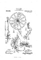
Figure 1, is a perspective view showing the complete arrangement of my invention,
the same being shown as a marine merry-goround. Fig. 2, 1s a transverse section of the same, all of the parts back of the center Vbeing omitted to the more clearly illustrate the arrangement of an opposite pair of cars and their connections with the rotator or spider frame. Fig. 3, is a detail section on` an enlarged scale, of the center or base bearing for the spider frame and the center post. Figs. 4, 5 and 6, are detail views of several parts hereinafter specifically referred to. Fig. 7 is a detail perspective view that illustrates one of the cars, its rail mount, and the flexibly connected bridge that joins the car with the spider frame, or attendants platform. Fig. 8, is a detail cross section showing the rail and the track sheave and guard sheave. Fig. 9, is a longitudinal section of the bridge and its connection with the car and the spider platform. Fig. 10, is a diagrammatic plan view of the spider frame, the cars and car tracks and the bridge connections therefor. Fig. 11, shows a slightly modified arrangement, the bridge construction hereinafter fully referred to and Fig. 12, is a detail cross section on the line 12-12 on Fig. 9.
ln carrying out my invention, the center or main pole 1 of the apparatus has its lower end mounted in a hub 2 secured to cross or bed timbers 3, the upper end of the pole being braced by the stay rods 4-4 that connect to a cap piece 10 and to eye bolts 50 on the upper end of a series,-four being shown, of outside poles 5 that are firmly anchored in the ground.
Mounted on the pole 1, is the rotator or spider frame, which consists of a series of radially projected arms 6-6 the inner end of each of which is bolted to an apertured l hub 7 that has a pendent circular iiange 70 to seat and turn in a socket 20 in the top of the main hub 2, as is best shown in Fig. 3. Each of the spider arms 6, is further braced by a hanger rod 8, adjustably joined with the arms 6, by the nuts SO, engaging the lower or threaded ends of said rods 8, see Fig. et, and each of the said rods 8 has a hook 81 at the upper end for engaging the apertured flange 91 of a disk 9, that is clamped or otherwise made fast on the upper end of a tubular shaft 12 that rotates on the pole 1 and has its lower end clamped in the hub 7 to turn therewith, by the clamp screws 75, as clearly shown in Fig. 3.
13 designates the master or drive wheel secured to the under side of the spider frame that receives the power. or driven belt or cable 14, driven in any well known manner.
From the foregoing,the general const-ruction and the `manner of operating the spider or rotator frame will be readily apparent, it being obvious that as power is applied to the cable, the spider frame with its hanger or braces will be moved around.
The cars or boats and the tracking construction which forms the essential features of my invention, are best understood by referring to Figs. 1, 2 and 10 of the drawings by reference to which it will be seen, that with the rotator or spider frame join a number of carriages that hold the occupants, and each of the said carriages joins with the said rotator frame by a bridge member that joins the cars with the annular walk or way 65 on which the attendant walks in passing from one car or bridge to the other while collecting the fares.
Each of the carriages or cars 15, has a track sheave 16 at the front and a similar sheave 16a at the rear and each of the sheaves has a deep groove lb for firmly straddling and riding the substantially circular trackway, the peculiar construction and ar rangement of which forms an essential feature of my invention.
The trackway consists of two rail plates, an outer one 17 and an inner one 17a, the upper edges of the two being in the same plane, the lower end of plate 17a extending below plate 17 to form an inverted rail 17X for receiving the guard sheave 16c that has a deep groove to straddle rail 17X, sheave 16C revolves on a stub journal 18 on the lower end of a bracket arm 19, integral with one of a pair of straddle brackets 19a-19a secured to the front of the car and which receive between them the guide wheels 16---16C and in which the journals 16d of said wheels are mounted. To aid in maintaining the cars in their upright or vert-ical position, the journals 16d and 18 radiate from the axial line of the rotation or spider frame. To deaden sound as the sheaves travel over the rails, the several sheaves have rubber or other tires 16f, mounted within their deep grooves as is clearly shown in Fig. 8.
Each car is flexibly joined to the rotator or spider frame by a bridge member 25, it being understood that all of the bridge members radiate from the spider frame and one of such members is provided for each car.
By referring now more particularly to Figs. 7 9, it will be noticed each bridge member 25 is hinged at the inner end to the peripheral edge of the spider frame or attendants platform, so it can swing in the vertical plane and at the outer end and centrally thereof is an eye-bolt 26 for loosely engaging an eye bolt 27 secured to the adjacent side of the car. To brace the bridge member side stay rods 28-28, that are swivelly secured at their inner ends to the spider or rotator frame, adjustably join with the pendent brackets 29, 29 on the under side of the outer end of the bridge 25, one of said brackets being at each side of the swivel joint that connects the bridge with the car. To protect the attendant when passing up the bridge Vmembers and while collecting fares, side rails 25a-25a are provided.
Instead of making it necessary for the attendant to walk up the bridge to collect fares and to avoid all possible danger of accident while so doing, a collector may be used on each bridge, in the nature of a farebox 35 on an endless cable 36 on one of the guard rails or the bridge, see Fig. 11.
In an apparatus of this kind, it is greatly desired that the cars maintain, as nearly as possible, a perfect vertical equilibrium as they are swiftly carried around and up and down the undulated trackway, for the reason that a large percentage of the accidents, especially throwing occupants out of the cars, is caused by sudden lateral vibrations or jars on the carsl as they swift-ly move on' a circular path.`
As heretofore described, the cars are each swivelly joined to their respective bridge members, such joint allowingy the cars to have perfect freedom of longitudinal oscillation and such slight swaying necessary to avoid binding of their connection with the bridge members as the cars rise Vand fall as they pass over the undulated trackway.
Since the relative distance of the cars from the axial line of the rotator or spider frame changes as the cars rise or lower from the normal line, provision must be had for compensating for such changes in distance, so the cars will be sustained in the vertical plane when at their highest or lowest position. In my construction of merrygoround, I have a special construction of the track-way for the cars that provides for sustaining the cars at the vertical position as they pass above or below the normal line of travel. By referring now to Fig. 10, which is a diagrammatic representation of the apparatus, the dotted line Y, designates the normal line of travel and the normal distance of the cars from the axis of the rotator or spider frame. Since any rise or drop of the cars from the normal would increase the distance between cars and the spider fra-me, if the t-rackway were in a true circle and hence break the connections between the cars and the spider frame, I arrange the trackway as shown in Fig. 10, the special arrangement being best explained as follows.
Assuming the car ato be in a normal position, in a plane with the platform 65, see Fig 9, and to be traveling in. the direction of the arrow, (said special car being also indicated by a in Fig. 1) and to be descending into the pond or low point. From the point of descent, the-track rail gradually curves inwardly until the point of greatest depth is reached, when it again gradually curves outwardly to the normal circular line, it continuing on such circular line so long as the car travels in the normal path. So soon as the car begins to rise, the trackway again begins to curve inwardly and continues so until the car reaches the highest point and begins to descend to normal line when the track again begins to curve out to the normal or circular line, it being understood that the degree of curvature from or to the normal line of trackway accords with the amount of the rise and fall of the car from the normal and always sufficient to maintain the same distance between the car and the axis of the spider frame. ,The lateral curvature or undulations of the trackway also adds to the amusement and sensations, since the car is caused to take lateral curvatures while going up or down, and have both motions while maintaining, at all times, a substantially vertical position.
Various modifications in the forms of the cars and the degree of undulations of the trackway and arranging the whole in other attractive manner than that shown may be made without departing from the spirit of my invention or the scope of 'the appended claims.
Having thus described my invention, what I claim and desire to obtain by Letters Patent, is:
l. In an amusement apparatus, a vertically and horizontally undulating ring like track, a car running on said track, means for maintaining the car on the said track, a centrally disposed rotatable element and connections between the said element and the car.
2. An amusement apparatus, comprising a central rotatable element, radial sweeps pivotally connected thereto, a car joined to each sweep, sheaves on the car, a vertically and horizontally undulated trackway engaged by the said sheaves and a compensating means for maintaining a uniform distance between the car and the rotatable clement as the cars rise and fall on the undul-ated trackway'.
3. An amusement apparatus comprising a circular vertically undulating trackway, the undulated portions being progressively horizontally curved with respect to the rise and fall of the undulations in the track, a centrally disposed rotator, radial sweeps joined thereto, and cars connected to the sweeps, said ears having sheaves for engaging the undulating trackway.
4. In an amusement apparatus, a ringlike trackway having vertical and horizontal undulations, a centrally disposed rotatable element, a car running on said track and a fixed connection between said car and said rotatable element.
5. In an amusement apparatus, a vertically and horizontally undulated ring-like track, a car running on the said track, a centrally disposed element and swivel connections that join the said element and the car.
6. In an amusement apparatus, a vertically and horizontally undulated ring-like track, a car running on said track, a centrally disposed rotary element, a sweep hinged to the said element to swing vertically and a swivel connection that joins the car and the said sweep.
7. In an amusement apparatus, a vertically and horizontally nndulated ring-like track, a car running on the track, means for maintaining the car on the track, a centrally disposed rotary frame having an annular platform, a bridge hinged to the platform to swing vertically and a swivel connection that joins the bridge and the car.
S. An amusement apparatus, a vertically and horizontally undulated ringlike track, a car running on the track, a centrally disposed rotatable horizontal frame having an annular platform, a bridge member hinged to the said platform and extended radially therefrom and a swivel connection that joins the bridge member and the car.
MERRITT WESLEY PALMER.
Witnesses:
EUGENE D. NASH, HERMAN BnowER.
Copies of this patent may be obtained for ve cents each, by addressing the Commissioner of Patents,
Washington, D. C.
Priority Applications (1)
| Application Number | Priority Date | Filing Date | Title |
|---|---|---|---|
| US57609110A US989280A (en) | 1910-08-08 | 1910-08-08 | Merry-go-round. |
Applications Claiming Priority (1)
| Application Number | Priority Date | Filing Date | Title |
|---|---|---|---|
| US57609110A US989280A (en) | 1910-08-08 | 1910-08-08 | Merry-go-round. |
Publications (1)
| Publication Number | Publication Date |
|---|---|
| US989280A true US989280A (en) | 1911-04-11 |
Family
ID=3057618
Family Applications (1)
| Application Number | Title | Priority Date | Filing Date |
|---|---|---|---|
| US57609110A Expired - Lifetime US989280A (en) | 1910-08-08 | 1910-08-08 | Merry-go-round. |
Country Status (1)
| Country | Link |
|---|---|
| US (1) | US989280A (en) |
Cited By (2)
| Publication number | Priority date | Publication date | Assignee | Title |
|---|---|---|---|---|
| US4960275A (en) * | 1989-11-06 | 1990-10-02 | Imrych Magon | Water immersion amusement apparatus |
| WO2019081077A1 (en) * | 2017-10-27 | 2019-05-02 | Mack Rides Gmbh & Co. Kg | Amusement ride |
-
1910
- 1910-08-08 US US57609110A patent/US989280A/en not_active Expired - Lifetime
Cited By (3)
| Publication number | Priority date | Publication date | Assignee | Title |
|---|---|---|---|---|
| US4960275A (en) * | 1989-11-06 | 1990-10-02 | Imrych Magon | Water immersion amusement apparatus |
| WO2019081077A1 (en) * | 2017-10-27 | 2019-05-02 | Mack Rides Gmbh & Co. Kg | Amusement ride |
| US11090572B2 (en) | 2017-10-27 | 2021-08-17 | Mack Rides Gmbh & Co. Kg | Amusement ride |
Similar Documents
| Publication | Publication Date | Title |
|---|---|---|
| US792422A (en) | Pleasure-railway. | |
| US989280A (en) | Merry-go-round. | |
| US472211A (en) | Half to louis a | |
| US928435A (en) | Elevated suspended-track automotor-railway. | |
| US1074185A (en) | Pleasure-railway. | |
| US609164A (en) | Roller-coaster | |
| EP2498883A1 (en) | Device for aerial amusement rides | |
| US263243A (en) | Circular railroad or roundabout | |
| US863362A (en) | Amusement device. | |
| US1334727A (en) | Pleasure-machine | |
| US259569A (en) | Wind-motor | |
| US1660012A (en) | Amttseheirii device | |
| US820118A (en) | Amusement apparatus. | |
| US1295145A (en) | Amusement device. | |
| US1751096A (en) | Coasting apparatus | |
| US878400A (en) | Amusement device. | |
| US372296A (en) | blinkhoen | |
| US773831A (en) | Roundabout. | |
| US736225A (en) | Revolving circular track. | |
| US623667A (en) | James c | |
| US5370583A (en) | Thrill ride apparatus | |
| US382347A (en) | Elevated street-raj lway system | |
| US1065783A (en) | Roundabout. | |
| US774757A (en) | Circle-swing. | |
| US625074A (en) | weber |