US9407904B2 - Method for creating 3D virtual reality from 2D images - Google Patents
Method for creating 3D virtual reality from 2D images Download PDFInfo
- Publication number
- US9407904B2 US9407904B2 US14/709,327 US201514709327A US9407904B2 US 9407904 B2 US9407904 B2 US 9407904B2 US 201514709327 A US201514709327 A US 201514709327A US 9407904 B2 US9407904 B2 US 9407904B2
- Authority
- US
- United States
- Prior art keywords
- image
- images
- regions
- depth information
- viewer
- Prior art date
- Legal status (The legal status is an assumption and is not a legal conclusion. Google has not performed a legal analysis and makes no representation as to the accuracy of the status listed.)
- Expired - Fee Related
Links
Images


Classifications
-
- H04N13/0271—
-
- H—ELECTRICITY
- H04—ELECTRIC COMMUNICATION TECHNIQUE
- H04N—PICTORIAL COMMUNICATION, e.g. TELEVISION
- H04N13/00—Stereoscopic video systems; Multi-view video systems; Details thereof
- H04N13/20—Image signal generators
- H04N13/271—Image signal generators wherein the generated image signals comprise depth maps or disparity maps
-
- G—PHYSICS
- G06—COMPUTING; CALCULATING OR COUNTING
- G06T—IMAGE DATA PROCESSING OR GENERATION, IN GENERAL
- G06T15/00—3D [Three Dimensional] image rendering
- G06T15/10—Geometric effects
- G06T15/20—Perspective computation
- G06T15/205—Image-based rendering
-
- G—PHYSICS
- G06—COMPUTING; CALCULATING OR COUNTING
- G06T—IMAGE DATA PROCESSING OR GENERATION, IN GENERAL
- G06T17/00—Three dimensional [3D] modelling, e.g. data description of 3D objects
-
- H04N13/0018—
-
- H04N13/0022—
-
- H04N13/026—
-
- H—ELECTRICITY
- H04—ELECTRIC COMMUNICATION TECHNIQUE
- H04N—PICTORIAL COMMUNICATION, e.g. TELEVISION
- H04N13/00—Stereoscopic video systems; Multi-view video systems; Details thereof
- H04N13/10—Processing, recording or transmission of stereoscopic or multi-view image signals
- H04N13/106—Processing image signals
- H04N13/122—Improving the 3D impression of stereoscopic images by modifying image signal contents, e.g. by filtering or adding monoscopic depth cues
-
- H—ELECTRICITY
- H04—ELECTRIC COMMUNICATION TECHNIQUE
- H04N—PICTORIAL COMMUNICATION, e.g. TELEVISION
- H04N13/00—Stereoscopic video systems; Multi-view video systems; Details thereof
- H04N13/10—Processing, recording or transmission of stereoscopic or multi-view image signals
- H04N13/106—Processing image signals
- H04N13/128—Adjusting depth or disparity
-
- H—ELECTRICITY
- H04—ELECTRIC COMMUNICATION TECHNIQUE
- H04N—PICTORIAL COMMUNICATION, e.g. TELEVISION
- H04N13/00—Stereoscopic video systems; Multi-view video systems; Details thereof
- H04N13/20—Image signal generators
- H04N13/261—Image signal generators with monoscopic-to-stereoscopic image conversion
Definitions
- One or more embodiments of the invention are related to the field of image analysis and image enhancement, and computer graphics processing of two-dimensional (2D) images into three-dimensional (3D) stereoscopic images. More particularly, but not by way of limitation, one or more embodiments of the invention enable a method for creating 3D virtual reality environments from 2D images.
- One or more 2D images of a scene are obtained and are converted to a format that provides three-dimensional views for use in a virtual reality environment. These three-dimensional views may be generated dynamically based on the viewer's position and orientation in the virtual reality environment by applying depth information associated with the scene. Depth information may be accepted by the system for regions in raster or vector format or obtained externally and utilized in the conversion process.
- 3D viewing is based on stereographic vision, with different viewpoints from one or more images provided to the left and right eyes to provide the illusion of depth.
- Many techniques are known in the art to provide 3D viewing.
- specialized glasses may be utilized for viewing 3D images, such as glasses with color filters, polarized lenses, or anamorphic lenses.
- Some 3D viewing methods use separate screens for left eye and right eye images, or project images directly onto the left eye and right eye.
- Virtual reality environments typically are computer-generated environments that simulate user presence in either real world or computer-generated worlds.
- the systems utilized to display the virtual reality environment typically include a stereoscopic display for 3D viewing and generally instrument a viewer with one or more sensors, in order to detect and respond to the position, orientation, and movements of the viewer. Based on these values, the virtual reality environment generates images to provide an immersive experience.
- the immersive experience may also include other outputs such as sound or vibration. Images may be projected onto screens, or provided using specialized glasses worn by the user.
- the primary challenge with creating a 3D virtual reality environment is the complexity of generating the necessary stereo images for all possible positions and orientations of the viewer. These stereo images must be generated dynamically in approximately real-time as the viewer moves through the virtual reality environment. This requirement distinguishes 3D virtual reality from the process of generating 3D movies from 2D images as the location of the viewer is essentially fixed at the location of the camera.
- Embodiments of the invention enable a method for creating 3D virtual reality from 2D images.
- a set of 2D images may be obtained from an environment, which may for example be a real physical environment such as a room, a computer-generated environment, or a mix of physical and computer-generated elements.
- 2D images may be captured using a camera aimed at various angles to form a panoramic collection of images covering a desired part of a scene.
- the collection of images may cover an entire sphere, providing 360° viewing in all directions (including left-to-right and up and down).
- Embodiments of the invention enable converting these 2D images into a 3D virtual reality experience.
- a viewer in the virtual reality environment may be able to view the environment from various locations and orientations, and perceive three-dimensional depth reflecting the physical or modeled characteristics of the captured scene.
- subsets of the 2D images are first stitched together, using for example common features or overlapping pixels.
- the integrated, stitched images may then be projected onto a spherical surface to form a complete 360 degree view of the scene (or a desired portion thereof) in any direction (left to right as well as up and down).
- the spherical surface provides a complete spherical view of the scene, but this view is still two-dimensional since it lacks any depth information.
- Embodiments of the invention enable addition of depth information to the spherical display.
- the spherical surface image is unwrapped onto a plane. This unwrapped image may be divided into regions to assist in generating depth information.
- Depth information is generated for the points of the regions.
- Depth information may comprise for example, without limitation, depth maps, bump maps, parallax maps, U maps, UV maps, disparity maps, ST maps, point clouds, z maps, offset maps, displacement maps, or more generally any information that may provide a three-dimensional shape or three-dimensional appearance to an image.
- 3D stereoscopic images may be generated for a viewer in a 3D virtual reality environment. The depth information determines the amount of offset for each point between the left eye and right eye images, which provides a three-dimensional viewing experience.
- the depth information may be projected onto a sphere, yielding spherical depth information that provides depth for all or a portion of the points on the sphere.
- Spherical depth information may comprise for example, without limitation, spherical depth maps, spherical bump maps, spherical parallax maps, spherical U maps, spherical UV maps, spherical disparity maps, spherical ST maps, spherical point clouds, spherical z maps, spherical offset maps, spherical displacement maps, or more generally any information that may provide a three-dimensional shape or three-dimensional appearance to a spherical surface.
- the unwrapped plane image is also projected onto a spherical surface to form the spherical image. Left and right eye images may then be generated using the spherical depth information.
- the spherical depth information may be a spherical depth map that provides a z-value for each point on the sphere.
- left and right images may be formed by projecting each image point from its spherical depth position onto left and right image planes.
- the position and orientation of the left and right image planes may depend on the position and orientation of the viewer in the virtual reality environment.
- the projections from the spherical depth map points onto the left and right image planes may for example use standard 3D to 2D projections to a plane using a different focal point for each eye.
- a different method may be used to generate the stereographic images.
- This method first generates a stereo image in 2D using the unwrapped plane image and the plane depth information.
- the left and right images are then projected onto spheres, with a separate left sphere and right sphere for the left and right images.
- left and right image planes and eye positions are calculated, the left sphere is projected onto the left image plane, and the right sphere is projected onto the right image plane.
- the regions of the unwrapped plane image may be used to assist in creating the depth information.
- One or more regions may be mapped onto flat or curved surfaces, and these surfaces may be positioned and oriented in three-dimensional space.
- constraints may be applied manually or automatically to reflect continuous or flexible boundaries between region positions in space.
- Depth information may be generated directly from the region positions and orientations in three-dimensional space by relating the depth to the distance of each point from a specified viewpoint.
- objects may be captured in the 2D images that should not appear in the virtual reality environment; conversely it may be desirable to insert additional objects that were not present in the 2D images.
- Operators may edit the original images, the unwrapped 2D image, the spherical images, or combinations of these to achieve the desired effects.
- Removing an object from the environment consists of replacing the pixels of the removed object with a suitable fill, which may be obtained automatically from surrounding regions.
- Adding an object consists of inserting an image and applying the appropriate depth information to the region or regions of the added image.
- Inserted images may be obtained from real objects or they may be computer generated, or they may be a combination of real images and computer generated images.
- Objects in the 2D images may also be extended in some embodiments to fill areas that were not captured in the original images, or that are in areas where undesired objects have been removed.
- Some embodiments may add objects in multiple layers at multiple depths, providing for automatic gap filling when the viewpoint of a viewer in the 3D virtual reality environment changes to reveal areas behind the original objects in the scene.
- FIG. 1 illustrates a flowchart of at least one embodiment of a method for creating 3D virtual reality from 2D images.
- FIG. 1A illustrates a flowchart of at least one embodiment of a method for generating 3D virtual reality in which stereo images are generated using spherical depth information that positions 2D pixels relative to the surface of a sphere in 3D space.
- FIG. 1B illustrates a flowchart of at least one embodiment of a method for generating 3D virtual reality in which stereo images are generated first in 2D, then projected onto separate left and right spheres, and finally converted to stereo in a 3D viewing environment.
- FIG. 2 illustrates an embodiment of a step to capture a series of 2D images of an environment by aiming a camera in varying horizontal and vertical angles.
- FIG. 3 illustrates an embodiment of a step to stitch sets 2D images together into integrated 2D images; in this illustration four 2D images from FIG. 2 are stitched together into an integrated image by aligning matched features.
- FIG. 4 illustrates an embodiment of a step to project integrated 2D images onto a spherical surface.
- FIG. 5 illustrates an example of a spherical surface image that results from projecting 2D images onto a sphere.
- FIG. 6 illustrates an example of a spherical surface image that is unwrapped into a panoramic 2D image. (Note that this scene is different from the scene shown in FIG. 5 .)
- FIG. 7 illustrates an embodiment of a step of dividing the unwrapped image of FIG. 6 into multiple regions; each region is color-coded with a color mask to identify its boundaries.
- FIG. 8 illustrates an embodiment of a step of assigning a depth map to the points of each of the regions of FIG. 7 ; darker points are closer to the viewer.
- FIG. 9 illustrates an anaglyph 3D stereoscopic view of the scene depicted in FIG. 7 with the depth map of FIG. 8 .
- FIG. 10 illustrates an embodiment of a step of creating a spherical depth map from a 2D depth map as outlined in the flowchart of FIG. 1A .
- FIG. 11 illustrates an embodiment of a step of generating left and right stereo 2D views from a spherical depth map.
- FIG. 12 illustrates an embodiment of a step of generating separate left and right spherical surface images, which are subsequently used to create stereo views, using a 2D image and a 2D depth map, as outlined in the flowchart of FIG. 1B .
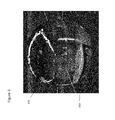
- FIG. 13 illustrates an embodiment of a division of a 2D image of a human figure into regions, with each region assigned a distinct color for identification.
- FIG. 14 illustrates an embodiment of positioning and orienting the regions of FIG. 13 in 3D space in order to generate depth information.
- FIG. 15 illustrates an embodiment of a depth map generated from the 3D model of FIG. 14 .
- FIG. 16 illustrates the 2D images captured from a scene as shown in FIG. 2 , highlighting features where modifications are desired to the images in order to form the 3D virtual reality environment.
- FIG. 17 illustrates an unwrapped image formed from the 2D images of FIG. 16 with the desired modifications made to the image.
- FIG. 1 illustrates a flowchart of at least one embodiment of a method for creating 3D virtual reality from 2D images, including exemplary components that may be utilized therewith.
- step 101 multiple 2D images are obtained of environment 100 , yielding a set of 2D images 102 .
- Environment 100 may for example be a room, an office, a building, a floor, a house, a factory, a landscape, or any other scene or combination of scenes for which a virtual reality experience is to be created.
- This environment may be real, or it may itself be virtual or computer generated, or it may be a mix of real elements and computer generated elements.
- the step 101 of obtaining 2D images may use for example one or more cameras—including single image and video cameras—or any other sensor or sensors that capture non-visible frequencies such as radar or lidar.
- the cameras may be virtual and the 2D images may be viewing projections of a 2D or 3D computer generated scene.
- the depth information associated with an image may be accepted by the system, for example by providing user interface elements for users to draw masks on regions or user interface elements to set parameters for auto-generation of masks for regions of luminance, color or other image parameters.
- the system thus enables the user to assign depth information to regions in the 2D image or alternatively or in combination, obtain depth via radar or lidar to generate a depth map for example.
- Step 103 stitches together subsets of the 2D images 102 into integrated 2D images 104 .
- the stitching process combines and aligns 2D images and eliminates overlap among the 2D images.
- Stitching step 103 may combine all 2D images into a single panorama, or it may combine subsets of 2D images into various panoramic images that cover portions of the entire environment 100 .
- Different embodiments may employ different stitching strategies.
- Integrated images may cover all or any portion of the sphere of view directions visible from one or more cameras.
- Stitching may be done manually, automatically, or with a hybrid manual-automatic procedure where one or more operators make rough stitching and software completes the smooth stitch.
- Embodiments of the invention may utilize any or all of these approaches.
- Automated stitching typically aligns the overlap regions of multiple images using a best-fit based on feature differences or on pixel differences.
- Feature-based methods perform a feature extraction pass first on the images, and then find the location of similar features in multiple images for alignment. See for example: M. Brown and D. Lowe (2007). Automatic Panoramic Image Stitching using Invariant Features. International Journal of Computer Vision, 74(1).
- Pixel-based methods minimize the pixel differences between images in their regions of overlap. See for example: Suen et al. (2007). Photographic stitching with optimized object and color matching based on image derivatives. Optics Express, 15(12).
- step 105 the integrated 2D images 104 are projected onto a spherical surface.
- these projections may use a measured or estimated position and orientation of the camera or cameras used in step 101 to capture the 2D images that formed the integrated 2D images.
- the output of step 105 is a spherical surface image 106 .
- a spherical surface represents an approximate 3D model of the location of the objects in the environment 100 ; this approximate model places all points on the objects equidistant from the center of the sphere. Adjustments to this approximate 3D model may be made in subsequent steps using depth information to form more realistic models of the environment.
- step 107 the spherical surface image 106 is “unwrapped” onto an unwrapped plane image 108 .
- This unwrapping process may use any of the spherical-to-plane projection mappings that are known.
- step 109 the unwrapped plane image 108 is divided into regions 110 .
- This step may be done by one or more operators, or it may be assisted by software. For example, software may tentatively generate region boundaries based on shapes, colors, or textures of objects in the unwrapped image 108 .
- depth information 112 is assigned to the points of the regions 110 .
- the depth information is used in subsequent steps to generate the 3D stereo images for a virtual reality experience.
- Depth information reflects how far away each point of each region is from a viewer.
- Many techniques for defining and using depth information are known in the art; any of these techniques may be used for generating or using the depth information 112 .
- depth information may comprise depth maps, bump maps, parallax maps, U maps, UV maps, disparity maps, ST maps, point clouds, z maps, offset maps, displacement maps, or more generally any information that may provide a three-dimensional shape or three-dimensional appearance to an image. Assigning of depth information may be done by one or more operators.
- software may be used to assist the step 111 of assigning depth information. For example, operators may be able to rotate or reposition entire regions in a 3D scene, and depth information may be generated automatically for the regions based on this 3D positioning. Software may also be used to generate curved regions or to blend depth information at boundaries between regions.
- the depth information 112 and the unwrapped image 108 are used as inputs to generate stereo images for a viewer at viewer position and orientation 113 .
- the stereo images consist of a left eye image 115 and a right eye image 116 .
- Any of the commonly available stereo 3D vision technologies such as special viewing glasses used to see 3D movies, may be used by the viewer to view the virtual reality environment in 3D using these stereo images.
- viewers may use glasses with different colored left and right lenses, or glasses with different polarization in left and right lenses, or glasses with LCD lenses that alternately show left and right images.
- FIGS. 2-9 illustrate exemplary embodiments of the steps of FIG. 1 in greater detail, while FIGS. 1A and 1B are discussed after FIGS. 2-9 .
- FIG. 2 illustrates an embodiment of step 101 —obtaining 2D images of environment 100 .
- the environment 100 is a room with a table 203 approximately in the center of the room.
- a series of 2D images 201 is obtained of the room using a camera aimed at different angles.
- the 2D images 201 are captured in five rows 202 a , 202 b , 202 c , 202 d and 202 e , where each row corresponds to a vertical angle for the camera. Within each row the camera is aimed at 12 different horizontal angles, with an increment 204 of approximately 30° between each horizontal angle, forming a complete 360° panorama of the scene 100 .
- Other embodiments of the invention may use different techniques and angle increments for capturing a series of 2D images to cover a desired portion of an environment 100 .
- FIG. 3 illustrates an embodiment of step 103 —stitching together 2D images into integrated images.
- Image 301 , 302 , 303 , and 304 are individual 2D images from row 202 e of FIG. 2 .
- a manual or automated scan for shared features identifies, for example, the back of the chair which appears as 305 a in image 301 and as 305 b in image 302 , and the right front table leg which appears as 306 a in image 303 and as 306 b in image 304 . Aligning the images on these (and other) shared features produces the rough stitch 307 .
- Different embodiments of the invention may use various grouping strategies for stitching together integrated images in step 103 .
- all of the images in a row may be stitched together, or portions of rows (as shown here in FIG. 3 ) may be stitched together.
- Stitching may also be done vertically (in columns) in addition to or instead of horizontally (in rows), or with mixed approaches to combine similar images.
- FIG. 4 illustrates an embodiment of step 105 —projecting the integrated 2D images onto spherical surface 403 .
- Many techniques are known in the art for projecting plane images onto a sphere and for the reverse process of projecting spherical images onto a plane. These techniques are similar to known techniques of cartography, which generate 2D map images of a spherical surface or a portion thereof.
- maps may use projections such as Mercator, Lambert cylindrical, Azimuthal, Orthographic, and many others. Projecting 2D plane images onto a sphere amounts to reversing the normal map projections that project a sphere onto plane images.
- FIG. 4 illustrates a spherical projection that may be used in one or more embodiments of the invention.
- each 2D image is considered to be a plane perspective projection of a spherical surface using a fixed point of perspective for the projection.
- the projection of the 2D image to the sphere simply reverses the perspective projection.
- Multiple images may be projected to the same spherical surface using location and orientation of the camera when each image was captured.
- 2D images 401 and 402 are projected onto the sphere 403 .
- Sphere 403 has center point c 404 , and radius R 405 .
- Image 401 was obtained using a camera with a viewer located at point v 1 406 ;
- image 402 was obtained using a camera with a viewer located at point v 2 410 .
- the orientation of the planes of images 401 and 402 correspond to the orientation of the cameras used to capture those images.
- Each point on the 2D images 401 and 402 is projected to the sphere along a ray from the camera's viewer. For example, point p 407 is projected onto point q 408 on sphere 403 .
- FIG. 5 illustrates a spherical projection of the 2D images from FIG. 2 . Images are projected onto spherical surface 501 . For example, the 2D table image 203 from FIG. 2 appears as image 502 on sphere 501 .
- FIG. 6 illustrates an unwrapped image obtained from a spherical projection via step 107 —unwrap onto plane image. Converting the spherical image to a plane unwrapped image amounts to reversing the projections illustrated in FIG. 4 using a single projection of the sphere onto a plane. Note that the scene illustrated in FIG. 6 is not the same scene illustrated in FIGS. 2 and 4 . In this unwrapped image the straight edges of the rug appear as curved lines such as 601 .
- the unwrapped image is a 360 degree panorama; for example the left edge 602 a of the chair corresponds to the right edge 602 b.
- FIG. 7 illustrates an embodiment of step 109 —dividing the unwrapped image into regions—applied to the unwrapped image of FIG. 6 .
- Each region is indicated by a different color mask.
- the blue mask 701 defines the rug in the center of the room.
- the system may enable the user to define masks for regions in the image and accept input for the masks by an operator, for example by implementing software on a computer system specifically for that purpose, or using a combination of methods.
- the rug 601 in FIG. 6 has a distinct color and pattern that may used to automatically or semi-automatically identify the blue mask region 701 in FIG. 7 .
- the system may thus enable the user to input a foreground distance and background distance for mask region 701 for example.
- radar or lidar may be obtained and utilized to auto generate depths for portions or the entire image or masks or regions therein.
- FIG. 8 illustrates an embodiment of step 111 —generating depth information for the points of the regions defined in step 109 .
- the depth information is encoded as a depth map, with points closer to the viewer shown with darker shades of grey, and points further from the viewer shown with lighter shades of grey.
- the front edge 801 of the table in the center of the room has a dark shade since it is close to a viewer in or near the center of the room; the wall 802 behind the couch has a lighter shade since it is further from the viewer.
- Operators may assign depth information to individual pixels, or they may use the region masks to assist in defining depth information by positioning and rotating the regions in three dimensional space. Numerical depth information that is not visible, for example compressed or encoded may also be utilized.
- FIG. 9 illustrates an embodiment of step 114 —generating stereo images.
- the unwrapped image from FIG. 6 is combined with the depth map from FIG. 8 to generate left and right eye images, which are superimposed here on the same anaglyph image.
- This anaglyph image provides a 3D stereoscopic view of the scene when viewed through anaglyph glasses with different color filters in the two lenses.
- the amount of shift between left eye and right eye images for each pixel is a function of the depth map for that pixel.
- embodiments of the invention may use various techniques in step 114 to generate the stereo images 115 and 116 . As illustrated in FIG. 9 , embodiments may use the depth information 112 to shift the display of pixels in left eye images versus right eye images, with closer pixels being shifted a greater amount.
- FIGS. 1A and 1B illustrate specific techniques that may be used by some embodiments of the invention to perform step 114 .
- FIG. 1A illustrates a technique wherein step 114 comprises two additional steps 120 and 123 .
- step 120 the unwrapped image 108 and the depth information 112 are both projected onto a sphere. This process yields spherical image 121 and spherical depth information 122 .
- FIG. 10 illustrates the generation of a spherical depth map, which is an example of spherical depth information 122 .
- Spherical depth information may comprise for example, without limitation, spherical depth maps, spherical bump maps, spherical parallax maps, spherical U maps, spherical UV maps, spherical disparity maps, spherical ST maps, spherical point clouds, spherical z maps, spherical offset maps, spherical displacement maps, or more generally any information that may provide a three-dimensional shape or three-dimensional appearance to a spherical surface.
- 2D depth map 1001 contains two regions: region 1002 is closer to the viewer (hence shaded darker) and region 1003 is further from the viewer (hence shaded lighter).
- Depth map 1001 is projected via projection 1004 to the sphere 1005 . Regions with greater depth (further from the viewer) are pushed further away from the center of the sphere to form a spherical depth map. Hence spherical region 1006 , corresponding to planar region 1002 , is closer to the center of sphere 1005 than spherical region 1007 , corresponding to planar region 1003 .
- spherical image 121 and spherical depth information 122 are used in step 123 to generate left eye image 115 and right eye image 116 .
- FIG. 11 illustrates this process in greater detail.
- Viewer 1110 is observing a virtual reality scene from a specific position and orientation.
- the viewer 1110 has a left eye position 1111 and a right eye position 1112 .
- 2D images and a 2D depth map have been projected onto sphere 1005 .
- the image contains black colored region 1101 , which is located near the center of the sphere, and speckled region 1102 , which is located far from the center of the sphere.
- the left eye image is formed by projecting points from the sphere onto the left eye plane 1113 a ; similarly the right eye image is formed by projecting points from the sphere onto the right eye plane 1114 a .
- the center point of region 1101 is projected onto point 1115 a in the left eye plane, and onto point 1117 a in the right eye plane.
- the center point of region 1102 is projected onto point 1116 a in the left eye plane, and onto point 1118 a in the right eye plane.
- left eye image 1113 b and of the right eye image 1114 b show that the relative shift of the regions 1101 and 1102 depends on the depth of each region on the spherical depth map:
- Left eye image 1115 b of region 1101 is offset significantly from right eye image 1117 b of region 1101
- left eye image 1116 b of region 1102 is only slightly offset from right eye image 1118 b of region 1102 .
- FIG. 1B illustrates a different technique for forming left and right eye images that may be used by one or more embodiments of the invention.
- this technique first forms planar stereo images and then projects these onto left and right spheres.
- This is an alternative technique to that shown in FIG. 1A , which first projects onto a sphere, and then forms stereo images thereafter.
- the unwrapped planar image 108 is combined with the depth information 112 to form a left unwrapped image 131 and a right unwrapped image 132 .
- Each of the unwrapped images 131 and 132 is then projected onto a sphere, forming a left sphere 135 and a right sphere 136 .
- the spheres 135 and 136 are projected on left eye image 115 and right eye image 116 respectively.
- FIG. 12 illustrates an embodiment of the details of steps 130 , 133 and 134 .
- Unwrapped planar image 108 contains regions 1202 and 1203 .
- Depth map 112 assigns a depth 1205 to region 1202 and a depth 1206 to region 1203 ; the darker shading of depth 1206 vs. depth 1205 indicates that object 1203 is closer to the viewer than object 1202 .
- Step 130 combines unwrapped image 108 and depth map 112 to form left unwrapped image 131 and right unwrapped image 132 .
- the left image position 1202 a of object 1202 is offset only slightly from the right position 1202 b of object 1202 based on object 1202 's, whereas the left image position 1203 a of object 1203 is offset considerably from the right position 1203 b of object 1203 .
- These offset differences reflect the depth differences of the objects in depth map 112 .
- the left unwrapped image 131 is projected onto left sphere 135 .
- the right unwrapped image 132 is projected onto right sphere 136 .
- Left planar image 1202 a is projected onto left sphere image 1202 c
- right planar image 1202 b is projected onto right sphere image 1202 d
- left planar image 1203 a is projected onto left sphere image 1203 c
- right planar image 1203 b is projected onto right sphere image 1203 d
- the steps 137 and 138 generate left eye image 115 and right eye image 116 from the spherical images 135 and 136 respectively. Any of the previously described techniques or any other known technique for projecting from a sphere to a plane may be used for these steps 137 and 138 .
- the depth information 112 may be generated by assigning a depth to the points of the regions 110 of the unwrapped image.
- one or more portions of the depth information may be generated by defining a flat or curved surface for one or more of the regions, and positioning and orienting these surfaces in three-dimensional space using rotations and translations.
- the depth information for the points of a region can then be generated automatically using the three-dimensional model of the region surface, simply by picking a view position and calculating the depth of each point as the distance from the view position to the point.
- Some embodiments may use other techniques for calculating depth from a three-dimensional model, such as using orthogonal projections instead of point projections, or using nonlinear scaling between distance and depth.
- FIGS. 13 through 15 illustrate an embodiment of this procedure for positioning and orienting region surfaces or masks.
- Embodiments of the invention may utilize any and all methods and apparatus described in U.S. patent application entitled “EXTERNAL DEPTH MAP TRANSFORMATION METHOD FOR CONVERSION OF TWO-DIMENSIONAL IMAGES TO STEREOSCOPIC IMAGES”, U.S. Ser. No. 13/874,625, filed 1 May 2013, the specification of which is hereby incorporated herein by reference.
- FIG. 13 a 2D image of a human figure is divided into regions. Each region is assigned a distinct color for identification. Region 1301 is one side of the figure's chest; region 1302 is the front of the figure's neck.
- Region 1301 is one side of the figure's chest; region 1302 is the front of the figure's neck.
- each region is positioned and oriented in 3D space.
- Surface 1401 in FIG. 14 corresponds to region 1301 in FIG. 13
- surface 1402 in FIG. 14 corresponds to region 1302 in FIG. 13 .
- the regions 1301 and 1302 may be positioned using the generally noisy depth information as shown in FIG. 14 .
- Surfaces may be flat, or they may be curved surfaces such as for example Bézier surfaces or NURBS surfaces.
- each surface may be positioned or adjusted by an operator using 3D editing or compositing tools.
- software may assist in determining approximate positioning and orientation of each surface, or in applying constraints reflecting joints along surface boundaries.
- steps 109 or 111 or both in FIGS. 1, 1A and 1B embodiments of the invention may obtain the generate regions and/or obtain depth information from an external system or sensor, for example separate from, coupled to or combined with a camera or cameras utilized to obtain the 2D images in step 101 .
- the system may auto-generate masks for the regions within a certain tolerance or curve and calculate best fit for the planar or curved mask in step 109 .
- the surfaces of adjacent regions may be constrained to meet exactly or approximately in 3D space along their boundaries.
- FIG. 15 shows a depth map generated from the 3D positions and orientations of the surfaces in FIG. 14 , for example through use of a function to eliminate noise and/or discontinuities in regions or masks, as performed by accepting user input or through use of smoothing algorithms or any combination thereof. Darker pixels indicate points closer to the viewer. Point 1501 in FIG. 15 has a darker shade than point 1502 , reflecting the positioning of surface 1401 in FIG. 14 closer to the viewer than surface 1402 .
- modifications may be made to the images captured from the scene in order to create a modified 3D virtual reality environment. Such modifications may include additions, deletions, modifications, or any combinations of these changes to the images. Modifications may be made in some embodiments to the original captured 2D images, to the stitched integrated images, to the spherical projection, to the unwrapped plane image, to the depth information, to the stereo images, or to any combinations of these.
- FIGS. 16 and 17 illustrate an embodiment with modifications made to the unwrapped plane image.
- FIG. 16 shows an example of a series of 2D images 201 captured from a scene, as is illustrated also in FIG. 2 .
- Image 1601 contains equipment 1602 that was put in place to capture the images of the scene, as well as an image of an operator who was capturing the scene; it is desired to remove these items from the virtual reality environment.
- Image 1603 shows wall 1604 behind the desk; it is desired to add an image of a person in front of this wall in the virtual reality environment.
- Image 1605 shows a portion of the legs 1606 of the desk, but the 2D images did not capture the entire image of the legs; it is desired to extend these legs to form the complete desk in the virtual reality environment.
- Image 17 illustrates an unwrapped image 1701 formed from the images of FIG. 16 , with the desired modifications made to the unwrapped image.
- Equipment 1602 is removed from 1701 at location 1702 .
- Human FIG. 1703 is inserted into empty area 1604 .
- the table legs 1606 are extended to form complete table legs 1704 .
- These modifications may be made using tools and techniques commonly utilized in the art for photo and image compositing.
- Objects that are inserted or extended require modifications to the unwrapped image, or elsewhere in the processing chain, as well as depth information.
- the composite image and depth information may be generated in multiple layers, so that multiple objects may exist along a radius from the center of the viewing sphere, but at different depth locations. With multi-layered depth information, a viewer in the virtual reality environment may see certain objects exposed as he changes his view position. This technique provides for automatic gap-filling as pixels in the stereographic images are shifted to provide the 3D view.
Abstract
Description
Claims (17)
Priority Applications (3)
| Application Number | Priority Date | Filing Date | Title |
|---|---|---|---|
| US14/709,327 US9407904B2 (en) | 2013-05-01 | 2015-05-11 | Method for creating 3D virtual reality from 2D images |
| US14/827,422 US9288476B2 (en) | 2011-02-17 | 2015-08-17 | System and method for real-time depth modification of stereo images of a virtual reality environment |
| US14/827,482 US9282321B2 (en) | 2011-02-17 | 2015-08-17 | 3D model multi-reviewer system |
Applications Claiming Priority (2)
| Application Number | Priority Date | Filing Date | Title |
|---|---|---|---|
| US13/874,625 US9241147B2 (en) | 2013-05-01 | 2013-05-01 | External depth map transformation method for conversion of two-dimensional images to stereoscopic images |
| US14/709,327 US9407904B2 (en) | 2013-05-01 | 2015-05-11 | Method for creating 3D virtual reality from 2D images |
Related Parent Applications (3)
| Application Number | Title | Priority Date | Filing Date |
|---|---|---|---|
| US13/874,625 Continuation-In-Part US9241147B2 (en) | 2011-02-17 | 2013-05-01 | External depth map transformation method for conversion of two-dimensional images to stereoscopic images |
| US14/827,482 Continuation-In-Part US9282321B2 (en) | 2011-02-17 | 2015-08-17 | 3D model multi-reviewer system |
| US14/827,422 Continuation-In-Part US9288476B2 (en) | 2011-02-17 | 2015-08-17 | System and method for real-time depth modification of stereo images of a virtual reality environment |
Related Child Applications (2)
| Application Number | Title | Priority Date | Filing Date |
|---|---|---|---|
| US14/827,482 Continuation-In-Part US9282321B2 (en) | 2011-02-17 | 2015-08-17 | 3D model multi-reviewer system |
| US14/827,422 Continuation-In-Part US9288476B2 (en) | 2011-02-17 | 2015-08-17 | System and method for real-time depth modification of stereo images of a virtual reality environment |
Publications (2)
| Publication Number | Publication Date |
|---|---|
| US20150249815A1 US20150249815A1 (en) | 2015-09-03 |
| US9407904B2 true US9407904B2 (en) | 2016-08-02 |
Family
ID=54007356
Family Applications (1)
| Application Number | Title | Priority Date | Filing Date |
|---|---|---|---|
| US14/709,327 Expired - Fee Related US9407904B2 (en) | 2011-02-17 | 2015-05-11 | Method for creating 3D virtual reality from 2D images |
Country Status (1)
| Country | Link |
|---|---|
| US (1) | US9407904B2 (en) |
Cited By (18)
| Publication number | Priority date | Publication date | Assignee | Title |
|---|---|---|---|---|
| US20160065949A1 (en) * | 2013-04-02 | 2016-03-03 | Dolby Laboratories Licensing Corporation | Guided 3D Display Adaptation |
| CN106303497A (en) * | 2016-08-12 | 2017-01-04 | 南方科技大学 | A kind of virtual reality content generating method and device |
| US20170372523A1 (en) * | 2015-06-23 | 2017-12-28 | Paofit Holdings Pte. Ltd. | Systems and Methods for Generating 360 Degree Mixed Reality Environments |
| CN108008817A (en) * | 2017-12-01 | 2018-05-08 | 西安枭龙科技有限公司 | A kind of method for realizing virtual reality fusion |
| WO2019021302A1 (en) * | 2017-07-24 | 2019-01-31 | Karthikeyan THANGARAJ | Method of representing shape and color data of 3-d objects |
| US10304234B2 (en) | 2016-12-01 | 2019-05-28 | Disney Enterprises, Inc. | Virtual environment rendering |
| US10453252B2 (en) | 2017-05-08 | 2019-10-22 | Disney Enterprises, Inc. | 3D model construction from 2D assets |
| US20190385274A1 (en) * | 2015-08-12 | 2019-12-19 | Gopro, Inc. | Equatorial stitching of hemispherical images in a spherical image capture system |
| US10839593B2 (en) | 2016-04-08 | 2020-11-17 | Maxx Media Group, LLC | System, method and software for adding three-dimensional images to an intelligent virtual assistant that appear to project forward of or vertically above an electronic display |
| US10957099B2 (en) | 2018-11-16 | 2021-03-23 | Honda Motor Co., Ltd. | System and method for display of visual representations of vehicle associated information based on three dimensional model |
| US11012676B2 (en) | 2017-12-13 | 2021-05-18 | Google Llc | Methods, systems, and media for generating and rendering immersive video content |
| US20210217225A1 (en) * | 2016-03-25 | 2021-07-15 | Outward, Inc. | Arbitrary view generation |
| US11417067B1 (en) | 2020-09-24 | 2022-08-16 | Apple Inc. | Generating a three-dimensional environment based on an image |
| US11477434B2 (en) | 2018-03-23 | 2022-10-18 | Pcms Holdings, Inc. | Multifocal plane based method to produce stereoscopic viewpoints in a DIBR system (MFP-DIBR) |
| US11689709B2 (en) | 2018-07-05 | 2023-06-27 | Interdigital Vc Holdings, Inc. | Method and system for near-eye focal plane overlays for 3D perception of content on 2D displays |
| US11729511B2 (en) | 2019-10-25 | 2023-08-15 | Alibaba Group Holding Limited | Method for wall line determination, method, apparatus, and device for spatial modeling |
| US20230289029A1 (en) * | 2021-10-11 | 2023-09-14 | Angel Studios, Inc. | Visualization |
| US11893755B2 (en) | 2018-01-19 | 2024-02-06 | Interdigital Vc Holdings, Inc. | Multi-focal planes with varying positions |
Families Citing this family (39)
| Publication number | Priority date | Publication date | Assignee | Title |
|---|---|---|---|---|
| KR20160067518A (en) * | 2014-12-04 | 2016-06-14 | 삼성전자주식회사 | Method and apparatus for generating image |
| US10178325B2 (en) * | 2015-01-19 | 2019-01-08 | Oy Vulcan Vision Corporation | Method and system for managing video of camera setup having multiple cameras |
| KR101835434B1 (en) * | 2015-07-08 | 2018-03-09 | 고려대학교 산학협력단 | Method and Apparatus for generating a protection image, Method for mapping between image pixel and depth value |
| KR102458339B1 (en) * | 2015-08-07 | 2022-10-25 | 삼성전자주식회사 | Electronic Apparatus generating 360 Degrees 3D Stereoscopic Panorama Images and Method thereof |
| US10269257B1 (en) * | 2015-08-11 | 2019-04-23 | Gopro, Inc. | Systems and methods for vehicle guidance |
| JP6615545B2 (en) * | 2015-09-15 | 2019-12-04 | 株式会社トプコン | Image processing apparatus, image processing method, and image processing program |
| US9858706B2 (en) | 2015-09-22 | 2018-01-02 | Facebook, Inc. | Systems and methods for content streaming |
| US10096130B2 (en) | 2015-09-22 | 2018-10-09 | Facebook, Inc. | Systems and methods for content streaming |
| CN109074629A (en) | 2015-10-29 | 2018-12-21 | Oy沃肯视觉有限公司 | Video camera is carried out using region of the networking camera to concern |
| WO2017117446A1 (en) * | 2015-12-30 | 2017-07-06 | Daqri, Llc | 3d video reconstruction system |
| CN105530505B (en) * | 2016-01-15 | 2017-06-23 | 传线网络科技(上海)有限公司 | 3-D view conversion method and device |
| US10672180B2 (en) | 2016-05-02 | 2020-06-02 | Samsung Electronics Co., Ltd. | Method, apparatus, and recording medium for processing image |
| CN109314777B (en) | 2016-06-30 | 2021-04-27 | 英特尔公司 | Method and apparatus for virtual reality depth repositioning |
| WO2018048223A1 (en) * | 2016-09-09 | 2018-03-15 | 삼성전자 주식회사 | Method and device for processing three-dimensional image |
| US10783607B2 (en) | 2016-10-06 | 2020-09-22 | Kai Inc. | Method of acquiring optimized spherical image using multiple cameras |
| KR20180051288A (en) * | 2016-11-08 | 2018-05-16 | 삼성전자주식회사 | Display apparatus and control method thereof |
| CN112738531B (en) | 2016-11-17 | 2024-02-23 | 英特尔公司 | Suggested viewport indication for panoramic video |
| CN112702525B (en) * | 2016-11-17 | 2022-05-06 | 英特尔公司 | Encoder, video processing method, system and device |
| CN108154413B (en) * | 2016-12-05 | 2021-12-07 | 阿里巴巴集团控股有限公司 | Method and device for generating and providing data object information page |
| CN108170498B (en) * | 2016-12-05 | 2021-11-02 | 阿里巴巴集团控股有限公司 | Page content display method and device |
| US20210289147A1 (en) * | 2017-01-11 | 2021-09-16 | Intelligent Inventions Limited | Images with virtual reality backgrounds |
| US11158060B2 (en) | 2017-02-01 | 2021-10-26 | Conflu3Nce Ltd | System and method for creating an image and/or automatically interpreting images |
| US11176675B2 (en) * | 2017-02-01 | 2021-11-16 | Conflu3Nce Ltd | System and method for creating an image and/or automatically interpreting images |
| US10582189B2 (en) * | 2017-02-01 | 2020-03-03 | Conflu3nce Ltd. | System and method for generating composite images |
| US11386607B1 (en) * | 2017-04-16 | 2022-07-12 | Meta Platforms, Inc. | Systems and methods for capturing content |
| US10388077B2 (en) | 2017-04-25 | 2019-08-20 | Microsoft Technology Licensing, Llc | Three-dimensional environment authoring and generation |
| KR102628508B1 (en) * | 2017-05-04 | 2024-01-24 | 한국전자통신연구원 | Image processing apparatus and method |
| CN108965917B (en) * | 2017-05-27 | 2021-07-20 | 华为技术有限公司 | Video image presenting and packaging method and video image presenting and packaging device |
| GB2564642A (en) * | 2017-07-10 | 2019-01-23 | Nokia Technologies Oy | Methods and apparatuses for panoramic image processing |
| KR102374404B1 (en) | 2017-07-25 | 2022-03-15 | 삼성전자주식회사 | Device and method for providing content |
| CN107908278B (en) * | 2017-10-20 | 2020-04-28 | 华为技术有限公司 | Virtual reality VR interface generation method and device |
| US10901687B2 (en) * | 2018-02-27 | 2021-01-26 | Dish Network L.L.C. | Apparatus, systems and methods for presenting content reviews in a virtual world |
| US11538045B2 (en) | 2018-09-28 | 2022-12-27 | Dish Network L.L.C. | Apparatus, systems and methods for determining a commentary rating |
| CN109635669B (en) * | 2018-11-19 | 2021-06-29 | 北京致远慧图科技有限公司 | Image classification method and device and classification model training method and device |
| US11287947B2 (en) | 2019-05-15 | 2022-03-29 | Microsoft Technology Licensing, Llc | Contextual input in a three-dimensional environment |
| US11048376B2 (en) * | 2019-05-15 | 2021-06-29 | Microsoft Technology Licensing, Llc | Text editing system for 3D environment |
| US11164395B2 (en) | 2019-05-15 | 2021-11-02 | Microsoft Technology Licensing, Llc | Structure switching in a three-dimensional environment |
| CN114915796B (en) * | 2021-02-08 | 2023-12-15 | 荣耀终端有限公司 | Point cloud coding and decoding method and device based on two-dimensional regularized plane projection |
| ES2922453A1 (en) * | 2022-06-15 | 2022-09-15 | Garcia Gonzalez Daniel | Video Broadcast Procedure (Machine-translation by Google Translate, not legally binding) |
Citations (387)
| Publication number | Priority date | Publication date | Assignee | Title |
|---|---|---|---|---|
| US2593925A (en) | 1948-10-05 | 1952-04-22 | Sheldon Edward Emanuel | Device for color projection of invisible rays |
| US2799722A (en) | 1954-04-26 | 1957-07-16 | Adalia Ltd | Reproduction with localized corrections |
| US2804500A (en) | 1953-10-01 | 1957-08-27 | Rca Corp | Color interpretation system |
| US2874212A (en) | 1955-07-29 | 1959-02-17 | Rca Corp | Generator of color images from monochrome television signals |
| US2883763A (en) | 1956-09-28 | 1959-04-28 | Otto F Schaper | Carrier landing trainer |
| US2974190A (en) | 1957-12-09 | 1961-03-07 | Columbia Broadcasting Syst Inc | Electronic matting apparatus |
| US3005042A (en) | 1958-04-17 | 1961-10-17 | David S Horsley | Electronic motion picture printer |
| US3258528A (en) | 1963-06-18 | 1966-06-28 | Gen Precision Inc | Converter for changing a black and white television signal to a color television signal |
| US3486242A (en) | 1967-05-29 | 1969-12-30 | Us Navy | Assault boat coxswain trainer |
| US3551589A (en) | 1967-03-23 | 1970-12-29 | Ward Electronic Ind | Apparatus for converting monochrome television signals to color signals |
| US3558811A (en) | 1967-05-25 | 1971-01-26 | Xerox Corp | Graphic communication electrical interface system |
| US3560644A (en) | 1968-02-29 | 1971-02-02 | Us Navy | Multiple projection television system |
| US3595987A (en) | 1969-02-20 | 1971-07-27 | Ass Motion Picture Tv Prod | Electronic composite photography |
| US3603962A (en) | 1970-03-18 | 1971-09-07 | Rca Corp | Color display for computer terminal |
| US3612755A (en) | 1969-07-03 | 1971-10-12 | Dorothea Weitzner | Color pattern generator |
| US3617626A (en) | 1969-05-16 | 1971-11-02 | Technicolor | High-definition color picture editing and recording system |
| US3619051A (en) | 1969-10-23 | 1971-11-09 | Norman Wright Productions Inc | Production of color films from monochromatic film |
| US3621127A (en) | 1969-02-13 | 1971-11-16 | Karl Hope | Synchronized stereoscopic system |
| US3647942A (en) | 1970-04-23 | 1972-03-07 | Eric J Siegel | Video color synthesizer |
| US3673317A (en) | 1970-12-30 | 1972-06-27 | Westinghouse Electric Corp | Comparitive display of images in color |
| US3705762A (en) | 1971-09-20 | 1972-12-12 | Color Systems Inc | Method for converting black-and-white films to color films |
| US3706841A (en) | 1971-09-17 | 1972-12-19 | Joseph F Novak | Method and apparatus for converting monochrome pictures to multi-color pictures electronically |
| US3710011A (en) | 1970-12-04 | 1973-01-09 | Computer Image Corp | System for automatically producing a color display of a scene from a black and white representation of the scene |
| US3731995A (en) | 1970-10-29 | 1973-05-08 | Instructional Dynamics | Method and apparatus for producing animated motion pictures |
| US3737567A (en) | 1971-10-25 | 1973-06-05 | S Kratomi | Stereoscopic apparatus having liquid crystal filter viewer |
| US3742125A (en) | 1971-06-11 | 1973-06-26 | Electronic Visions Inc | Color video abstract synthesizer |
| US3761607A (en) | 1969-11-03 | 1973-09-25 | Technicolor | Video monochrom to color conversion |
| US3769458A (en) | 1972-05-23 | 1973-10-30 | Us Navy | Color electronic synthesizer |
| US3770884A (en) | 1972-02-07 | 1973-11-06 | Us Navy | Luminance control circuit for multi-color periscope view simulator |
| US3770885A (en) | 1971-10-21 | 1973-11-06 | Us Navy | Color electronic periscope view simulator |
| US3772465A (en) | 1971-06-09 | 1973-11-13 | Ass Of Motion Picture Televisi | Image modification of motion pictures |
| US3784736A (en) | 1971-09-17 | 1974-01-08 | J Novak | Method and apparatus for converting monochrome pictures to multi-color pictures electronically |
| US3848856A (en) | 1973-10-01 | 1974-11-19 | Hazeltine Corp | Local correction apparatus for a color previewer |
| US3851955A (en) | 1973-02-05 | 1974-12-03 | Marks Polarized Corp | Apparatus for converting motion picture projectors for stereo display |
| US3971068A (en) | 1975-08-22 | 1976-07-20 | The United States Of America As Represented By The Secretary Of The Navy | Image processing system |
| US3972067A (en) | 1975-01-17 | 1976-07-27 | The Singer Company | Color video synthesizer with monochrome input |
| US4017166A (en) | 1973-02-05 | 1977-04-12 | Marks Polarized Corporation | Motion picture film for three dimensional projection |
| US4021841A (en) | 1975-12-31 | 1977-05-03 | Ralph Weinger | Color video synthesizer with improved image control means |
| US4021846A (en) | 1972-09-25 | 1977-05-03 | The United States Of America As Represented By The Secretary Of The Navy | Liquid crystal stereoscopic viewer |
| US4054904A (en) | 1975-04-05 | 1977-10-18 | Nippon Electric Co., Ltd. | Video signal coding system |
| US4149185A (en) | 1977-03-04 | 1979-04-10 | Ralph Weinger | Apparatus and method for animated conversion of black and white video to color |
| US4168885A (en) | 1974-11-18 | 1979-09-25 | Marks Polarized Corporation | Compatible 3-dimensional motion picture projection system |
| US4183046A (en) | 1978-08-17 | 1980-01-08 | Interpretation Systems Incorporated | Electronic apparatus for converting digital image or graphics data to color video display formats and method therefor |
| US4183633A (en) | 1973-02-05 | 1980-01-15 | Marks Polarized Corporation | Motion picture film for three dimensional projection |
| US4189744A (en) | 1976-12-20 | 1980-02-19 | New York Institute Of Technology | Apparatus for generating signals representing operator-selected portions of a scene |
| US4189743A (en) | 1976-12-20 | 1980-02-19 | New York Institute Of Technology | Apparatus and method for automatic coloration and/or shading of images |
| US4235503A (en) | 1978-05-08 | 1980-11-25 | Condon Chris J | Film projection lens system for 3-D movies |
| US4258385A (en) | 1979-05-15 | 1981-03-24 | Combined Logic Company | Interactive video production system and method |
| US4318121A (en) | 1980-05-06 | 1982-03-02 | Jason Taite | Interior decor composition and display systems |
| US4329710A (en) | 1979-09-04 | 1982-05-11 | Taylor Harold C | Color composing video system |
| US4334240A (en) | 1979-07-03 | 1982-06-08 | Crosfield Electronics Limited | Interpolation methods and apparatus |
| US4436369A (en) | 1981-09-08 | 1984-03-13 | Optimax Iii, Inc. | Stereoscopic lens system |
| US4475104A (en) | 1983-01-17 | 1984-10-02 | Lexidata Corporation | Three-dimensional display system |
| JPS6052190U (en) | 1983-09-20 | 1985-04-12 | 犬飼 修 | Saddle cover with unevenness |
| US4544247A (en) | 1982-12-24 | 1985-10-01 | Photron Ltd. | Stereoscopic projecting apparatus |
| US4549172A (en) | 1982-06-21 | 1985-10-22 | Motorola, Inc. | Multicolor display from monochrome or multicolor control unit |
| SU1192168A1 (en) | 1982-11-09 | 1985-11-15 | Vladimir A Gornykh | Method and apparatus for generating and reproducing television signal of pseudostereoscopic picture |
| US4558359A (en) | 1983-11-01 | 1985-12-10 | The United States Of America As Represented By The Secretary Of The Air Force | Anaglyphic stereoscopic image apparatus and method |
| US4563703A (en) | 1982-03-19 | 1986-01-07 | Quantel Limited | Video processing systems |
| US4590511A (en) | 1984-01-03 | 1986-05-20 | Honeywell Inc. | Circuit for converting the phase encoded hue information of a quadrature modulated color subcarrier into distinct analog voltage levels |
| US4600919A (en) | 1982-08-03 | 1986-07-15 | New York Institute Of Technology | Three dimensional animation |
| US4603952A (en) | 1983-04-18 | 1986-08-05 | Sybenga John R | Professional stereoscopic projection |
| US4606625A (en) | 1983-05-09 | 1986-08-19 | Geshwind David M | Method for colorizing black and white footage |
| US4608596A (en) | 1983-09-09 | 1986-08-26 | New York Institute Of Technology | System for colorizing video with both pseudo-colors and selected colors |
| US4617592A (en) | 1982-03-11 | 1986-10-14 | Crosfield Electronics Limited | Video retouching system |
| US4642676A (en) | 1984-09-10 | 1987-02-10 | Color Systems Technology, Inc. | Priority masking techniques for video special effects |
| US4645459A (en) | 1982-07-30 | 1987-02-24 | Honeywell Inc. | Computer generated synthesized imagery |
| US4647965A (en) | 1983-11-02 | 1987-03-03 | Imsand Donald J | Picture processing system for three dimensional movies and video systems |
| US4694329A (en) | 1984-04-09 | 1987-09-15 | Corporate Communications Consultants, Inc. | Color correction system and method with scene-change detection |
| US4697178A (en) | 1984-06-29 | 1987-09-29 | Megatek Corporation | Computer graphics system for real-time calculation and display of the perspective view of three-dimensional scenes |
| US4700181A (en) | 1983-09-30 | 1987-10-13 | Computer Graphics Laboratories, Inc. | Graphics display system |
| US4721951A (en) | 1984-04-27 | 1988-01-26 | Ampex Corporation | Method and apparatus for color selection and production |
| US4723159A (en) | 1983-11-02 | 1988-02-02 | Imsand Donald J | Three dimensional television and video systems |
| US4725879A (en) | 1987-03-27 | 1988-02-16 | Honeywell Inc. | Chroma responsive inspection apparatus selectively producing analog voltage levels based on the luminance, the phase of the chrominance subcarrier, or the amplitude of the chrominance subcarrier |
| US4755870A (en) | 1983-07-11 | 1988-07-05 | Colorization Inc. | Coloring a black and white signal using motion detection |
| US4758908A (en) | 1986-09-12 | 1988-07-19 | Fred James | Method and apparatus for substituting a higher quality audio soundtrack for a lesser quality audio soundtrack during reproduction of the lesser quality audio soundtrack and a corresponding visual picture |
| US4760390A (en) | 1985-02-25 | 1988-07-26 | Computer Graphics Laboratories, Inc. | Graphics display system and method with enhanced instruction data and processing |
| US4774583A (en) | 1984-03-07 | 1988-09-27 | Quantel Limited | Video signal processing systems |
| US4794382A (en) | 1984-09-03 | 1988-12-27 | Crosfield Electronics Limited | Image retouching |
| US4809065A (en) | 1986-12-01 | 1989-02-28 | Kabushiki Kaisha Toshiba | Interactive system and related method for displaying data to produce a three-dimensional image of an object |
| US4827255A (en) | 1985-05-31 | 1989-05-02 | Ascii Corporation | Display control system which produces varying patterns to reduce flickering |
| US4847689A (en) | 1986-03-17 | 1989-07-11 | Dainippon Screen Mfg. Co., Ltd. | Method of and apparatus for tint generation and color separation over closed regioons of an image including generation of run-length color data |
| US4862256A (en) | 1983-05-05 | 1989-08-29 | Colorization Inc. | Method of, and apparatus for, coloring a black and white video signal |
| US4888713A (en) | 1986-09-05 | 1989-12-19 | Cdi Technologies, Inc. | Surface detail mapping system |
| US4903131A (en) | 1987-10-30 | 1990-02-20 | Bts Broadcast Television Systems Gmbh | Method for the automatic correction of errors in image registration during film scanning |
| US4918624A (en) | 1988-02-05 | 1990-04-17 | The United States Of America As Represented By The United States Department Of Energy | Vector generator scan converter |
| US4925294A (en) | 1986-12-17 | 1990-05-15 | Geshwind David M | Method to convert two dimensional motion pictures for three-dimensional systems |
| US4933670A (en) | 1988-07-21 | 1990-06-12 | Picker International, Inc. | Multi-axis trackball |
| US4952051A (en) | 1988-09-27 | 1990-08-28 | Lovell Douglas C | Method and apparatus for producing animated drawings and in-between drawings |
| US4965844A (en) | 1985-04-03 | 1990-10-23 | Sony Corporation | Method and system for image transformation |
| US4984072A (en) | 1987-08-03 | 1991-01-08 | American Film Technologies, Inc. | System and method for color image enhancement |
| US5002387A (en) | 1990-03-23 | 1991-03-26 | Imax Systems Corporation | Projection synchronization system |
| US5038161A (en) | 1990-01-08 | 1991-08-06 | Ki Lui S | Method and a camera for combination pictures in a photograph |
| US5050984A (en) | 1983-05-09 | 1991-09-24 | Geshwind David M | Method for colorizing footage |
| US5055939A (en) | 1987-12-15 | 1991-10-08 | Karamon John J | Method system & apparatus for synchronizing an auxiliary sound source containing multiple language channels with motion picture film video tape or other picture source containing a sound track |
| US5093717A (en) | 1987-08-03 | 1992-03-03 | American Film Technologies, Inc. | System and method for digitally coloring images |
| US5177474A (en) | 1989-09-13 | 1993-01-05 | Matsushita Electric Industrial Co., Ltd. | Three-dimensional display apparatus |
| US5181181A (en) | 1990-09-27 | 1993-01-19 | Triton Technologies, Inc. | Computer apparatus input device for three-dimensional information |
| US5185852A (en) | 1991-05-31 | 1993-02-09 | Digital Equipment Corporation | Antialiasing apparatus and method for computer printers |
| US5237647A (en) | 1989-09-15 | 1993-08-17 | Massachusetts Institute Of Technology | Computer aided drawing in three dimensions |
| US5243460A (en) | 1991-11-08 | 1993-09-07 | Elliot Kornberg | Light filtering system for creating perception of stereoscopic images from two-dimensional images and enhancing perception of objects |
| US5252953A (en) | 1990-05-22 | 1993-10-12 | American Film Technologies, Inc. | Computergraphic animation system |
| US5262856A (en) | 1992-06-04 | 1993-11-16 | Massachusetts Institute Of Technology | Video image compositing techniques |
| US5328073A (en) | 1992-06-24 | 1994-07-12 | Eastman Kodak Company | Film registration and ironing gate assembly |
| US5341462A (en) | 1990-01-11 | 1994-08-23 | Daikin Industries, Ltd. | Figure drawing method and apparatus for drawings accentuated lines |
| US5347620A (en) | 1991-09-05 | 1994-09-13 | Zimmer Mark A | System and method for digital rendering of images and printed articulation |
| US5363476A (en) | 1992-01-28 | 1994-11-08 | Sony Corporation | Image converter for mapping a two-dimensional image onto a three dimensional curved surface created from two-dimensional image data |
| US5402191A (en) | 1992-12-09 | 1995-03-28 | Imax Corporation | Method and apparatus for presenting stereoscopic images |
| US5428721A (en) | 1990-02-07 | 1995-06-27 | Kabushiki Kaisha Toshiba | Data processing apparatus for editing image by using image conversion |
| EP0302454B1 (en) | 1987-08-03 | 1995-12-06 | American Film Technologies, Inc. | System and method for color image enhancement |
| US5481321A (en) | 1991-01-29 | 1996-01-02 | Stereographics Corp. | Stereoscopic motion picture projection system |
| US5495576A (en) | 1993-01-11 | 1996-02-27 | Ritchey; Kurtis J. | Panoramic image based virtual reality/telepresence audio-visual system and method |
| US5528655A (en) | 1993-03-05 | 1996-06-18 | Hitachi, Ltd. | Method and apparatus for producing radiologic three-dimensional image |
| US5534915A (en) | 1992-09-30 | 1996-07-09 | American Film Technologies, Inc. | Method of color enhancing a monochrome image using multiple base colors for selected regions of the monochrome image |
| WO1997024000A1 (en) | 1995-12-22 | 1997-07-03 | Xenotech Research Pty. Ltd. | Image conversion and encoding techniques |
| US5668605A (en) | 1994-10-25 | 1997-09-16 | R. T. Set | Object keying in video images based on distance from camera |
| US5673081A (en) | 1994-11-22 | 1997-09-30 | Sanyo Electric Co., Ltd. | Method of converting two-dimensional images into three-dimensional images |
| US5682437A (en) | 1994-09-22 | 1997-10-28 | Sanyo Electric Co., Ltd. | Method of converting two-dimensional images into three-dimensional images |
| US5684715A (en) | 1995-06-07 | 1997-11-04 | Canon Information Systems, Inc. | Interactive video system with dynamic video object descriptors |
| US5699444A (en) | 1995-03-31 | 1997-12-16 | Synthonics Incorporated | Methods and apparatus for using image data to determine camera location and orientation |
| US5699443A (en) | 1994-09-22 | 1997-12-16 | Sanyo Electric Co., Ltd. | Method of judging background/foreground position relationship between moving subjects and method of converting two-dimensional images into three-dimensional images |
| US5717454A (en) | 1993-07-14 | 1998-02-10 | Lifetouch Portrait Studios, Inc. | Method and apparatus for creating posing masks on video screen |
| US5729471A (en) | 1995-03-31 | 1998-03-17 | The Regents Of The University Of California | Machine dynamic selection of one video camera/image of a scene from multiple video cameras/images of the scene in accordance with a particular perspective on the scene, an object in the scene, or an event in the scene |
| US5734915A (en) | 1992-11-25 | 1998-03-31 | Eastman Kodak Company | Method and apparatus for composing digital medical imagery |
| US5739844A (en) | 1994-02-04 | 1998-04-14 | Sanyo Electric Co. Ltd. | Method of converting two-dimensional image into three-dimensional image |
| US5742291A (en) | 1995-05-09 | 1998-04-21 | Synthonics Incorporated | Method and apparatus for creation of three-dimensional wire frames |
| US5748199A (en) | 1995-12-20 | 1998-05-05 | Synthonics Incorporated | Method and apparatus for converting a two dimensional motion picture into a three dimensional motion picture |
| US5767923A (en) | 1996-06-07 | 1998-06-16 | Electronic Data Systems Corporation | Method and system for detecting cuts in a video signal |
| US5777666A (en) | 1995-04-17 | 1998-07-07 | Sanyo Electric Co., Ltd. | Method of converting two-dimensional images into three-dimensional images |
| US5778108A (en) | 1996-06-07 | 1998-07-07 | Electronic Data Systems Corporation | Method and system for detecting transitional markers such as uniform fields in a video signal |
| US5784175A (en) | 1995-10-05 | 1998-07-21 | Microsoft Corporation | Pixel block correlation process |
| US5784176A (en) | 1995-01-17 | 1998-07-21 | Fuji Photo Film Co., Ltd. | Method of image noise reduction processing |
| US5808664A (en) | 1994-07-14 | 1998-09-15 | Sanyo Electric Co., Ltd. | Method of converting two-dimensional images into three-dimensional images |
| US5825997A (en) | 1994-12-28 | 1998-10-20 | Sanyo Electric Co., Ltd. | Apparatus for producing a three dimensional image from a two dimensional image |
| US5835163A (en) | 1995-12-21 | 1998-11-10 | Siemens Corporate Research, Inc. | Apparatus for detecting a cut in a video |
| US5841512A (en) | 1996-02-27 | 1998-11-24 | Goodhill; Dean Kenneth | Methods of previewing and editing motion pictures |
| US5867169A (en) | 1996-04-17 | 1999-02-02 | Pixar | Method and apparatus for manipulating color values in a computer graphics system |
| US5880788A (en) | 1996-03-25 | 1999-03-09 | Interval Research Corporation | Automated synchronization of video image sequences to new soundtracks |
| WO1999012127A1 (en) | 1997-09-02 | 1999-03-11 | Dynamic Digital Depth Research Pty Ltd | Image processing method and apparatus |
| US5899861A (en) | 1995-03-31 | 1999-05-04 | Siemens Medical Systems, Inc. | 3-dimensional volume by aggregating ultrasound fields of view |
| US5907364A (en) | 1995-05-29 | 1999-05-25 | Hitachi, Ltd. | Display device for information signals |
| US5912994A (en) | 1995-10-27 | 1999-06-15 | Cerulean Colorization Llc | Methods for defining mask of substantially color-homogeneous regions of digitized picture stock |
| WO1999030280A1 (en) | 1997-12-05 | 1999-06-17 | Dynamic Digital Depth Research Pty. Ltd. | Improved image conversion and encoding techniques |
| US5920360A (en) | 1996-06-07 | 1999-07-06 | Electronic Data Systems Corporation | Method and system for detecting fade transitions in a video signal |
| US5929859A (en) | 1995-12-19 | 1999-07-27 | U.S. Philips Corporation | Parallactic depth-dependent pixel shifts |
| US5940528A (en) | 1995-07-28 | 1999-08-17 | Ushiodenki Kabushiki Kaisha | Process for positioning of a mask relative to another mask, or masks relative to a workpiece and device for executing the process |
| US5959697A (en) | 1996-06-07 | 1999-09-28 | Electronic Data Systems Corporation | Method and system for detecting dissolve transitions in a video signal |
| US5973700A (en) | 1992-09-16 | 1999-10-26 | Eastman Kodak Company | Method and apparatus for optimizing the resolution of images which have an apparent depth |
| US5973831A (en) | 1996-01-22 | 1999-10-26 | Kleinberger; Paul | Systems for three-dimensional viewing using light polarizing layers |
| US5982350A (en) | 1991-10-07 | 1999-11-09 | Eastman Kodak Company | Compositer interface for arranging the components of special effects for a motion picture production |
| US5990900A (en) | 1997-12-24 | 1999-11-23 | Be There Now, Inc. | Two-dimensional to three-dimensional image converting system |
| US5990903A (en) | 1997-02-03 | 1999-11-23 | Micron Technologies, Inc. | Method and apparatus for performing chroma key, transparency and fog operations |
| US5999660A (en) * | 1995-07-26 | 1999-12-07 | California Institute Of Technology | Imaging system for correction of perceptual distortion in wide angle images |
| US6005582A (en) | 1995-08-04 | 1999-12-21 | Microsoft Corporation | Method and system for texture mapping images with anisotropic filtering |
| US6011581A (en) | 1992-11-16 | 2000-01-04 | Reveo, Inc. | Intelligent method and system for producing and displaying stereoscopically-multiplexed images of three-dimensional objects for use in realistic stereoscopic viewing thereof in interactive virtual reality display environments |
| US6014473A (en) | 1996-02-29 | 2000-01-11 | Acuson Corporation | Multiple ultrasound image registration system, method and transducer |
| US6023276A (en) | 1994-06-24 | 2000-02-08 | Canon Kabushiki Kaisha | Image processing apparatus and method for forming a three-dimensional display |
| US6025882A (en) | 1987-07-27 | 2000-02-15 | Geshwind; David Michael | Methods and devices for incorporating additional information such as HDTV side strips into the blanking intervals of a previous frame |
| US6031564A (en) | 1997-07-07 | 2000-02-29 | Reveo, Inc. | Method and apparatus for monoscopic to stereoscopic image conversion |
| US6049628A (en) | 1995-09-01 | 2000-04-11 | Cerulean Colorization Llc | Polygon reshaping in picture colorization |
| US6056691A (en) | 1998-06-24 | 2000-05-02 | Ecton, Inc. | System for collecting ultrasound imaging data at an adjustable collection image frame rate |
| US6067125A (en) | 1997-05-15 | 2000-05-23 | Minerva Systems | Structure and method for film grain noise reduction |
| US6088006A (en) | 1995-12-20 | 2000-07-11 | Olympus Optical Co., Ltd. | Stereoscopic image generating system for substantially matching visual range with vergence distance |
| US6091421A (en) | 1996-12-19 | 2000-07-18 | U.S. Philips Corporation | Displaying autostereograms of various depths until proper 3D perception is achieved |
| US6108005A (en) | 1996-08-30 | 2000-08-22 | Space Corporation | Method for producing a synthesized stereoscopic image |
| US6118584A (en) | 1995-07-05 | 2000-09-12 | U.S. Philips Corporation | Autostereoscopic display apparatus |
| US6119123A (en) | 1997-12-02 | 2000-09-12 | U.S. Philips Corporation | Apparatus and method for optimizing keyframe and blob retrieval and storage |
| US6141433A (en) | 1997-06-19 | 2000-10-31 | Ncr Corporation | System and method for segmenting image regions from a scene likely to represent particular objects in the scene |
| US6157747A (en) | 1997-08-01 | 2000-12-05 | Microsoft Corporation | 3-dimensional image rotation method and apparatus for producing image mosaics |
| US6166744A (en) | 1997-11-26 | 2000-12-26 | Pathfinder Systems, Inc. | System for combining virtual images with real-world scenes |
| WO2000079781A1 (en) | 1999-06-17 | 2000-12-28 | Dynamic Digital Depth Research Pty Ltd. | Image enhancement system |
| WO2001001348A1 (en) | 1999-06-25 | 2001-01-04 | Dynamic Digital Depth Research Pty Ltd. | Image conversion and encoding techniques |
| US6173328B1 (en) | 1996-05-28 | 2001-01-09 | Hitachi, Ltd. | System for transferring multimedia information |
| US6184937B1 (en) | 1996-04-29 | 2001-02-06 | Princeton Video Image, Inc. | Audio enhanced electronic insertion of indicia into video |
| US6198484B1 (en) | 1996-06-27 | 2001-03-06 | Kabushiki Kaisha Toshiba | Stereoscopic display system |
| US6208348B1 (en) | 1998-05-27 | 2001-03-27 | In-Three, Inc. | System and method for dimensionalization processing of images in consideration of a pedetermined image projection format |
| US6211941B1 (en) | 1995-10-10 | 2001-04-03 | Jonathan Erland | Matte process for composite photography |
| US6226015B1 (en) | 1998-02-25 | 2001-05-01 | Intel Corporation | Method of automatically producing sketches and cartoon images from movies |
| US6263101B1 (en) | 1995-09-01 | 2001-07-17 | Cerulean Colorization Llc | Filtering in picture colorization |
| US6271859B1 (en) | 1998-04-06 | 2001-08-07 | Adobe Systems Incorporated | Recoloring art work |
| US20010025267A1 (en) | 2000-01-14 | 2001-09-27 | Stephen Janiszewski | System and method for facilitating bidding transactions and conducting project management utilizing software metric collection |
| US6314211B1 (en) | 1997-12-30 | 2001-11-06 | Samsung Electronics Co., Ltd. | Apparatus and method for converting two-dimensional image sequence into three-dimensional image using conversion of motion disparity into horizontal disparity and post-processing method during generation of three-dimensional image |
| US6329963B1 (en) | 1996-06-05 | 2001-12-11 | Cyberlogic, Inc. | Three-dimensional display system: apparatus and method |
| US20010051913A1 (en) | 2000-06-07 | 2001-12-13 | Avinash Vashistha | Method and system for outsourcing information technology projects and services |
| US20020001045A1 (en) | 1998-07-16 | 2002-01-03 | Minakanagurki Ranganath | Parallax viewing system |
| US6337709B1 (en) | 1995-02-13 | 2002-01-08 | Hitachi, Ltd. | Image display device |
| WO2002013143A1 (en) | 2000-08-04 | 2002-02-14 | Dynamic Digital Depth Research Pty Ltd. | Image conversion and encoding technique |
| US6363170B1 (en) | 1998-04-30 | 2002-03-26 | Wisconsin Alumni Research Foundation | Photorealistic scene reconstruction by voxel coloring |
| US6364835B1 (en) | 1998-11-20 | 2002-04-02 | Acuson Corporation | Medical diagnostic ultrasound imaging methods for extended field of view |
| US6373970B1 (en) | 1998-12-29 | 2002-04-16 | General Electric Company | Image registration using fourier phase matching |
| US20020049778A1 (en) | 2000-03-31 | 2002-04-25 | Bell Peter W. | System and method of information outsourcing |
| US20020048395A1 (en) | 2000-08-09 | 2002-04-25 | Harman Philip Victor | Image conversion and encoding techniques |
| JP2002123842A (en) | 2000-10-13 | 2002-04-26 | Takumi:Kk | Device for generating stereoscopic image, and medium for recording information |
| US6390980B1 (en) | 1998-12-07 | 2002-05-21 | Atl Ultrasound, Inc. | Spatial compounding with ultrasonic doppler signal information |
| US20020063780A1 (en) | 1998-11-23 | 2002-05-30 | Harman Philip Victor | Teleconferencing system |
| US6405366B1 (en) | 1999-05-28 | 2002-06-11 | Electronic Data Systems Corporation | Multi-layered software application interface architecture |
| US20020075384A1 (en) | 1997-11-21 | 2002-06-20 | Dynamic Digital Depth Research Pty. Ltd. | Eye tracking apparatus |
| US6414678B1 (en) | 1997-11-20 | 2002-07-02 | Nintendo Co., Ltd. | Image creating apparatus and image display apparatus |
| US6416477B1 (en) | 2000-08-22 | 2002-07-09 | Koninklijke Philips Electronics N.V. | Ultrasonic diagnostic systems with spatial compounded panoramic imaging |
| US6426750B1 (en) | 1998-07-14 | 2002-07-30 | Microsoft Corporation | Run-time geomorphs |
| US6429867B1 (en) | 1999-03-15 | 2002-08-06 | Sun Microsystems, Inc. | System and method for generating and playback of three-dimensional movies |
| US6445816B1 (en) | 1996-09-12 | 2002-09-03 | Autodesk Canada Inc. | Compositing video image data |
| US6456340B1 (en) | 1998-08-12 | 2002-09-24 | Pixonics, Llc | Apparatus and method for performing image transforms in a digital display system |
| US6466205B2 (en) | 1998-11-19 | 2002-10-15 | Push Entertainment, Inc. | System and method for creating 3D models from 2D sequential image data |
| US6474970B1 (en) | 1999-05-24 | 2002-11-05 | Societá Italiana Vetro-SIV-S.p.A. | Mould for moulding a glazing profile on a sheet of glazing material |
| US6492986B1 (en) | 1997-06-02 | 2002-12-10 | The Trustees Of The University Of Pennsylvania | Method for human face shape and motion estimation based on integrating optical flow and deformable models |
| US6509926B1 (en) | 2000-02-17 | 2003-01-21 | Sensormatic Electronics Corporation | Surveillance apparatus for camera surveillance system |
| US20030018608A1 (en) | 1998-05-14 | 2003-01-23 | Purdue Research Foundation, Inc. | Method and system for secure computational outsourcing and disguise |
| US6515659B1 (en) | 1998-05-27 | 2003-02-04 | In-Three, Inc. | Method and system for creating realistic smooth three-dimensional depth contours from two-dimensional images |
| JP2003046982A (en) | 2001-07-30 | 2003-02-14 | Wowow Inc | System for participating in cheer in tv broadcast |
| US20030046656A1 (en) | 2002-08-29 | 2003-03-06 | Asha Saxena | Information technology outsourcing hubs |
| US6535233B1 (en) | 1998-11-20 | 2003-03-18 | International Business Machines Corporation | Method and apparatus for adjusting the display scale of an image |
| US20030069777A1 (en) | 2000-01-31 | 2003-04-10 | Zvi Or-Bach | Integrated system for providing remote outsourcing of services |
| US6553184B1 (en) | 1994-03-14 | 2003-04-22 | Sanyo Electric Co., Ltd. | Method of converting two dimensional images into three-dimensional images |
| US20030093790A1 (en) | 2000-03-28 | 2003-05-15 | Logan James D. | Audio and video program recording, editing and playback systems using metadata |
| US20030097423A1 (en) | 2001-10-26 | 2003-05-22 | Yuka Ozawa | Preview system for data broadcast contents |
| US6590573B1 (en) | 1983-05-09 | 2003-07-08 | David Michael Geshwind | Interactive computer system for creating three-dimensional image information and for converting two-dimensional image information for three-dimensional display systems |
| US6606166B1 (en) | 1999-04-30 | 2003-08-12 | Adobe Systems Incorporated | Pattern dithering |
| US20030154299A1 (en) | 2002-02-08 | 2003-08-14 | Chris Hamilton | Method of home media server control |
| US6611268B1 (en) | 2000-05-30 | 2003-08-26 | Microsoft Corporation | System and process for generating 3D video textures using video-based rendering techniques |
| US20030177024A1 (en) | 2000-08-18 | 2003-09-18 | Koichi Tsuchida | Outsourcing service apparatus concerning electronic drawing data |
| US6650339B1 (en) | 1996-08-02 | 2003-11-18 | Autodesk, Inc. | Three dimensional modeling and animation system |
| US6662357B1 (en) | 1999-08-31 | 2003-12-09 | Accenture Llp | Managing information in an integrated development architecture framework |
| US6665798B1 (en) | 2000-04-27 | 2003-12-16 | International Business Machines Corporation | System for assigning data processing activities to users through an interactive display interface dynamically granting access only during activity to normally inaccessible resources needed for activity |
| US20040004616A1 (en) | 2002-07-03 | 2004-01-08 | Minehiro Konya | Mobile equipment with three dimensional display function |
| US6677944B1 (en) | 1998-04-14 | 2004-01-13 | Shima Seiki Manufacturing Limited | Three-dimensional image generating apparatus that creates a three-dimensional model from a two-dimensional image by image processing |
| US6686591B2 (en) | 2000-09-18 | 2004-02-03 | Holon Co., Ltd | Apparatus for inspecting mask |
| US6707487B1 (en) | 1998-11-20 | 2004-03-16 | In The Play, Inc. | Method for representing real-time motion |
| US20040062439A1 (en) | 2002-09-27 | 2004-04-01 | Eastman Kodak Company | Method and system for generating a foreground mask for a composite image |
| US6727938B1 (en) | 1997-04-14 | 2004-04-27 | Robert Bosch Gmbh | Security system with maskable motion detection and camera with an adjustable field of view |
| US6737957B1 (en) | 2000-02-16 | 2004-05-18 | Verance Corporation | Remote control signaling using audio watermarks |
| US6744461B1 (en) | 1999-08-31 | 2004-06-01 | Matsushita Electric Industrial Co., Ltd. | Monitor camera system and method of displaying picture from monitor camera thereof |
| US6765568B2 (en) | 2000-06-12 | 2004-07-20 | Vrex, Inc. | Electronic stereoscopic media delivery system |
| JP2004207985A (en) | 2002-12-25 | 2004-07-22 | Fuji Photo Film Co Ltd | Digital camera |
| US6791542B2 (en) | 2002-06-17 | 2004-09-14 | Mitsubishi Electric Research Laboratories, Inc. | Modeling 3D objects with opacity hulls |
| US20040181444A1 (en) | 2004-04-26 | 2004-09-16 | Sandrew Barry B. | System and method for manipulating motion picture data using labor outsourcing |
| US6798406B1 (en) | 1999-09-15 | 2004-09-28 | Sharp Kabushiki Kaisha | Stereo images with comfortable perceived depth |
| US20040189796A1 (en) | 2003-03-28 | 2004-09-30 | Flatdis Co., Ltd. | Apparatus and method for converting two-dimensional image to three-dimensional stereoscopic image in real time using motion parallax |
| US6813602B2 (en) | 1998-08-24 | 2004-11-02 | Mindspeed Technologies, Inc. | Methods and systems for searching a low complexity random codebook structure |
| US20040258089A1 (en) | 2002-11-18 | 2004-12-23 | Jacob Derechin | System and method for reducing bandwidth requirements for remote applications by utilizing client processing power |
| US6847737B1 (en) | 1998-03-13 | 2005-01-25 | University Of Houston System | Methods for performing DAF data filtering and padding |
| US6850252B1 (en) | 1999-10-05 | 2005-02-01 | Steven M. Hoffberg | Intelligent electronic appliance system and method |
| US6853383B2 (en) | 2001-01-30 | 2005-02-08 | Koninklijke Philips Electronics N.V. | Method of processing 2D images mapped on 3D objects |
| US6859523B1 (en) | 2001-11-14 | 2005-02-22 | Qgenisys, Inc. | Universal task management system, method and product for automatically managing remote workers, including assessing the work product and workers |
| US20050083421A1 (en) | 2003-10-16 | 2005-04-21 | Vladimir Berezin | Dynamic range enlargement in CMOS image sensors |
| US20050088515A1 (en) | 2003-10-23 | 2005-04-28 | Geng Z. J. | Camera ring for three-dimensional (3D) surface imaging |
| US20050104878A1 (en) | 1998-05-27 | 2005-05-19 | Kaye Michael C. | Method of hidden surface reconstruction for creating accurate three-dimensional images converted from two-dimensional images |
| US20050146521A1 (en) | 1998-05-27 | 2005-07-07 | Kaye Michael C. | Method for creating and presenting an accurate reproduction of three-dimensional images converted from two-dimensional images |
| US6919892B1 (en) | 2002-08-14 | 2005-07-19 | Avaworks, Incorporated | Photo realistic talking head creation system and method |
| US20050188297A1 (en) | 2001-11-01 | 2005-08-25 | Automatic E-Learning, Llc | Multi-audio add/drop deterministic animation synchronization |
| US20050207623A1 (en) | 2000-03-09 | 2005-09-22 | Microsoft Corporation | Rapid computer modeling of faces for animation |
| US20050231505A1 (en) | 1998-05-27 | 2005-10-20 | Kaye Michael C | Method for creating artifact free three-dimensional images converted from two-dimensional images |
| US20050231501A1 (en) | 2004-04-19 | 2005-10-20 | Oki Electric Industry Co., Ltd. | Power-down circuit for a display device |
| US6964009B2 (en) | 1999-10-21 | 2005-11-08 | Automated Media Processing Solutions, Inc. | Automated media delivery system |
| US6965379B2 (en) | 2001-05-08 | 2005-11-15 | Koninklijke Philips Electronics N.V. | N-view synthesis from monocular video of certain broadcast and stored mass media content |
| US6973434B2 (en) | 1998-01-09 | 2005-12-06 | Millermed Software, Inc. | Computer-based system for automating administrative procedures in an office |
| US20050280643A1 (en) | 2004-06-16 | 2005-12-22 | Chuan-Sheng Chen | Graphic image to 3D image conversion device |
| US6985187B2 (en) | 2001-02-01 | 2006-01-10 | Lg Electronics Inc. | Motion-adaptive interpolation apparatus and method thereof |
| US20060028543A1 (en) | 2004-08-03 | 2006-02-09 | Samsung Electronics Co., Ltd. | Method and apparatus for controlling convergence distance for observation of 3D image |
| US7000223B1 (en) | 2000-09-08 | 2006-02-14 | Corel Corporation | Method and apparatus for preparing a definition to control automated data processing |
| US7006881B1 (en) | 1991-12-23 | 2006-02-28 | Steven Hoffberg | Media recording device with remote graphic user interface |
| US20060061583A1 (en) | 2004-09-23 | 2006-03-23 | Conversion Works, Inc. | System and method for processing video images |
| US7027054B1 (en) | 2002-08-14 | 2006-04-11 | Avaworks, Incorporated | Do-it-yourself photo realistic talking head creation system and method |
| US7032177B2 (en) | 2001-12-27 | 2006-04-18 | Digeo, Inc. | Method and system for distributing personalized editions of media programs using bookmarks |
| US20060083421A1 (en) | 2004-10-14 | 2006-04-20 | Wu Weiguo | Image processing apparatus and method |
| US20060143059A1 (en) | 2004-04-26 | 2006-06-29 | Barry Sandrew | System and method for minimizing transfer of motion picture data manipulated with outsourced labor |
| US7079075B1 (en) | 2005-06-07 | 2006-07-18 | Trimble Navigation Limited | GPS rover station for synthesizing synthetic reference phases for controlling accuracy of high integrity positions |
| US20060159345A1 (en) | 2005-01-14 | 2006-07-20 | Advanced Digital Systems, Inc. | System and method for associating handwritten information with one or more objects |
| WO2006078237A1 (en) * | 2005-01-15 | 2006-07-27 | In-Three, Inc. | Method for converting two-dimensional images to three-dimensional images using depth perspective |
| US7084868B2 (en) | 2000-04-26 | 2006-08-01 | University Of Louisville Research Foundation, Inc. | System and method for 3-D digital reconstruction of an oral cavity from a sequence of 2-D images |
| US7098910B2 (en) | 2003-05-14 | 2006-08-29 | Lena Petrovic | Hair rendering method and apparatus |
| US7102633B2 (en) | 1998-05-27 | 2006-09-05 | In-Three, Inc. | Method for conforming objects to a common depth perspective for converting two-dimensional images into three-dimensional images |
| US7116324B2 (en) | 1998-05-27 | 2006-10-03 | In-Three, Inc. | Method for minimizing visual artifacts converting two-dimensional motion pictures into three-dimensional motion pictures |
| US7117231B2 (en) | 2000-12-07 | 2006-10-03 | International Business Machines Corporation | Method and system for the automatic generation of multi-lingual synchronized sub-titles for audiovisual data |
| US7123263B2 (en) | 2001-08-14 | 2006-10-17 | Pulse Entertainment, Inc. | Automatic 3D modeling system and method |
| US7136075B1 (en) | 2003-08-26 | 2006-11-14 | Adobe Systems Incorporated | Compositing in the presence of different transparencies |
| US20060274905A1 (en) | 2005-06-03 | 2006-12-07 | Apple Computer, Inc. | Techniques for presenting sound effects on a portable media player |
| US7181081B2 (en) | 2001-05-04 | 2007-02-20 | Legend Films Inc. | Image sequence enhancement system and method |
| US20070052807A1 (en) | 2005-09-07 | 2007-03-08 | Fuji Xerox Co., Ltd. | System and method for user monitoring interface of 3-D video streams from multiple cameras |
| US7190496B2 (en) | 2003-07-24 | 2007-03-13 | Zebra Imaging, Inc. | Enhanced environment visualization using holographic stereograms |
| US7254264B2 (en) | 2000-04-01 | 2007-08-07 | Newsight Corporation | Method and device for generating 3D images |
| US7260274B2 (en) | 2000-12-01 | 2007-08-21 | Imax Corporation | Techniques and systems for developing high-resolution imagery |
| US20070238981A1 (en) | 2006-03-13 | 2007-10-11 | Bracco Imaging Spa | Methods and apparatuses for recording and reviewing surgical navigation processes |
| US20070236514A1 (en) | 2006-03-29 | 2007-10-11 | Bracco Imaging Spa | Methods and Apparatuses for Stereoscopic Image Guided Surgical Navigation |
| US20070260634A1 (en) | 2006-05-04 | 2007-11-08 | Nokia Corporation | Apparatus, system, method, and computer program product for synchronizing the presentation of media content |
| US7298094B2 (en) | 2005-12-28 | 2007-11-20 | Canon Kabushiki Kaisha | Image display apparatus |
| US20070279415A1 (en) | 2006-06-01 | 2007-12-06 | Steve Sullivan | 2D to 3D image conversion |
| US20070279412A1 (en) | 2006-06-01 | 2007-12-06 | Colin Davidson | Infilling for 2D to 3D image conversion |
| US7308139B2 (en) | 2002-07-12 | 2007-12-11 | Chroma Energy, Inc. | Method, system, and apparatus for color representation of seismic data and associated measurements |
| US20070286486A1 (en) | 2006-05-30 | 2007-12-13 | Goldstein Ira P | System and method for automated reading of handwriting |
| WO2007148219A2 (en) | 2006-06-23 | 2007-12-27 | Imax Corporation | Methods and systems for converting 2d motion pictures for stereoscopic 3d exhibition |
| US20070296721A1 (en) | 2004-11-08 | 2007-12-27 | Electronics And Telecommunications Research Institute | Apparatus and Method for Producting Multi-View Contents |
| EP1719079B1 (en) | 2004-02-17 | 2008-01-02 | Koninklijke Philips Electronics N.V. | Creating a depth map |
| US20080002878A1 (en) | 2006-06-28 | 2008-01-03 | Somasundaram Meiyappan | Method For Fast Stereo Matching Of Images |
| US7321374B2 (en) | 2001-11-24 | 2008-01-22 | Newsight Corporation | Method and device for the generation of 3-D images |
| US7333519B2 (en) | 2002-04-23 | 2008-02-19 | Gateway Inc. | Method of manually fine tuning audio synchronization of a home network |
| US20080044155A1 (en) | 2006-08-17 | 2008-02-21 | David Kuspa | Techniques for positioning audio and video clips |
| US7343082B2 (en) | 2001-09-12 | 2008-03-11 | Ryshco Media Inc. | Universal guide track |
| US20080079851A1 (en) | 2006-09-29 | 2008-04-03 | Stanger Leon J | Audio video timing measurement and synchronization |
| US20080117233A1 (en) | 2005-01-26 | 2008-05-22 | Jonathan Mather | Multiple-Viewer Multiple-View Display And Display Controller |
| US20080147917A1 (en) | 2006-12-19 | 2008-06-19 | Lees Jeremy J | Method and apparatus for maintaining synchronization of audio in a computing system |
| WO2008075276A1 (en) | 2006-12-19 | 2008-06-26 | Koninklijke Philips Electronics N.V. | Method and system to convert 2d video into 3d video |
| US20080162577A1 (en) | 2006-12-27 | 2008-07-03 | Takashi Fukuda | Automatic method to synchronize the time-line of video with audio feature quantity |
| US20080181486A1 (en) | 2007-01-26 | 2008-07-31 | Conversion Works, Inc. | Methodology for 3d scene reconstruction from 2d image sequences |
| US20080227075A1 (en) | 2007-03-15 | 2008-09-18 | Ctb/Mcgraw-Hill, Llc | Method and system for redundant data capture from scanned documents |
| US20080225040A1 (en) | 2007-03-12 | 2008-09-18 | Conversion Works, Inc. | System and method of treating semi-transparent features in the conversion of two-dimensional images to three-dimensional images |
| US20080228449A1 (en) | 2007-03-12 | 2008-09-18 | Conversion Works, Inc. | Systems and methods for 2-d to 3-d conversion using depth access segments to define an object |
| US20080225045A1 (en) | 2007-03-12 | 2008-09-18 | Conversion Works, Inc. | Systems and methods for 2-d to 3-d image conversion using mask to model, or model to mask, conversion |
| US20080226160A1 (en) | 2007-03-12 | 2008-09-18 | Conversion Works, Inc. | Systems and methods for filling light in frames during 2-d to 3-d image conversion |
| US20080226194A1 (en) | 2007-03-12 | 2008-09-18 | Conversion Works, Inc. | Systems and methods for treating occlusions in 2-d to 3-d image conversion |
| US20080226128A1 (en) | 2007-03-12 | 2008-09-18 | Conversion Works, Inc. | System and method for using feature tracking techniques for the generation of masks in the conversion of two-dimensional images to three-dimensional images |
| US20080226181A1 (en) | 2007-03-12 | 2008-09-18 | Conversion Works, Inc. | Systems and methods for depth peeling using stereoscopic variables during the rendering of 2-d to 3-d images |
| US20080225042A1 (en) | 2007-03-12 | 2008-09-18 | Conversion Works, Inc. | Systems and methods for allowing a user to dynamically manipulate stereoscopic parameters |
| US20080226123A1 (en) | 2007-03-12 | 2008-09-18 | Conversion Works, Inc. | Systems and methods for filling occluded information for 2-d to 3-d conversion |
| US20080225059A1 (en) | 2007-03-12 | 2008-09-18 | Conversion Works, Inc. | System and method for using off-screen mask space to provide enhanced viewing |
| US20080246759A1 (en) | 2005-02-23 | 2008-10-09 | Craig Summers | Automatic Scene Modeling for the 3D Camera and 3D Video |
| US20080246836A1 (en) | 2004-09-23 | 2008-10-09 | Conversion Works, Inc. | System and method for processing video images for camera recreation |
| US20080259073A1 (en) | 2004-09-23 | 2008-10-23 | Conversion Works, Inc. | System and method for processing video images |
| US7461002B2 (en) | 2001-04-13 | 2008-12-02 | Dolby Laboratories Licensing Corporation | Method for time aligning audio signals using characterizations based on auditory events |
| US20090002368A1 (en) | 2007-06-26 | 2009-01-01 | Nokia Corporation | Method, apparatus and a computer program product for utilizing a graphical processing unit to provide depth information for autostereoscopic display |
| US20090033741A1 (en) | 2007-07-30 | 2009-02-05 | Eun-Soo Kim | 2d-3d convertible display device and method having a background of full-parallax integral images |
| US7512262B2 (en) | 2005-02-25 | 2009-03-31 | Microsoft Corporation | Stereo-based image processing |
| US7519990B1 (en) | 2002-07-19 | 2009-04-14 | Fortinet, Inc. | Managing network traffic flow |
| US7532225B2 (en) | 2003-09-18 | 2009-05-12 | Kabushiki Kaisha Toshiba | Three-dimensional image display device |
| US7538768B2 (en) | 2001-12-20 | 2009-05-26 | Olympus Corporation | Image display device utilizing 3D protecting process by detecting a parallax value |
| US7558420B2 (en) | 2002-08-20 | 2009-07-07 | Kazunari Era | Method and apparatus for generating a stereographic image |
| US7576332B2 (en) | 2003-08-01 | 2009-08-18 | St. George's Healthcare Nhs Trust | Imaging system |
| US20090219383A1 (en) | 2007-12-21 | 2009-09-03 | Charles Gregory Passmore | Image depth augmentation system and method |
| US7610155B2 (en) | 2004-12-28 | 2009-10-27 | Weyerhaeuser Nr Company | Methods for processing spectral data for enhanced embryo classification |
| US7624337B2 (en) | 2000-07-24 | 2009-11-24 | Vmark, Inc. | System and method for indexing, searching, identifying, and editing portions of electronic multimedia files |
| US20090290758A1 (en) * | 2008-05-20 | 2009-11-26 | Victor Ng-Thow-Hing | Rectangular Table Detection Using Hybrid RGB and Depth Camera Sensors |
| US20090297061A1 (en) | 2008-05-30 | 2009-12-03 | General Instrument Corporation | Replacing image information in a captured image |
| US7630533B2 (en) | 2007-09-20 | 2009-12-08 | Hologic, Inc. | Breast tomosynthesis with display of highlighted suspected calcifications |
| US20090303204A1 (en) | 2007-01-05 | 2009-12-10 | Invensense Inc. | Controlling and accessing content using motion processing on mobile devices |
| US7663689B2 (en) | 2004-01-16 | 2010-02-16 | Sony Computer Entertainment Inc. | Method and apparatus for optimizing capture device settings through depth information |
| US7665798B2 (en) | 2007-03-01 | 2010-02-23 | Chih-Yu Hsia | Means and methods to reduce drags |
| US20100045666A1 (en) | 2008-08-22 | 2010-02-25 | Google Inc. | Anchored Navigation In A Three Dimensional Environment On A Mobile Device |
| US7680653B2 (en) | 2000-02-11 | 2010-03-16 | Comsat Corporation | Background noise reduction in sinusoidal based speech coding systems |
| US20100166338A1 (en) | 2008-12-26 | 2010-07-01 | Samsung Electronics Co., Ltd. | Image processing method and apparatus therefor |
| US7772532B2 (en) | 2005-07-01 | 2010-08-10 | Richard Ian Olsen | Camera and method having optics and photo detectors which are adjustable with respect to each other |
| US20100259610A1 (en) | 2009-04-08 | 2010-10-14 | Celsia, Llc | Two-Dimensional Display Synced with Real World Object Movement |
| US7852461B2 (en) | 2007-11-15 | 2010-12-14 | Microsoft International Holdings B.V. | Dual mode depth imaging |
| US7860342B2 (en) | 2005-07-01 | 2010-12-28 | The Invention Science Fund I, Llc | Modifying restricted images |
| US20110050864A1 (en) | 2009-09-01 | 2011-03-03 | Prime Focus Vfx Services Ii Inc. | System and process for transforming two-dimensional images into three-dimensional images |
| WO2011029209A2 (en) | 2009-09-10 | 2011-03-17 | Liberovision Ag | Method and apparatus for generating and processing depth-enhanced images |
| US20110069152A1 (en) | 2009-09-24 | 2011-03-24 | Shenzhen Tcl New Technology Ltd. | 2D to 3D video conversion |
| US20110074784A1 (en) | 2009-09-30 | 2011-03-31 | Disney Enterprises, Inc | Gradient modeling toolkit for sculpting stereoscopic depth models for converting 2-d images into stereoscopic 3-d images |
| US20110096832A1 (en) | 2009-10-23 | 2011-04-28 | Qualcomm Incorporated | Depth map generation techniques for conversion of 2d video data to 3d video data |
| US7940961B2 (en) | 2007-12-20 | 2011-05-10 | The United States Of America As Represented By The Secretary Of The Navy | Method for enhancing ground-based detection of a moving object |
| US20110188773A1 (en) | 2010-02-04 | 2011-08-04 | Jianing Wei | Fast Depth Map Generation for 2D to 3D Conversion |
| US20110273531A1 (en) | 2009-12-14 | 2011-11-10 | Atsushi Ito | Image processing apparatus, image processing method and program |
| US8090402B1 (en) | 2003-09-26 | 2012-01-03 | Iwao Fujisaki | Communication device |
| WO2012016600A1 (en) | 2010-08-06 | 2012-02-09 | Trident Microsystems, Inc. | Method for generating of a depth map, method for converting a two-dimensional image sequence and device for generating a stereoscopic image |
| US20120039525A1 (en) | 2010-08-12 | 2012-02-16 | At&T Intellectual Property I, L.P. | Apparatus and method for providing three dimensional media content |
| US20120087570A1 (en) | 2010-06-21 | 2012-04-12 | Iist Co., Ltd. | Method and apparatus for converting 2D image into 3D image |
| US20120102435A1 (en) | 2009-06-24 | 2012-04-26 | Sang-Choul Han | Stereoscopic image reproduction device and method for providing 3d user interface |
| US8194102B2 (en) | 2008-10-06 | 2012-06-05 | Microsoft Corporation | Rendering annotations for images |
| US8213711B2 (en) | 2007-04-03 | 2012-07-03 | Her Majesty The Queen In Right Of Canada As Represented By The Minister Of Industry, Through The Communications Research Centre Canada | Method and graphical user interface for modifying depth maps |
| GB2487039A (en) | 2010-10-11 | 2012-07-11 | Michele Sciolette | Visualizing Illustrated Books And Comics On Digital Devices |
| US20120188334A1 (en) | 2010-09-22 | 2012-07-26 | Berfort Management Inc. | Generating 3D stereoscopic content from monoscopic video content |
| KR20120095059A (en) | 2011-02-18 | 2012-08-28 | (주)스튜디오 로프트 | Method of converting 2d images to 3d images |
| US20120218382A1 (en) | 2010-08-02 | 2012-08-30 | Ron Zass | Multiclass clustering with side information from multiple sources and the application of converting 2d video to 3d |
| US20120249746A1 (en) | 2011-03-28 | 2012-10-04 | Cornog Katherine H | Methods for detecting, visualizing, and correcting the perceived depth of a multicamera image sequence |
| US20120274634A1 (en) | 2010-11-10 | 2012-11-01 | Hitoshi Yamada | Depth information generating device, depth information generating method, and stereo image converter |
| US20120274626A1 (en) | 2011-04-29 | 2012-11-01 | Himax Media Solutions, Inc. | Stereoscopic Image Generating Apparatus and Method |
| US20120281906A1 (en) | 2011-05-04 | 2012-11-08 | Texas Instruments Incorporated | Method, System and Computer Program Product for Converting a 2D Image Into a 3D Image |
| US8320634B2 (en) | 2009-07-11 | 2012-11-27 | Richard Deutsch | System and method for monitoring protective garments |
| US20120306849A1 (en) | 2011-05-31 | 2012-12-06 | General Electric Company | Method and system for indicating the depth of a 3d cursor in a volume-rendered image |
| US20120306874A1 (en) | 2009-12-14 | 2012-12-06 | Agency For Science, Technology And Research | Method and system for single view image 3 d face synthesis |
| US20130044192A1 (en) | 2011-08-17 | 2013-02-21 | Google Inc. | Converting 3d video into 2d video based on identification of format type of 3d video and providing either 2d or 3d video based on identification of display device type |
| US8384763B2 (en) | 2005-07-26 | 2013-02-26 | Her Majesty the Queen in right of Canada as represented by the Minster of Industry, Through the Communications Research Centre Canada | Generating a depth map from a two-dimensional source image for stereoscopic and multiview imaging |
| US20130051659A1 (en) | 2010-04-28 | 2013-02-28 | Panasonic Corporation | Stereoscopic image processing device and stereoscopic image processing method |
| US20130063549A1 (en) | 2011-09-09 | 2013-03-14 | Lars Schnyder | Systems and methods for converting video |
| US8401336B2 (en) | 2001-05-04 | 2013-03-19 | Legend3D, Inc. | System and method for rapid image sequence depth enhancement with augmented computer-generated elements |
| US8462988B2 (en) | 2007-01-23 | 2013-06-11 | Valeo Schalter Und Sensoren Gmbh | Method and system for universal lane boundary detection |
| KR20130061289A (en) | 2011-12-01 | 2013-06-11 | 엘지디스플레이 주식회사 | Method of multi-view image formation and stereoscopic image display device using the same |
| WO2013084234A1 (en) | 2011-12-05 | 2013-06-13 | Rotary View Ltd. | System and method for generating a stereoscopic 3d presentation from picture sequence emanating from single lens source |
| US8488868B2 (en) | 2007-04-03 | 2013-07-16 | Her Majesty The Queen In Right Of Canada, As Represented By The Minister Of Industry, Through The Communications Research Centre Canada | Generation of a depth map from a monoscopic color image for rendering stereoscopic still and video images |
| US8526704B2 (en) | 2007-01-11 | 2013-09-03 | Intellectual Property Mvm B.V. | Measurement of functional microcirculatory geometry and velocity distributions using automated image analysis |
| US20130234934A1 (en) | 2010-12-22 | 2013-09-12 | Zspace, Inc. | Three-Dimensional Collaboration |
| US8543573B2 (en) | 2004-03-18 | 2013-09-24 | Accuracy & Aesthetics | Context driven topologies |
| US20130258062A1 (en) | 2012-03-29 | 2013-10-03 | Korea Advanced Institute Of Science And Technology | Method and apparatus for generating 3d stereoscopic image |
| US20130335532A1 (en) | 2011-03-11 | 2013-12-19 | Sony Corporation | Image processing apparatus, image processing method, and program |
| US8634072B2 (en) | 2004-03-06 | 2014-01-21 | Michael Trainer | Methods and apparatus for determining characteristics of particles |
| US8644596B1 (en) | 2012-06-19 | 2014-02-04 | Google Inc. | Conversion of monoscopic visual content using image-depth database |
| US8698798B2 (en) | 2009-03-04 | 2014-04-15 | Landmark Graphics Corporation | Visualization of images on user-defined folded structures in a three-dimensional subsurface environment |
| US8907968B2 (en) * | 2011-03-31 | 2014-12-09 | Panasonic Corporation | Image rendering device, image rendering method, and image rendering program for rendering stereoscopic panoramic images |
-
2015
- 2015-05-11 US US14/709,327 patent/US9407904B2/en not_active Expired - Fee Related
Patent Citations (423)
| Publication number | Priority date | Publication date | Assignee | Title |
|---|---|---|---|---|
| US2593925A (en) | 1948-10-05 | 1952-04-22 | Sheldon Edward Emanuel | Device for color projection of invisible rays |
| US2804500A (en) | 1953-10-01 | 1957-08-27 | Rca Corp | Color interpretation system |
| US2799722A (en) | 1954-04-26 | 1957-07-16 | Adalia Ltd | Reproduction with localized corrections |
| US2874212A (en) | 1955-07-29 | 1959-02-17 | Rca Corp | Generator of color images from monochrome television signals |
| US2883763A (en) | 1956-09-28 | 1959-04-28 | Otto F Schaper | Carrier landing trainer |
| US2974190A (en) | 1957-12-09 | 1961-03-07 | Columbia Broadcasting Syst Inc | Electronic matting apparatus |
| US3005042A (en) | 1958-04-17 | 1961-10-17 | David S Horsley | Electronic motion picture printer |
| US3258528A (en) | 1963-06-18 | 1966-06-28 | Gen Precision Inc | Converter for changing a black and white television signal to a color television signal |
| US3551589A (en) | 1967-03-23 | 1970-12-29 | Ward Electronic Ind | Apparatus for converting monochrome television signals to color signals |
| US3558811A (en) | 1967-05-25 | 1971-01-26 | Xerox Corp | Graphic communication electrical interface system |
| US3486242A (en) | 1967-05-29 | 1969-12-30 | Us Navy | Assault boat coxswain trainer |
| US3560644A (en) | 1968-02-29 | 1971-02-02 | Us Navy | Multiple projection television system |
| US3621127A (en) | 1969-02-13 | 1971-11-16 | Karl Hope | Synchronized stereoscopic system |
| US3595987A (en) | 1969-02-20 | 1971-07-27 | Ass Motion Picture Tv Prod | Electronic composite photography |
| US3617626A (en) | 1969-05-16 | 1971-11-02 | Technicolor | High-definition color picture editing and recording system |
| US3612755A (en) | 1969-07-03 | 1971-10-12 | Dorothea Weitzner | Color pattern generator |
| US3619051A (en) | 1969-10-23 | 1971-11-09 | Norman Wright Productions Inc | Production of color films from monochromatic film |
| US3761607A (en) | 1969-11-03 | 1973-09-25 | Technicolor | Video monochrom to color conversion |
| US3603962A (en) | 1970-03-18 | 1971-09-07 | Rca Corp | Color display for computer terminal |
| US3647942A (en) | 1970-04-23 | 1972-03-07 | Eric J Siegel | Video color synthesizer |
| US3731995A (en) | 1970-10-29 | 1973-05-08 | Instructional Dynamics | Method and apparatus for producing animated motion pictures |
| US3710011A (en) | 1970-12-04 | 1973-01-09 | Computer Image Corp | System for automatically producing a color display of a scene from a black and white representation of the scene |
| US3673317A (en) | 1970-12-30 | 1972-06-27 | Westinghouse Electric Corp | Comparitive display of images in color |
| US3772465A (en) | 1971-06-09 | 1973-11-13 | Ass Of Motion Picture Televisi | Image modification of motion pictures |
| US3742125A (en) | 1971-06-11 | 1973-06-26 | Electronic Visions Inc | Color video abstract synthesizer |
| US3706841A (en) | 1971-09-17 | 1972-12-19 | Joseph F Novak | Method and apparatus for converting monochrome pictures to multi-color pictures electronically |
| US3784736A (en) | 1971-09-17 | 1974-01-08 | J Novak | Method and apparatus for converting monochrome pictures to multi-color pictures electronically |
| US3705762A (en) | 1971-09-20 | 1972-12-12 | Color Systems Inc | Method for converting black-and-white films to color films |
| US3770885A (en) | 1971-10-21 | 1973-11-06 | Us Navy | Color electronic periscope view simulator |
| US3737567A (en) | 1971-10-25 | 1973-06-05 | S Kratomi | Stereoscopic apparatus having liquid crystal filter viewer |
| US3770884A (en) | 1972-02-07 | 1973-11-06 | Us Navy | Luminance control circuit for multi-color periscope view simulator |
| US3769458A (en) | 1972-05-23 | 1973-10-30 | Us Navy | Color electronic synthesizer |
| US4021846A (en) | 1972-09-25 | 1977-05-03 | The United States Of America As Represented By The Secretary Of The Navy | Liquid crystal stereoscopic viewer |
| US3851955A (en) | 1973-02-05 | 1974-12-03 | Marks Polarized Corp | Apparatus for converting motion picture projectors for stereo display |
| US4017166A (en) | 1973-02-05 | 1977-04-12 | Marks Polarized Corporation | Motion picture film for three dimensional projection |
| US4183633A (en) | 1973-02-05 | 1980-01-15 | Marks Polarized Corporation | Motion picture film for three dimensional projection |
| US3848856A (en) | 1973-10-01 | 1974-11-19 | Hazeltine Corp | Local correction apparatus for a color previewer |
| US4168885A (en) | 1974-11-18 | 1979-09-25 | Marks Polarized Corporation | Compatible 3-dimensional motion picture projection system |
| US3972067A (en) | 1975-01-17 | 1976-07-27 | The Singer Company | Color video synthesizer with monochrome input |
| US4054904A (en) | 1975-04-05 | 1977-10-18 | Nippon Electric Co., Ltd. | Video signal coding system |
| US3971068A (en) | 1975-08-22 | 1976-07-20 | The United States Of America As Represented By The Secretary Of The Navy | Image processing system |
| US4021841A (en) | 1975-12-31 | 1977-05-03 | Ralph Weinger | Color video synthesizer with improved image control means |
| US4189744A (en) | 1976-12-20 | 1980-02-19 | New York Institute Of Technology | Apparatus for generating signals representing operator-selected portions of a scene |
| US4189743A (en) | 1976-12-20 | 1980-02-19 | New York Institute Of Technology | Apparatus and method for automatic coloration and/or shading of images |
| US4149185A (en) | 1977-03-04 | 1979-04-10 | Ralph Weinger | Apparatus and method for animated conversion of black and white video to color |
| US4235503A (en) | 1978-05-08 | 1980-11-25 | Condon Chris J | Film projection lens system for 3-D movies |
| US4183046A (en) | 1978-08-17 | 1980-01-08 | Interpretation Systems Incorporated | Electronic apparatus for converting digital image or graphics data to color video display formats and method therefor |
| US4258385A (en) | 1979-05-15 | 1981-03-24 | Combined Logic Company | Interactive video production system and method |
| US4334240A (en) | 1979-07-03 | 1982-06-08 | Crosfield Electronics Limited | Interpolation methods and apparatus |
| US4329710A (en) | 1979-09-04 | 1982-05-11 | Taylor Harold C | Color composing video system |
| US4318121A (en) | 1980-05-06 | 1982-03-02 | Jason Taite | Interior decor composition and display systems |
| US4436369A (en) | 1981-09-08 | 1984-03-13 | Optimax Iii, Inc. | Stereoscopic lens system |
| US4617592A (en) | 1982-03-11 | 1986-10-14 | Crosfield Electronics Limited | Video retouching system |
| US4563703A (en) | 1982-03-19 | 1986-01-07 | Quantel Limited | Video processing systems |
| US4549172A (en) | 1982-06-21 | 1985-10-22 | Motorola, Inc. | Multicolor display from monochrome or multicolor control unit |
| US4645459A (en) | 1982-07-30 | 1987-02-24 | Honeywell Inc. | Computer generated synthesized imagery |
| US4600919B1 (en) | 1982-08-03 | 1992-09-15 | New York Inst Techn | |
| US4600919A (en) | 1982-08-03 | 1986-07-15 | New York Institute Of Technology | Three dimensional animation |
| SU1192168A1 (en) | 1982-11-09 | 1985-11-15 | Vladimir A Gornykh | Method and apparatus for generating and reproducing television signal of pseudostereoscopic picture |
| US4544247A (en) | 1982-12-24 | 1985-10-01 | Photron Ltd. | Stereoscopic projecting apparatus |
| US4475104A (en) | 1983-01-17 | 1984-10-02 | Lexidata Corporation | Three-dimensional display system |
| US4603952A (en) | 1983-04-18 | 1986-08-05 | Sybenga John R | Professional stereoscopic projection |
| US4862256A (en) | 1983-05-05 | 1989-08-29 | Colorization Inc. | Method of, and apparatus for, coloring a black and white video signal |
| US4606625A (en) | 1983-05-09 | 1986-08-19 | Geshwind David M | Method for colorizing black and white footage |
| US5050984A (en) | 1983-05-09 | 1991-09-24 | Geshwind David M | Method for colorizing footage |
| US6590573B1 (en) | 1983-05-09 | 2003-07-08 | David Michael Geshwind | Interactive computer system for creating three-dimensional image information and for converting two-dimensional image information for three-dimensional display systems |
| US4755870A (en) | 1983-07-11 | 1988-07-05 | Colorization Inc. | Coloring a black and white signal using motion detection |
| US4608596A (en) | 1983-09-09 | 1986-08-26 | New York Institute Of Technology | System for colorizing video with both pseudo-colors and selected colors |
| JPS6052190U (en) | 1983-09-20 | 1985-04-12 | 犬飼 修 | Saddle cover with unevenness |
| US4700181A (en) | 1983-09-30 | 1987-10-13 | Computer Graphics Laboratories, Inc. | Graphics display system |
| US4558359A (en) | 1983-11-01 | 1985-12-10 | The United States Of America As Represented By The Secretary Of The Air Force | Anaglyphic stereoscopic image apparatus and method |
| US4647965A (en) | 1983-11-02 | 1987-03-03 | Imsand Donald J | Picture processing system for three dimensional movies and video systems |
| US4723159A (en) | 1983-11-02 | 1988-02-02 | Imsand Donald J | Three dimensional television and video systems |
| US4590511A (en) | 1984-01-03 | 1986-05-20 | Honeywell Inc. | Circuit for converting the phase encoded hue information of a quadrature modulated color subcarrier into distinct analog voltage levels |
| US4774583A (en) | 1984-03-07 | 1988-09-27 | Quantel Limited | Video signal processing systems |
| US4694329A (en) | 1984-04-09 | 1987-09-15 | Corporate Communications Consultants, Inc. | Color correction system and method with scene-change detection |
| US4721951A (en) | 1984-04-27 | 1988-01-26 | Ampex Corporation | Method and apparatus for color selection and production |
| US4697178A (en) | 1984-06-29 | 1987-09-29 | Megatek Corporation | Computer graphics system for real-time calculation and display of the perspective view of three-dimensional scenes |
| US4794382A (en) | 1984-09-03 | 1988-12-27 | Crosfield Electronics Limited | Image retouching |
| US4642676A (en) | 1984-09-10 | 1987-02-10 | Color Systems Technology, Inc. | Priority masking techniques for video special effects |
| US4760390A (en) | 1985-02-25 | 1988-07-26 | Computer Graphics Laboratories, Inc. | Graphics display system and method with enhanced instruction data and processing |
| US4965844A (en) | 1985-04-03 | 1990-10-23 | Sony Corporation | Method and system for image transformation |
| US4827255A (en) | 1985-05-31 | 1989-05-02 | Ascii Corporation | Display control system which produces varying patterns to reduce flickering |
| US4847689A (en) | 1986-03-17 | 1989-07-11 | Dainippon Screen Mfg. Co., Ltd. | Method of and apparatus for tint generation and color separation over closed regioons of an image including generation of run-length color data |
| US4888713A (en) | 1986-09-05 | 1989-12-19 | Cdi Technologies, Inc. | Surface detail mapping system |
| US4888713B1 (en) | 1986-09-05 | 1993-10-12 | Cdi Technologies, Inc. | Surface detail mapping system |
| US4758908A (en) | 1986-09-12 | 1988-07-19 | Fred James | Method and apparatus for substituting a higher quality audio soundtrack for a lesser quality audio soundtrack during reproduction of the lesser quality audio soundtrack and a corresponding visual picture |
| US4809065A (en) | 1986-12-01 | 1989-02-28 | Kabushiki Kaisha Toshiba | Interactive system and related method for displaying data to produce a three-dimensional image of an object |
| US4925294A (en) | 1986-12-17 | 1990-05-15 | Geshwind David M | Method to convert two dimensional motion pictures for three-dimensional systems |
| US4725879A (en) | 1987-03-27 | 1988-02-16 | Honeywell Inc. | Chroma responsive inspection apparatus selectively producing analog voltage levels based on the luminance, the phase of the chrominance subcarrier, or the amplitude of the chrominance subcarrier |
| US6025882A (en) | 1987-07-27 | 2000-02-15 | Geshwind; David Michael | Methods and devices for incorporating additional information such as HDTV side strips into the blanking intervals of a previous frame |
| US5093717A (en) | 1987-08-03 | 1992-03-03 | American Film Technologies, Inc. | System and method for digitally coloring images |
| US4984072A (en) | 1987-08-03 | 1991-01-08 | American Film Technologies, Inc. | System and method for color image enhancement |
| EP0302454B1 (en) | 1987-08-03 | 1995-12-06 | American Film Technologies, Inc. | System and method for color image enhancement |
| US4903131A (en) | 1987-10-30 | 1990-02-20 | Bts Broadcast Television Systems Gmbh | Method for the automatic correction of errors in image registration during film scanning |
| US5055939A (en) | 1987-12-15 | 1991-10-08 | Karamon John J | Method system & apparatus for synchronizing an auxiliary sound source containing multiple language channels with motion picture film video tape or other picture source containing a sound track |
| US4918624A (en) | 1988-02-05 | 1990-04-17 | The United States Of America As Represented By The United States Department Of Energy | Vector generator scan converter |
| US4933670A (en) | 1988-07-21 | 1990-06-12 | Picker International, Inc. | Multi-axis trackball |
| US4952051A (en) | 1988-09-27 | 1990-08-28 | Lovell Douglas C | Method and apparatus for producing animated drawings and in-between drawings |
| US5177474A (en) | 1989-09-13 | 1993-01-05 | Matsushita Electric Industrial Co., Ltd. | Three-dimensional display apparatus |
| US5237647A (en) | 1989-09-15 | 1993-08-17 | Massachusetts Institute Of Technology | Computer aided drawing in three dimensions |
| US5038161A (en) | 1990-01-08 | 1991-08-06 | Ki Lui S | Method and a camera for combination pictures in a photograph |
| US5341462A (en) | 1990-01-11 | 1994-08-23 | Daikin Industries, Ltd. | Figure drawing method and apparatus for drawings accentuated lines |
| US5428721A (en) | 1990-02-07 | 1995-06-27 | Kabushiki Kaisha Toshiba | Data processing apparatus for editing image by using image conversion |
| US5002387A (en) | 1990-03-23 | 1991-03-26 | Imax Systems Corporation | Projection synchronization system |
| US5252953A (en) | 1990-05-22 | 1993-10-12 | American Film Technologies, Inc. | Computergraphic animation system |
| US5181181A (en) | 1990-09-27 | 1993-01-19 | Triton Technologies, Inc. | Computer apparatus input device for three-dimensional information |
| US5481321A (en) | 1991-01-29 | 1996-01-02 | Stereographics Corp. | Stereoscopic motion picture projection system |
| US5185852A (en) | 1991-05-31 | 1993-02-09 | Digital Equipment Corporation | Antialiasing apparatus and method for computer printers |
| US5347620A (en) | 1991-09-05 | 1994-09-13 | Zimmer Mark A | System and method for digital rendering of images and printed articulation |
| US5982350A (en) | 1991-10-07 | 1999-11-09 | Eastman Kodak Company | Compositer interface for arranging the components of special effects for a motion picture production |
| US5243460A (en) | 1991-11-08 | 1993-09-07 | Elliot Kornberg | Light filtering system for creating perception of stereoscopic images from two-dimensional images and enhancing perception of objects |
| US7006881B1 (en) | 1991-12-23 | 2006-02-28 | Steven Hoffberg | Media recording device with remote graphic user interface |
| US5363476A (en) | 1992-01-28 | 1994-11-08 | Sony Corporation | Image converter for mapping a two-dimensional image onto a three dimensional curved surface created from two-dimensional image data |
| US5262856A (en) | 1992-06-04 | 1993-11-16 | Massachusetts Institute Of Technology | Video image compositing techniques |
| US5328073A (en) | 1992-06-24 | 1994-07-12 | Eastman Kodak Company | Film registration and ironing gate assembly |
| US5973700A (en) | 1992-09-16 | 1999-10-26 | Eastman Kodak Company | Method and apparatus for optimizing the resolution of images which have an apparent depth |
| US5534915A (en) | 1992-09-30 | 1996-07-09 | American Film Technologies, Inc. | Method of color enhancing a monochrome image using multiple base colors for selected regions of the monochrome image |
| US6011581A (en) | 1992-11-16 | 2000-01-04 | Reveo, Inc. | Intelligent method and system for producing and displaying stereoscopically-multiplexed images of three-dimensional objects for use in realistic stereoscopic viewing thereof in interactive virtual reality display environments |
| US5734915A (en) | 1992-11-25 | 1998-03-31 | Eastman Kodak Company | Method and apparatus for composing digital medical imagery |
| US5402191A (en) | 1992-12-09 | 1995-03-28 | Imax Corporation | Method and apparatus for presenting stereoscopic images |
| US5495576A (en) | 1993-01-11 | 1996-02-27 | Ritchey; Kurtis J. | Panoramic image based virtual reality/telepresence audio-visual system and method |
| US5528655A (en) | 1993-03-05 | 1996-06-18 | Hitachi, Ltd. | Method and apparatus for producing radiologic three-dimensional image |
| US5717454A (en) | 1993-07-14 | 1998-02-10 | Lifetouch Portrait Studios, Inc. | Method and apparatus for creating posing masks on video screen |
| US5739844A (en) | 1994-02-04 | 1998-04-14 | Sanyo Electric Co. Ltd. | Method of converting two-dimensional image into three-dimensional image |
| US6553184B1 (en) | 1994-03-14 | 2003-04-22 | Sanyo Electric Co., Ltd. | Method of converting two dimensional images into three-dimensional images |
| US6023276A (en) | 1994-06-24 | 2000-02-08 | Canon Kabushiki Kaisha | Image processing apparatus and method for forming a three-dimensional display |
| US5808664A (en) | 1994-07-14 | 1998-09-15 | Sanyo Electric Co., Ltd. | Method of converting two-dimensional images into three-dimensional images |
| US5699443A (en) | 1994-09-22 | 1997-12-16 | Sanyo Electric Co., Ltd. | Method of judging background/foreground position relationship between moving subjects and method of converting two-dimensional images into three-dimensional images |
| US5682437A (en) | 1994-09-22 | 1997-10-28 | Sanyo Electric Co., Ltd. | Method of converting two-dimensional images into three-dimensional images |
| US5668605A (en) | 1994-10-25 | 1997-09-16 | R. T. Set | Object keying in video images based on distance from camera |
| US5673081A (en) | 1994-11-22 | 1997-09-30 | Sanyo Electric Co., Ltd. | Method of converting two-dimensional images into three-dimensional images |
| US5825997A (en) | 1994-12-28 | 1998-10-20 | Sanyo Electric Co., Ltd. | Apparatus for producing a three dimensional image from a two dimensional image |
| US5784176A (en) | 1995-01-17 | 1998-07-21 | Fuji Photo Film Co., Ltd. | Method of image noise reduction processing |
| US6337709B1 (en) | 1995-02-13 | 2002-01-08 | Hitachi, Ltd. | Image display device |
| US5729471A (en) | 1995-03-31 | 1998-03-17 | The Regents Of The University Of California | Machine dynamic selection of one video camera/image of a scene from multiple video cameras/images of the scene in accordance with a particular perspective on the scene, an object in the scene, or an event in the scene |
| US5699444A (en) | 1995-03-31 | 1997-12-16 | Synthonics Incorporated | Methods and apparatus for using image data to determine camera location and orientation |
| US5899861A (en) | 1995-03-31 | 1999-05-04 | Siemens Medical Systems, Inc. | 3-dimensional volume by aggregating ultrasound fields of view |
| US5777666A (en) | 1995-04-17 | 1998-07-07 | Sanyo Electric Co., Ltd. | Method of converting two-dimensional images into three-dimensional images |
| US5742291A (en) | 1995-05-09 | 1998-04-21 | Synthonics Incorporated | Method and apparatus for creation of three-dimensional wire frames |
| US5907364A (en) | 1995-05-29 | 1999-05-25 | Hitachi, Ltd. | Display device for information signals |
| US5684715A (en) | 1995-06-07 | 1997-11-04 | Canon Information Systems, Inc. | Interactive video system with dynamic video object descriptors |
| US6118584A (en) | 1995-07-05 | 2000-09-12 | U.S. Philips Corporation | Autostereoscopic display apparatus |
| US5999660A (en) * | 1995-07-26 | 1999-12-07 | California Institute Of Technology | Imaging system for correction of perceptual distortion in wide angle images |
| US5940528A (en) | 1995-07-28 | 1999-08-17 | Ushiodenki Kabushiki Kaisha | Process for positioning of a mask relative to another mask, or masks relative to a workpiece and device for executing the process |
| US6005582A (en) | 1995-08-04 | 1999-12-21 | Microsoft Corporation | Method and system for texture mapping images with anisotropic filtering |
| US6263101B1 (en) | 1995-09-01 | 2001-07-17 | Cerulean Colorization Llc | Filtering in picture colorization |
| US6049628A (en) | 1995-09-01 | 2000-04-11 | Cerulean Colorization Llc | Polygon reshaping in picture colorization |
| US5784175A (en) | 1995-10-05 | 1998-07-21 | Microsoft Corporation | Pixel block correlation process |
| US6211941B1 (en) | 1995-10-10 | 2001-04-03 | Jonathan Erland | Matte process for composite photography |
| US5912994A (en) | 1995-10-27 | 1999-06-15 | Cerulean Colorization Llc | Methods for defining mask of substantially color-homogeneous regions of digitized picture stock |
| US5929859A (en) | 1995-12-19 | 1999-07-27 | U.S. Philips Corporation | Parallactic depth-dependent pixel shifts |
| US6088006A (en) | 1995-12-20 | 2000-07-11 | Olympus Optical Co., Ltd. | Stereoscopic image generating system for substantially matching visual range with vergence distance |
| US5748199A (en) | 1995-12-20 | 1998-05-05 | Synthonics Incorporated | Method and apparatus for converting a two dimensional motion picture into a three dimensional motion picture |
| US5835163A (en) | 1995-12-21 | 1998-11-10 | Siemens Corporate Research, Inc. | Apparatus for detecting a cut in a video |
| EP1187494B1 (en) | 1995-12-22 | 2004-04-14 | Dynamic Digital Depth Research Pty. Ltd. | Image conversion and encoding techniques |
| WO1997024000A1 (en) | 1995-12-22 | 1997-07-03 | Xenotech Research Pty. Ltd. | Image conversion and encoding techniques |
| US6477267B1 (en) | 1995-12-22 | 2002-11-05 | Dynamic Digital Depth Research Pty Ltd. | Image conversion and encoding techniques |
| US5973831A (en) | 1996-01-22 | 1999-10-26 | Kleinberger; Paul | Systems for three-dimensional viewing using light polarizing layers |
| US5841512A (en) | 1996-02-27 | 1998-11-24 | Goodhill; Dean Kenneth | Methods of previewing and editing motion pictures |
| US6102865A (en) | 1996-02-29 | 2000-08-15 | Acuson Corporation | Multiple ultrasound image registration system, method and transducer |
| US6014473A (en) | 1996-02-29 | 2000-01-11 | Acuson Corporation | Multiple ultrasound image registration system, method and transducer |
| US6360027B1 (en) | 1996-02-29 | 2002-03-19 | Acuson Corporation | Multiple ultrasound image registration system, method and transducer |
| US6222948B1 (en) | 1996-02-29 | 2001-04-24 | Acuson Corporation | Multiple ultrasound image registration system, method and transducer |
| US6201900B1 (en) | 1996-02-29 | 2001-03-13 | Acuson Corporation | Multiple ultrasound image registration system, method and transducer |
| US6132376A (en) | 1996-02-29 | 2000-10-17 | Acuson Corporation | Multiple ultrasonic image registration system, method and transducer |
| US5880788A (en) | 1996-03-25 | 1999-03-09 | Interval Research Corporation | Automated synchronization of video image sequences to new soundtracks |
| US5867169A (en) | 1996-04-17 | 1999-02-02 | Pixar | Method and apparatus for manipulating color values in a computer graphics system |
| US6184937B1 (en) | 1996-04-29 | 2001-02-06 | Princeton Video Image, Inc. | Audio enhanced electronic insertion of indicia into video |
| US6173328B1 (en) | 1996-05-28 | 2001-01-09 | Hitachi, Ltd. | System for transferring multimedia information |
| US6329963B1 (en) | 1996-06-05 | 2001-12-11 | Cyberlogic, Inc. | Three-dimensional display system: apparatus and method |
| US5920360A (en) | 1996-06-07 | 1999-07-06 | Electronic Data Systems Corporation | Method and system for detecting fade transitions in a video signal |
| US5959697A (en) | 1996-06-07 | 1999-09-28 | Electronic Data Systems Corporation | Method and system for detecting dissolve transitions in a video signal |
| US5778108A (en) | 1996-06-07 | 1998-07-07 | Electronic Data Systems Corporation | Method and system for detecting transitional markers such as uniform fields in a video signal |
| US5767923A (en) | 1996-06-07 | 1998-06-16 | Electronic Data Systems Corporation | Method and system for detecting cuts in a video signal |
| US6198484B1 (en) | 1996-06-27 | 2001-03-06 | Kabushiki Kaisha Toshiba | Stereoscopic display system |
| US6650339B1 (en) | 1996-08-02 | 2003-11-18 | Autodesk, Inc. | Three dimensional modeling and animation system |
| US6108005A (en) | 1996-08-30 | 2000-08-22 | Space Corporation | Method for producing a synthesized stereoscopic image |
| US6445816B1 (en) | 1996-09-12 | 2002-09-03 | Autodesk Canada Inc. | Compositing video image data |
| US6091421A (en) | 1996-12-19 | 2000-07-18 | U.S. Philips Corporation | Displaying autostereograms of various depths until proper 3D perception is achieved |
| US5990903A (en) | 1997-02-03 | 1999-11-23 | Micron Technologies, Inc. | Method and apparatus for performing chroma key, transparency and fog operations |
| US6727938B1 (en) | 1997-04-14 | 2004-04-27 | Robert Bosch Gmbh | Security system with maskable motion detection and camera with an adjustable field of view |
| US6067125A (en) | 1997-05-15 | 2000-05-23 | Minerva Systems | Structure and method for film grain noise reduction |
| US6492986B1 (en) | 1997-06-02 | 2002-12-10 | The Trustees Of The University Of Pennsylvania | Method for human face shape and motion estimation based on integrating optical flow and deformable models |
| US6141433A (en) | 1997-06-19 | 2000-10-31 | Ncr Corporation | System and method for segmenting image regions from a scene likely to represent particular objects in the scene |
| US6031564A (en) | 1997-07-07 | 2000-02-29 | Reveo, Inc. | Method and apparatus for monoscopic to stereoscopic image conversion |
| US6215516B1 (en) | 1997-07-07 | 2001-04-10 | Reveo, Inc. | Method and apparatus for monoscopic to stereoscopic image conversion |
| US6157747A (en) | 1997-08-01 | 2000-12-05 | Microsoft Corporation | 3-dimensional image rotation method and apparatus for producing image mosaics |
| WO1999012127A1 (en) | 1997-09-02 | 1999-03-11 | Dynamic Digital Depth Research Pty Ltd | Image processing method and apparatus |
| US6496598B1 (en) | 1997-09-02 | 2002-12-17 | Dynamic Digital Depth Research Pty. Ltd. | Image processing method and apparatus |
| US6414678B1 (en) | 1997-11-20 | 2002-07-02 | Nintendo Co., Ltd. | Image creating apparatus and image display apparatus |
| US20020075384A1 (en) | 1997-11-21 | 2002-06-20 | Dynamic Digital Depth Research Pty. Ltd. | Eye tracking apparatus |
| US6166744A (en) | 1997-11-26 | 2000-12-26 | Pathfinder Systems, Inc. | System for combining virtual images with real-world scenes |
| US6119123A (en) | 1997-12-02 | 2000-09-12 | U.S. Philips Corporation | Apparatus and method for optimizing keyframe and blob retrieval and storage |
| WO1999030280A1 (en) | 1997-12-05 | 1999-06-17 | Dynamic Digital Depth Research Pty. Ltd. | Improved image conversion and encoding techniques |
| US7894633B1 (en) | 1997-12-05 | 2011-02-22 | Dynamic Digital Depth Research Pty Ltd | Image conversion and encoding techniques |
| US5990900A (en) | 1997-12-24 | 1999-11-23 | Be There Now, Inc. | Two-dimensional to three-dimensional image converting system |
| US6314211B1 (en) | 1997-12-30 | 2001-11-06 | Samsung Electronics Co., Ltd. | Apparatus and method for converting two-dimensional image sequence into three-dimensional image using conversion of motion disparity into horizontal disparity and post-processing method during generation of three-dimensional image |
| US6973434B2 (en) | 1998-01-09 | 2005-12-06 | Millermed Software, Inc. | Computer-based system for automating administrative procedures in an office |
| US6226015B1 (en) | 1998-02-25 | 2001-05-01 | Intel Corporation | Method of automatically producing sketches and cartoon images from movies |
| US7272265B2 (en) | 1998-03-13 | 2007-09-18 | The University Of Houston System | Methods for performing DAF data filtering and padding |
| US6847737B1 (en) | 1998-03-13 | 2005-01-25 | University Of Houston System | Methods for performing DAF data filtering and padding |
| US6271859B1 (en) | 1998-04-06 | 2001-08-07 | Adobe Systems Incorporated | Recoloring art work |
| US6677944B1 (en) | 1998-04-14 | 2004-01-13 | Shima Seiki Manufacturing Limited | Three-dimensional image generating apparatus that creates a three-dimensional model from a two-dimensional image by image processing |
| US6363170B1 (en) | 1998-04-30 | 2002-03-26 | Wisconsin Alumni Research Foundation | Photorealistic scene reconstruction by voxel coloring |
| US20030018608A1 (en) | 1998-05-14 | 2003-01-23 | Purdue Research Foundation, Inc. | Method and system for secure computational outsourcing and disguise |
| US6686926B1 (en) | 1998-05-27 | 2004-02-03 | In-Three, Inc. | Image processing system and method for converting two-dimensional images into three-dimensional images |
| US7116324B2 (en) | 1998-05-27 | 2006-10-03 | In-Three, Inc. | Method for minimizing visual artifacts converting two-dimensional motion pictures into three-dimensional motion pictures |
| US7116323B2 (en) | 1998-05-27 | 2006-10-03 | In-Three, Inc. | Method of hidden surface reconstruction for creating accurate three-dimensional images converted from two-dimensional images |
| US20050104878A1 (en) | 1998-05-27 | 2005-05-19 | Kaye Michael C. | Method of hidden surface reconstruction for creating accurate three-dimensional images converted from two-dimensional images |
| US20050146521A1 (en) | 1998-05-27 | 2005-07-07 | Kaye Michael C. | Method for creating and presenting an accurate reproduction of three-dimensional images converted from two-dimensional images |
| US6208348B1 (en) | 1998-05-27 | 2001-03-27 | In-Three, Inc. | System and method for dimensionalization processing of images in consideration of a pedetermined image projection format |
| US6515659B1 (en) | 1998-05-27 | 2003-02-04 | In-Three, Inc. | Method and system for creating realistic smooth three-dimensional depth contours from two-dimensional images |
| US20050231505A1 (en) | 1998-05-27 | 2005-10-20 | Kaye Michael C | Method for creating artifact free three-dimensional images converted from two-dimensional images |
| US7102633B2 (en) | 1998-05-27 | 2006-09-05 | In-Three, Inc. | Method for conforming objects to a common depth perspective for converting two-dimensional images into three-dimensional images |
| US6228030B1 (en) | 1998-06-24 | 2001-05-08 | Ecton, Inc. | Method of using ultrasound energy to locate the occurrence of predetermined event in the heart cycle or other physiologic cycle of the body |
| US6056691A (en) | 1998-06-24 | 2000-05-02 | Ecton, Inc. | System for collecting ultrasound imaging data at an adjustable collection image frame rate |
| US6086537A (en) | 1998-06-24 | 2000-07-11 | Ecton, Inc. | System for reducing speckle in full motion ultrasound image data by filtering across physiologic cycles |
| US6426750B1 (en) | 1998-07-14 | 2002-07-30 | Microsoft Corporation | Run-time geomorphs |
| US20020001045A1 (en) | 1998-07-16 | 2002-01-03 | Minakanagurki Ranganath | Parallax viewing system |
| US6456340B1 (en) | 1998-08-12 | 2002-09-24 | Pixonics, Llc | Apparatus and method for performing image transforms in a digital display system |
| US6813602B2 (en) | 1998-08-24 | 2004-11-02 | Mindspeed Technologies, Inc. | Methods and systems for searching a low complexity random codebook structure |
| US6466205B2 (en) | 1998-11-19 | 2002-10-15 | Push Entertainment, Inc. | System and method for creating 3D models from 2D sequential image data |
| US6535233B1 (en) | 1998-11-20 | 2003-03-18 | International Business Machines Corporation | Method and apparatus for adjusting the display scale of an image |
| US6707487B1 (en) | 1998-11-20 | 2004-03-16 | In The Play, Inc. | Method for representing real-time motion |
| US6364835B1 (en) | 1998-11-20 | 2002-04-02 | Acuson Corporation | Medical diagnostic ultrasound imaging methods for extended field of view |
| US20020063780A1 (en) | 1998-11-23 | 2002-05-30 | Harman Philip Victor | Teleconferencing system |
| US6390980B1 (en) | 1998-12-07 | 2002-05-21 | Atl Ultrasound, Inc. | Spatial compounding with ultrasonic doppler signal information |
| US6373970B1 (en) | 1998-12-29 | 2002-04-16 | General Electric Company | Image registration using fourier phase matching |
| US6429867B1 (en) | 1999-03-15 | 2002-08-06 | Sun Microsystems, Inc. | System and method for generating and playback of three-dimensional movies |
| US6606166B1 (en) | 1999-04-30 | 2003-08-12 | Adobe Systems Incorporated | Pattern dithering |
| US6474970B1 (en) | 1999-05-24 | 2002-11-05 | Societá Italiana Vetro-SIV-S.p.A. | Mould for moulding a glazing profile on a sheet of glazing material |
| US6405366B1 (en) | 1999-05-28 | 2002-06-11 | Electronic Data Systems Corporation | Multi-layered software application interface architecture |
| WO2000079781A1 (en) | 1999-06-17 | 2000-12-28 | Dynamic Digital Depth Research Pty Ltd. | Image enhancement system |
| WO2001001348A1 (en) | 1999-06-25 | 2001-01-04 | Dynamic Digital Depth Research Pty Ltd. | Image conversion and encoding techniques |
| US6662357B1 (en) | 1999-08-31 | 2003-12-09 | Accenture Llp | Managing information in an integrated development architecture framework |
| US6744461B1 (en) | 1999-08-31 | 2004-06-01 | Matsushita Electric Industrial Co., Ltd. | Monitor camera system and method of displaying picture from monitor camera thereof |
| US6798406B1 (en) | 1999-09-15 | 2004-09-28 | Sharp Kabushiki Kaisha | Stereo images with comfortable perceived depth |
| US6850252B1 (en) | 1999-10-05 | 2005-02-01 | Steven M. Hoffberg | Intelligent electronic appliance system and method |
| US6964009B2 (en) | 1999-10-21 | 2005-11-08 | Automated Media Processing Solutions, Inc. | Automated media delivery system |
| US20010025267A1 (en) | 2000-01-14 | 2001-09-27 | Stephen Janiszewski | System and method for facilitating bidding transactions and conducting project management utilizing software metric collection |
| US20030069777A1 (en) | 2000-01-31 | 2003-04-10 | Zvi Or-Bach | Integrated system for providing remote outsourcing of services |
| US7680653B2 (en) | 2000-02-11 | 2010-03-16 | Comsat Corporation | Background noise reduction in sinusoidal based speech coding systems |
| US6737957B1 (en) | 2000-02-16 | 2004-05-18 | Verance Corporation | Remote control signaling using audio watermarks |
| US6509926B1 (en) | 2000-02-17 | 2003-01-21 | Sensormatic Electronics Corporation | Surveillance apparatus for camera surveillance system |
| US20050207623A1 (en) | 2000-03-09 | 2005-09-22 | Microsoft Corporation | Rapid computer modeling of faces for animation |
| US20030093790A1 (en) | 2000-03-28 | 2003-05-15 | Logan James D. | Audio and video program recording, editing and playback systems using metadata |
| US20020049778A1 (en) | 2000-03-31 | 2002-04-25 | Bell Peter W. | System and method of information outsourcing |
| US7254264B2 (en) | 2000-04-01 | 2007-08-07 | Newsight Corporation | Method and device for generating 3D images |
| US7084868B2 (en) | 2000-04-26 | 2006-08-01 | University Of Louisville Research Foundation, Inc. | System and method for 3-D digital reconstruction of an oral cavity from a sequence of 2-D images |
| US6665798B1 (en) | 2000-04-27 | 2003-12-16 | International Business Machines Corporation | System for assigning data processing activities to users through an interactive display interface dynamically granting access only during activity to normally inaccessible resources needed for activity |
| US6611268B1 (en) | 2000-05-30 | 2003-08-26 | Microsoft Corporation | System and process for generating 3D video textures using video-based rendering techniques |
| US20010051913A1 (en) | 2000-06-07 | 2001-12-13 | Avinash Vashistha | Method and system for outsourcing information technology projects and services |
| US6765568B2 (en) | 2000-06-12 | 2004-07-20 | Vrex, Inc. | Electronic stereoscopic media delivery system |
| US7624337B2 (en) | 2000-07-24 | 2009-11-24 | Vmark, Inc. | System and method for indexing, searching, identifying, and editing portions of electronic multimedia files |
| WO2002013143A1 (en) | 2000-08-04 | 2002-02-14 | Dynamic Digital Depth Research Pty Ltd. | Image conversion and encoding technique |
| US20020048395A1 (en) | 2000-08-09 | 2002-04-25 | Harman Philip Victor | Image conversion and encoding techniques |
| US7035451B2 (en) | 2000-08-09 | 2006-04-25 | Dynamic Digital Depth Research Pty Ltd. | Image conversion and encoding techniques |
| US20030177024A1 (en) | 2000-08-18 | 2003-09-18 | Koichi Tsuchida | Outsourcing service apparatus concerning electronic drawing data |
| US6416477B1 (en) | 2000-08-22 | 2002-07-09 | Koninklijke Philips Electronics N.V. | Ultrasonic diagnostic systems with spatial compounded panoramic imaging |
| US7000223B1 (en) | 2000-09-08 | 2006-02-14 | Corel Corporation | Method and apparatus for preparing a definition to control automated data processing |
| US6686591B2 (en) | 2000-09-18 | 2004-02-03 | Holon Co., Ltd | Apparatus for inspecting mask |
| JP2002123842A (en) | 2000-10-13 | 2002-04-26 | Takumi:Kk | Device for generating stereoscopic image, and medium for recording information |
| US7260274B2 (en) | 2000-12-01 | 2007-08-21 | Imax Corporation | Techniques and systems for developing high-resolution imagery |
| US7117231B2 (en) | 2000-12-07 | 2006-10-03 | International Business Machines Corporation | Method and system for the automatic generation of multi-lingual synchronized sub-titles for audiovisual data |
| US6853383B2 (en) | 2001-01-30 | 2005-02-08 | Koninklijke Philips Electronics N.V. | Method of processing 2D images mapped on 3D objects |
| US6985187B2 (en) | 2001-02-01 | 2006-01-10 | Lg Electronics Inc. | Motion-adaptive interpolation apparatus and method thereof |
| US7461002B2 (en) | 2001-04-13 | 2008-12-02 | Dolby Laboratories Licensing Corporation | Method for time aligning audio signals using characterizations based on auditory events |
| US7181081B2 (en) | 2001-05-04 | 2007-02-20 | Legend Films Inc. | Image sequence enhancement system and method |
| US7333670B2 (en) | 2001-05-04 | 2008-02-19 | Legend Films, Inc. | Image sequence enhancement system and method |
| US8401336B2 (en) | 2001-05-04 | 2013-03-19 | Legend3D, Inc. | System and method for rapid image sequence depth enhancement with augmented computer-generated elements |
| US7577312B2 (en) | 2001-05-04 | 2009-08-18 | Legend Films Inc. | Image sequence enhancement system and method |
| US6965379B2 (en) | 2001-05-08 | 2005-11-15 | Koninklijke Philips Electronics N.V. | N-view synthesis from monocular video of certain broadcast and stored mass media content |
| JP2003046982A (en) | 2001-07-30 | 2003-02-14 | Wowow Inc | System for participating in cheer in tv broadcast |
| US7355607B2 (en) | 2001-08-14 | 2008-04-08 | Pulse Entertainment, Inc. | Automatic 3D modeling system and method |
| US7123263B2 (en) | 2001-08-14 | 2006-10-17 | Pulse Entertainment, Inc. | Automatic 3D modeling system and method |
| US7343082B2 (en) | 2001-09-12 | 2008-03-11 | Ryshco Media Inc. | Universal guide track |
| US20030097423A1 (en) | 2001-10-26 | 2003-05-22 | Yuka Ozawa | Preview system for data broadcast contents |
| US20050188297A1 (en) | 2001-11-01 | 2005-08-25 | Automatic E-Learning, Llc | Multi-audio add/drop deterministic animation synchronization |
| US6859523B1 (en) | 2001-11-14 | 2005-02-22 | Qgenisys, Inc. | Universal task management system, method and product for automatically managing remote workers, including assessing the work product and workers |
| US7321374B2 (en) | 2001-11-24 | 2008-01-22 | Newsight Corporation | Method and device for the generation of 3-D images |
| US7538768B2 (en) | 2001-12-20 | 2009-05-26 | Olympus Corporation | Image display device utilizing 3D protecting process by detecting a parallax value |
| US7032177B2 (en) | 2001-12-27 | 2006-04-18 | Digeo, Inc. | Method and system for distributing personalized editions of media programs using bookmarks |
| US20030154299A1 (en) | 2002-02-08 | 2003-08-14 | Chris Hamilton | Method of home media server control |
| US7333519B2 (en) | 2002-04-23 | 2008-02-19 | Gateway Inc. | Method of manually fine tuning audio synchronization of a home network |
| US6791542B2 (en) | 2002-06-17 | 2004-09-14 | Mitsubishi Electric Research Laboratories, Inc. | Modeling 3D objects with opacity hulls |
| US20040004616A1 (en) | 2002-07-03 | 2004-01-08 | Minehiro Konya | Mobile equipment with three dimensional display function |
| US7308139B2 (en) | 2002-07-12 | 2007-12-11 | Chroma Energy, Inc. | Method, system, and apparatus for color representation of seismic data and associated measurements |
| US7519990B1 (en) | 2002-07-19 | 2009-04-14 | Fortinet, Inc. | Managing network traffic flow |
| US7027054B1 (en) | 2002-08-14 | 2006-04-11 | Avaworks, Incorporated | Do-it-yourself photo realistic talking head creation system and method |
| US6919892B1 (en) | 2002-08-14 | 2005-07-19 | Avaworks, Incorporated | Photo realistic talking head creation system and method |
| US7558420B2 (en) | 2002-08-20 | 2009-07-07 | Kazunari Era | Method and apparatus for generating a stereographic image |
| US20030046656A1 (en) | 2002-08-29 | 2003-03-06 | Asha Saxena | Information technology outsourcing hubs |
| US20040062439A1 (en) | 2002-09-27 | 2004-04-01 | Eastman Kodak Company | Method and system for generating a foreground mask for a composite image |
| US20040258089A1 (en) | 2002-11-18 | 2004-12-23 | Jacob Derechin | System and method for reducing bandwidth requirements for remote applications by utilizing client processing power |
| JP2004207985A (en) | 2002-12-25 | 2004-07-22 | Fuji Photo Film Co Ltd | Digital camera |
| US20040189796A1 (en) | 2003-03-28 | 2004-09-30 | Flatdis Co., Ltd. | Apparatus and method for converting two-dimensional image to three-dimensional stereoscopic image in real time using motion parallax |
| US7098910B2 (en) | 2003-05-14 | 2006-08-29 | Lena Petrovic | Hair rendering method and apparatus |
| US7327360B2 (en) | 2003-05-14 | 2008-02-05 | Pixar | Hair rendering method and apparatus |
| US7190496B2 (en) | 2003-07-24 | 2007-03-13 | Zebra Imaging, Inc. | Enhanced environment visualization using holographic stereograms |
| US7576332B2 (en) | 2003-08-01 | 2009-08-18 | St. George's Healthcare Nhs Trust | Imaging system |
| US7136075B1 (en) | 2003-08-26 | 2006-11-14 | Adobe Systems Incorporated | Compositing in the presence of different transparencies |
| US7532225B2 (en) | 2003-09-18 | 2009-05-12 | Kabushiki Kaisha Toshiba | Three-dimensional image display device |
| US8090402B1 (en) | 2003-09-26 | 2012-01-03 | Iwao Fujisaki | Communication device |
| US20050083421A1 (en) | 2003-10-16 | 2005-04-21 | Vladimir Berezin | Dynamic range enlargement in CMOS image sensors |
| US20050088515A1 (en) | 2003-10-23 | 2005-04-28 | Geng Z. J. | Camera ring for three-dimensional (3D) surface imaging |
| US7663689B2 (en) | 2004-01-16 | 2010-02-16 | Sony Computer Entertainment Inc. | Method and apparatus for optimizing capture device settings through depth information |
| US8085339B2 (en) | 2004-01-16 | 2011-12-27 | Sony Computer Entertainment Inc. | Method and apparatus for optimizing capture device settings through depth information |
| US8036451B2 (en) | 2004-02-17 | 2011-10-11 | Koninklijke Philips Electronics N.V. | Creating a depth map |
| EP1719079B1 (en) | 2004-02-17 | 2008-01-02 | Koninklijke Philips Electronics N.V. | Creating a depth map |
| US8634072B2 (en) | 2004-03-06 | 2014-01-21 | Michael Trainer | Methods and apparatus for determining characteristics of particles |
| US8543573B2 (en) | 2004-03-18 | 2013-09-24 | Accuracy & Aesthetics | Context driven topologies |
| US20050231501A1 (en) | 2004-04-19 | 2005-10-20 | Oki Electric Industry Co., Ltd. | Power-down circuit for a display device |
| US20040181444A1 (en) | 2004-04-26 | 2004-09-16 | Sandrew Barry B. | System and method for manipulating motion picture data using labor outsourcing |
| US20060143059A1 (en) | 2004-04-26 | 2006-06-29 | Barry Sandrew | System and method for minimizing transfer of motion picture data manipulated with outsourced labor |
| US20050280643A1 (en) | 2004-06-16 | 2005-12-22 | Chuan-Sheng Chen | Graphic image to 3D image conversion device |
| US20060028543A1 (en) | 2004-08-03 | 2006-02-09 | Samsung Electronics Co., Ltd. | Method and apparatus for controlling convergence distance for observation of 3D image |
| US20080246836A1 (en) | 2004-09-23 | 2008-10-09 | Conversion Works, Inc. | System and method for processing video images for camera recreation |
| US20110169827A1 (en) | 2004-09-23 | 2011-07-14 | Conversion Works, Inc. | System and method for processing video images |
| US20090256903A1 (en) | 2004-09-23 | 2009-10-15 | Conversion Works, Inc. | System and method for processing video images |
| US7542034B2 (en) | 2004-09-23 | 2009-06-02 | Conversion Works, Inc. | System and method for processing video images |
| US20060061583A1 (en) | 2004-09-23 | 2006-03-23 | Conversion Works, Inc. | System and method for processing video images |
| US20080259073A1 (en) | 2004-09-23 | 2008-10-23 | Conversion Works, Inc. | System and method for processing video images |
| US8217931B2 (en) | 2004-09-23 | 2012-07-10 | Conversion Works, Inc. | System and method for processing video images |
| US20120032948A1 (en) | 2004-09-23 | 2012-02-09 | Conversion Works, Inc. | System and method for processing video images for camera recreation |
| US20110169914A1 (en) | 2004-09-23 | 2011-07-14 | Conversion Works, Inc. | System and method for processing video images |
| US20060083421A1 (en) | 2004-10-14 | 2006-04-20 | Wu Weiguo | Image processing apparatus and method |
| US20070296721A1 (en) | 2004-11-08 | 2007-12-27 | Electronics And Telecommunications Research Institute | Apparatus and Method for Producting Multi-View Contents |
| US7610155B2 (en) | 2004-12-28 | 2009-10-27 | Weyerhaeuser Nr Company | Methods for processing spectral data for enhanced embryo classification |
| US20060159345A1 (en) | 2005-01-14 | 2006-07-20 | Advanced Digital Systems, Inc. | System and method for associating handwritten information with one or more objects |
| WO2006078237A1 (en) * | 2005-01-15 | 2006-07-27 | In-Three, Inc. | Method for converting two-dimensional images to three-dimensional images using depth perspective |
| US20080117233A1 (en) | 2005-01-26 | 2008-05-22 | Jonathan Mather | Multiple-Viewer Multiple-View Display And Display Controller |
| US20080246759A1 (en) | 2005-02-23 | 2008-10-09 | Craig Summers | Automatic Scene Modeling for the 3D Camera and 3D Video |
| US7512262B2 (en) | 2005-02-25 | 2009-03-31 | Microsoft Corporation | Stereo-based image processing |
| US20060274905A1 (en) | 2005-06-03 | 2006-12-07 | Apple Computer, Inc. | Techniques for presenting sound effects on a portable media player |
| US7079075B1 (en) | 2005-06-07 | 2006-07-18 | Trimble Navigation Limited | GPS rover station for synthesizing synthetic reference phases for controlling accuracy of high integrity positions |
| US7860342B2 (en) | 2005-07-01 | 2010-12-28 | The Invention Science Fund I, Llc | Modifying restricted images |
| US7772532B2 (en) | 2005-07-01 | 2010-08-10 | Richard Ian Olsen | Camera and method having optics and photo detectors which are adjustable with respect to each other |
| US8384763B2 (en) | 2005-07-26 | 2013-02-26 | Her Majesty the Queen in right of Canada as represented by the Minster of Industry, Through the Communications Research Centre Canada | Generating a depth map from a two-dimensional source image for stereoscopic and multiview imaging |
| US20070052807A1 (en) | 2005-09-07 | 2007-03-08 | Fuji Xerox Co., Ltd. | System and method for user monitoring interface of 3-D video streams from multiple cameras |
| US7298094B2 (en) | 2005-12-28 | 2007-11-20 | Canon Kabushiki Kaisha | Image display apparatus |
| US20070238981A1 (en) | 2006-03-13 | 2007-10-11 | Bracco Imaging Spa | Methods and apparatuses for recording and reviewing surgical navigation processes |
| US20070236514A1 (en) | 2006-03-29 | 2007-10-11 | Bracco Imaging Spa | Methods and Apparatuses for Stereoscopic Image Guided Surgical Navigation |
| US20070260634A1 (en) | 2006-05-04 | 2007-11-08 | Nokia Corporation | Apparatus, system, method, and computer program product for synchronizing the presentation of media content |
| US20070286486A1 (en) | 2006-05-30 | 2007-12-13 | Goldstein Ira P | System and method for automated reading of handwriting |
| US7573475B2 (en) | 2006-06-01 | 2009-08-11 | Industrial Light & Magic | 2D to 3D image conversion |
| US7573489B2 (en) | 2006-06-01 | 2009-08-11 | Industrial Light & Magic | Infilling for 2D to 3D image conversion |
| US20070279415A1 (en) | 2006-06-01 | 2007-12-06 | Steve Sullivan | 2D to 3D image conversion |
| US20070279412A1 (en) | 2006-06-01 | 2007-12-06 | Colin Davidson | Infilling for 2D to 3D image conversion |
| US20090116732A1 (en) | 2006-06-23 | 2009-05-07 | Samuel Zhou | Methods and systems for converting 2d motion pictures for stereoscopic 3d exhibition |
| WO2007148219A2 (en) | 2006-06-23 | 2007-12-27 | Imax Corporation | Methods and systems for converting 2d motion pictures for stereoscopic 3d exhibition |
| US20080002878A1 (en) | 2006-06-28 | 2008-01-03 | Somasundaram Meiyappan | Method For Fast Stereo Matching Of Images |
| US20080044155A1 (en) | 2006-08-17 | 2008-02-21 | David Kuspa | Techniques for positioning audio and video clips |
| US20080079851A1 (en) | 2006-09-29 | 2008-04-03 | Stanger Leon J | Audio video timing measurement and synchronization |
| WO2008075276A1 (en) | 2006-12-19 | 2008-06-26 | Koninklijke Philips Electronics N.V. | Method and system to convert 2d video into 3d video |
| US20080147917A1 (en) | 2006-12-19 | 2008-06-19 | Lees Jeremy J | Method and apparatus for maintaining synchronization of audio in a computing system |
| US20100026784A1 (en) | 2006-12-19 | 2010-02-04 | Koninklijke Philips Electronics N.V. | Method and system to convert 2d video into 3d video |
| US20080162577A1 (en) | 2006-12-27 | 2008-07-03 | Takashi Fukuda | Automatic method to synchronize the time-line of video with audio feature quantity |
| US20090303204A1 (en) | 2007-01-05 | 2009-12-10 | Invensense Inc. | Controlling and accessing content using motion processing on mobile devices |
| US8526704B2 (en) | 2007-01-11 | 2013-09-03 | Intellectual Property Mvm B.V. | Measurement of functional microcirculatory geometry and velocity distributions using automated image analysis |
| US8462988B2 (en) | 2007-01-23 | 2013-06-11 | Valeo Schalter Und Sensoren Gmbh | Method and system for universal lane boundary detection |
| US20080181486A1 (en) | 2007-01-26 | 2008-07-31 | Conversion Works, Inc. | Methodology for 3d scene reconstruction from 2d image sequences |
| US7665798B2 (en) | 2007-03-01 | 2010-02-23 | Chih-Yu Hsia | Means and methods to reduce drags |
| US20080225042A1 (en) | 2007-03-12 | 2008-09-18 | Conversion Works, Inc. | Systems and methods for allowing a user to dynamically manipulate stereoscopic parameters |
| US20080226181A1 (en) | 2007-03-12 | 2008-09-18 | Conversion Works, Inc. | Systems and methods for depth peeling using stereoscopic variables during the rendering of 2-d to 3-d images |
| US20080226128A1 (en) | 2007-03-12 | 2008-09-18 | Conversion Works, Inc. | System and method for using feature tracking techniques for the generation of masks in the conversion of two-dimensional images to three-dimensional images |
| US20080225059A1 (en) | 2007-03-12 | 2008-09-18 | Conversion Works, Inc. | System and method for using off-screen mask space to provide enhanced viewing |
| US20080225045A1 (en) | 2007-03-12 | 2008-09-18 | Conversion Works, Inc. | Systems and methods for 2-d to 3-d image conversion using mask to model, or model to mask, conversion |
| US20080226160A1 (en) | 2007-03-12 | 2008-09-18 | Conversion Works, Inc. | Systems and methods for filling light in frames during 2-d to 3-d image conversion |
| US20080226123A1 (en) | 2007-03-12 | 2008-09-18 | Conversion Works, Inc. | Systems and methods for filling occluded information for 2-d to 3-d conversion |
| US20080228449A1 (en) | 2007-03-12 | 2008-09-18 | Conversion Works, Inc. | Systems and methods for 2-d to 3-d conversion using depth access segments to define an object |
| US20080225040A1 (en) | 2007-03-12 | 2008-09-18 | Conversion Works, Inc. | System and method of treating semi-transparent features in the conversion of two-dimensional images to three-dimensional images |
| US20080226194A1 (en) | 2007-03-12 | 2008-09-18 | Conversion Works, Inc. | Systems and methods for treating occlusions in 2-d to 3-d image conversion |
| US20110227917A1 (en) | 2007-03-12 | 2011-09-22 | Conversion Works, Inc. | System and method for using off-screen mask space to provide enhanced viewing |
| US20080227075A1 (en) | 2007-03-15 | 2008-09-18 | Ctb/Mcgraw-Hill, Llc | Method and system for redundant data capture from scanned documents |
| US8213711B2 (en) | 2007-04-03 | 2012-07-03 | Her Majesty The Queen In Right Of Canada As Represented By The Minister Of Industry, Through The Communications Research Centre Canada | Method and graphical user interface for modifying depth maps |
| US8488868B2 (en) | 2007-04-03 | 2013-07-16 | Her Majesty The Queen In Right Of Canada, As Represented By The Minister Of Industry, Through The Communications Research Centre Canada | Generation of a depth map from a monoscopic color image for rendering stereoscopic still and video images |
| US20090002368A1 (en) | 2007-06-26 | 2009-01-01 | Nokia Corporation | Method, apparatus and a computer program product for utilizing a graphical processing unit to provide depth information for autostereoscopic display |
| US20090033741A1 (en) | 2007-07-30 | 2009-02-05 | Eun-Soo Kim | 2d-3d convertible display device and method having a background of full-parallax integral images |
| US7630533B2 (en) | 2007-09-20 | 2009-12-08 | Hologic, Inc. | Breast tomosynthesis with display of highlighted suspected calcifications |
| US7852461B2 (en) | 2007-11-15 | 2010-12-14 | Microsoft International Holdings B.V. | Dual mode depth imaging |
| US7940961B2 (en) | 2007-12-20 | 2011-05-10 | The United States Of America As Represented By The Secretary Of The Navy | Method for enhancing ground-based detection of a moving object |
| US20090219383A1 (en) | 2007-12-21 | 2009-09-03 | Charles Gregory Passmore | Image depth augmentation system and method |
| US20090290758A1 (en) * | 2008-05-20 | 2009-11-26 | Victor Ng-Thow-Hing | Rectangular Table Detection Using Hybrid RGB and Depth Camera Sensors |
| US20090297061A1 (en) | 2008-05-30 | 2009-12-03 | General Instrument Corporation | Replacing image information in a captured image |
| US20100045666A1 (en) | 2008-08-22 | 2010-02-25 | Google Inc. | Anchored Navigation In A Three Dimensional Environment On A Mobile Device |
| US8194102B2 (en) | 2008-10-06 | 2012-06-05 | Microsoft Corporation | Rendering annotations for images |
| US20100166338A1 (en) | 2008-12-26 | 2010-07-01 | Samsung Electronics Co., Ltd. | Image processing method and apparatus therefor |
| US8698798B2 (en) | 2009-03-04 | 2014-04-15 | Landmark Graphics Corporation | Visualization of images on user-defined folded structures in a three-dimensional subsurface environment |
| US20100259610A1 (en) | 2009-04-08 | 2010-10-14 | Celsia, Llc | Two-Dimensional Display Synced with Real World Object Movement |
| US20120102435A1 (en) | 2009-06-24 | 2012-04-26 | Sang-Choul Han | Stereoscopic image reproduction device and method for providing 3d user interface |
| US8320634B2 (en) | 2009-07-11 | 2012-11-27 | Richard Deutsch | System and method for monitoring protective garments |
| US20110050864A1 (en) | 2009-09-01 | 2011-03-03 | Prime Focus Vfx Services Ii Inc. | System and process for transforming two-dimensional images into three-dimensional images |
| US8922628B2 (en) | 2009-09-01 | 2014-12-30 | Prime Focus Vfx Services Ii Inc. | System and process for transforming two-dimensional images into three-dimensional images |
| WO2011029209A2 (en) | 2009-09-10 | 2011-03-17 | Liberovision Ag | Method and apparatus for generating and processing depth-enhanced images |
| US20110069152A1 (en) | 2009-09-24 | 2011-03-24 | Shenzhen Tcl New Technology Ltd. | 2D to 3D video conversion |
| US20110074784A1 (en) | 2009-09-30 | 2011-03-31 | Disney Enterprises, Inc | Gradient modeling toolkit for sculpting stereoscopic depth models for converting 2-d images into stereoscopic 3-d images |
| US20110096832A1 (en) | 2009-10-23 | 2011-04-28 | Qualcomm Incorporated | Depth map generation techniques for conversion of 2d video data to 3d video data |
| US20110273531A1 (en) | 2009-12-14 | 2011-11-10 | Atsushi Ito | Image processing apparatus, image processing method and program |
| US20120306874A1 (en) | 2009-12-14 | 2012-12-06 | Agency For Science, Technology And Research | Method and system for single view image 3 d face synthesis |
| US20110188773A1 (en) | 2010-02-04 | 2011-08-04 | Jianing Wei | Fast Depth Map Generation for 2D to 3D Conversion |
| US20130051659A1 (en) | 2010-04-28 | 2013-02-28 | Panasonic Corporation | Stereoscopic image processing device and stereoscopic image processing method |
| US20120087570A1 (en) | 2010-06-21 | 2012-04-12 | Iist Co., Ltd. | Method and apparatus for converting 2D image into 3D image |
| US20120218382A1 (en) | 2010-08-02 | 2012-08-30 | Ron Zass | Multiclass clustering with side information from multiple sources and the application of converting 2d video to 3d |
| WO2012016600A1 (en) | 2010-08-06 | 2012-02-09 | Trident Microsystems, Inc. | Method for generating of a depth map, method for converting a two-dimensional image sequence and device for generating a stereoscopic image |
| US20120039525A1 (en) | 2010-08-12 | 2012-02-16 | At&T Intellectual Property I, L.P. | Apparatus and method for providing three dimensional media content |
| US20120188334A1 (en) | 2010-09-22 | 2012-07-26 | Berfort Management Inc. | Generating 3D stereoscopic content from monoscopic video content |
| GB2487039A (en) | 2010-10-11 | 2012-07-11 | Michele Sciolette | Visualizing Illustrated Books And Comics On Digital Devices |
| US20120274634A1 (en) | 2010-11-10 | 2012-11-01 | Hitoshi Yamada | Depth information generating device, depth information generating method, and stereo image converter |
| US20130234934A1 (en) | 2010-12-22 | 2013-09-12 | Zspace, Inc. | Three-Dimensional Collaboration |
| KR20120095059A (en) | 2011-02-18 | 2012-08-28 | (주)스튜디오 로프트 | Method of converting 2d images to 3d images |
| US20130335532A1 (en) | 2011-03-11 | 2013-12-19 | Sony Corporation | Image processing apparatus, image processing method, and program |
| US20120249746A1 (en) | 2011-03-28 | 2012-10-04 | Cornog Katherine H | Methods for detecting, visualizing, and correcting the perceived depth of a multicamera image sequence |
| US8907968B2 (en) * | 2011-03-31 | 2014-12-09 | Panasonic Corporation | Image rendering device, image rendering method, and image rendering program for rendering stereoscopic panoramic images |
| US20120274626A1 (en) | 2011-04-29 | 2012-11-01 | Himax Media Solutions, Inc. | Stereoscopic Image Generating Apparatus and Method |
| US20120281906A1 (en) | 2011-05-04 | 2012-11-08 | Texas Instruments Incorporated | Method, System and Computer Program Product for Converting a 2D Image Into a 3D Image |
| US20120306849A1 (en) | 2011-05-31 | 2012-12-06 | General Electric Company | Method and system for indicating the depth of a 3d cursor in a volume-rendered image |
| US20130044192A1 (en) | 2011-08-17 | 2013-02-21 | Google Inc. | Converting 3d video into 2d video based on identification of format type of 3d video and providing either 2d or 3d video based on identification of display device type |
| US20130063549A1 (en) | 2011-09-09 | 2013-03-14 | Lars Schnyder | Systems and methods for converting video |
| KR20130061289A (en) | 2011-12-01 | 2013-06-11 | 엘지디스플레이 주식회사 | Method of multi-view image formation and stereoscopic image display device using the same |
| WO2013084234A1 (en) | 2011-12-05 | 2013-06-13 | Rotary View Ltd. | System and method for generating a stereoscopic 3d presentation from picture sequence emanating from single lens source |
| US20130258062A1 (en) | 2012-03-29 | 2013-10-03 | Korea Advanced Institute Of Science And Technology | Method and apparatus for generating 3d stereoscopic image |
| US8644596B1 (en) | 2012-06-19 | 2014-02-04 | Google Inc. | Conversion of monoscopic visual content using image-depth database |
Non-Patent Citations (72)
| Title |
|---|
| "Learning to Produce 3D Media from a Captured 2D Video", Park et al., Eastman Kodak Research Journal of Latex Class files, vol. 6, Jan. 2007, 4 pages. |
| "Nintendo DSi Uses Camera Face Tracking to Create 3D Mirages", retrieved from www.Gizmodo.com on Mar. 18, 2013, 3 pages. |
| Abstract of "A novel method for semi-automatic 2D to 3D conversion", Wu et al., IEEE 978-1-4244-1755-1, 2008, pp. 65-68. |
| Abstract of "Converting 2D video to 3D: An Efficient Path to a 3D Experience", Cao, et al., IEEE, 1070-986x, 2011, pp. 12-17. |
| Abstract of "Efficient and high speed depth-based 2D to 3D video conversion", Somaiya et al., Springer 3DR Express 10, 1007, 2013, pp. 1-9. |
| Australian Office Action issued for 2002305387, dated Mar. 15, 2007, 2 page. |
| Beraldi, et al., "Motion and Depth from Optical Flow", Lab. Di Bioingegneria, Facolta' di Medicina, Universit' di Modena, Modena, Italy; pp. 205-208, 1989. |
| Canadian Office Action, Dec. 28, 2011, Appl No. 2,446,150, 4 pages. |
| Canadian Office Action, Jun. 13, 2011, App. No. 2,446,150, 4 pages. |
| Canadian Office Action, Oct. 8, 2010, App. No. 2,446,150, 6 pages. |
| Daniel L. Symmes, Three-Dimensional Image, Microsoft Encarta Online Encyclopedia (hard copy printed May 28, 2008 and of record, now indicated by the website indicated on the document to be discontinued: http://encarta.msn.com/text-761584746--0/Three-Dimensional-Image.htm). |
| Declaration of Barbara Frederiksen in Support of In-Three, Inc's Opposition to Plaintiffs Motion for Preliminary Injunction, Aug. 1, 2005, IMAX Corporation et al v. In-Three, Inc., Case No. CV05 1795 FMC (Mcx). (25 pages). |
| Declaration of John Marchioro, Exhibit C, 3 pages, Nov. 2, 2007. |
| Declaration of Michael F. Chou, Exhibit B, 12 pages, Nov. 2, 2007. |
| Declaration of Steven K. Feiner, Exhibit A, 10 pages, Nov. 2, 2007. |
| Di Zhong, Shih-Fu Chang, "AMOS: An Active System for MPEG-4 Video Object Segmentation," ICIP (2) 8: 647-651, Apr. 1998. |
| E. N. Mortensen and W. A. Barrett, "Intelligent Scissors for Image Composition," Computer Graphics (SIGGRAPH '95), pp. 191-198, Los Angeles, CA, Aug. 1995. |
| EPO Office Action issued for EP Appl. No. 02734203.9, dated Oct. 7, 2010, 5 pages. |
| EPO Office Action issued for EP Appl. No. 02734203.9, dated Sep. 12, 2006, 4 pages. |
| Eric N. Mortensen, William A. Barrett, "Interactive segmentation with Intelligent Scissors," Graphical Models and Image Processing, v.60 n.5, p. 349-384, Sep. 2002. |
| European Office Action dated Jun. 26, 2013, received for EP Appl. No. 02734203.9 on Jul. 22, 2013, 5 pages. |
| European Search Report Received in PCTUS2011067024 on Nov. 28, 2014, 6 pages. |
| Exhibit 1 to Declaration of John Marchioro, Revised translation of portions of Japanese Patent Document No. 60-52190 to Hiromae, 3 pages, Nov. 2, 2007. |
| Gao et al., Perceptual Motion Tracking from Image Sequences, IEEE, Jan. 2001, pp. 389-392. |
| Grossman, "Look Ma, No Glasses", Games, Apr. 1992, pp. 12-14. |
| Hanrahan et al., "Direct WYSIWYG painting and texturing on 3D shapes", Computer Graphics, vol. 24, Issue 4, pp. 215-223. Aug. 1990. |
| Harman et al. "Rapid 2D to 3D Conversion", The Reporter, vol. 17, No. 1, Feb. 2002, 12 pages. |
| Hendriks, et al. "Converting 2D to 3D: A Survey", Information and Communication Theory Group, Dec. 2005. |
| Indian Office Action issued for Appl. No. 49/DELNP/2005, dated Apr. 4, 2007, 9 pages. |
| International Preliminary Report on Patentability received in PCT/US2013/072208 on Jun. 11, 2015, 5 pages. |
| International Preliminary Report on Patentability received in PCT/US2013/072447 on Jun. 11, 2015, 12 pages. |
| International Search Report and Written Opinion issued for PCT/US2013/072447, dated Mar. 13, 2014, 6 pages. |
| International Search Report Issued for PCT/US2013/072208, dated Feb. 27, 2014, 6 pages. |
| International Search Report, Jun. 13, 2003, PCT/US02/14192, 4 pages. |
| Interpolation (from Wikipedia encyclopedia, article pp. 1-6) retrieved from Internet URL: http://en.wikipedia.org/wiki/Interpolation on Jun. 5, 2008. |
| IPER, Mar. 29, 2007, PCT/US2005/014348, 5 pages. |
| IPER, May 10, 2013, PCT/US2011/058182, 6 pages. |
| IPER, Oct. 5, 2012, PCT/US2011/058182, 6 pages. |
| Izquierdo et al., Virtual 3D-View Generation from Stereoscopic Video Data, IEEE, Jan. 1998, pp. 1219-1224. |
| Jul. 21, 2005, Partial Testimony, Expert: Samuel Zhou, Ph.D., 2005 WL 3940225 (C.D.Cal.), 21 pages. |
| Kaufman, D., "The Big Picture", Apr. 1998, http://www.xenotech.com Apr. 1998, pp. 1-4. |
| Legend Films, "System and Method for Conversion of Sequences of Two-Dimensional Medical Images to Three-Dimensional Images" Sep. 12, 2013, 7 pages. |
| Lenny Lipton, "Foundations of the Stereo-Scopic Cinema, a Study in Depth" With and Appendix on 3D Television, 325 pages, May 1978. |
| Lenny Lipton, Foundations of the Stereo-Scopic Cinema a Study in Depth, 1982, Van Nostrand Reinhold Company. |
| Machine translation of JP Patent No. 2004-207985, dated Jul. 22, 2008, 34 pg. |
| McKenna "Interactive Viewpoint Control and Three-Dimensional Operations", Computer Graphics and Animation Group, The Media Laboratory, pp. 53-56, 1992. |
| Michael Gleicher, "Image Snapping," SIGGRAPH: 183-190, Jun. 1995. |
| Moving object detection-subtraction, Shimizu et al., IEEE, 1051-4651, 2004, pp. 1-4. * |
| Moving object detection-subtraction., Shimizu et al., IEEE, 1051-4651,2004, pp. 1-4. * |
| Murray et al., Active Tracking, IEEE International Conference on Intelligent Robots and Systems, Sep. 1993, pp. 1021-1028. |
| Nguyen et al., Tracking Nonparameterized Object Contours in Video, IEEE Transactions on Image Processing, vol. 11, No. 9, Sep. 2002, pp. 1081-1091. |
| Noll, Computer-Generated Three-Dimensional Movies, Computers and Automation, vol. 14, No. 11 (Nov. 1965), pp. 20-23. |
| Noll, Stereographic Projections by Digital Computer, Computers and Automation, vol. 14, No. 5 (May 1965), pp. 32-34. |
| Ohm et al., An Object-Based System for Stereopscopic Viewpoint Synthesis, IEEE transaction on Circuits and Systems for Video Technology, vol. 7, No. 5, Oct. 1997, pp. 801-811. |
| Optical Reader (from Wikipedia encyclopedia, article p. 1) retrieved from Internet URL:http://en.wikipedia.org/wiki/Optical-reader on Jun. 5, 2008. |
| PCT IPRP, Jul. 4, 2013, PCT/US2011/067024, 5 pages. |
| PCT ISR, Feb. 27, 2007, PCT/US2005/014348, 8 pages. |
| PCT ISR, Nov. 14, 2007, PCT/US07/62515, 24 pages. |
| PCT ISR, Sep. 11, 2007, PCT/US07/62515, 9 pages. |
| PCT Search Report issued for PCT/US2011/058182, dated May 10, 2012, 8 pages. |
| PCT Search Report issued for PCT/US2011/067024, dated Aug. 22, 2012, 10 pages. |
| Selsis et al., Automatic Tracking and 3D Localization of Moving Objects by Active Contour Models, Intelligent Vehicles 95 Symposium, Sep. 1995, pp. 96-100. |
| Slinker et al., "The Generation and Animation of Random Dot and Random Line Autostereograms", Journal of Imaging Science and Technology, vol. 36, No. 3, pp. 260-267, May 1992. |
| Tam et al., "3D-TV Content Generation: 2D-To-3D Conversion", ICME 2006, p. 1868-1872. |
| U.S. District Court, C.D. California, IMAX Corporation and Three-Dimensional Media Group, Ltd., v. In-Three, Inc., Partial Testimony, Expert: Samuel Zhou, Ph.D., No. CV 05-1795 FMC(Mcx), Jul. 19, 2005, WL 3940223 (C.D.Cal.), 6 pages. |
| U.S. District Court, C.D. California, IMAX v. In-Three, No. 05 CV 1795, 2005, Partial Testimony, Expert: David Geshwind, WestLaw 2005, WL 3940224 (C.D.Cal.), 8 pages. |
| U.S. District Court, C.D. California, Western Division, IMAX Corporation, and Three-Dimensional Media Group, Ltd. v. In-Three, Inc., No. CV05 1795 FMC (Mcx). Jul. 18, 2005. Declaration of Barbara Frederiksen in Support of In-Three, Inc.'s Opposition to Plaintiffs' Motion for Preliminary Injunction, 2005 WL 5434580 (C.D.Cal.), 13 pages. |
| U.S. Patent and Trademark Office, Before the Board of Patent Appeals and Interferences, Ex Parte Three-Dimensional Media Group, Ltd., Appeal 2009-004087, Reexamination Control No. 90/007,578, U.S. Pat. No. 4,925,294, Decis200, 88 pages, Jul. 30, 2010. |
| Weber, et al., "Rigid Body Segmentation and Shape Description from Dense Optical Flow Under Weak Perspective," IEEE Transactions on Pattern Analysis and Machine Intelligence, vol. 19, No. 2, Feb. 1997,pp. 139-143. |
| Yasushi Mae, et al., "Object Tracking in Cluttered Background Based on Optical Flow and Edges," Proc. 13th Int. Conf. on Pattern Recognition, vol. 1, pp. 196-200, Apr. 1996. |
| Zhang, et al., "Stereoscopic Image Generation Based on Depth Images for 3D TV", IEEE Transactions on Broadcasting, vol. 51, No. 2, pp. 191-199, Jun. 2005. |
| Zhong, et al., "Interactive Tracker-A Semi-automatic Video Object Tracking and Segmentation System," Microsoft Research China, http://research.microsoft.com (Aug. 26, 2003). |
Cited By (25)
| Publication number | Priority date | Publication date | Assignee | Title |
|---|---|---|---|---|
| US10063845B2 (en) * | 2013-04-02 | 2018-08-28 | Dolby Laboratories Licensing Corporation | Guided 3D display adaptation |
| US20160065949A1 (en) * | 2013-04-02 | 2016-03-03 | Dolby Laboratories Licensing Corporation | Guided 3D Display Adaptation |
| US10810798B2 (en) * | 2015-06-23 | 2020-10-20 | Nautilus, Inc. | Systems and methods for generating 360 degree mixed reality environments |
| US20170372523A1 (en) * | 2015-06-23 | 2017-12-28 | Paofit Holdings Pte. Ltd. | Systems and Methods for Generating 360 Degree Mixed Reality Environments |
| US11631155B2 (en) | 2015-08-12 | 2023-04-18 | Gopro, Inc. | Equatorial stitching of hemispherical images in a spherical image capture system |
| US11195253B2 (en) | 2015-08-12 | 2021-12-07 | Gopro, Inc. | Equatorial stitching of hemispherical images in a spherical image capture system |
| US20190385274A1 (en) * | 2015-08-12 | 2019-12-19 | Gopro, Inc. | Equatorial stitching of hemispherical images in a spherical image capture system |
| US10650487B2 (en) * | 2015-08-12 | 2020-05-12 | Gopro, Inc. | Equatorial stitching of hemispherical images in a spherical image capture system |
| US20210217225A1 (en) * | 2016-03-25 | 2021-07-15 | Outward, Inc. | Arbitrary view generation |
| US10839593B2 (en) | 2016-04-08 | 2020-11-17 | Maxx Media Group, LLC | System, method and software for adding three-dimensional images to an intelligent virtual assistant that appear to project forward of or vertically above an electronic display |
| CN106303497A (en) * | 2016-08-12 | 2017-01-04 | 南方科技大学 | A kind of virtual reality content generating method and device |
| US10304234B2 (en) | 2016-12-01 | 2019-05-28 | Disney Enterprises, Inc. | Virtual environment rendering |
| US10453252B2 (en) | 2017-05-08 | 2019-10-22 | Disney Enterprises, Inc. | 3D model construction from 2D assets |
| WO2019021302A1 (en) * | 2017-07-24 | 2019-01-31 | Karthikeyan THANGARAJ | Method of representing shape and color data of 3-d objects |
| CN108008817A (en) * | 2017-12-01 | 2018-05-08 | 西安枭龙科技有限公司 | A kind of method for realizing virtual reality fusion |
| CN108008817B (en) * | 2017-12-01 | 2020-08-04 | 西安维度视界科技有限公司 | Method for realizing virtual-actual fusion |
| US11589027B2 (en) | 2017-12-13 | 2023-02-21 | Google Llc | Methods, systems, and media for generating and rendering immersive video content |
| US11012676B2 (en) | 2017-12-13 | 2021-05-18 | Google Llc | Methods, systems, and media for generating and rendering immersive video content |
| US11893755B2 (en) | 2018-01-19 | 2024-02-06 | Interdigital Vc Holdings, Inc. | Multi-focal planes with varying positions |
| US11477434B2 (en) | 2018-03-23 | 2022-10-18 | Pcms Holdings, Inc. | Multifocal plane based method to produce stereoscopic viewpoints in a DIBR system (MFP-DIBR) |
| US11689709B2 (en) | 2018-07-05 | 2023-06-27 | Interdigital Vc Holdings, Inc. | Method and system for near-eye focal plane overlays for 3D perception of content on 2D displays |
| US10957099B2 (en) | 2018-11-16 | 2021-03-23 | Honda Motor Co., Ltd. | System and method for display of visual representations of vehicle associated information based on three dimensional model |
| US11729511B2 (en) | 2019-10-25 | 2023-08-15 | Alibaba Group Holding Limited | Method for wall line determination, method, apparatus, and device for spatial modeling |
| US11417067B1 (en) | 2020-09-24 | 2022-08-16 | Apple Inc. | Generating a three-dimensional environment based on an image |
| US20230289029A1 (en) * | 2021-10-11 | 2023-09-14 | Angel Studios, Inc. | Visualization |
Also Published As
| Publication number | Publication date |
|---|---|
| US20150249815A1 (en) | 2015-09-03 |
Similar Documents
| Publication | Publication Date | Title |
|---|---|---|
| US9407904B2 (en) | Method for creating 3D virtual reality from 2D images | |
| US9288476B2 (en) | System and method for real-time depth modification of stereo images of a virtual reality environment | |
| US9282321B2 (en) | 3D model multi-reviewer system | |
| US11869205B1 (en) | Techniques for determining a three-dimensional representation of a surface of an object from a set of images | |
| US9438878B2 (en) | Method of converting 2D video to 3D video using 3D object models | |
| US10430994B1 (en) | Techniques for determining a three-dimensional textured representation of a surface of an object from a set of images with varying formats | |
| US7643025B2 (en) | Method and apparatus for applying stereoscopic imagery to three-dimensionally defined substrates | |
| US20110216160A1 (en) | System and method for creating pseudo holographic displays on viewer position aware devices | |
| US20120182403A1 (en) | Stereoscopic imaging | |
| AU2018249563B2 (en) | System, method and software for producing virtual three dimensional images that appear to project forward of or above an electronic display | |
| CN107545537A (en) | A kind of method from dense point cloud generation 3D panoramic pictures | |
| CA2540538C (en) | Stereoscopic imaging | |
| Lin et al. | A low-cost portable polycamera for stereoscopic 360 imaging | |
| US11043019B2 (en) | Method of displaying a wide-format augmented reality object | |
| US10110876B1 (en) | System and method for displaying images in 3-D stereo | |
| Andersen et al. | An AR-guided system for fast image-based modeling of indoor scenes | |
| WO2017031117A1 (en) | System and method for real-time depth modification of stereo images of a virtual reality environment | |
| Louis et al. | Rendering stereoscopic augmented reality scenes with occlusions using depth from stereo and texture mapping | |
| Krasil’nikov et al. | Method of converting a 2D image into a stereoscopic 3D image | |
| JP2021047468A (en) | Image processing equipment, image processing method, and image processing program | |
| CN117061720B (en) | Stereo image pair generation method based on monocular image and depth image rendering | |
| CN107358587A (en) | Image mending method and system | |
| WO2017031113A1 (en) | 3d model multi-reviewer system | |
| Audu et al. | Generation of three-dimensional content from stereo-panoramic view | |
| Cho et al. | 3D Panorama Generation Using Depth-MapStitching |
Legal Events
| Date | Code | Title | Description |
|---|---|---|---|
| AS | Assignment |
Owner name: LEGEND3D, INC., CALIFORNIA Free format text: ASSIGNMENT OF ASSIGNORS INTEREST;ASSIGNORS:SANDREW, JARED;BALDRIDGE, TONY;MCFARLAND, JACQUELINE;AND OTHERS;SIGNING DATES FROM 20150508 TO 20150511;REEL/FRAME:035611/0552 |
|
| FEPP | Fee payment procedure |
Free format text: PAYOR NUMBER ASSIGNED (ORIGINAL EVENT CODE: ASPN); ENTITY STATUS OF PATENT OWNER: SMALL ENTITY |
|
| STCF | Information on status: patent grant |
Free format text: PATENTED CASE |
|
| AS | Assignment |
Owner name: IP SUCCESSOR FUND 21 L.P., CANADA Free format text: SECURITY INTEREST;ASSIGNOR:LEGEND3D, INC.;REEL/FRAME:040589/0472 Effective date: 20161130 |
|
| AS | Assignment |
Owner name: IP SUCCESSOR FUND 21 L.P., CANADA Free format text: SECURITY AGREEMENT;ASSIGNOR:PAR INVESTMENT PARTNERS, L.P.;REEL/FRAME:042198/0013 Effective date: 20160818 |
|
| FEPP | Fee payment procedure |
Free format text: MAINTENANCE FEE REMINDER MAILED (ORIGINAL EVENT CODE: REM.); ENTITY STATUS OF PATENT OWNER: SMALL ENTITY |
|
| LAPS | Lapse for failure to pay maintenance fees |
Free format text: PATENT EXPIRED FOR FAILURE TO PAY MAINTENANCE FEES (ORIGINAL EVENT CODE: EXP.); ENTITY STATUS OF PATENT OWNER: SMALL ENTITY |
|
| STCH | Information on status: patent discontinuation |
Free format text: PATENT EXPIRED DUE TO NONPAYMENT OF MAINTENANCE FEES UNDER 37 CFR 1.362 |
|
| AS | Assignment |
Owner name: LEGEND3D, INC., CALIFORNIA Free format text: RELEASE BY SECURED PARTY;ASSIGNOR:IP SUCCESSOR FUND 21 L.P.;REEL/FRAME:056385/0697 Effective date: 20210510 Owner name: LEGEND3D, INC., CALIFORNIA Free format text: RELEASE BY SECURED PARTY;ASSIGNOR:IP SUCCESSOR FUND 21 L.P.;REEL/FRAME:056422/0735 Effective date: 20210510 |