US9320417B2 - In-vivo optical imaging device with backscatter blocking - Google Patents
In-vivo optical imaging device with backscatter blocking Download PDFInfo
- Publication number
- US9320417B2 US9320417B2 US11/645,787 US64578706A US9320417B2 US 9320417 B2 US9320417 B2 US 9320417B2 US 64578706 A US64578706 A US 64578706A US 9320417 B2 US9320417 B2 US 9320417B2
- Authority
- US
- United States
- Prior art keywords
- backscatter
- imager
- imaging device
- blocker
- vivo imaging
- Prior art date
- Legal status (The legal status is an assumption and is not a legal conclusion. Google has not performed a legal analysis and makes no representation as to the accuracy of the status listed.)
- Expired - Fee Related, expires
Links
Images


Classifications
-
- A—HUMAN NECESSITIES
- A61—MEDICAL OR VETERINARY SCIENCE; HYGIENE
- A61B—DIAGNOSIS; SURGERY; IDENTIFICATION
- A61B1/00—Instruments for performing medical examinations of the interior of cavities or tubes of the body by visual or photographical inspection, e.g. endoscopes; Illuminating arrangements therefor
- A61B1/06—Instruments for performing medical examinations of the interior of cavities or tubes of the body by visual or photographical inspection, e.g. endoscopes; Illuminating arrangements therefor with illuminating arrangements
- A61B1/0661—Endoscope light sources
-
- A—HUMAN NECESSITIES
- A61—MEDICAL OR VETERINARY SCIENCE; HYGIENE
- A61B—DIAGNOSIS; SURGERY; IDENTIFICATION
- A61B1/00—Instruments for performing medical examinations of the interior of cavities or tubes of the body by visual or photographical inspection, e.g. endoscopes; Illuminating arrangements therefor
- A61B1/04—Instruments for performing medical examinations of the interior of cavities or tubes of the body by visual or photographical inspection, e.g. endoscopes; Illuminating arrangements therefor combined with photographic or television appliances
- A61B1/05—Instruments for performing medical examinations of the interior of cavities or tubes of the body by visual or photographical inspection, e.g. endoscopes; Illuminating arrangements therefor combined with photographic or television appliances characterised by the image sensor, e.g. camera, being in the distal end portion
- A61B1/051—Details of CCD assembly
-
- A—HUMAN NECESSITIES
- A61—MEDICAL OR VETERINARY SCIENCE; HYGIENE
- A61B—DIAGNOSIS; SURGERY; IDENTIFICATION
- A61B1/00—Instruments for performing medical examinations of the interior of cavities or tubes of the body by visual or photographical inspection, e.g. endoscopes; Illuminating arrangements therefor
- A61B1/06—Instruments for performing medical examinations of the interior of cavities or tubes of the body by visual or photographical inspection, e.g. endoscopes; Illuminating arrangements therefor with illuminating arrangements
- A61B1/0607—Instruments for performing medical examinations of the interior of cavities or tubes of the body by visual or photographical inspection, e.g. endoscopes; Illuminating arrangements therefor with illuminating arrangements for annular illumination
-
- A—HUMAN NECESSITIES
- A61—MEDICAL OR VETERINARY SCIENCE; HYGIENE
- A61B—DIAGNOSIS; SURGERY; IDENTIFICATION
- A61B1/00—Instruments for performing medical examinations of the interior of cavities or tubes of the body by visual or photographical inspection, e.g. endoscopes; Illuminating arrangements therefor
- A61B1/06—Instruments for performing medical examinations of the interior of cavities or tubes of the body by visual or photographical inspection, e.g. endoscopes; Illuminating arrangements therefor with illuminating arrangements
- A61B1/0661—Endoscope light sources
- A61B1/0676—Endoscope light sources at distal tip of an endoscope
-
- A—HUMAN NECESSITIES
- A61—MEDICAL OR VETERINARY SCIENCE; HYGIENE
- A61B—DIAGNOSIS; SURGERY; IDENTIFICATION
- A61B1/00—Instruments for performing medical examinations of the interior of cavities or tubes of the body by visual or photographical inspection, e.g. endoscopes; Illuminating arrangements therefor
- A61B1/04—Instruments for performing medical examinations of the interior of cavities or tubes of the body by visual or photographical inspection, e.g. endoscopes; Illuminating arrangements therefor combined with photographic or television appliances
- A61B1/041—Capsule endoscopes for imaging
Definitions
- the present invention relates to an in-vivo device for imaging; more specifically, the invention relates to a device for dealing with backscatter or stray light in an in-vivo imaging device.
- Autonomous in-vivo imaging devices such as swallowable or ingestible capsules or other devices may move through a body lumen, imaging as they move along.
- In-vivo imaging may require in-vivo illumination, for example, using one or more illumination sources positioned inside the in-vivo imaging device, behind a viewing window of the device.
- illumination source(s) and optical systems and/or imagers in specific positions relative to the viewing window, calculated to reduce backscatter to a minimum.
- Embodiments of the present invention include an in-vivo imaging device having one or more illumination sources, an optical system and an imager all positioned behind a window.
- the device includes a structure, typically a physical barrier, designed to block light from the illumination source from reaching a specific known spot on the window.
- a known spot or area is the spot or area from which internal light reflected off the window will be directed to the light receiving means, such as the optical system or imager.
- the optical system may include an iris and the known spot is the spot on the window from which internally reflected light will be directed to the iris.
- the known spot or area may be calculated for each device, taking into account the positioning of the illumination sources relative to other components of the optical system and/or relative to the viewing window.
- a barrier or backscatter blocker in the in vivo imaging device is positioned so as to prevent light from an illumination source internal to an in vivo imaging device from reaching a spot on the viewing window of the in vivo imaging device from which such light will be internally reflected to the imager of the in vivo imaging device.
- a capsule viewing window may be dome-shaped, for example an optical dome or cover and may cover an end of the device, protecting optical elements such as illumination source(s), imager(s) and a lens holder, which may be behind the dome.
- a backscatter blocker may be formed and/or shaped such that it blocks stray light from the illumination sources from directly reaching and/or flooding the imager(s).
- a blocking element positioned to block light from the illumination source from reaching a pre-calculated point on an internal surface of the viewing window.
- the pre-calculated point is defined by a point of reflection on the internal surface.
- the point of reflection is defined on the internal surface by light from the illumination source reflected to the imager in the absence of the blocking element.
- the blocking element is located between the illumination source and the point of reflection.
- the in vivo imaging device has a longitudinal axis parallel to the blocking element.
- the longitudinal axis is perpendicular to the blocking element.
- the in vivo imaging device comprises a lens holder and the blocking element is located on the lens holder.
- the blocking element is in close proximity to the illumination sources.
- the blocking element and the lens holder form a single integral unit.
- the blocking element is distal the imager.
- the blocking element is proximal the imager.
- FIG. 1 is a schematic illustration of an in-vivo imaging system according to one embodiment of the present invention
- FIGS. 2A-2B are schematic presentations of an optical system according to an embodiment of the present invention.
- FIG. 3 is a schematic illustration of an optical system according to another embodiment of the present invention.
- FIG. 4A is a schematic illustration of an optical system including an upper and lower backscatter blocker according to one embodiment of the present invention.
- FIG. 4B is a schematic illustration of a backscatter blocker according to one embodiment of the present invention.
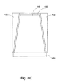
- FIG. 4C is a schematic illustration of a lens holder according to one embodiment of the present invention.
- FIG. 5 is a flow chart illustration of a method, according to one embodiment of the present invention.
- the terms “receiving unit” and “imaging unit” relate to any unit suitable for receiving, processing or further transmitting illumination rays remitted from a target or data derived from these rays.
- an imager or camera such as a Charge Coupled Device (CCD) camera or imager or a Complementary Metal Oxide Semiconductor (CMOS) imager or camera may be used; other suitable receiving or imaging units may be used.
- the term “receiving unit” may include an optical element suitable for receiving, processing or further transmitting illumination rays remitted from a target.
- An optical element may include for example, a lens.
- a system may include an in-vivo sensing device transmitting information (e.g., images and/or other data) to a data receiver and/or recorder possibly close to or worn on a subject.
- a data receiver and/or recorder may of course take other suitable configurations.
- the data receiver and/or recorder may transfer the received information to a larger computing device, such as a workstation or personal computer, where the data may be further analyzed, stored, and/or displayed to a user.
- a larger computing device such as a workstation or personal computer
- each of the various components need not be required and or may be housed in alternate configurations; for example, an internal device may transmit or otherwise transfer (e.g., by wire) information directly to a viewing or processing system.
- the data receiver or workstation may transmit or otherwise transfer information to the in-vivo device. While in one embodiment the device may be an autonomous capsule, other configurations, such as an endoscope or trocar may be used.
- embodiments of the present invention may be directed to an autonomous, typically ingestible in-vivo device. Other embodiments need not be ingestible.
- Devices or systems according to embodiments of the present invention may be similar to embodiments described in US application publication number 2001/0035902 published on 1 Nov. 2001 and/or in U.S. Pat. No. 5,604,531, each of which are assigned to the common assignee of the present invention and each of which are hereby fully incorporated herein by reference.
- a receiving and/or display system suitable for use with embodiments of the present invention may also be similar to embodiments described in US publication number 2001/0035902 and/or in U.S. Pat. No. 5,604,531.
- Devices and systems as described herein may have other configurations and other sets of components.
- FIG. 1 is a schematic diagram of a device and system according to one embodiment of the present invention.
- the system may include an in-vivo imaging device, such as for example a device 40 which may, for example, be capsule shaped and have a longitudinal axis L, an optical system 10 including, for example, optical dome or viewing window 54 , one or more lens(es) 49 , lens holder or separator 48 , an imager 46 , one or more illumination source(s) 42 and backscatter blockers 43 and 45 , also referred to herein as blocking elements, and one or more power source(s) 29 .
- an in-vivo imaging device such as for example a device 40 which may, for example, be capsule shaped and have a longitudinal axis L
- an optical system 10 including, for example, optical dome or viewing window 54 , one or more lens(es) 49 , lens holder or separator 48 , an imager 46 , one or more illumination source(s) 42 and backscatter blockers 43 and 45 , also
- Power source(s) 29 may be, for example, a suitable battery, but in further embodiments may be other devices, such as a unit for receiving power from an external source.
- Viewing window 54 typically dome shaped, may typically define a space 52 behind which are positioned components such as imager 46 , lens holder 48 , one or more lenses 49 , and one or more illumination source(s) 42 .
- Window 54 may be a protective optical window, preferably made of plastic such as thermoplastic polyurethane resins, polymethyl, methacrylate, cyclic olefin copolymer, polycarbonatesor other suitable plastic glass or ceramic transparent material.
- the imager 46 images via window 54 and illumination source(s) 42 illuminate via window 54 .
- Lens holder 48 may be concentric with the longitudinal axis L and may include an aperture through which light reflected from, for example, an object 15 may be received.
- Device 40 may include a transmitter 41 (typically operating wirelessly via radio waves), and an antenna 44 , for transmitting images and possibly other information to, for example, an external receiving device 12 .
- transmitter 41 typically operating wirelessly via radio waves
- antenna 44 for transmitting images and possibly other information to, for example, an external receiving device 12 .
- Other types of transmitters and transmission methods may be used; for example, in an endoscope application, wire or other transmission may be used.
- Device 40 may include a transceiver 51 that may be capable of receiving wireless signals and transmitting wireless signals; in some embodiments transceiver 51 may be a transmitter only and only transmission may occur. According to some embodiments transceiver 51 may be used instead of transmitter 41 . Transceiver 51 may also have other functions. In some embodiments, transceiver 51 and a processor 47 may be included in a single integrated circuit. In some embodiments, antenna 44 may be used for both the receipt and transmission of wireless signals by transceiver 51 . In other embodiments there may be more than one antenna. In some embodiments, device 40 may transmit but not receive signals.
- imager 46 may be fixed or otherwise attached to a substrate such as, for example, a circuit board 64 or directly positioned onto a substrate 56 .
- the various components of the device 40 may be disposed on a circuit board including rigid and flexible portions; preferably the components are arranged in a stacked vertical fashion.
- circuit board 64 may be further attached to a substrate 56 , which may for example support illumination source(s) 42 and which may define a viewing direction 60 of device 40 .
- Window 54 may form space 52 , so that illumination source(s) 42 , imager 46 , and/or lens holder 48 may be recessed behind window 54 .
- an imaging device may include more than one image sensor.
- an additional optical system may be included in a direction opposite viewing direction 60 , to form for example a double ended viewing device.
- Other configurations for including more than one imager 46 in device 40 and/or more than one viewing direction may be implemented.
- Device 40 and other devices disclosed herein, may be used to view lumens such as the gastrointestinal tract in a natural state and/or in an unmodified form, not using or requiring techniques such as insufflation.
- Image receiver 12 may include an image receiver storage unit 16 .
- Data processor 14 may include a processor and/or CPU 19 and a storage unit 21 .
- the window 54 may be, for example part of a housing 62 of the device 40 and may preferably be made of plastic, glass, ceramic or other transparent material. Typically, the in vivo area to be viewed may be illuminated and viewed through the window 54 , and thus components such as the imager 46 and illumination elements 42 may be behind the window 54 , within the device 40 .
- Main body or housing 62 may be in some embodiments the tube of an endoscope or trocar, and thus may extend further rearward than may be depicted in the device 40 of FIG. 1 .
- Imager 46 may include, for example, a CCD camera or imager, a CMOS camera or imager, a digital camera, a still camera, a video camera, or other suitable one or more imagers, cameras, receiving units or image acquisition components.
- Device 40 may typically be or may typically include an autonomous swallowable capsule, which may be self contained, but device 40 may have other shapes and need not be swallowable or autonomous (e.g., device 40 may have other configurations, such as that of an endoscope or trocar).
- Device 40 may be in the form of a capsule or other unit where all the components may be substantially contained within a container, housing, or shell, and where device 40 may not require any wires or cables to, for example, receive power or transmit information and may be autonomous.
- all of the components may be sealed within the device body (the body or shell may include more than one piece); for example, an imager, illumination units, power units, and transmitting and control units, may all be sealed within the device body.
- Device 40 may communicate with an external receiving and display system to provide display of data, control, or other functions.
- power may be provided by an internal battery or a wireless receiving system.
- Other embodiments may have other configurations and capabilities.
- components may be distributed over multiple sites or units. Control information may be received from an external source.
- Transmitter 41 may include control capability, for example controlling the various operations of device 40 , although control capability, or one or more aspects of control may be included in a separate component.
- transmitter 41 may typically be an ASIC (application specific integrated circuit), but may be of other constructions; for example, transmitter 41 may be a processor executing instructions.
- Device 40 may include a processing unit separate from transmitter 41 that may, for example, contain or process instructions.
- Image receiver 12 may typically include an antenna or antenna array and an image receiver storage unit 16 .
- Data processor 14 may include a processor 19 and a storage unit 21 .
- Image monitor 18 may display, inter alia, images recorded by, for example, device 40 .
- data processor 14 and monitor 18 may be part of a personal computer or workstation, which may include standard components such as a processor 19 , a memory, a disk drive, and input-output devices, although alternate configurations are possible.
- Data processor 14 may typically, as part of its functionality, act as a controller controlling the display of the images.
- Image monitor 18 may typically be a conventional video display, but may, in addition, be any other device capable of providing images or other data and may be of any size monitor including large projection size monitors.
- the image monitor 18 may present the image data, typically in the form of still and/or a stream of image frames, and in addition may present other information.
- the various categories of information may be displayed in windows. Other displaying formats may be used.
- one or more of the components included in receiver 12 and data processor and/or workstation 14 may be packaged in alternate configuration and may be or may be included in a portable or stationary device, package, and/or housing.
- imager 46 may capture images and may send data representing the images to transmitter 41 , which may transmit data to image receiver 12 using, for example, electromagnetic radio waves.
- Image receiver 12 may transfer the image data to image receiver storage unit 16 .
- the image data stored in storage unit 16 may be transferred to the data processor 14 or the data processor storage unit 21 .
- the image receiver 12 or image receiver storage unit 16 may be taken off the patient's body and may be connected to a personal computer or workstation that may include the data processor 14 via a standard data link, e.g., a serial, parallel, USB, or wireless interface.
- the image data may then be transferred from the image receiver storage unit 16 to data processor storage unit 21 .
- Data processor 14 may analyze the data and provide the analyzed data to the image monitor 18 , where a user views the image data.
- Other configurations allow for real time viewing. Further, other methods of recording, transmitting, storing and viewing images recorded by imager 46 may be used.
- FIG. 2A a schematic two dimensional presentation of an optical system according to an embodiment of the present invention.
- the optical system generally referenced as 10 may be included in, for example, device 40 of FIG. 1 , but may be included in other suitable devices, such as an endoscope, trocar, or other in-vivo imaging device.
- Optical system 10 may include, for example, illumination source(s) 42 , imager 46 , and one or more lenses 49 disposed and possibly recessed behind a window 54 , for viewing, for example, a target or object 15 .
- One, two, or more than two (for example three, four, six or eight) illumination sources may be used.
- the one or more lenses 49 may be positioned, for example, along longitudinal axis A of the in-vivo imaging device 40 .
- imager 46 a lens holder 48 and/or lens 49 may be positioned at any location within the optical system 10 , for example according to a manufacturer's instructions or a user such as a physician requirements, and employing different imaging devices with different optical design without the hindrance of backscatter interference.
- Light 256 may be emitted from an illumination source 42 for illuminating target 15 .
- a percent of the light (represented by ray 217 ) may be internally reflected from the window 54 internal surface 54 ′ and may be propagated to, for example, the lens 49 .
- a percent of the light 256 (represented by ray 258 ) may be incident on target 15 (e.g., an object or area in-vivo) and may be reflected or scattered from target 15 and received through aperture 48 ′ and/or lens 49 by imager 46 .
- a blocker such as a backscatter blocker 210
- a blocker may be positioned, for example, above lens 49 so that it will block light rays, such as 217 that are expected to be incident on point 270 on window 54 , from which point it is calculated that rays will be internally reflected and will reach the lens 49 .
- point 270 forms a geometrical point of reflection for a light ray incident on point 270 from illumination source 42 and reflected to the imager 46 (via aperture 48 ′ and lens 49 ), in the absence of backscatter blocker 210 .
- the illumination source(s) 42 may be extended illuminations source(s), that is, non pin point illumination source(s)
- the point of reflection 270 may be an area, or region, of reflection. In general, the term “area of reflection” will be understood to include the limiting case of “point of reflection”.
- the longitudinal axis A may be perpendicular to backscatter blocker 210 .
- the window 54 is a three dimensional structure.
- a schematic three dimensional representation of the optical system 10 of FIG. 2A is shown in FIG. 2B .
- the blocking and cutting off a percentage (e.g. rays 217 ) of the light 256 emitted from illumination source(s) 42 will reduce the light quantity in the vicinity of the window, such as in area 270 , but will still cause no dark or shadowed areas on the final image, because only a small percent of the light is being blocked from reaching point 270 and this lack of light is compensated by the other illumination sources.
- the illumination source(s) 42 may be extended illuminations source(s), that is non pin point illumination source(s), the dark and shadowed areas may be compensated by other light rays (e.g. light rays which are not blocked by the backscatter blocker 210 ) emitting from the illumination source(s) 42 .
- FIG. 3 showing a case in which a percent of the light (represented by ray 310 ) emitted from an illumination source 42 may be internally reflected from a housing 362 of device 40 to the window 54 internal surface 54 ′ and may be propagated to, for example, the lens 49 (represented by ray 310 ′), thus causing a back-reflection effect.
- a backscatter blocker like 380 , may be placed in close proximity to the illumination source 42 and block light, such as presented by light ray 310 , from reaching specific areas of the window 54 .
- the backscatter blocker 380 may also be placed in close proximity to the housing 362 of device 40 .
- Rays 310 and 310 ′ illustrate an example of light that would reach the lens 49 after two reflections (double reflection backscatter), if the backscatter blocker 380 were absent.
- double reflection backscatter can be eliminated by positioning the backscatter blocker 380 between the illumination source 42 and a first point of reflection from the internal surface 54 ′.
- Blocking reflecting light rays, such as light ray 310 ′, from reaching specific areas in an in-vivo imaging device such as the optical dome 54 or housing 362 of device 40 , will may not typically visibly affect the quantity or quality of light in the field of view (FOV) of an in-vivo imaging device such as the FOV 390 of device 40 .
- light ray 310 ′′ when not blocked by backscatter blocker 380 would have continued to illuminate an area outside FOV 390 .
- the longitudinal axis L may be substantially parallel to the backscatter blocker 380 .
- FIG. 4A showing an assembly 400 for positioning a backscatter blocker on and/or with respect to a lens holder and an illumination source, according to an embodiment of the present invention.
- terms like over, above, on, below, etc. are considered relative terms descriptive when a device is in a certain orientation relative to the viewer; it should be understood that these terms are relative, and given a certain orientation, an optical system may be “below” or “to the side of” an image sensor.
- lens holder 420 together with lens structure 430 may be positioned over imager 450 .
- a first backscatter blocker such as an upper backscatter blocker 425 may be placed on lens holder 420 and may be distal the imager 450
- a second backscatter blocker such as a lower backscatter blocker 470 may be positioned in the vicinity of illumination source(s) 460 and may be proximal the imager 450
- the lens holder 420 and the backscatter blocker 470 may be fixed and or secured with, for example, an adhesive 490 onto a substrate, such as a circuit board 480 , with for example, one or more protrusions or legs 471 and 471 ′ of backscatter blocker 470 and lens holder 420 .
- the lens holder 420 may incorporate protrusion 427 for assembling the upper backscatter blocker 425 onto and/or over lens holder 420 .
- protrusion(s) 427 may be adhered to the upper backscatter blocker 425 by, for example, gluing, friction fitting, press fitting, welding, laser welding, and/or other suitable methods.
- Other suitable surfaces, other than and/or in addition to protrusion 427 of lens holder 420 may be used to attach the upper backscatter blocker 425 to lens holder 420 .
- the upper backscatter blocker may be an integral part of lens holder 420 .
- an indentation or other cavity, etc. may be added to lens holder 420 and/or to the upper backscatter blocker 425 and the lower backscatter blocker, for example so that the upper backscatter blocker 425 and the lower backscatter blocker 470 may, for example, snap into place.
- the lower backscatter blocker with openings 473 may be manufactured and or fabricated, with a high degree of accuracy, as may be required, using well-known methods in the art, for example, etching and laser-cutting. Other suitable manufacturing processes may be used as well.
- the lower backscatter blocker may include one or more openings, for example four openings 473 for accommodating the illumination source and another opening, such as a square shaped opening 474 for placing the lens holder in the center of the backscatter blocker 470 .
- the backscatter blocker 470 may be made from any suitable plastic, e.g. ABS, and manufactured by, for example injection molding or other suitable methods. In some embodiments of the present invention, backscatter blocker 470 may be non- transparent so that light may not penetrate through the backscatter blocker 470 . Other suitable materials or methods may be used to manufacture backscatter blocker 470 .
- FIG. 4C showing a lens holder 430 positioned, for example over an imager 450 according to embodiments of the present invention.
- the lens holder 430 may incorporate a backscatter blocker 432 so that the backscatter blocker 432 and the lens holder 430 form a single integral unit.
- the lens holder which may include a backscatter blocker 432 may be fabricated by, for example, by single cavity injection molding.
- the lens holder may be manufactured by multi-cavity injection molding where, as a first step for example, an opaque material such as any of the materials mentioned herein which may include a suitable color, may be injected in a mold in, for example, an area of the surrounding wall of lens holder, and as a second step for example, a transparent material may be injected into for example the area in the mold of the lens holder.
- the steps may be of a different order or more steps may be added.
- backscatter blocker 432 may have an opaque section that isolates the imager and/or lens structure 449 from surrounding stray light and a transparent section that includes, for example, lens structure 449 .
- FIG. 5 A method for blocking stray light in an in-vivo imaging device according to some embodiment of the present invention is shown in FIG. 5 .
- the method may include providing an illumination source ( 500 ), providing one or more backscatter blockers ( 510 ) and positioning the backscatter blockers on a substrate and/or a component ( 520 ) of the imaging device, for example on a Printed Circuit Board (PCB) and/or a lens holder or an illumination source, so that the backscatter blockers will prevent rays from reaching an area on the viewing window from which light will be internally reflected onto the imager, causing undesired glare.
- PCB Printed Circuit Board
- the method may further include inserting the substrate and/or the component into a housing of an in-vivo device ( 530 ).
- the area on the viewing window from which light will be internally reflected is calculated by using computer programs, like LightTools or TracePro, that simulate a three dimensional optical unit and a realistically distributed in space and angles light source.
- calculations may be performed using the non-sequential method of Zemax, Code-V or OSLO programs.
Abstract
Description
Claims (5)
Priority Applications (3)
| Application Number | Priority Date | Filing Date | Title |
|---|---|---|---|
| US11/645,787 US9320417B2 (en) | 2005-12-29 | 2006-12-27 | In-vivo optical imaging device with backscatter blocking |
| PCT/IL2007/001553 WO2008078316A2 (en) | 2006-12-27 | 2007-12-16 | In-vivo imaging optical device |
| US15/071,248 US9615730B2 (en) | 2005-12-29 | 2016-03-16 | In-vivo imaging device with backscatter blocking |
Applications Claiming Priority (2)
| Application Number | Priority Date | Filing Date | Title |
|---|---|---|---|
| US11/319,769 US20070167834A1 (en) | 2005-12-29 | 2005-12-29 | In-vivo imaging optical device and method |
| US11/645,787 US9320417B2 (en) | 2005-12-29 | 2006-12-27 | In-vivo optical imaging device with backscatter blocking |
Related Parent Applications (1)
| Application Number | Title | Priority Date | Filing Date |
|---|---|---|---|
| US11/319,769 Continuation-In-Part US20070167834A1 (en) | 2005-12-29 | 2005-12-29 | In-vivo imaging optical device and method |
Related Child Applications (1)
| Application Number | Title | Priority Date | Filing Date |
|---|---|---|---|
| US15/071,248 Continuation US9615730B2 (en) | 2005-12-29 | 2016-03-16 | In-vivo imaging device with backscatter blocking |
Publications (2)
| Publication Number | Publication Date |
|---|---|
| US20070232852A1 US20070232852A1 (en) | 2007-10-04 |
| US9320417B2 true US9320417B2 (en) | 2016-04-26 |
Family
ID=39563034
Family Applications (2)
| Application Number | Title | Priority Date | Filing Date |
|---|---|---|---|
| US11/645,787 Expired - Fee Related US9320417B2 (en) | 2005-12-29 | 2006-12-27 | In-vivo optical imaging device with backscatter blocking |
| US15/071,248 Active US9615730B2 (en) | 2005-12-29 | 2016-03-16 | In-vivo imaging device with backscatter blocking |
Family Applications After (1)
| Application Number | Title | Priority Date | Filing Date |
|---|---|---|---|
| US15/071,248 Active US9615730B2 (en) | 2005-12-29 | 2016-03-16 | In-vivo imaging device with backscatter blocking |
Country Status (2)
| Country | Link |
|---|---|
| US (2) | US9320417B2 (en) |
| WO (1) | WO2008078316A2 (en) |
Cited By (1)
| Publication number | Priority date | Publication date | Assignee | Title |
|---|---|---|---|---|
| US9615730B2 (en) * | 2005-12-29 | 2017-04-11 | Given Imaging Ltd. | In-vivo imaging device with backscatter blocking |
Families Citing this family (6)
| Publication number | Priority date | Publication date | Assignee | Title |
|---|---|---|---|---|
| EP1399201B1 (en) * | 2001-01-11 | 2012-04-11 | Given Imaging Ltd. | Device for in-vivo procedures |
| US7662094B2 (en) | 2002-05-14 | 2010-02-16 | Given Imaging Ltd. | Optical head assembly with dome, and device for use thereof |
| US20070156051A1 (en) * | 2005-12-29 | 2007-07-05 | Amit Pascal | Device and method for in-vivo illumination |
| CN106510607B (en) * | 2016-12-07 | 2019-10-01 | 上海澳华光电内窥镜有限公司 | A kind of endoscope illumination optical system and fujinon electronic video endoscope |
| GB2574417B (en) * | 2018-06-05 | 2021-03-03 | Dyson Technology Ltd | A vision system for a mobile robot |
| EP4011270A1 (en) | 2020-12-08 | 2022-06-15 | Ambu A/S | Endoscope tip part with improved optical properties |
Citations (141)
| Publication number | Priority date | Publication date | Assignee | Title |
|---|---|---|---|---|
| US3683890A (en) | 1970-10-02 | 1972-08-15 | Charles B Beal | Carrier system for delivery of an end of an elongated member to the upper gastrointestinal tract |
| US3971362A (en) | 1972-10-27 | 1976-07-27 | The United States Of America As Represented By The Administrator Of The National Aeronautics And Space Administration | Miniature ingestible telemeter devices to measure deep-body temperature |
| US4178735A (en) | 1977-07-13 | 1979-12-18 | The Kendall Company | Method of sheathing catheter |
| DE2929429A1 (en) | 1978-07-27 | 1980-02-07 | Olympus Optical Co | CAMERA SYSTEM |
| US4239040A (en) | 1976-10-19 | 1980-12-16 | Kabushiki Kaisha Daini Seikosha | Capsule for medical use |
| US4262632A (en) | 1974-01-03 | 1981-04-21 | Hanton John P | Electronic livestock identification system |
| US4439197A (en) | 1981-03-23 | 1984-03-27 | Olympus Optical Co., Ltd. | Medical capsule device |
| DE3440177A1 (en) | 1984-11-02 | 1986-05-15 | Friedrich Dipl.-Ing. 8031 Eichenau Hilliges | Television recording and replay device for endoscopy on human and animal bodies |
| US4646724A (en) | 1982-10-15 | 1987-03-03 | Olympus Optical Co., Ltd. | Endoscopic photographing apparatus |
| US4689621A (en) | 1986-03-31 | 1987-08-25 | The United States Of America As Represented By The Administrator Of The National Aeronautics And Space Administration | Temperature responsive transmitter |
| US4803992A (en) | 1980-10-28 | 1989-02-14 | Lemelson Jerome H | Electro-optical instruments and methods for producing same |
| US4819620A (en) | 1986-08-16 | 1989-04-11 | Ichiro Okutsu | Endoscope guide pipe |
| US4844076A (en) | 1988-08-26 | 1989-07-04 | The Johns Hopkins University | Ingestible size continuously transmitting temperature monitoring pill |
| US4936823A (en) | 1988-05-04 | 1990-06-26 | Triangle Research And Development Corp. | Transendoscopic implant capsule |
| US4940997A (en) | 1989-08-08 | 1990-07-10 | Hewlett-Packard Company | Out-of-ink sensing method |
| US5042486A (en) | 1989-09-29 | 1991-08-27 | Siemens Aktiengesellschaft | Catheter locatable with non-ionizing field and method for locating same |
| US5081041A (en) | 1990-04-03 | 1992-01-14 | Minnesota Mining And Manufacturing Company | Ionic component sensor and method for making and using same |
| US5109870A (en) | 1988-10-25 | 1992-05-05 | Forschungsgesellschaft Fur Biomedizinische Technik E.V. | Apparatus for and method of motility and peristalsis monitoring |
| US5187572A (en) | 1990-10-31 | 1993-02-16 | Olympus Optical Co., Ltd. | Endoscope system with a plurality of synchronized light source apparatuses |
| US5193525A (en) * | 1990-11-30 | 1993-03-16 | Vision Sciences | Antiglare tip in a sheath for an endoscope |
| US5211165A (en) | 1991-09-03 | 1993-05-18 | General Electric Company | Tracking system to follow the position and orientation of a device with radiofrequency field gradients |
| FR2688997A1 (en) | 1992-03-26 | 1993-10-01 | Lambert Alain | Autonomous telemetric capsule for exploring small bowel - contains sampler for carrying out mucous biopsies, radio transmitter and position detector |
| US5267033A (en) | 1990-11-28 | 1993-11-30 | Dai Nippon Printing Co., Ltd. | Hollow body inspection system, hollow body inspection apparatus and signal transmission apparatus |
| US5279607A (en) | 1991-05-30 | 1994-01-18 | The State University Of New York | Telemetry capsule and process |
| US5330427A (en) | 1991-07-02 | 1994-07-19 | Ortho Pharmaceutical Corporation | Prefilled suppository applicator |
| US5368027A (en) | 1992-04-23 | 1994-11-29 | Avl Medical Instruments Ag | Sensor arrangement for direct or indirect optical determination of physical or chemical properties |
| US5395366A (en) | 1991-05-30 | 1995-03-07 | The State University Of New York | Sampling capsule and process |
| US5398670A (en) | 1993-08-31 | 1995-03-21 | Ethicon, Inc. | Lumen traversing device |
| US5429132A (en) | 1990-08-24 | 1995-07-04 | Imperial College Of Science Technology And Medicine | Probe system |
| US5479935A (en) | 1993-10-21 | 1996-01-02 | Synectics Medical, Inc. | Ambulatory reflux monitoring system |
| US5490969A (en) | 1994-06-30 | 1996-02-13 | General Electric Company | Mould for isostatic pressing |
| US5495114A (en) | 1992-09-30 | 1996-02-27 | Adair; Edwin L. | Miniaturized electronic imaging chip |
| US5549109A (en) | 1993-10-01 | 1996-08-27 | Target Therapeutics, Inc. | Sheathed multipolar catheter and multipolar guidewire for sensing cardiac electrical activity |
| US5558640A (en) | 1994-03-17 | 1996-09-24 | Siemens Aktiengesellschaft | System for infusion of medicine into the body of a patient |
| US5604531A (en) | 1994-01-17 | 1997-02-18 | State Of Israel, Ministry Of Defense, Armament Development Authority | In vivo video camera system |
| US5697384A (en) | 1993-03-26 | 1997-12-16 | Surge Miyawaki Co., Ltd. | Internal identification apparatus for animals |
| US5800350A (en) | 1993-11-01 | 1998-09-01 | Polartechnics, Limited | Apparatus for tissue type recognition |
| US5819736A (en) | 1994-03-24 | 1998-10-13 | Sightline Technologies Ltd. | Viewing method and apparatus particularly useful for viewing the interior of the large intestine |
| US5837196A (en) | 1996-01-26 | 1998-11-17 | The Regents Of The University Of California | High density array fabrication and readout method for a fiber optic biosensor |
| US5892630A (en) | 1992-02-10 | 1999-04-06 | Linvatec Corporation | Disposable endoscope |
| US5913820A (en) | 1992-08-14 | 1999-06-22 | British Telecommunications Public Limited Company | Position location system |
| US5929901A (en) | 1997-10-06 | 1999-07-27 | Adair; Edwin L. | Reduced area imaging devices incorporated within surgical instruments |
| WO1999032028A3 (en) | 1997-12-22 | 1999-09-10 | Given Imaging Ltd | System and method for in vivo delivery of autonomous capsule |
| US5986693A (en) | 1997-10-06 | 1999-11-16 | Adair; Edwin L. | Reduced area imaging devices incorporated within surgical instruments |
| US5993378A (en) | 1980-10-28 | 1999-11-30 | Lemelson; Jerome H. | Electro-optical instruments and methods for treating disease |
| US6043839A (en) | 1997-10-06 | 2000-03-28 | Adair; Edwin L. | Reduced area imaging devices |
| US6095970A (en) | 1997-02-19 | 2000-08-01 | Asahi Kogaku Kogyo Kabushiki Kaisha | Endoscope |
| US6099482A (en) | 1997-08-22 | 2000-08-08 | Innotek Pet Products, Inc. | Ingestible animal temperature sensor |
| US6149581A (en) | 1997-06-12 | 2000-11-21 | Klingenstein; Ralph James | Device and method for access to the colon and small bowel of a patient |
| JP2000342522A (en) | 1999-06-07 | 2000-12-12 | Asahi Optical Co Ltd | Swallow type endoscopic device |
| JP2000342525A (en) | 1999-06-07 | 2000-12-12 | Asahi Optical Co Ltd | Swallow type endoscopic device |
| JP2000342524A (en) | 1999-06-07 | 2000-12-12 | Asahi Optical Co Ltd | Swallow type endoscopic device |
| WO2000076391A1 (en) | 1999-06-15 | 2000-12-21 | Given Imaging Ltd. | An optical system |
| US6174291B1 (en) | 1998-03-09 | 2001-01-16 | Spectrascience, Inc. | Optical biopsy system and methods for tissue diagnosis |
| WO2001008548A1 (en) | 1999-08-03 | 2001-02-08 | The University College London Hospitals Nhs Trust | Improved passage-travelling device |
| WO2001010291A1 (en) | 1999-08-04 | 2001-02-15 | Given Imaging Ltd. | A method for temperature sensing |
| JP2001091860A (en) | 1999-09-22 | 2001-04-06 | Asahi Optical Co Ltd | Capsule endoscope |
| JP2001095755A (en) | 1999-09-30 | 2001-04-10 | Asahi Optical Co Ltd | Capsule type endoscope |
| JP2001095756A (en) | 1999-09-30 | 2001-04-10 | Asahi Optical Co Ltd | Capsule type endoscope |
| JP2001104241A (en) | 1999-10-04 | 2001-04-17 | Asahi Optical Co Ltd | Capsule endoscope |
| JP2001104287A (en) | 1999-10-04 | 2001-04-17 | Asahi Optical Co Ltd | Capsule endoscope |
| JP2001104242A (en) | 1999-10-04 | 2001-04-17 | Asahi Optical Co Ltd | Capsule endoscope |
| JP2001104243A (en) | 1999-10-04 | 2001-04-17 | Asahi Optical Co Ltd | Capsule endoscope |
| JP2001104244A (en) | 1999-10-04 | 2001-04-17 | Asahi Optical Co Ltd | Capsule endoscope |
| JP2001112740A (en) | 1999-10-20 | 2001-04-24 | Asahi Optical Co Ltd | Capsulated endoscope |
| JP2001112709A (en) | 1999-10-20 | 2001-04-24 | Asahi Optical Co Ltd | Capsulated endscope |
| JP2001112710A (en) | 1999-10-20 | 2001-04-24 | Asahi Optical Co Ltd | Capsulated endoscope |
| US6228048B1 (en) | 1998-10-23 | 2001-05-08 | Cm Robbins Company Inc. | Colonic irrigation apparatus and method |
| US6233476B1 (en) | 1999-05-18 | 2001-05-15 | Mediguide Ltd. | Medical positioning system |
| JP2001137182A (en) | 1999-11-10 | 2001-05-22 | Olympus Optical Co Ltd | Capsule endoscope for medical use |
| US6240312B1 (en) | 1997-10-23 | 2001-05-29 | Robert R. Alfano | Remote-controllable, micro-scale device for use in in vivo medical diagnosis and/or treatment |
| JP2001224553A (en) | 2000-02-17 | 2001-08-21 | Asahi Optical Co Ltd | Imaging instrument for capusle endoscope |
| JP2001224551A (en) | 2000-02-15 | 2001-08-21 | Asahi Optical Co Ltd | Capsule endoscope |
| JP2001231744A (en) | 2000-02-21 | 2001-08-28 | Asahi Optical Co Ltd | Capsule endoscope |
| US20010017649A1 (en) | 1999-02-25 | 2001-08-30 | Avi Yaron | Capsule |
| US6285897B1 (en) | 1999-04-07 | 2001-09-04 | Endonetics, Inc. | Remote physiological monitoring system |
| JP2001245844A (en) | 2000-03-03 | 2001-09-11 | Asahi Optical Co Ltd | Capsule endoscope |
| WO2001069212A1 (en) | 2000-03-14 | 2001-09-20 | Given Imaging Ltd. | Device and method for in vitro detection of blood |
| US20010025135A1 (en) | 2000-03-21 | 2001-09-27 | Olympus Optical Co., Ltd. | Endoscope |
| US20010035902A1 (en) | 2000-03-08 | 2001-11-01 | Iddan Gavriel J. | Device and system for in vivo imaging |
| US6324418B1 (en) | 1997-09-29 | 2001-11-27 | Boston Scientific Corporation | Portable tissue spectroscopy apparatus and method |
| WO2001050941A3 (en) | 2000-01-13 | 2001-12-06 | Moshe Refael | Encapsulated medical imaging device and method |
| US20010051766A1 (en) | 1999-03-01 | 2001-12-13 | Gazdzinski Robert F. | Endoscopic smart probe and method |
| JP2002010990A (en) | 2000-05-31 | 2002-01-15 | Given Imaging Ltd | Measurement of electric characteristics of tissue |
| US20020015952A1 (en) | 1999-07-30 | 2002-02-07 | Anderson Norman G. | Microarrays and their manufacture by slicing |
| US6369812B1 (en) | 1997-11-26 | 2002-04-09 | Philips Medical Systems, (Cleveland), Inc. | Inter-active viewing system for generating virtual endoscopy studies of medical diagnostic data with a continuous sequence of spherical panoramic views and viewing the studies over networks |
| US6395562B1 (en) | 1998-04-22 | 2002-05-28 | The Regents Of The University Of California | Diagnostic microarray apparatus |
| US6428470B1 (en) | 1995-09-15 | 2002-08-06 | Pinotage, Llc | Imaging system and components thereof |
| US20020146368A1 (en) | 2000-01-19 | 2002-10-10 | Gavriel Meron | System and method for determining the presence of a substance in-vivo |
| US20020158976A1 (en) | 2001-03-29 | 2002-10-31 | Vni Dov A. | Method for timing control |
| US6475145B1 (en) | 2000-05-17 | 2002-11-05 | Baymar, Inc. | Method and apparatus for detection of acid reflux |
| US20020173718A1 (en) | 2001-05-20 | 2002-11-21 | Mordechai Frisch | Array system and method for locating an in vivo signal source |
| US20020177779A1 (en) | 2001-03-14 | 2002-11-28 | Doron Adler | Method and system for detecting colorimetric abnormalities in vivo |
| US6488694B1 (en) | 1991-01-28 | 2002-12-03 | Advanced Cardiovascular Systems, Inc. | Stent delivery system |
| EP1263055A2 (en) | 2001-05-31 | 2002-12-04 | Konica Corporation | CMOS image sensor |
| WO2002055984A3 (en) | 2001-01-16 | 2003-01-03 | Given Imaging Ltd | A system and method for determining in vivo body lumen conditions |
| WO2002054932A3 (en) | 2001-01-16 | 2003-01-09 | Given Imaging Ltd | System and method for wide field imaging of body lumens |
| US20030018280A1 (en) | 2001-05-20 | 2003-01-23 | Shlomo Lewkowicz | Floatable in vivo sensing device and method for use |
| US20030023150A1 (en) | 2001-07-30 | 2003-01-30 | Olympus Optical Co., Ltd. | Capsule-type medical device and medical system |
| US20030020810A1 (en) | 2001-07-30 | 2003-01-30 | Olympus Optical Co., Ltd. | Capsule-type medical apparatus |
| US20030028078A1 (en) | 2001-08-02 | 2003-02-06 | Arkady Glukhovsky | In vivo imaging device, system and method |
| US20030045790A1 (en) | 2001-09-05 | 2003-03-06 | Shlomo Lewkowicz | System and method for three dimensional display of body lumens |
| US20030114742A1 (en) | 2001-09-24 | 2003-06-19 | Shlomo Lewkowicz | System and method for controlling a device in vivo |
| US20030130562A1 (en) | 2002-01-09 | 2003-07-10 | Scimed Life Systems, Inc. | Imaging device and related methods |
| US20030167000A1 (en) | 2000-02-08 | 2003-09-04 | Tarun Mullick | Miniature ingestible capsule |
| US20030171648A1 (en) | 2002-03-08 | 2003-09-11 | Takeshi Yokoi | Capsule endoscope |
| US20030171652A1 (en) | 2002-03-08 | 2003-09-11 | Takeshi Yokoi | Capsule endoscope |
| US20030171649A1 (en) | 2002-03-08 | 2003-09-11 | Takeshi Yokoi | Capsule endoscope |
| JP2003275171A (en) | 2002-01-18 | 2003-09-30 | Olympus Optical Co Ltd | Capsule endoscope |
| US6632175B1 (en) | 2000-11-08 | 2003-10-14 | Hewlett-Packard Development Company, L.P. | Swallowable data recorder capsule medical device |
| US20030195415A1 (en) | 2002-02-14 | 2003-10-16 | Iddan Gavriel J. | Device, system and method for accoustic in-vivo measuring |
| US20030214580A1 (en) | 2002-02-11 | 2003-11-20 | Iddan Gavriel J. | Self propelled device having a magnetohydrodynamic propulsion system |
| US20030214579A1 (en) | 2002-02-11 | 2003-11-20 | Iddan Gavriel J. | Self propelled device |
| US20030216622A1 (en) | 2002-04-25 | 2003-11-20 | Gavriel Meron | Device and method for orienting a device in vivo |
| US20030227547A1 (en) * | 2002-05-14 | 2003-12-11 | Iddan Gavriel J. | Optical head assembly with dome, and device for use thereof |
| US20040027459A1 (en) | 2002-08-06 | 2004-02-12 | Olympus Optical Co., Ltd. | Assembling method of capsule medical apparatus and capsule medical apparatus |
| US6692430B2 (en) | 2000-04-10 | 2004-02-17 | C2Cure Inc. | Intra vascular imaging apparatus |
| WO2003003706A3 (en) | 2001-06-28 | 2004-03-04 | Given Imaging Ltd | In vivo imaging device with a small cross sectional area |
| WO2003011103A3 (en) | 2001-08-02 | 2004-03-18 | Given Imaging Ltd | Apparatus and methods for in vivo imaging |
| WO2002094337A3 (en) | 2001-05-20 | 2004-03-18 | Given Imaging Ltd | A method for in vivo imaging of an unmodified gastrointestinal tract |
| JP2004121843A (en) | 2002-09-30 | 2004-04-22 | Given Imaging Ltd | System including optical head assembly, and dome, and in vivo imaging device |
| WO2004035106A2 (en) | 2002-10-21 | 2004-04-29 | Given Imaging Ltd. | Intubation and imaging device and system |
| JP2004129948A (en) | 2002-10-11 | 2004-04-30 | Olympus Corp | Capsule endoscope |
| WO2004028336A3 (en) | 2002-09-30 | 2004-05-21 | Given Imaging Ltd | Reduced size imaging device |
| WO2004045395A3 (en) | 2002-11-19 | 2004-07-08 | Given Imaging Ltd | System and method for stress and pressure sensing in an in-vivo device |
| US20040254455A1 (en) | 2002-05-15 | 2004-12-16 | Iddan Gavriel J. | Magneic switch for use in a system that includes an in-vivo device, and method of use thereof |
| US20050124858A1 (en) | 2003-09-01 | 2005-06-09 | Hirohiko Matsuzawa | Capsule type endoscope |
| WO2005053517A1 (en) | 2003-12-01 | 2005-06-16 | Olympus Corporation | Endoscope system |
| JP2005193053A (en) | 2003-12-30 | 2005-07-21 | Given Imaging Ltd | Lens structure assembly constituted to be positioned on image sensor, image sensor of in- vivo device and method for centering optical system on image sensor |
| US20050259098A1 (en) | 2004-05-21 | 2005-11-24 | Silicon Light Machines Corporation | Optical positioning device using telecentric imaging |
| US20060264709A1 (en) * | 2004-01-26 | 2006-11-23 | Olympus Corporation | Capsule-type medical apparatus |
| US20060287580A1 (en) * | 2005-06-17 | 2006-12-21 | Magnachip Semiconductor Ltd. | Capsule type endoscope and method for fabricating the same |
| IL126727A (en) | 1998-10-22 | 2006-12-31 | Given Imaging Ltd | Method for delivering a device to a target location |
| US7170677B1 (en) | 2002-01-25 | 2007-01-30 | Everest Vit | Stereo-measurement borescope with 3-D viewing |
| US20070191683A1 (en) * | 2005-04-12 | 2007-08-16 | Olympus Medical Systems Corp. | Body-insertable apparatus, in-vivo information acquiring system, and body-insertable apparatus manufacturing method |
| US7347817B2 (en) * | 2001-08-02 | 2008-03-25 | Given Imaging Ltd. | Polarized in vivo imaging device, system and method |
| JP4109927B2 (en) | 2002-08-20 | 2008-07-02 | セイコークロック株式会社 | Radio correction watch and method |
| JP4144533B2 (en) | 2004-02-24 | 2008-09-03 | ソニー株式会社 | Playback apparatus and method |
| JP5015515B2 (en) | 2006-08-02 | 2012-08-29 | 伊藤超短波株式会社 | Muscle training equipment |
| JP5745833B2 (en) | 2009-12-22 | 2015-07-08 | ゼロックス コーポレイションXerox Corporation | Sulfonamide-containing photoconductor |
| JP7111985B2 (en) | 2019-03-13 | 2022-08-03 | サミー株式会社 | game machine |
Family Cites Families (2)
| Publication number | Priority date | Publication date | Assignee | Title |
|---|---|---|---|---|
| US9320417B2 (en) * | 2005-12-29 | 2016-04-26 | Given Imaging Ltd. | In-vivo optical imaging device with backscatter blocking |
| US8262566B2 (en) * | 2008-07-14 | 2012-09-11 | Given Imaging Ltd. | Device and method for uniform in vivo illumination |
-
2006
- 2006-12-27 US US11/645,787 patent/US9320417B2/en not_active Expired - Fee Related
-
2007
- 2007-12-16 WO PCT/IL2007/001553 patent/WO2008078316A2/en active Application Filing
-
2016
- 2016-03-16 US US15/071,248 patent/US9615730B2/en active Active
Patent Citations (149)
| Publication number | Priority date | Publication date | Assignee | Title |
|---|---|---|---|---|
| US3683890A (en) | 1970-10-02 | 1972-08-15 | Charles B Beal | Carrier system for delivery of an end of an elongated member to the upper gastrointestinal tract |
| US3971362A (en) | 1972-10-27 | 1976-07-27 | The United States Of America As Represented By The Administrator Of The National Aeronautics And Space Administration | Miniature ingestible telemeter devices to measure deep-body temperature |
| US4262632A (en) | 1974-01-03 | 1981-04-21 | Hanton John P | Electronic livestock identification system |
| US4239040A (en) | 1976-10-19 | 1980-12-16 | Kabushiki Kaisha Daini Seikosha | Capsule for medical use |
| US4178735A (en) | 1977-07-13 | 1979-12-18 | The Kendall Company | Method of sheathing catheter |
| US4278077A (en) | 1978-07-27 | 1981-07-14 | Olympus Optical Co., Ltd. | Medical camera system |
| DE2929429A1 (en) | 1978-07-27 | 1980-02-07 | Olympus Optical Co | CAMERA SYSTEM |
| US4803992A (en) | 1980-10-28 | 1989-02-14 | Lemelson Jerome H | Electro-optical instruments and methods for producing same |
| US5993378A (en) | 1980-10-28 | 1999-11-30 | Lemelson; Jerome H. | Electro-optical instruments and methods for treating disease |
| US4439197A (en) | 1981-03-23 | 1984-03-27 | Olympus Optical Co., Ltd. | Medical capsule device |
| US4646724A (en) | 1982-10-15 | 1987-03-03 | Olympus Optical Co., Ltd. | Endoscopic photographing apparatus |
| DE3440177A1 (en) | 1984-11-02 | 1986-05-15 | Friedrich Dipl.-Ing. 8031 Eichenau Hilliges | Television recording and replay device for endoscopy on human and animal bodies |
| US4689621A (en) | 1986-03-31 | 1987-08-25 | The United States Of America As Represented By The Administrator Of The National Aeronautics And Space Administration | Temperature responsive transmitter |
| US4819620A (en) | 1986-08-16 | 1989-04-11 | Ichiro Okutsu | Endoscope guide pipe |
| US4936823A (en) | 1988-05-04 | 1990-06-26 | Triangle Research And Development Corp. | Transendoscopic implant capsule |
| US4844076A (en) | 1988-08-26 | 1989-07-04 | The Johns Hopkins University | Ingestible size continuously transmitting temperature monitoring pill |
| US5109870A (en) | 1988-10-25 | 1992-05-05 | Forschungsgesellschaft Fur Biomedizinische Technik E.V. | Apparatus for and method of motility and peristalsis monitoring |
| US4940997A (en) | 1989-08-08 | 1990-07-10 | Hewlett-Packard Company | Out-of-ink sensing method |
| US5042486A (en) | 1989-09-29 | 1991-08-27 | Siemens Aktiengesellschaft | Catheter locatable with non-ionizing field and method for locating same |
| US5081041A (en) | 1990-04-03 | 1992-01-14 | Minnesota Mining And Manufacturing Company | Ionic component sensor and method for making and using same |
| US5429132A (en) | 1990-08-24 | 1995-07-04 | Imperial College Of Science Technology And Medicine | Probe system |
| US5187572A (en) | 1990-10-31 | 1993-02-16 | Olympus Optical Co., Ltd. | Endoscope system with a plurality of synchronized light source apparatuses |
| US5267033A (en) | 1990-11-28 | 1993-11-30 | Dai Nippon Printing Co., Ltd. | Hollow body inspection system, hollow body inspection apparatus and signal transmission apparatus |
| US5193525A (en) * | 1990-11-30 | 1993-03-16 | Vision Sciences | Antiglare tip in a sheath for an endoscope |
| US6488694B1 (en) | 1991-01-28 | 2002-12-03 | Advanced Cardiovascular Systems, Inc. | Stent delivery system |
| US5279607A (en) | 1991-05-30 | 1994-01-18 | The State University Of New York | Telemetry capsule and process |
| US5395366A (en) | 1991-05-30 | 1995-03-07 | The State University Of New York | Sampling capsule and process |
| US5330427A (en) | 1991-07-02 | 1994-07-19 | Ortho Pharmaceutical Corporation | Prefilled suppository applicator |
| US5211165A (en) | 1991-09-03 | 1993-05-18 | General Electric Company | Tracking system to follow the position and orientation of a device with radiofrequency field gradients |
| US5892630A (en) | 1992-02-10 | 1999-04-06 | Linvatec Corporation | Disposable endoscope |
| FR2688997A1 (en) | 1992-03-26 | 1993-10-01 | Lambert Alain | Autonomous telemetric capsule for exploring small bowel - contains sampler for carrying out mucous biopsies, radio transmitter and position detector |
| US5368027A (en) | 1992-04-23 | 1994-11-29 | Avl Medical Instruments Ag | Sensor arrangement for direct or indirect optical determination of physical or chemical properties |
| US5913820A (en) | 1992-08-14 | 1999-06-22 | British Telecommunications Public Limited Company | Position location system |
| US5495114A (en) | 1992-09-30 | 1996-02-27 | Adair; Edwin L. | Miniaturized electronic imaging chip |
| US5697384A (en) | 1993-03-26 | 1997-12-16 | Surge Miyawaki Co., Ltd. | Internal identification apparatus for animals |
| US5398670A (en) | 1993-08-31 | 1995-03-21 | Ethicon, Inc. | Lumen traversing device |
| US5549109A (en) | 1993-10-01 | 1996-08-27 | Target Therapeutics, Inc. | Sheathed multipolar catheter and multipolar guidewire for sensing cardiac electrical activity |
| US5479935A (en) | 1993-10-21 | 1996-01-02 | Synectics Medical, Inc. | Ambulatory reflux monitoring system |
| US5800350A (en) | 1993-11-01 | 1998-09-01 | Polartechnics, Limited | Apparatus for tissue type recognition |
| US5604531A (en) | 1994-01-17 | 1997-02-18 | State Of Israel, Ministry Of Defense, Armament Development Authority | In vivo video camera system |
| US5558640A (en) | 1994-03-17 | 1996-09-24 | Siemens Aktiengesellschaft | System for infusion of medicine into the body of a patient |
| US5819736A (en) | 1994-03-24 | 1998-10-13 | Sightline Technologies Ltd. | Viewing method and apparatus particularly useful for viewing the interior of the large intestine |
| US5490969A (en) | 1994-06-30 | 1996-02-13 | General Electric Company | Mould for isostatic pressing |
| US6428470B1 (en) | 1995-09-15 | 2002-08-06 | Pinotage, Llc | Imaging system and components thereof |
| US5837196A (en) | 1996-01-26 | 1998-11-17 | The Regents Of The University Of California | High density array fabrication and readout method for a fiber optic biosensor |
| US6095970A (en) | 1997-02-19 | 2000-08-01 | Asahi Kogaku Kogyo Kabushiki Kaisha | Endoscope |
| US6149581A (en) | 1997-06-12 | 2000-11-21 | Klingenstein; Ralph James | Device and method for access to the colon and small bowel of a patient |
| US6099482A (en) | 1997-08-22 | 2000-08-08 | Innotek Pet Products, Inc. | Ingestible animal temperature sensor |
| US6324418B1 (en) | 1997-09-29 | 2001-11-27 | Boston Scientific Corporation | Portable tissue spectroscopy apparatus and method |
| US5986693A (en) | 1997-10-06 | 1999-11-16 | Adair; Edwin L. | Reduced area imaging devices incorporated within surgical instruments |
| US6043839A (en) | 1997-10-06 | 2000-03-28 | Adair; Edwin L. | Reduced area imaging devices |
| US5929901A (en) | 1997-10-06 | 1999-07-27 | Adair; Edwin L. | Reduced area imaging devices incorporated within surgical instruments |
| US6240312B1 (en) | 1997-10-23 | 2001-05-29 | Robert R. Alfano | Remote-controllable, micro-scale device for use in in vivo medical diagnosis and/or treatment |
| US6369812B1 (en) | 1997-11-26 | 2002-04-09 | Philips Medical Systems, (Cleveland), Inc. | Inter-active viewing system for generating virtual endoscopy studies of medical diagnostic data with a continuous sequence of spherical panoramic views and viewing the studies over networks |
| WO1999032028A3 (en) | 1997-12-22 | 1999-09-10 | Given Imaging Ltd | System and method for in vivo delivery of autonomous capsule |
| US6174291B1 (en) | 1998-03-09 | 2001-01-16 | Spectrascience, Inc. | Optical biopsy system and methods for tissue diagnosis |
| US6395562B1 (en) | 1998-04-22 | 2002-05-28 | The Regents Of The University Of California | Diagnostic microarray apparatus |
| IL126727A (en) | 1998-10-22 | 2006-12-31 | Given Imaging Ltd | Method for delivering a device to a target location |
| US6228048B1 (en) | 1998-10-23 | 2001-05-08 | Cm Robbins Company Inc. | Colonic irrigation apparatus and method |
| US20010017649A1 (en) | 1999-02-25 | 2001-08-30 | Avi Yaron | Capsule |
| US20020103417A1 (en) | 1999-03-01 | 2002-08-01 | Gazdzinski Robert F. | Endoscopic smart probe and method |
| US20010051766A1 (en) | 1999-03-01 | 2001-12-13 | Gazdzinski Robert F. | Endoscopic smart probe and method |
| US6285897B1 (en) | 1999-04-07 | 2001-09-04 | Endonetics, Inc. | Remote physiological monitoring system |
| US6233476B1 (en) | 1999-05-18 | 2001-05-15 | Mediguide Ltd. | Medical positioning system |
| JP2000342522A (en) | 1999-06-07 | 2000-12-12 | Asahi Optical Co Ltd | Swallow type endoscopic device |
| JP2000342524A (en) | 1999-06-07 | 2000-12-12 | Asahi Optical Co Ltd | Swallow type endoscopic device |
| JP2000342525A (en) | 1999-06-07 | 2000-12-12 | Asahi Optical Co Ltd | Swallow type endoscopic device |
| WO2000076391A1 (en) | 1999-06-15 | 2000-12-21 | Given Imaging Ltd. | An optical system |
| US6836377B1 (en) | 1999-06-15 | 2004-12-28 | Given Imaging Ltd. | Optical system |
| US20020015952A1 (en) | 1999-07-30 | 2002-02-07 | Anderson Norman G. | Microarrays and their manufacture by slicing |
| WO2001008548A1 (en) | 1999-08-03 | 2001-02-08 | The University College London Hospitals Nhs Trust | Improved passage-travelling device |
| WO2001010291A1 (en) | 1999-08-04 | 2001-02-15 | Given Imaging Ltd. | A method for temperature sensing |
| JP2001091860A (en) | 1999-09-22 | 2001-04-06 | Asahi Optical Co Ltd | Capsule endoscope |
| JP2001095756A (en) | 1999-09-30 | 2001-04-10 | Asahi Optical Co Ltd | Capsule type endoscope |
| JP2001095755A (en) | 1999-09-30 | 2001-04-10 | Asahi Optical Co Ltd | Capsule type endoscope |
| JP2001104242A (en) | 1999-10-04 | 2001-04-17 | Asahi Optical Co Ltd | Capsule endoscope |
| JP2001104241A (en) | 1999-10-04 | 2001-04-17 | Asahi Optical Co Ltd | Capsule endoscope |
| JP2001104244A (en) | 1999-10-04 | 2001-04-17 | Asahi Optical Co Ltd | Capsule endoscope |
| JP2001104287A (en) | 1999-10-04 | 2001-04-17 | Asahi Optical Co Ltd | Capsule endoscope |
| JP2001104243A (en) | 1999-10-04 | 2001-04-17 | Asahi Optical Co Ltd | Capsule endoscope |
| JP2001112710A (en) | 1999-10-20 | 2001-04-24 | Asahi Optical Co Ltd | Capsulated endoscope |
| JP2001112709A (en) | 1999-10-20 | 2001-04-24 | Asahi Optical Co Ltd | Capsulated endscope |
| JP2001112740A (en) | 1999-10-20 | 2001-04-24 | Asahi Optical Co Ltd | Capsulated endoscope |
| JP2001137182A (en) | 1999-11-10 | 2001-05-22 | Olympus Optical Co Ltd | Capsule endoscope for medical use |
| US20030208107A1 (en) | 2000-01-13 | 2003-11-06 | Moshe Refael | Encapsulated medical imaging device and method |
| WO2001050941A3 (en) | 2000-01-13 | 2001-12-06 | Moshe Refael | Encapsulated medical imaging device and method |
| US20020146368A1 (en) | 2000-01-19 | 2002-10-10 | Gavriel Meron | System and method for determining the presence of a substance in-vivo |
| US20030167000A1 (en) | 2000-02-08 | 2003-09-04 | Tarun Mullick | Miniature ingestible capsule |
| JP2001224551A (en) | 2000-02-15 | 2001-08-21 | Asahi Optical Co Ltd | Capsule endoscope |
| JP2001224553A (en) | 2000-02-17 | 2001-08-21 | Asahi Optical Co Ltd | Imaging instrument for capusle endoscope |
| JP2001231744A (en) | 2000-02-21 | 2001-08-28 | Asahi Optical Co Ltd | Capsule endoscope |
| JP2001245844A (en) | 2000-03-03 | 2001-09-11 | Asahi Optical Co Ltd | Capsule endoscope |
| US7009634B2 (en) | 2000-03-08 | 2006-03-07 | Given Imaging Ltd. | Device for in-vivo imaging |
| US20010035902A1 (en) | 2000-03-08 | 2001-11-01 | Iddan Gavriel J. | Device and system for in vivo imaging |
| WO2001065995A3 (en) | 2000-03-08 | 2002-07-04 | Given Imaging Ltd | A device and system for in vivo imaging |
| WO2001069212A1 (en) | 2000-03-14 | 2001-09-20 | Given Imaging Ltd. | Device and method for in vitro detection of blood |
| US20010025135A1 (en) | 2000-03-21 | 2001-09-27 | Olympus Optical Co., Ltd. | Endoscope |
| US6692430B2 (en) | 2000-04-10 | 2004-02-17 | C2Cure Inc. | Intra vascular imaging apparatus |
| US6475145B1 (en) | 2000-05-17 | 2002-11-05 | Baymar, Inc. | Method and apparatus for detection of acid reflux |
| JP2002010990A (en) | 2000-05-31 | 2002-01-15 | Given Imaging Ltd | Measurement of electric characteristics of tissue |
| US6632175B1 (en) | 2000-11-08 | 2003-10-14 | Hewlett-Packard Development Company, L.P. | Swallowable data recorder capsule medical device |
| WO2002054932A3 (en) | 2001-01-16 | 2003-01-09 | Given Imaging Ltd | System and method for wide field imaging of body lumens |
| WO2002055984A3 (en) | 2001-01-16 | 2003-01-03 | Given Imaging Ltd | A system and method for determining in vivo body lumen conditions |
| WO2002067593A8 (en) | 2001-02-16 | 2003-11-20 | Visionsense Ltd | Capsule |
| US20020177779A1 (en) | 2001-03-14 | 2002-11-28 | Doron Adler | Method and system for detecting colorimetric abnormalities in vivo |
| US20020158976A1 (en) | 2001-03-29 | 2002-10-31 | Vni Dov A. | Method for timing control |
| US20030018280A1 (en) | 2001-05-20 | 2003-01-23 | Shlomo Lewkowicz | Floatable in vivo sensing device and method for use |
| US20020173718A1 (en) | 2001-05-20 | 2002-11-21 | Mordechai Frisch | Array system and method for locating an in vivo signal source |
| IL143259A (en) | 2001-05-20 | 2006-08-01 | Given Imaging Ltd | Method for moving an object through the colon |
| WO2002094337A3 (en) | 2001-05-20 | 2004-03-18 | Given Imaging Ltd | A method for in vivo imaging of an unmodified gastrointestinal tract |
| EP1263055A2 (en) | 2001-05-31 | 2002-12-04 | Konica Corporation | CMOS image sensor |
| WO2003003706A3 (en) | 2001-06-28 | 2004-03-04 | Given Imaging Ltd | In vivo imaging device with a small cross sectional area |
| US20030023150A1 (en) | 2001-07-30 | 2003-01-30 | Olympus Optical Co., Ltd. | Capsule-type medical device and medical system |
| US20030020810A1 (en) | 2001-07-30 | 2003-01-30 | Olympus Optical Co., Ltd. | Capsule-type medical apparatus |
| US20030028078A1 (en) | 2001-08-02 | 2003-02-06 | Arkady Glukhovsky | In vivo imaging device, system and method |
| WO2003011103A3 (en) | 2001-08-02 | 2004-03-18 | Given Imaging Ltd | Apparatus and methods for in vivo imaging |
| US7347817B2 (en) * | 2001-08-02 | 2008-03-25 | Given Imaging Ltd. | Polarized in vivo imaging device, system and method |
| US20030045790A1 (en) | 2001-09-05 | 2003-03-06 | Shlomo Lewkowicz | System and method for three dimensional display of body lumens |
| US20030114742A1 (en) | 2001-09-24 | 2003-06-19 | Shlomo Lewkowicz | System and method for controlling a device in vivo |
| US20030130562A1 (en) | 2002-01-09 | 2003-07-10 | Scimed Life Systems, Inc. | Imaging device and related methods |
| JP2003275171A (en) | 2002-01-18 | 2003-09-30 | Olympus Optical Co Ltd | Capsule endoscope |
| US7170677B1 (en) | 2002-01-25 | 2007-01-30 | Everest Vit | Stereo-measurement borescope with 3-D viewing |
| US20030214579A1 (en) | 2002-02-11 | 2003-11-20 | Iddan Gavriel J. | Self propelled device |
| US20030214580A1 (en) | 2002-02-11 | 2003-11-20 | Iddan Gavriel J. | Self propelled device having a magnetohydrodynamic propulsion system |
| US20030195415A1 (en) | 2002-02-14 | 2003-10-16 | Iddan Gavriel J. | Device, system and method for accoustic in-vivo measuring |
| US20030171649A1 (en) | 2002-03-08 | 2003-09-11 | Takeshi Yokoi | Capsule endoscope |
| US20030171652A1 (en) | 2002-03-08 | 2003-09-11 | Takeshi Yokoi | Capsule endoscope |
| US20030171648A1 (en) | 2002-03-08 | 2003-09-11 | Takeshi Yokoi | Capsule endoscope |
| US20030216622A1 (en) | 2002-04-25 | 2003-11-20 | Gavriel Meron | Device and method for orienting a device in vivo |
| US20030227547A1 (en) * | 2002-05-14 | 2003-12-11 | Iddan Gavriel J. | Optical head assembly with dome, and device for use thereof |
| US20040254455A1 (en) | 2002-05-15 | 2004-12-16 | Iddan Gavriel J. | Magneic switch for use in a system that includes an in-vivo device, and method of use thereof |
| US20040027459A1 (en) | 2002-08-06 | 2004-02-12 | Olympus Optical Co., Ltd. | Assembling method of capsule medical apparatus and capsule medical apparatus |
| JP4109927B2 (en) | 2002-08-20 | 2008-07-02 | セイコークロック株式会社 | Radio correction watch and method |
| JP2004121843A (en) | 2002-09-30 | 2004-04-22 | Given Imaging Ltd | System including optical head assembly, and dome, and in vivo imaging device |
| WO2004028336A3 (en) | 2002-09-30 | 2004-05-21 | Given Imaging Ltd | Reduced size imaging device |
| JP2004129948A (en) | 2002-10-11 | 2004-04-30 | Olympus Corp | Capsule endoscope |
| WO2004035106A2 (en) | 2002-10-21 | 2004-04-29 | Given Imaging Ltd. | Intubation and imaging device and system |
| WO2004045395A3 (en) | 2002-11-19 | 2004-07-08 | Given Imaging Ltd | System and method for stress and pressure sensing in an in-vivo device |
| US20050124858A1 (en) | 2003-09-01 | 2005-06-09 | Hirohiko Matsuzawa | Capsule type endoscope |
| WO2005053517A1 (en) | 2003-12-01 | 2005-06-16 | Olympus Corporation | Endoscope system |
| JP2005193053A (en) | 2003-12-30 | 2005-07-21 | Given Imaging Ltd | Lens structure assembly constituted to be positioned on image sensor, image sensor of in- vivo device and method for centering optical system on image sensor |
| US20060264709A1 (en) * | 2004-01-26 | 2006-11-23 | Olympus Corporation | Capsule-type medical apparatus |
| JP4144533B2 (en) | 2004-02-24 | 2008-09-03 | ソニー株式会社 | Playback apparatus and method |
| US20050259098A1 (en) | 2004-05-21 | 2005-11-24 | Silicon Light Machines Corporation | Optical positioning device using telecentric imaging |
| US20070191683A1 (en) * | 2005-04-12 | 2007-08-16 | Olympus Medical Systems Corp. | Body-insertable apparatus, in-vivo information acquiring system, and body-insertable apparatus manufacturing method |
| US20060287580A1 (en) * | 2005-06-17 | 2006-12-21 | Magnachip Semiconductor Ltd. | Capsule type endoscope and method for fabricating the same |
| JP5015515B2 (en) | 2006-08-02 | 2012-08-29 | 伊藤超短波株式会社 | Muscle training equipment |
| JP5745833B2 (en) | 2009-12-22 | 2015-07-08 | ゼロックス コーポレイションXerox Corporation | Sulfonamide-containing photoconductor |
| JP7111985B2 (en) | 2019-03-13 | 2022-08-03 | サミー株式会社 | game machine |
Non-Patent Citations (37)
| Title |
|---|
| "In Pursuit of the Ultimate Lamp", Craford et al., Scientific American, Feb. 2001. |
| "New Smart Plastic has Good Memory" -Turke, European Medical Device Manufacturer, devicelink.com. |
| "Robots for the Future" -Shin-ichi, et al. http://jin.jcic.or.jp/nipponaia13/sp05 html. printed Nov. 29, 2001. |
| "The Heidelburg pH Capsule System Telemetric Fasting Gastric Analysis", Heidelburg International. Incorporated. |
| "The Radio Pill", Rowlands, et al., British Communications and Electronics, Aug. 1960, pp. 598-601. |
| "Wellesley Company Sends Body Montiors into Space" -Crum, Boston Business Journal, 1998. |
| "Wireless Transmission of a Color Television Moving Image from the Stomach using a Miniature CCD Camera, Light Source and Microwave Transmitter. " Swain CP, Gong F, Mills TN. Gastrointest Endosc 1997;45:AB40, vol. 45, No. 4, 1997. |
| BBC News Online-Pill camera to 'broadcast from the gut', Feb. 21, 2000, www.news.bbc.co.uk, printed Oct. 22, 2002. |
| Bio-Medical Telemetry: Sensing and Transmitting Biological Information from Animals and Man, R. Stuart Mackay, John Wiley and Sons, New York, 1970, pp. 244-245. |
| European Search Report, issue Jun. 16, 2010, for European Patent Application No. 06126922.1. |
| Evaluation of the heidelberg pH capsule: Method of Tubeless Gastric Analysis, Yarbrough, III et al., The American Journal of Surgery, vol. 117, Feb. 1969, pp. 185-192. |
| Heidelberger Kapsel-ein Kleinstsender fur die pH-Messung im Magen, Lange, et al., Telefunken-Zeitung, Jg 36 (1963) Heft 5, pp. 265-270. |
| International Search Report Application No. PCT/IL07/01553 Issued on Jun. 24, 2008. |
| International Search Report for PCT/IL99/0554 dated Apr. 4 2000. |
| International Search Report of Application No. PCT/IL07/01553 issued on Jun. 24, 2008. |
| International Search Report of PCT/IL02/00391, dated May 19, 2003. |
| Katgraber F, Glenewinkel F, Fischler S, Int J. Legal Med 1998; 111(3) 154-6. |
| Manual of Photogrammetry, Thompson (Ed.), Third Edition, Volume Two, Copyright 1944, 1952, 1966 by the American Society of Photogrammetry. |
| Office Action issued for Japanese Application No. 2006-357455, dated Feb. 27, 2012. |
| Office Action of U.S. Appl. No. 10/437,436 Mailed on Mar. 16, 2009. |
| Office Action of U.S. Appl. No. 11/319,769 Mailed on Jun. 18, 2008. |
| Supplementary Partial European Search Report, Mar. 9, 2004. |
| U.S. Appl. No. 09/807,892, filed Jun. 6, 2001, Meron et al. |
| U.S. Appl. No. 10/166,025, filed Jun. 11, 2002, Lewkowicz et al. |
| U.S. Appl. No. 10/200,548, filed Jul. 23, 2002, Glukhovsky et al. |
| U.S. Appl. No. 10/213,345, filed Aug. 7, 2002, Glukhovsky. |
| U.S. Appl. No. 10/724,109, filed Dec. 1, 2003, Glukhovsky et al. |
| U.S. Appl. No. 60/297,761, filed Jun. 14, 2001, Lewkowicz et al. |
| U.S. Appl. No. 60/379,735, filed May 14, 2002, Iddan. |
| U.S. Appl. No. 60/379,752, filed May 14, 2002, Iddan. |
| U.S. Appl. No. 60/414,338, filed Sep. 30, 2002, Iddan. |
| Video Camera to "TAKE" -RF System Lab, Dec. 25, 2001. |
| Wang, et al., "Integrated Micro-Instrumentation for Dynamic Monitoring of the Gastro-Intestinal Tract", Presented at IEEE Instrumentation and Measurement Technology Conference, May 2002, Anchorage, Ak, USA, www.see.ed.ac.uk/Naa.publications.html. |
| www.jason.net/tinycam.htm, © 2001, printed Dec. 19, 2001. |
| www.middleeasthealthmag.com/article2.htm-Review proves the value of computers, © 2001, printed Nov. 29, 2001. |
| www.pedinc.com Personal electronic devices, © 1997. |
| www.rfnorkia.com-NORIKA3, printed on Jan. 1, 2002. |
Cited By (1)
| Publication number | Priority date | Publication date | Assignee | Title |
|---|---|---|---|---|
| US9615730B2 (en) * | 2005-12-29 | 2017-04-11 | Given Imaging Ltd. | In-vivo imaging device with backscatter blocking |
Also Published As
| Publication number | Publication date |
|---|---|
| US20070232852A1 (en) | 2007-10-04 |
| WO2008078316A2 (en) | 2008-07-03 |
| WO2008078316A3 (en) | 2009-04-16 |
| US9615730B2 (en) | 2017-04-11 |
| US20160192833A1 (en) | 2016-07-07 |
Similar Documents
| Publication | Publication Date | Title |
|---|---|---|
| US9615730B2 (en) | In-vivo imaging device with backscatter blocking | |
| EP1803387B1 (en) | In-vivo imaging optical device | |
| US7813789B2 (en) | In-vivo imaging device, optical system and method | |
| JP4009473B2 (en) | Capsule endoscope | |
| JP4363843B2 (en) | Capsule endoscope | |
| US6855111B2 (en) | Capsule endoscope | |
| EP1951113B1 (en) | In-vivo imaging device and optical system thereof | |
| US8262566B2 (en) | Device and method for uniform in vivo illumination | |
| EP1974240B1 (en) | In vivo sensor with panoramic camera | |
| AU2010212515B2 (en) | Capsule Endoscope | |
| US10517468B2 (en) | Capsule medical device having positioning member with abutment surfaces | |
| US7996067B2 (en) | In-vivo imaging device, optical system and method | |
| JP4363931B2 (en) | Capsule endoscope | |
| US20110319717A1 (en) | Optical window for in vivo imaging device |
Legal Events
| Date | Code | Title | Description |
|---|---|---|---|
| AS | Assignment |
Owner name: GIVEN IMAGING LTD., ISRAEL Free format text: ASSIGNMENT OF ASSIGNORS INTEREST;ASSIGNORS:BEZDIN, HAIM;PASCAL, AMIT;GILAD, ZVIKA;REEL/FRAME:019439/0907 Effective date: 20070305 |
|
| STCF | Information on status: patent grant |
Free format text: PATENTED CASE |
|
| FEPP | Fee payment procedure |
Free format text: MAINTENANCE FEE REMINDER MAILED (ORIGINAL EVENT CODE: REM.); ENTITY STATUS OF PATENT OWNER: LARGE ENTITY |
|
| LAPS | Lapse for failure to pay maintenance fees |
Free format text: PATENT EXPIRED FOR FAILURE TO PAY MAINTENANCE FEES (ORIGINAL EVENT CODE: EXP.); ENTITY STATUS OF PATENT OWNER: LARGE ENTITY |
|
| STCH | Information on status: patent discontinuation |
Free format text: PATENT EXPIRED DUE TO NONPAYMENT OF MAINTENANCE FEES UNDER 37 CFR 1.362 |
|
| FP | Lapsed due to failure to pay maintenance fee |
Effective date: 20200426 |