US9072591B2 - Micro-current sensing auto-adjusting heater system for eye-shield - Google Patents
Micro-current sensing auto-adjusting heater system for eye-shield Download PDFInfo
- Publication number
- US9072591B2 US9072591B2 US14/556,128 US201414556128A US9072591B2 US 9072591 B2 US9072591 B2 US 9072591B2 US 201414556128 A US201414556128 A US 201414556128A US 9072591 B2 US9072591 B2 US 9072591B2
- Authority
- US
- United States
- Prior art keywords
- eye
- shield
- heating
- heating element
- region
- Prior art date
- Legal status (The legal status is an assumption and is not a legal conclusion. Google has not performed a legal analysis and makes no representation as to the accuracy of the status listed.)
- Active
Links
Images


Classifications
-
- A—HUMAN NECESSITIES
- A61—MEDICAL OR VETERINARY SCIENCE; HYGIENE
- A61F—FILTERS IMPLANTABLE INTO BLOOD VESSELS; PROSTHESES; DEVICES PROVIDING PATENCY TO, OR PREVENTING COLLAPSING OF, TUBULAR STRUCTURES OF THE BODY, e.g. STENTS; ORTHOPAEDIC, NURSING OR CONTRACEPTIVE DEVICES; FOMENTATION; TREATMENT OR PROTECTION OF EYES OR EARS; BANDAGES, DRESSINGS OR ABSORBENT PADS; FIRST-AID KITS
- A61F9/00—Methods or devices for treatment of the eyes; Devices for putting-in contact lenses; Devices to correct squinting; Apparatus to guide the blind; Protective devices for the eyes, carried on the body or in the hand
- A61F9/02—Goggles
- A61F9/029—Additional functions or features, e.g. protection for other parts of the face such as ears, nose or mouth; Screen wipers or cleaning devices
-
- A—HUMAN NECESSITIES
- A42—HEADWEAR
- A42B—HATS; HEAD COVERINGS
- A42B3/00—Helmets; Helmet covers ; Other protective head coverings
- A42B3/04—Parts, details or accessories of helmets
- A42B3/18—Face protection devices
- A42B3/22—Visors
- A42B3/24—Visors with means for avoiding fogging or misting
- A42B3/245—Visors with means for avoiding fogging or misting using means for heating, e.g. electric heating of the visor
-
- A—HUMAN NECESSITIES
- A61—MEDICAL OR VETERINARY SCIENCE; HYGIENE
- A61F—FILTERS IMPLANTABLE INTO BLOOD VESSELS; PROSTHESES; DEVICES PROVIDING PATENCY TO, OR PREVENTING COLLAPSING OF, TUBULAR STRUCTURES OF THE BODY, e.g. STENTS; ORTHOPAEDIC, NURSING OR CONTRACEPTIVE DEVICES; FOMENTATION; TREATMENT OR PROTECTION OF EYES OR EARS; BANDAGES, DRESSINGS OR ABSORBENT PADS; FIRST-AID KITS
- A61F9/00—Methods or devices for treatment of the eyes; Devices for putting-in contact lenses; Devices to correct squinting; Apparatus to guide the blind; Protective devices for the eyes, carried on the body or in the hand
- A61F9/02—Goggles
- A61F9/028—Ventilation means
-
- A—HUMAN NECESSITIES
- A61—MEDICAL OR VETERINARY SCIENCE; HYGIENE
- A61F—FILTERS IMPLANTABLE INTO BLOOD VESSELS; PROSTHESES; DEVICES PROVIDING PATENCY TO, OR PREVENTING COLLAPSING OF, TUBULAR STRUCTURES OF THE BODY, e.g. STENTS; ORTHOPAEDIC, NURSING OR CONTRACEPTIVE DEVICES; FOMENTATION; TREATMENT OR PROTECTION OF EYES OR EARS; BANDAGES, DRESSINGS OR ABSORBENT PADS; FIRST-AID KITS
- A61F9/00—Methods or devices for treatment of the eyes; Devices for putting-in contact lenses; Devices to correct squinting; Apparatus to guide the blind; Protective devices for the eyes, carried on the body or in the hand
- A61F9/04—Eye-masks ; Devices to be worn on the face, not intended for looking through; Eye-pads for sunbathing
-
- B—PERFORMING OPERATIONS; TRANSPORTING
- B63—SHIPS OR OTHER WATERBORNE VESSELS; RELATED EQUIPMENT
- B63C—LAUNCHING, HAULING-OUT, OR DRY-DOCKING OF VESSELS; LIFE-SAVING IN WATER; EQUIPMENT FOR DWELLING OR WORKING UNDER WATER; MEANS FOR SALVAGING OR SEARCHING FOR UNDERWATER OBJECTS
- B63C11/00—Equipment for dwelling or working underwater; Means for searching for underwater objects
- B63C11/02—Divers' equipment
- B63C11/12—Diving masks
-
- G—PHYSICS
- G02—OPTICS
- G02C—SPECTACLES; SUNGLASSES OR GOGGLES INSOFAR AS THEY HAVE THE SAME FEATURES AS SPECTACLES; CONTACT LENSES
- G02C11/00—Non-optical adjuncts; Attachment thereof
- G02C11/08—Anti-misting means, e.g. ventilating, heating; Wipers
-
- H—ELECTRICITY
- H05—ELECTRIC TECHNIQUES NOT OTHERWISE PROVIDED FOR
- H05B—ELECTRIC HEATING; ELECTRIC LIGHT SOURCES NOT OTHERWISE PROVIDED FOR; CIRCUIT ARRANGEMENTS FOR ELECTRIC LIGHT SOURCES, IN GENERAL
- H05B1/00—Details of electric heating devices
-
- H—ELECTRICITY
- H05—ELECTRIC TECHNIQUES NOT OTHERWISE PROVIDED FOR
- H05B—ELECTRIC HEATING; ELECTRIC LIGHT SOURCES NOT OTHERWISE PROVIDED FOR; CIRCUIT ARRANGEMENTS FOR ELECTRIC LIGHT SOURCES, IN GENERAL
- H05B1/00—Details of electric heating devices
- H05B1/02—Automatic switching arrangements specially adapted to apparatus ; Control of heating devices
- H05B1/0227—Applications
-
- H—ELECTRICITY
- H05—ELECTRIC TECHNIQUES NOT OTHERWISE PROVIDED FOR
- H05B—ELECTRIC HEATING; ELECTRIC LIGHT SOURCES NOT OTHERWISE PROVIDED FOR; CIRCUIT ARRANGEMENTS FOR ELECTRIC LIGHT SOURCES, IN GENERAL
- H05B3/00—Ohmic-resistance heating
- H05B3/84—Heating arrangements specially adapted for transparent or reflecting areas, e.g. for demisting or de-icing windows, mirrors or vehicle windshields
-
- A—HUMAN NECESSITIES
- A61—MEDICAL OR VETERINARY SCIENCE; HYGIENE
- A61F—FILTERS IMPLANTABLE INTO BLOOD VESSELS; PROSTHESES; DEVICES PROVIDING PATENCY TO, OR PREVENTING COLLAPSING OF, TUBULAR STRUCTURES OF THE BODY, e.g. STENTS; ORTHOPAEDIC, NURSING OR CONTRACEPTIVE DEVICES; FOMENTATION; TREATMENT OR PROTECTION OF EYES OR EARS; BANDAGES, DRESSINGS OR ABSORBENT PADS; FIRST-AID KITS
- A61F9/00—Methods or devices for treatment of the eyes; Devices for putting-in contact lenses; Devices to correct squinting; Apparatus to guide the blind; Protective devices for the eyes, carried on the body or in the hand
- A61F9/02—Goggles
- A61F9/022—Use of special optical filters, e.g. multiple layers, filters for protection against laser light or light from nuclear explosions, screens with different filter properties on different parts of the screen; Rotating slit-discs
-
- B—PERFORMING OPERATIONS; TRANSPORTING
- B63—SHIPS OR OTHER WATERBORNE VESSELS; RELATED EQUIPMENT
- B63C—LAUNCHING, HAULING-OUT, OR DRY-DOCKING OF VESSELS; LIFE-SAVING IN WATER; EQUIPMENT FOR DWELLING OR WORKING UNDER WATER; MEANS FOR SALVAGING OR SEARCHING FOR UNDERWATER OBJECTS
- B63C11/00—Equipment for dwelling or working underwater; Means for searching for underwater objects
- B63C11/02—Divers' equipment
- B63C11/28—Heating, e.g. of divers' suits, of breathing air
Definitions
- This invention relates to heating systems employing resistive heating elements on eye-shields, and more particularly to improved heating systems for portable anti-fog eye-shields able to be worn on users' heads, to enable consistency in heating from one portion of an eye-shield to another portion of the eye-shield and/or to enable consistent heating from one eye-shield to the next eye-shield.
- a common characteristic of such portable eye-protecting shields is the fact that they are lightweight enough to be worn on a user's head and are positioned relatively closely to a user's face such that the user's breath and body heat exacerbates fogging conditions.
- Examples of fog-prone sport goggles intended for use during winter activities have included goggles for downhill skiing, cross-country skiing, snowboarding, snowmobiling, sledding, tubing, ice climbing and the like, and are widely known and widely utilized by sports enthusiasts and others whose duties or activities require them to be outside in snowy and other inclement cold-weather conditions.
- fog-prone goggles and eye-shields used in military or tactical environments have included ballistics grade goggles used in military or hunting operations, goggles for use in correctional facilities, protective eyewear and goggles for use in police work, crowd control, riot control, or swat operations.
- fog-prone dive masks have included eye and nose masks independent of a breathing apparatus, as well as full-face masks in which the breathing apparatus is integrated into the mask.
- fog-prone eye-protecting shields have included a face shield that a doctor or dentist would wear to prevent pathogens from getting into the user's mouth or eyes, or a transparent face shield portion of a motorcycle or snow-mobile helmet. Fogging that impairs vision is a common problem with such goggles, dive masks and eye-protecting shields.
- the defogging ability of a thin-film heater on an eye-shield is determined by the amount of power supplied to the thin-film heater, the time the power is supplied, and the electrical resistance of the thin-film heater.
- variations in resistance of such thin-film heaters have resulted in variations of heating temperatures resulting on the eye-shields, or eye-shield regions, themselves.
- These variations of resistance have resulted primarily from difficulties experienced in applying the thin-film heating elements uniformly across the eye-shield surfaces, and from difficulties experienced in applying the thin-film heating elements consistently uniformly from one eye-shield to another.
- different methods applying thin-film heating elements to eye-shields may lead to difference resistance values obtained.
- the uneven and inconsistent application of thin film heating elements has created variations in resistivity across the eye-shield regions, and as a result, variations in heat supplied by the thin-film heaters on the respective eye-shield regions.
- Such variations in thin-film heater thickness could result, for example, when a thin-film heater has been applied from a single source that is variable in thickness from one region of the source to another region of the same source (e.g., a single roll of PET with an uneven thin-film of Indium-Tin-Oxide (ITO) thereon due to uneven application by sputtering), or perhaps when each region comes from a different source of thin-film heater material (e.g., from two different rolls of PET with varying thickness thin-film heaters on one roll relative to the other roll). Either way, the problem is the same which has led to uneven, or otherwise undesirable, heating characteristics. Accordingly, there have been variations of resistance encountered from one region of an eye-shield to another region of the same eye-shield, or from one eye-shield to another eye-shield in a group, or batch, of eye-shields.
- a single source that is variable in thickness from one region of the source to another region of the same source
- ITO Indium
- Some examples of disclosures providing for heating of goggle lenses include the following: U.S. Pat. No. 4,868,929, to Curcio, for Electrically Heated Ski Goggles, comprising an eye-shield with embedded resistive wires operatively connected via a switching device to an external power source pack adapted to produce heating of the eye-shield for anti-fog purposes.
- the Curcio disclosure does not teach even heating of a lens, or alternatively customized heating of a lens, by employing a certain configuration of thin-film heating material on the lens. Accordingly, Curcio likewise does not teach even and consistent heating of multiple regions of a single lens. Nor does Curcio teach even and consistent heating of one eye-shield to the next eye-shield of a plurality of eye-shields.
- the goggle of Lebel et al. would be susceptible to hot spots, and therefore using such a device in a limited battery-powered application would have unduly discharged the battery.
- the reason for the hot spots has been because the electrical resistivity between the electrical connections across the resistive elements on the eye-shield has been greater or lesser at different locations on the eye-shield such that the amount of electrical current consumed in the areas with less distance between terminal connections is greater and the amount of electrical current consumed in areas with greater distance between the terminal connections is less.
- Still another problem associated particularly with goggles and dive masks is the amount of space provided between the eye-shield portion of the device and the user's face. Where insufficient space has been provided, the wearing of corrective lens eye glasses within the goggle or mask has been prohibited. Further, where excess distance has been provided between the shield portion of the device and the user's eyes, the ability to incorporate corrective lenses into the goggle or mask eye-shield itself has been prohibited.
- the multiple-region eye-shield of the present invention provides a thin-film conductive heating element on the eye-shield or lens surface that is divided into multiple regions, for example regions according to irregular and differently-shaped portions of the lens such as directly over the bridge of the nose as compared to directly in front of the eyes, to enable even, or alternatively custom, heating of such differently-shaped or sized regions.
- an eye-shield adapted for use with a powered circuit having a given voltage, for preventing fogging of the eye-shield and for preventing hot spots on the eye-shield.
- the eye-shield in accordance with this aspect of the invention comprises: An optically-transparent substrate adapted for protecting at least one of a user's eyes and adapted for defining at least a partially-enclosed space between at least one of the user's eye's and the substrate; and a plurality of electrically conductive regions of optically-transparent, electrically-resistive thin-film conductive heating material on the substrate.
- an eye-shield capable of substantially even heating across the entire eye-shield is provided, even if the eye-shield is an irregularly-shaped eye-shield.
- the number of conductive regions and the size of each conductive region is determined in accordance with predetermined power densities for the regions of an irregularly-shaped lens.
- the power density of each region is preferably the same as the power density of each other region.
- the power density of at least one region would be different than the power density of another region.
- the number of the plurality of regions and the size of each region on the substrate may, or may not, be made in accordance with a heating profile.
- a heating profile could be simply an understanding on the part of the designer of the lens that he or she would like even heating, to the degree feasible, across the lens substrate as in accordance with this aspect of the invention.
- an understanding, or profile may involve custom heating of an eye-shield, as for example may be the case for a snowboarder as compared to a skier.
- a heating profile may typically be used where one or more parts of the eye-shield are to be intentionally made warmer than other parts of the eye-shield (e.g., where one side is warmer than another, or the edges are warmer than the middle of the eye-shield).
- one side of the lens corresponding to the forward foot of the snowboarder may require more heat since the snowboarder typically stands more sideways while going down a hill.
- a heating profile may include a more detailed written profile including one or more of defined lens heating material regions, identification of size and shape of lens heating material regions, desired regions of relative increased heating, or decreased heating, and identification or calculation of respective region power densities.
- the heating profile may be very simple, even just understood, or more complex and even written, and determines whether balanced, or even, heating is desired from one conductive region to the next across the eye-shield, or whether a custom profile of full or proportional heating for each of the regions would be more desirable for a given eye-shield configuration or purpose.
- the invention may be used to produce both regular and more irregular-shaped eye-shields that are evenly heated, or alternatively in accordance with a custom heating profile.
- each conductive region is isolated by an electrically conductive area on the eye-shield substrate.
- This embodiment of the invention enables a designer and manufacturer to provide for the driving of separate areas of the eye-shield with separate electronics channels such as that described in the co-pending U.S. patent application Ser. No. 13/397,691, Publication No: US2013/0212765A1, to Cornelius (the “PWM Application”).
- each conductive region is provided as being contiguous with adjacent regions of heating material on the eye-shield.
- This embodiment of the invention enables a designer and manufacturer to produce eye-shields that either heat evenly, or heat according to a profile, with or without a PWM control, and thus this embodiment of the invention simplifies the manufacturing of a goggle, thus allowing for a less costly goggle.
- the eye-shield in accordance with this aspect of the invention may further comprise at least two bus bars connected to the conductive regions and adapted for interconnecting the conductive regions with the powered circuit.
- This embodiment of the invention allows a designer and manufacturer of eye-shields to work with a single channel circuit provided in a goggle.
- the eye-shield in accordance with this aspect of the invention may further comprise a plurality of conductive bus-bars connected to each of said conductive regions and adapted for interconnecting each said conductive region with the powered circuit.
- This embodiment of the invention allows a designer and manufacturer of heated eye-shields to work with a multichannel circuit to provide even greater control over heating of the eye-shield.
- the specified resistivity of the heating material may be either varied in accordance with varying formulations of heating material, for example 10-ohm per square ITO (or other heating material), 20-ohm per square ITO, etc., or the thickness of the heating material may be varied to vary this resistivity. Or, alternatively, some combination of varied formulation and varied thickness of heating material may be employed in accordance with either aspect of the invention.
- the heating material of at least one of the plurality of conductive regions of the eye-shield may be provided to have a specified resistivity per square that is different from the specified resistivity per square of the heating material of another of the plurality of conductive regions of the eye-shield.
- the formulation of the heating material of at least one of the plurality of conductive regions may be selected in accordance with a given resistivity per square for the heating material.
- the resistivity per square of the heating material of at least one of the plurality of conductive regions may be determined at least in part by varying the thickness of application of the heating material to the substrate.
- the designer and manufacturer of eye-shields is enabled greater flexibility to design the eye-shield and its desired heating characteristics, whether with or without a heating profile, by selecting from available materials and thicknesses in accordance with either aspect or any embodiment of the invention.
- Such flexibility of design options for the eye-shield during design and manufacture makes balancing of power densities across the plurality of conductive regions easier to accomplish given size, shape, voltage input and power density requirements.
- the eye-shield having a customized heating aspect and/or embodiment of the invention (whether in an electrically-isolated heating regions embodiment or a contiguous heating regions embodiment), it will be apparent from the foregoing that there may be provided at least one region of the plurality of conductive regions having a power density that is different than the power density of another of the plurality of conductive regions.
- custom heating profiles may be more easily enabled by employing one, or more, conductive regions of different resistivity per square than another, or others, or differing thicknesses of conductive regions, or heating elements, on the same eye-shield, to accommodate particular needs, such as extreme condition performance requirements, custom applications, highly irregular-shaped eye-shields, and the like.
- the substrate of the eye-shield is preferably of an irregular shape, since it is such eye-shields that would otherwise be prone to uneven heating.
- irregular shaped eye-shield, or substrate means an eye-shield or substrate of any shape other than square or rectangular.
- an eye-shield adapted for use with a powered circuit having a given voltage, for preventing fogging of the eye-shield and for preventing hot spots on the eye-shield, comprising: An optically-transparent substrate adapted for protecting a user's eyes and adapted for defining at least a partially-enclosed space between the user's eyes and said substrate; and a plurality of electrically-isolated conductive regions of optically-transparent electrically-resistive thin-film conductive heating material on the substrate, wherein the power density of each region is the same as the power density of each other region and wherein the heating material of at least one of the plurality of conductive regions has a specified resistivity per square that is different from the specified resistivity per square of the heating material of another of the plurality of conductive regions.
- an eye-shield adapted for use with a powered circuit having a given voltage, for preventing fogging of the eye-shield and for preventing hot spots on the eye-shield, comprising: an optically-transparent substrate adapted for protecting a user's eyes and adapted for defining at least a partially-enclosed space between the user's eyes and the substrate; and a plurality of contiguous conductive regions of optically-transparent electrically-resistive thin-film conductive heating material on the substrate, wherein the power density of each region is the same as the power density of each other region and wherein the heating material of at least one of the plurality of conductive regions has a specified resistivity per square that is different from the specified resistivity per square of the heating material of another of the plurality of conductive regions.
- the resistivity per square of the heating material of the at least one of the plurality of conductive regions may also be determined, at least in part, by varying the thickness of application of the heating material to the substrate. Accordingly, it will be appreciated that the resistivity of any region of heating material as part of the invention may be varied either or both by choosing a heating material having a different formulation and by varying the thickness of the application of the heating material to the lens substrate.
- An eye-shield in accordance with an aspect of the invention provides a unique fog-prevention eye-shield for use in connection with ski goggles, dive masks, motorcycle helmet visors or snowmobile helmet visors, and the like. Further an eye-shield in accordance with an aspect of the invention provides a unique fog-prevention eye-shield for use in medical, high-tech, testing or other working environments where fogging of a visor or eye-shield may become a problem. The elimination of undesirable hot spots on the eye-shield is accomplished with an aspect of the invention in that each region may be designed to an appropriate size and shape that yields a power density that is appropriate for the size of the region being heated.
- an eye-shield device in accordance with at least one aspect of the invention accomplishes heating of the eye-shield, and thus prevention of fogging while also preventing hot spots on the eye-shield in that the balancing of the heating of the eye-shield, or conversely customized zone heating of the eye-shield, is determined by the eye-shield itself and at the time of design and manufacture.
- the foregoing aspects of the invention provide an eye-shield that is adapted for being heated in an electrical circuit to raise the temperature of preferably an inner surface of the eye-shield above the dew point in order to prevent fogging, without creating undesirable hot spots in portions of the eye-shield, e.g., over the bridge of the nose, where a unitary evenly-applied heating material would produce too much power for the region causing it to overheat.
- a single, highly-portable power source such as a lithium-ion battery retained in the frame or strap of the goggle.
- a simple circuit consisting of one or more batteries, such as lithium-ion batteries, and an on/off switch, would be sufficient to provide a fog-free goggle lens that is either evenly heated across the entire lens, or alternatively, is heated according to a customized pattern.
- the device of an aspect of the invention enables balanced, or alternatively customized, heating of the eye-shield with, or without, a pulse-width modulated (PWM) heater driver as described in the PWM Application.
- PWM pulse-width modulated
- a device in accordance with an aspect of the invention provides an eye-shield that is easy and cost effective to produce, and the eye-shield will also function to allow even or customized heating with a variety of different heated goggles, masks or visors.
- a PWM heater driver like that disclosed in the PWM Application would allow variability of the output of the heating material on the eye-shield and would allow even greater efficiency of the system in terms of battery usage, a PWM heater driver is not necessary for achievement of certain aspects of the invention, since if a user simply desires an even or customized heating profile of the eye-shield, without the ability to vary the heat output of the eye-shield as possible to conserve energy with a single-PWM channel heater driver, the user may simply use a constant voltage, constant output, heating system for the eye-shield of the invention to achieve the desired result.
- the invention may be adapted for use in connection with an eye-shield heating system utilizing a portable battery, as in the case of smaller batteries carried on a goggle body or strap, or also if a larger battery is available, as in the case of a battery on a snowmobile, airplane, automobile or other vehicle.
- a nonconductive protective coating over the heating material to protect the heating material.
- This protective coating secured to the heating material and the substrate helps ensure that the heating material will not be damaged, as with scratching, which could impair the functioning of the heating material on the eye-shield.
- any of the aspects of the method for making an eye-shield of the present invention, or the resulting eye-shield of the present invention may be adapted for use in connection with the manufacture of a sport goggle or any protective eye-shield, such as for skiing, inner-tubing, tobogganing, ice-climbing, snow-mobile riding, cycling, running, working with patients, in other medical or testing environments, and the like. Further, any of the aspects of the invention may be adapted for use in the production of a diving mask eye-shield.
- an eye-shield condensation prevention system which comprises an eye-shield adapted for protecting a user's eyes, the eye-shield having a surface area divisible into at least one region for facilitating region heating of the eye-shield to a desired temperature, a power source, at least one pulse-width modulator, at least one microcomputer, and at least one heating element.
- the at least one heating element is located on and corresponds with the at least one region, which will facilitate region heating of the eye-shield.
- the at least one heating element corresponds with the at least one pulse-width modulator.
- the eye-shield condensation preventing system in accordance with this aspect of the invention further comprises a sensing circuit, also known as a micro-sensing circuit, for comparing voltage sensed from the power source and heating element resistance voltage.
- the eye-shield condensation preventing system of this aspect of the invention further comprises at least one circuit that interconnects the power source, the at least one pulse-width modulator, the at least one microcomputer, the at least one corresponding heating element for heating the eye-shield and the sensing circuit.
- the at least one microcomputer relays information to the at least one pulse-width modulator that controls current.
- Controlling the current controls and maintains the temperature of the at least one heating element region to a temperature above an anticipated dew point of an operating environment, thus alleviating dew and condensation from the eye-shield.
- the microcomputer determines heating element resistance from the sensing circuit and adjusts the pulse-width modulator's control of current to the heater.
- Using the pulse-width modulator to control the current flowing to the heater of the eye-shield addresses the problem of variable heater resistances of thin-film heaters from one region of an eye-shield to another, or from one eye-shield to another, by compensating for variations in resistance that might otherwise be encountered from one of one eye-shield region to another eye-shield region and one eye-shield to another eye-shield.
- This aspect of the invention counteracts the effects of uneven application of thin-film heating elements, and varying resistances between different areas of an eye-shield and varying resistances from one eye-shield to another eye-shield.
- the eye-shield condensation prevention system may comprise a plurality of pulse-width modulators corresponding to a plurality of eye-shield regions and a corresponding plurality of heating elements of a goggle lens.
- the eye-shield condensation prevention system adjusts at least one of the pulse-width modulators' control of current to a corresponding eye-shield region and heating element. This adjustment of current compensates for variations in resistance on different areas of an eye-shield, or variations in resistance from one eye-shield to another eye-shield, as determined, for example, in testing of a batch of eye-shields.
- the eye-shield condensation system further comprises a look-up table of heating element resistance values each associated with a corresponding plurality of pulse-width adjustment factors.
- This table facilitates calculations by the microcomputer for an appropriate adjustment to be applied to the at least one pulse-width modulator.
- This adjustment by the microcomputer compensates for variations in resistance encountered from at least one of one eye-shield region to another eye-shield region and one eye-shield to another eye-shield.
- a plurality of eye-shield condensation prevention systems wherein a first of the eye-shield condensation prevention systems is used to enable pulse-width modulator duty cycle adjustments to maintain constant heat from at least one heating element of the first of the plurality of eye-shield condensation prevention systems relative to the at least one heating element of a second of the plurality of eye-shield condensation prevention systems, despite variations of heater resistance values from the first eye-shield condensation prevention system and the second eye-shield condensation prevention system.
- This aspect of the invention provides for consistent heating to be applied, despite variations in thickness of a thin-film heating element that is applied to the eye-shield, from one eye-shield region to another eye-shield region, and one eye-shield to another eye-shield.
- This aspect of the invention also addresses the issue of hot spots that occur on an eye-shield due to inconsistent thicknesses and resistances of a thin-film heating element, allowing for consistent heating across the entire surface of a goggle eye-shield by adjusting the overall amount of power that is supplied to an eye-shield. This allows for greater user control over the goggle eye-shield, letting the user set a temperature or setting that is consistent from one eye-shield to another eye-shield.
- FIG. 1 is a flow chart regarding a method for adapting an eye-shield for use in a system for preventing fogging of the eye-shield while preventing hot spots on the eye-shield in accordance with an aspect of the present invention
- FIG. 2 is a graphic representation front view of at least a portion of an eye-shield having a plurality of equally-sized, electrically-isolated heating material regions on a regular-shaped lens substrate and connected in parallel with a dc battery;
- FIG. 3 is a graphic representation front view of an alternate embodiment of at least a portion of an eye-shield having a plurality of equal-length, electrically-isolated heating material regions on an irregular-shaped lens substrate and connected in parallel with a dc battery;
- FIG. 4 is a graphic representation front view of the alternate embodiment of FIG. 3 , but wherein the power to the eye-shield is controlled with a plurality of corresponding pulse-width modulated heater drivers;
- FIG. 5 is a graphic representation front view of another alternate embodiment of at least a portion of an eye-shield having a plurality of different-sized (in plan view), electrically-isolated heating material regions on an irregular-shaped lens substrate and connected in parallel with a dc battery via a single pulse width modulator using a single upper bus bar and a single lower bus bar;
- FIG. 6 a is a graphic representation front view of another alternate embodiment of at least a portion of an eye-shield having a plurality of differently-sized (in plan view), electrically-isolated heating material regions on an irregular-shaped lens substrate and which may either have heating material regions of equal thickness or different thicknesses;
- FIG. 6 b is a graphic representation bottom view of the alternate embodiment of the portion of heated eye-shield shown in FIG. 6 a (assuming varied thickness heating element regions in FIG. 6 a ), wherein even heating across the plurality of electrically-isolated heating element regions on the lens substrate is assumed and accomplished by applying different thicknesses of the same transparent thin-film conductive material to the lens substrate;
- FIG. 6 c is a graphic representation bottom view of the alternate embodiment of the portion of the heated eye-shield shown in FIG. 6 a (assuming varied thickness heating element regions in FIG. 6 a ) wherein custom heating (i.e., cooler in the center and hotter at each end) across the plurality of electrically-isolated heating element regions on the lens substrate is assumed and accomplished by applying different thicknesses of the same transparent thin-film conductive material to the lens substrate;
- FIG. 7 a is a graphic representation front view of another alternate embodiment of at least a portion of an eye-shield having a plurality of different-sized (in plan view), contiguous heating material regions on an irregular-shaped lens substrate and which may either have heating material regions of equal thickness or varied thickness;
- FIG. 7 b is a graphic representation bottom view of the alternate embodiment of the portion of heated eye-shield shown in FIG. 7 a (assuming varied thickness heating element regions in FIG. 7 a ), wherein even heating across the plurality of contiguous heating element regions on the lens substrate is assumed and accomplished by applying different thicknesses of the same transparent thin-film conductive material to the lens substrate;
- FIG. 7 c is a graphic representation bottom view of the alternate embodiment of the portion of the heated eye-shield shown in FIG. 7 a (assuming varied thickness heating element regions in FIG. 7 a ) wherein custom heating (i.e., cooler in the center and hotter at each end) across the plurality of contiguous heating element regions on the lens substrate is assumed and accomplished by applying different thicknesses of the same transparent thin-film conductive material to the lens substrate; and
- FIG. 8 is a schematic representation of another alternate embodiment of an eye-shield having a plurality of electrically-isolated heating material regions on an irregular-shaped lens substrate and using a plurality of upper bus bars, and a single lower ground bus bar, for connecting each of the heating material regions with a multichannel circuit, as with a multichannel PWM-controlled goggle circuit.
- FIG. 9 is a schematic representation of an embodiment of a voltage and current sensing, single-pulse-width modulator (PWM), current adjusting, single-region eye-shield fog prevention system in accordance with an aspect of the invention.
- PWM pulse-pulse-width modulator
- FIG. 10 is a two-dimensional look up table employed with a microcomputer (MCU) that creates a mapping of PWM adjustment factors to heating element resistance values.
- MCU microcomputer
- a method 100 starting at origination location 102 for adapting an optically-transparent eye-shield for use in an electrical circuit to prevent fogging of the eye-shield while preventing hot spots on the eye-shield is disclosed.
- a plurality of upper bus bars and a single lower bus bar may be used, as shown and further described below in connection with FIG. 8 , or a single upper bus bar and single lower bus bar may be used, as shown and further described below in connection with FIG. 5 .
- heating material such as ITO
- An additional step of the process for creating a heated lens in accordance with present invention may involve application of a nonconductive protective coating over the heating material to protect the heating material on the substrate.
- a protective coating is secured to the heating material and the substrate to help ensure that the heating material will not be damaged, as with scratching, which could impair the functioning of the heating material on the eye-shield substrate.
- the eye-shield substrate (e.g., 212 of FIG. 2 , 312 of FIG. 3 , 602 of FIG. 6 a , 702 of FIG. 7 a , or 800 of FIG. 8 ) may be selected 104 from any of a number of materials, such as optically-transparent polycarbonate, other plastic, tempered glass, and the like, that are rigid enough to screen a user's eyes from such things as snowfall, rain, wind or other relatively small airborne particles in the user's environment.
- the eye-shield substrate e.g., 212 of FIG. 2 , 312 of FIG. 3 , 602 of FIG. 6 a , 702 of FIG.
- the eye-shield 7 a , or 800 of FIG. 8 is flexible enough to generally conform to the user's head and face with the eye-shield preferably being retained in a semi-flexible frame that holds the eye-shield around its periphery and also holds the eye-shield, via the use of a conventional strap, an appropriate distance from the user's face so as to form an enclosed space around and in front of the user's eyes, the frame typically providing a semi-permeable seal between the user's face and the rest of the goggle.
- Materials used for the various eye-shields employed with the present invention should also be resistant to shattering, cracking or otherwise breaking as necessary for the particular purpose for which they are chosen and as is known to those of ordinary skill in the art.
- the eye-shield substrate (e.g., 212 of FIG. 2 , 312 of FIG. 3 , 602 of FIG. 6 a , 702 of FIG. 7 a , or 800 of FIG. 8 ) will typically be selected 104 from a somewhat more rigid plastic, or glass, material, and in the case of a visor or medical full face eye-shield the substrate would likewise be selected 104 of a somewhat more rigid plastic, or glass, material that is sufficiently light weight, but also sufficiently rigid to allow durable and repeated positioning of the eye-shield in place to protect the user's eyes.
- Selection 104 of the eye-shield substrate will preferably be of a material that is smooth to the touch, both on its inner (posterior) surface and its outer (anterior) surface and which is adapted to form a bond with the selected heating material.
- Eye-shield substrate materials are well known to those of ordinary skill in the art, and the selection of any type of optically-transparent eye-shield substrate shall fall within the scope of the claims appended hereto.
- the number of the plurality of regions and the size of each region on the substrate may, or may not, be made in accordance with a heating profile.
- a heating profile could be simply a desire, thought or understanding on the part of the designer of the lens that even heating, to the degree feasible, across the lens substrate is desirable.
- a heating profile may involve custom heating of an eye-shield, as for example may be the case for a snowboarder as compared to a skier heating profile.
- a more formal heating profile may be used where one or more parts of the eye-shield are to be intentionally made warmer than other parts of the eye-shield (e.g., where one side is warmer than another, or the edges are warmer than the middle of the eye-shield), as opposed to simply even heating across the eye-shield.
- one side of the lens corresponding to the forward foot of the snowboarder may require more heat since the snowboarder typically stands more sideways while going down a hill.
- a heating profile may include a more detailed written profile including one or more of defined lens heating material regions, identification of size and shape of lens heating material regions, desired regions of relative increased heating, or decreased heating, and identification or calculation of respective region power densities.
- the heating profile may be very simple, even just understood, or more complex and even written.
- a heating profile determines whether balanced, or even, heating is desired from one conductive region to the next across the eye-shield, or whether a custom profile of full or proportional heating for each of the regions would be more desirable for a given eye-shield configuration or purpose.
- the invention may be used to produce both regular and more irregular-shaped eye-shields that are evenly heated, or alternatively in accordance with a custom heating profile.
- FIGS. 2-8 a progression, of less complex to more complex, of differing embodiments of the invention is shown to illustrate the many possible combinations of heating region sizes and shapes to accommodate differing sizes and shapes of substrates, differing methods of powering an eye-shield (e.g., dc battery and PWM), differing formulation and thicknesses of heating materials, differing applications (e.g., electrically-isolated and contiguous), and increasingly refined subdivisions of substrate to generalized heating or specific multichannel PWM systems.
- eye-shield e.g., dc battery and PWM
- differing formulation and thicknesses of heating materials e.g., electrically-isolated and contiguous
- applications e.g., electrically-isolated and contiguous
- the power source is shown in the present invention as coming from the top of the lens, with bus bars above and beneath the lens, it will be appreciated by those of ordinary skill in the art of electronics design that the power source may come from either side of the lens, or from the bottom of the lens, without departing from the true scope and spirit of the invention as claimed.
- FIG. 2 there are shown three equally-sized, rectangular, electrically-isolated heating element regions A, B and C ( 214 , 216 , 218 respectively) on a regular (rectangular-shaped) eye-shield 212 , powered from the top with an 8.4 volt direct current (VDC) voltage source 202 via parallel circuitry 204 , 206 , 208 , 210 and grounded at 226 from the bottom via parallel circuitry 220 , 222 , 224 .
- VDC direct current
- Each of these regions A, B and C have identical heating element coatings, such as formulated with the same resistivity (e.g., all may employ 20-ohm per square resistivity formulation of heating material) transparent and electrically conductive thin film heaters, such as ITO, zinc indium oxides (ZIO), zinc tin oxides (ZTO) or double-walled carbon nanotubes (DWNT).
- transparent and electrically conductive thin film heaters such as ITO, zinc indium oxides (ZIO), zinc tin oxides (ZTO) or double-walled carbon nanotubes (DWNT).
- ITO indium oxides
- ZIO zinc indium oxides
- ZTO zinc tin oxides
- DWNT double-walled carbon nanotubes
- FIG. 2 illustrates that segmenting the heating element into multiple regions opens up the option of heating each region separately, as with separate batteries or with PWM channel controls per the Cornelius patent application Ser. No. 13/397,691, Publication No. US2013/0212765A1 (the “PWM Application”). Further, since even heating is not as difficult to achieve with thin-film heating elements on a rectangular or square substrate, FIG. 2 represents the simplest case for application of the invention of applying a plurality of heating elements to a single eye-shield substrate.
- bus bars are shown in FIG. 2 , illustrating the fact that, in accordance with the invention, the bus bars may either be on the eye-shield lens 212 itself, or housed in a goggle frame (not shown), depending upon the desired configuration of the eye wear.
- FIG. 3 there is introduced the added complexity over that shown in FIG. 2 , of an irregularly-shaped substrate 312 requiring that the three electrically-isolated regions A, B, C (respectively 314 , 316 , 318 ) are not of equal height, but rather have been adjusted to fit the trapezoid-shaped substrate 312 .
- Such an embodiment without the invention, is of the type that would have begun to introduce uneven heating, because of an irregularly-shaped eye-shield substrate 312 , into an eye-shield device.
- the embodiment of FIG. 3 illustrates that the higher the H value of the heating element material A, B, C ( 314 , 316 , 318 ), the lower the power density Pd.
- R resistivity per square
- the shapes having a greater height i.e., region C, 318
- other factors input voltage, heating material thickness and resistivity formulation of heating material
- have a lower power density e.g., at 0.200 watts per square
- shapes having lesser height i.e., shape A, 314
- other factors such as input voltage, heating material thickness and resistivity of heating material
- segmenting the areas and designing a power density profile in accordance with a desired profile, whether even heating across the substrate, or custom heating, is advantageous because a designer and manufacturer of eye-shields may vary the formulation of heating material chosen, thickness of heating material applied, or height of a heating element in designing a lens according to desired parameters as shown and described later in connection with FIGS. 5-8 .
- the invention comprises a plurality of different embodiments of eye-shields ranging from simple to more complex.
- each of the formulations of the areas A, B, C ( 314 , 316 , 318 , respectively) is assumed to be of the same resistivity formulation material (20-ohms per square at 800 angstroms thick), the same thickness and the same voltage applied. Nevertheless, because of different heights (H) of the heating element regions, uneven heating of the regions of the embodiment of FIG. 3 would occur without application of the invention.
- H heights
- FIG. 4 there is presented an embodiment of an eye-shield and substrate 414 that is similar to that of FIG. 3 .
- a three-channel PWM circuit as shown in the PWM Application, comprising PWM-1 402 , PWM-2 404 , PWM-3 406 for driving the eye-shield through independent connections 408 , 410 , 412 for heating regions A, B, C ( 416 , 418 , 420 , respectively).
- each region A, B, C is of the same resistivity per square, e.g., 20 ohms per square, but in this embodiment, the amount of power to each region can be controlled by limiting the PWM output therefore delivering less power to B, and even less power to A, until both of those regions have the same power density (Pd) as that of C, to provide an evenly heated eye-shield.
- Pd power density
- an irregular-shaped substrate 506 for an eye-shield having four electrically-isolated heating element regions A, B, C, D ( 510 , 512 , 514 , 516 , respectively) thereon and powered by a single-channel PWM (PWM-1) power source 502 via circuit wires 504 to a single upper bus bar 508 and a lower bus bar 518 to ground wires 520 .
- PWM-1 PWM-1
- a single channel PWM may be used as shown to vary the input current to achieve desired levels of power densities for the entire eye-shield. For example, if 50% power is desired evenly across the entire lens, then that may be accomplished with this embodiment of the invention by setting the single-channel PWM 502 to a 50% on, 50% off, setting.
- multichannel PWM is not required to balance out the eye-shield regions, since this has been accomplished directly with the construction of the eye-shield and its heating elements.
- the single channel PWM could simply be replaced with a single battery and an on/off switch for providing on/off of full power evenly across the entire lens with this embodiment of the invention.
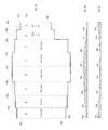
- an eye-shield substrate 602 is provided with even more electrically-isolated heating element regions A-H than in previous embodiments to enhance the degree to which the eye-shield may be controlled and further enhancing the degree to which even heating or custom heating may be accomplished across a still more irregularly-shaped eye-shield.
- an eye-shield having eight heating element regions: A, B, C, D, E, F, G and H ( 604 , 606 , 608 , 610 , 612 , 614 , 616 , 618 , respectively) with size values as shown.
- the resistivity of the heating element regions A-H of this embodiment of the invention have been normalized to provide even heating across the entire eye-shield substrate 602 either by using different thicknesses of heating element material (e.g., ITO) applied to the substrate as shown in FIG. 6 b at 620 , 622 , 624 , 626 , 628 , 630 , 632 , 634 , or by using different resistivity formulations of heating material applied to the substrate (e.g., 10-ohm per square at 800 angstroms thick ITO, 20-ohm per square at 800 angstroms thick ITO, etc.).
- a combination of these methods may be employed. Note that a thicker application of the same ITO material tends to decrease the resistivity of the material on a region as compared to a thinner application.
- the resistivity of the heating element regions A-H of this embodiment may be customized as shown in FIG. 6 c to provide lesser heating in the center of the eye-shield (e.g., at regions C-F) and greater heating on the outside of the eye-shield (e.g., at regions A-B and G-H)—or according to some other custom profile. As shown in FIG. 6 c , this is accomplished by changing the thickness of each region 636 , 638 , 640 , 642 , 644 , 646 , 648 , 650 , 652 of the eye-shield to vary the resistivity of that portion of the eye-shield.
- this may be accomplished by choosing different resistivity formulations of heating material applied to the substrate (e.g., 10-ohm per square at 800 angstroms thick ITO, 20-ohm per square at 800 angstroms thick ITO, etc.). Finally, a combination of these methods may be employed as well.
- the desired result may be achieved by varying the resistivity of different segments of the eye-shield by varying the thickness, by choosing a different formulation of heating material, or by utilizing PWM heating channel technology as disclosed in the PWM Application.
- the embodiment shown in FIG. 6 a comprising regions A-H may have normalized, or equalized, R values to balance power densities as described above using, for example, one or both of formulation selection and thickness application of heating material.
- one advantage illustrated by the embodiment shown in FIG. 6 a is that if, for example, a multichannel PWM heating source were to be used to vary the power density of the regions, the PWM system wouldn't have to compensate for undesirable hot spots because the lens has already been normalized. This, in turn allows for a greater range of control of the entire lens by the PWM, since part of the degree of adjustment available will not have been lost in compensating for overheating areas of the eye-shield.
- the foregoing resistivity per square values are calculated for even heating across the entire substrate 602 , and may be accomplished either by changing the effective voltage with PWM, or by changing the formulation or thickness of application of the heating material applied as described above. Further, it will be appreciated that the greater the specificity of regions, as for example shown and described in FIG. 8 , the greater control over the lens that may be achieved and the greater the degree of evenness may be achieved across the entire lens.
- FIGS. 7 a - 7 c there is provided part of an eye-shield substrate 702 having a plurality of contiguous heating element regions A-H ( 704 , 706 , 708 , 710 , 712 , 714 , 716 , 718 , respectively).
- the invention includes an embodiment such as that of FIG. 7 a wherein a single upper bus bar 754 , and a single lower bus bar 756 , may be used to connect with this plurality of contiguous heating element regions.
- FIG. 7 b a balanced heating eye-shield or screen is shown wherein, similarly to FIG. 6 b , the even heating may be accomplished by one or a combination of varying the thickness of the heating material applied and selection of different formulations of heating material for different areas.
- varying the thickness of the heating material for the present embodiment is preferable, since in this way a smoother transitioning of variation of resistivity across the lens may be achieved without banding.
- FIG. 7 b illustrates an evenly heating eye-shield comprising regions 720 , 722 , 724 , 726 , 728 , 730 , 732 , 734 , wherein the inner regions 724 , 726 , 728 , 730 are thicker than the outer regions 720 , 722 , 732 , 734 to provide normalized heating across the entire substrate similarly to that described previously in connection with FIG. 6 b .
- the transitions between the contiguous segments or regions of heating material are smoother, less stair-stepped, allowing for less contrast between regions and thus smoother power density transitions between regions.
- the power densities of the contiguous embodiment of the eye-shield shown in FIG. 7 b are continuously variable.
- FIG. 7 c there is shown a customized heated eye-shield having a plurality of contiguous heating elements 736 , 738 , 740 , 742 , 744 , 746 , 748 , 750 , 752 wherein, similarly to FIG. 6C , the custom heating profile provides for cooler segments in the middle areas 740 , 742 , 744 , 746 and warmer regions in the outer areas 736 , 738 , 750 , 752 .
- the power density transitions with this embodiment are less stair-stepped and more continuously variable across the eye-shield, thus providing smoother power density transition between these contiguous regions. Also, as with the eye-shield of FIGS.
- the embodiment of the invention shown in FIG. 7 c may be accomplished with a single power source, such as a single battery, or a single channel PWM, driving the single bus bars 754 , 756 .
- a single power source such as a single battery, or a single channel PWM, driving the single bus bars 754 , 756 .
- FIGS. 6 b , 6 c , 7 b and 7 c are for illustrative purposes only. And while an attempt has been made to show relative differences in thickness of application of heating material to scale, it will nevertheless be appreciated that since these thickness are on the order of hundreds of angstroms thick, the drawings represent rough approximations of relative thickness of material, not actual to-scale representations.
- FIG. 8 there is shown an eye-shield substrate 800 that is divided into even more, that is twenty four, heating regions, regions 802 , A-X, than previously-described embodiments.
- each of these heating regions 802 , A-X has been normalized as described above in that they either have even heating, or a desired custom profile.
- This embodiment of the invention clearly shows that over the bridge of the nose, the regions are less high (that is, they have a lesser value of H), and thus they would traditionally be prone to overheating without the present invention.
- multiple channels a-x such that multiple PWM channels may be used, as described in the PWM Application, to further specify and drive the eye-shield heating system in a way that conserves battery life.
- FIG. 8 illustrates the use of a plurality of bus bars, one for each channel to enable independent control of and power to each heating region 802 , A-X, and a single ground bus bar 806 .
- a single pulse-width modulator (PWM), single region fog prevention system 900 comprising a battery power source 902 having positive and negative terminals 904 , 906 , circuit wires 908 , 910 , PWM 912 (which generates signal 914 ), MOSFET switch 916 , eye-shield 918 , heating element 920 , a microcomputer (MCU) 922 , a heater voltage sense resistor 924 , a heater current sense resistor 926 , a sense voltage 928 , and a heater current voltage sense 930 .
- PWM pulse-width modulator
- a circuit 908 , 910 interconnects the battery power source 902 , the PWM 912 , the MCU 922 , the MOSFET switch 916 , the heater current sense resistor 926 , the sense voltage 928 , the heater voltage sense resistor 924 and the heating element 920 , the MCU 922 gathers information about the heater voltage sense resistor 924 and determines the heating element 920 resistance. The MCU 922 then relays information based on the heating element 920 resistance to the PWM 912 in order to adjust current which the PWM 912 controls.
- Controlling the current will in turn help to maintain temperature of the heating element 920 from one eye-shield defogging system 900 to another, despite variations in heating element resistivity from one eye-shield to the next, or from one eye-shield heating region to another, for example among regions A-H of FIG. 6 a , regions A-H of FIG. 7 a , or regions A-X of FIG. 8 , to a temperature that is above an anticipated dew point temperature of an operating environment, despite variations in heating element resistivity from one region to the next.
- FIG. 9 is shown as a single PWM, single region fog prevention system, it will be appreciated that the invention may be applied to eye-shields having more than one region, as has been shown in FIGS. 2-8 , where there is a progression of less complex to more complex embodiments of the invention having more than one region on the eye-shield, in order to create uniformity, or consistently accurate power densities for a custom heating profile, while heating each eye-shield region relative to each other eye-shield region, despite variations in resistivity of the heating elements of each of the regions.
- the invention may be applied to ensure that multiple eye-shields have consistent properties as experienced by users from one eye-shield to another eye-shield, despite variations in resistivity of the heating elements on each of the eye-shields. It will be appreciated that there will be other combinations of the elements to form a heated eye-shield lens which would not depart from the scope and spirit of the invention as set forth in the claims portion of this specification.
- the MCU 922 is shown as a device which comprises a potentiometer and has an internal reference voltage (vref) that is lower than the battery minimum usable voltage and provides an output voltage (input voltage to the PWM 912 ), the output voltage from the MCU 922 being some voltage between zero and the reference voltage (vref) based upon the setting of the potentiometer. Responsive to the MCU 922 , the PWM 912 produces a corresponding percentage on/off signal that can be varied as a result of output from the MCU 922 .
- vref internal reference voltage
- a control MCU responsive to a MORE (increase) button and responsive to a LESS (decrease) button directly varies the duty cycle of the PWM 912 and thereby varies the amount of current delivered to the heating element 920 without requiring an intermediate voltage reference.
- An output line 932 carrying the output voltage of the MCU 922 is operatively connected between the MCU 922 and the PWM 912 .
- the PWM 912 translates the output voltage from the MCU 922 into a signal having a duty cycle corresponding and proportional to the magnitude of the voltage into the PWM 912 .
- the duty cycle of the PWM's 912 output will therefore vary in relation to the voltage in from the MCU 922 such that a near-zero input voltage from the MCU 922 to the PWM 912 will result in a near-zero percent on/near 100 percent off duty cycle output of the PWM 912 .
- the MCU 922 enables varied output duty cycles of the PWM 912 .
- the defogging ability of the heating element 920 is determined by the amount of power supplied to the heating element 920 .
- Heating element power is a function of the voltage applied across the heating element 920 , the amount of time the voltage is applied to the heating element 920 which is established by the duty cycle of the PWM 912 , and electrical resistance of the heating element 920 .
- the heating element power is governed by the following equation:
- Heating ⁇ ⁇ Power ( V 2 R ) ⁇ ( Duty ⁇ ⁇ Cycle 100 )
- V voltage
- R heating element 920 resistance
- duty cycle is expressed as a percent of switching element “on time”. Therefore, as shown by this equation, actual heating power for heating element 920 in any given eye-shield 918 varies not just with voltage and duty cycle, but also with the resistance of heating element 920 .
- the duty cycle of the PWM 912 is increased or decreased to compensate for varying resistances of the heating element 920 .
- the MCU 922 In order to correctly compensate for variations of heating element 920 resistance, the MCU 922 must first establish the actual value of resistance of heating element 920 .
- the MCU 922 first establishes the actual resistance by monitoring and obtaining values for the sense voltage 928 through the heater voltage sense resistor 924 that is applied to the heating element 920 , and also monitoring the heater current sense voltage 930 that is applied through the heater current sense resistor 926 that has a fixed resistance. The MCU 922 will do this whenever the PWM 912 is in the “on” state.
- the MCU 922 After monitoring and obtaining a value for the sense voltage 928 and heater current sense voltage 930 , and already knowing a value for the heater voltage sense resistor 924 , the MCU 922 then uses these voltage values and resistance values to determine the heating element resistance using the following equation.
- Heating ⁇ ⁇ Element ⁇ ⁇ Resistance Heater ⁇ ⁇ Current ⁇ ⁇ Sense ⁇ ⁇ Voltage ⁇ ⁇ 930 ( Sense ⁇ ⁇ Voltage ⁇ ⁇ 928 Heater ⁇ ⁇ Voltage ⁇ ⁇ Sense ⁇ ⁇ Resistance ⁇ ⁇ 924 )
- the MCU 922 will relay a signal to the PWM to adjust the duty cycle by a multiplying factor, called a PWM adjustment factor.
- the PWM adjustment factor is derived from the heating element resistance that is calculated by the MCU 922 using the following equation:
- PWM ⁇ ⁇ Adjustment ⁇ ⁇ Factor Heating ⁇ ⁇ Element ⁇ ⁇ Resistance Nominal ⁇ ⁇ Resistance where nominal resistance is a known and a desired value of resistance for the heating element 920 .
- a two-dimensional look-up table is employed, an example of which is seen in FIG. 10 .
- the look-up table creates a mapping of PWM adjustment factors that relates to heating element resistance values. For example, in an eye-shield design where the nominal heating element 920 resistance is ten ohms, where also there is a known variation of resistance from one eye-shield to another eye-shield or one region of an eye-shield to another region of the same eye-shield of plus or minus twenty percent, then a look-up might look as it appears in FIG. 10 .
- the system would compensate for the variance by supplying a PWM adjustment factor of 0.80 as described previously in connection with the look-up table of FIG. 10 .
- a heating element 920 resistance of twelve ohms would be compensated by the system with a PWM adjustment factor of 1.20.
- the nominal value of the heating element 920 resistance is ten ohms.
- other nominal resistances and measured resistance ranges can be used, and PWM adjustment factors corresponding to other nominal resistances and measured resistance ranges are found using the equation for PWM adjustment factors.
- the number of heating element resistances expressed in the table is variable, and is dependent upon the specificity with which PWM 912 adjustments should be made for a given application. It might be desirable in some circumstances to have a fine granularity of PWM adjustments so that the heating element 920 stays at a precise temperature. In another circumstance, a broad granularity of PWM adjustments might be more suitable when consistent temperature is not necessary.
- this combination of heating element 920 resistance sensing and corresponding PWM 912 duty cycle adjustment allows the eye-shield heating element 920 to maintain constant heat, and the ability to compensate for variations in resistance encountered from one eye-shield region to another, and one eye-shield to another eye-shield as may be determined, for example, by testing resistivity of a batch of eye-shields.
Abstract
Description
Pd=E 2 /R·H 2,
where Pd is the power density, E is the voltage, R is resistance per square, and H is the height (distance between bus bars).
Where V is voltage, and R is
where nominal resistance is a known and a desired value of resistance for the
Claims (4)
Priority Applications (3)
| Application Number | Priority Date | Filing Date | Title |
|---|---|---|---|
| US14/556,128 US9072591B2 (en) | 2012-02-16 | 2014-11-29 | Micro-current sensing auto-adjusting heater system for eye-shield |
| PCT/US2015/059498 WO2016085636A1 (en) | 2014-11-29 | 2015-11-06 | Micro-current sensing eye-shield heater system |
| JP2017528447A JP2018504626A (en) | 2014-11-29 | 2015-11-06 | Micro current detection protection glasses heating body system |
Applications Claiming Priority (3)
| Application Number | Priority Date | Filing Date | Title |
|---|---|---|---|
| US13/397,691 US8566962B2 (en) | 2012-02-16 | 2012-02-16 | PWM heating system for eye shield |
| US14/040,683 US9210737B2 (en) | 2012-02-16 | 2013-09-29 | Multiregion heated eye shield |
| US14/556,128 US9072591B2 (en) | 2012-02-16 | 2014-11-29 | Micro-current sensing auto-adjusting heater system for eye-shield |
Related Parent Applications (1)
| Application Number | Title | Priority Date | Filing Date |
|---|---|---|---|
| US14/040,683 Continuation-In-Part US9210737B2 (en) | 2012-02-16 | 2013-09-29 | Multiregion heated eye shield |
Publications (2)
| Publication Number | Publication Date |
|---|---|
| US20150121610A1 US20150121610A1 (en) | 2015-05-07 |
| US9072591B2 true US9072591B2 (en) | 2015-07-07 |
Family
ID=53005834
Family Applications (1)
| Application Number | Title | Priority Date | Filing Date |
|---|---|---|---|
| US14/556,128 Active US9072591B2 (en) | 2012-02-16 | 2014-11-29 | Micro-current sensing auto-adjusting heater system for eye-shield |
Country Status (1)
| Country | Link |
|---|---|
| US (1) | US9072591B2 (en) |
Cited By (1)
| Publication number | Priority date | Publication date | Assignee | Title |
|---|---|---|---|---|
| US10398601B2 (en) * | 2015-10-23 | 2019-09-03 | Abominable Labs, Llc | Immersive experience headset adapted to prevent fogging |
Families Citing this family (9)
| Publication number | Priority date | Publication date | Assignee | Title |
|---|---|---|---|---|
| WO2013078442A1 (en) * | 2011-11-25 | 2013-05-30 | David Mcculloch | Modular anti-fog goggle system |
| CN204666991U (en) * | 2015-05-21 | 2015-09-23 | 刘东光 | Visual heating comprehensive health-care glasses |
| US20160359207A1 (en) * | 2015-06-08 | 2016-12-08 | Abominable Labs, Llc | Thermally-protected chemical-cell battery system |
| DE102015114507A1 (en) * | 2015-08-31 | 2017-03-02 | Polyic Gmbh & Co. Kg | Heatable laminated body, method for applying and heated disc |
| US10111780B2 (en) | 2015-10-23 | 2018-10-30 | Abominable Labs, Llc | Goggle lens and face gasket engagement system |
| US10729177B2 (en) * | 2016-07-31 | 2020-08-04 | Altria Client Services Llc | Electronic vaping device, battery section, and charger |
| JP6589897B2 (en) * | 2017-01-25 | 2019-10-16 | トヨタ自動車株式会社 | Windshield heating device for in-vehicle camera |
| CN108235467A (en) * | 2017-12-13 | 2018-06-29 | 苏州长风航空电子有限公司 | A kind of display screen heats demister and defogging method automatically |
| US11039505B1 (en) * | 2020-04-06 | 2021-06-15 | 7788746 Canada, Inc. | Method, equation, design, and construct to provide uniform heating for three-dimensional and various shaped heaters with improved busbar designs |
Citations (23)
| Publication number | Priority date | Publication date | Assignee | Title |
|---|---|---|---|---|
| US3160735A (en) * | 1963-02-27 | 1964-12-08 | Aufricht Gustave | Anti-fogging eyeglasses |
| US4357524A (en) | 1980-01-29 | 1982-11-02 | Westinghouse Electric Corp. | Electrical heater controller for aircraft window heat control |
| US4584721A (en) | 1982-04-26 | 1986-04-29 | Yamamoto Kogaku Co., Ltd. | Device for use in helmet for preventing fogging by electric heating |
| US4868929A (en) | 1988-05-09 | 1989-09-26 | Curcio Philip L | Electrically heated ski goggles |
| US4942629A (en) | 1988-05-30 | 1990-07-24 | Optyl Eyewear Fashion International Corporation | Ski goggles with heated lens |
| US5105067A (en) | 1989-09-08 | 1992-04-14 | Environwear, Inc. | Electronic control system and method for cold weather garment |
| US5319397A (en) * | 1992-09-21 | 1994-06-07 | Ryden William D | Defogging eyeglasses |
| US5351339A (en) | 1993-02-03 | 1994-10-04 | 546401 Ontario Limited | Double lens electric shield |
| US5363153A (en) * | 1991-10-07 | 1994-11-08 | Bailiff Clealen D | Comfort zone heating apparatus for glasses or the like |
| US5459533A (en) | 1993-11-12 | 1995-10-17 | See Clear Eyewear Inc. | Defogging eye wear |
| US5471036A (en) * | 1991-12-02 | 1995-11-28 | Sperbeck; Scott W. | Goggle defogging system with transparent indium-tin-oxide heating layer disposed on a lens |
| US5778689A (en) | 1997-05-19 | 1998-07-14 | Beatenbough; Bryan | System for maintaining refrigeration doors free of frost and condensation |
| US6470696B1 (en) | 2001-09-18 | 2002-10-29 | Valerie Palfy | Devices and methods for sensing condensation conditions and for removing condensation from surfaces |
| CA2381876A1 (en) * | 2001-09-26 | 2003-03-26 | Tokuichiro Hasegawa | Eye mask |
| US20030091089A1 (en) | 2001-11-14 | 2003-05-15 | Krausse George J. | Thermal condensate reducer for optical devices |
| US6704944B2 (en) | 2001-05-08 | 2004-03-16 | Yamamoto Kogaku Co., Ltd. | Sports goggles |
| US6896366B2 (en) | 2003-08-14 | 2005-05-24 | Npf Limited | Goggles |
| US6927368B2 (en) | 2003-03-27 | 2005-08-09 | Lexmark International, Inc. | Method and apparatus for controlling power to a heater element using dual pulse width modulation control |
| US20060289458A1 (en) | 2005-05-17 | 2006-12-28 | Halla Climate Control Corporation | Fogging detecting system for an automotive vehicle and method for controlling the system |
| US7387022B1 (en) | 2007-05-02 | 2008-06-17 | Honeywell International Inc. | Thermal mass flow transducer including PWM-type heater current driver |
| US20080290081A1 (en) | 2005-11-08 | 2008-11-27 | Nel Technologies Limited | Anti-Fogging Device and Anti-Fogging Viewing Member |
| US7648234B2 (en) | 2006-04-28 | 2010-01-19 | Kimberly-Clark Worldwide, Inc. | Eyewear with heating elements |
| US20130043233A1 (en) | 2011-08-16 | 2013-02-21 | Jeremy Alan Elser | Device for active heating of transparent materials |
Family Cites Families (1)
| Publication number | Priority date | Publication date | Assignee | Title |
|---|---|---|---|---|
| GB2381876B (en) * | 1998-09-30 | 2003-06-25 | Snap On Equipment Ltd | Method and apparatus for automotive and other battery testing |
-
2014
- 2014-11-29 US US14/556,128 patent/US9072591B2/en active Active
Patent Citations (26)
| Publication number | Priority date | Publication date | Assignee | Title |
|---|---|---|---|---|
| US3160735A (en) * | 1963-02-27 | 1964-12-08 | Aufricht Gustave | Anti-fogging eyeglasses |
| US4357524A (en) | 1980-01-29 | 1982-11-02 | Westinghouse Electric Corp. | Electrical heater controller for aircraft window heat control |
| US4584721A (en) | 1982-04-26 | 1986-04-29 | Yamamoto Kogaku Co., Ltd. | Device for use in helmet for preventing fogging by electric heating |
| US4868929A (en) | 1988-05-09 | 1989-09-26 | Curcio Philip L | Electrically heated ski goggles |
| US4942629A (en) | 1988-05-30 | 1990-07-24 | Optyl Eyewear Fashion International Corporation | Ski goggles with heated lens |
| US5105067A (en) | 1989-09-08 | 1992-04-14 | Environwear, Inc. | Electronic control system and method for cold weather garment |
| US5363153A (en) * | 1991-10-07 | 1994-11-08 | Bailiff Clealen D | Comfort zone heating apparatus for glasses or the like |
| US5471036A (en) * | 1991-12-02 | 1995-11-28 | Sperbeck; Scott W. | Goggle defogging system with transparent indium-tin-oxide heating layer disposed on a lens |
| US5319397A (en) * | 1992-09-21 | 1994-06-07 | Ryden William D | Defogging eyeglasses |
| US5351339A (en) | 1993-02-03 | 1994-10-04 | 546401 Ontario Limited | Double lens electric shield |
| US5459533A (en) | 1993-11-12 | 1995-10-17 | See Clear Eyewear Inc. | Defogging eye wear |
| US5778689A (en) | 1997-05-19 | 1998-07-14 | Beatenbough; Bryan | System for maintaining refrigeration doors free of frost and condensation |
| US6704944B2 (en) | 2001-05-08 | 2004-03-16 | Yamamoto Kogaku Co., Ltd. | Sports goggles |
| US6470696B1 (en) | 2001-09-18 | 2002-10-29 | Valerie Palfy | Devices and methods for sensing condensation conditions and for removing condensation from surfaces |
| US20040050076A1 (en) | 2001-09-18 | 2004-03-18 | Valerie Palfy | Devices and methods for sensing condensation conditions and for preventing and removing condensation from surfaces |
| US20040050072A1 (en) | 2001-09-18 | 2004-03-18 | Valerie Palfy | Devices and methods for sensing condensation conditions and for preventing and removing condensation from surfaces |
| CA2381876A1 (en) * | 2001-09-26 | 2003-03-26 | Tokuichiro Hasegawa | Eye mask |
| US20030091089A1 (en) | 2001-11-14 | 2003-05-15 | Krausse George J. | Thermal condensate reducer for optical devices |
| US6927368B2 (en) | 2003-03-27 | 2005-08-09 | Lexmark International, Inc. | Method and apparatus for controlling power to a heater element using dual pulse width modulation control |
| US6896366B2 (en) | 2003-08-14 | 2005-05-24 | Npf Limited | Goggles |
| US20060289458A1 (en) | 2005-05-17 | 2006-12-28 | Halla Climate Control Corporation | Fogging detecting system for an automotive vehicle and method for controlling the system |
| US20080290081A1 (en) | 2005-11-08 | 2008-11-27 | Nel Technologies Limited | Anti-Fogging Device and Anti-Fogging Viewing Member |
| US8399805B2 (en) | 2005-11-08 | 2013-03-19 | Nel Technologies Limited | Anti-fogging device and anti-fogging viewing member |
| US7648234B2 (en) | 2006-04-28 | 2010-01-19 | Kimberly-Clark Worldwide, Inc. | Eyewear with heating elements |
| US7387022B1 (en) | 2007-05-02 | 2008-06-17 | Honeywell International Inc. | Thermal mass flow transducer including PWM-type heater current driver |
| US20130043233A1 (en) | 2011-08-16 | 2013-02-21 | Jeremy Alan Elser | Device for active heating of transparent materials |
Cited By (1)
| Publication number | Priority date | Publication date | Assignee | Title |
|---|---|---|---|---|
| US10398601B2 (en) * | 2015-10-23 | 2019-09-03 | Abominable Labs, Llc | Immersive experience headset adapted to prevent fogging |
Also Published As
| Publication number | Publication date |
|---|---|
| US20150121610A1 (en) | 2015-05-07 |
Similar Documents
| Publication | Publication Date | Title |
|---|---|---|
| US9210737B2 (en) | Multiregion heated eye shield | |
| US9072591B2 (en) | Micro-current sensing auto-adjusting heater system for eye-shield | |
| EP2814433B1 (en) | Pwm heating system for eye shield | |
| AU2014324661A1 (en) | Multiregion heated eye shield | |
| US10398601B2 (en) | Immersive experience headset adapted to prevent fogging | |
| US9419520B2 (en) | Battery compensation system using PWM | |
| US9808375B2 (en) | Power-saving method for defogging an eye-shield | |
| AU2014329396B2 (en) | Battery compensation system using PWM | |
| US20180256399A1 (en) | Modular anti-fog goggle system | |
| US9678367B2 (en) | Multi-pane, multi-geometry goggle eye-shield | |
| WO2016085636A1 (en) | Micro-current sensing eye-shield heater system | |
| WO2016036575A1 (en) | Power-saving method for defogging eye-shield | |
| US20240082062A1 (en) | Goggle lens |
Legal Events
| Date | Code | Title | Description |
|---|---|---|---|
| AS | Assignment |
Owner name: ABOMINABLE LABS, LLC, OREGON Free format text: ASSIGNMENT OF ASSIGNORS INTEREST;ASSIGNORS:CORNELIUS, JACK C.;O'MALLEY, VINCENT;REEL/FRAME:034571/0647 Effective date: 20141222 |
|
| STCF | Information on status: patent grant |
Free format text: PATENTED CASE |
|
| MAFP | Maintenance fee payment |
Free format text: PAYMENT OF MAINTENANCE FEE, 4TH YR, SMALL ENTITY (ORIGINAL EVENT CODE: M2551); ENTITY STATUS OF PATENT OWNER: SMALL ENTITY Year of fee payment: 4 |
|
| AS | Assignment |
Owner name: MCCULLOCH, DAVID C., OREGON Free format text: ASSIGNMENT OF ASSIGNORS INTEREST;ASSIGNOR:KENNETH S. EILER PC AS ASSIGNEE UNDER AN ASSIGNMENT FOR THE BENEFIT OF CREDITORS, EXECUTED BY ABOM, INC;REEL/FRAME:061054/0258 Effective date: 20220829 |
|
| AS | Assignment |
Owner name: MCCULLOCH, DAVID C., OREGON Free format text: CORRECTIVE ASSIGNMENT TO CORRECT THE THE EXECUTION DATE PREVIOUSLY RECORDED AT REEL: 061054 FRAME: 0258. ASSIGNOR(S) HEREBY CONFIRMS THE ASSIGNMENT;ASSIGNOR:KENNETH S. EILER PC AS ASSIGNEE UNDER AN ASSIGNMENT FOR THE BENEFIT OF CREDITORS, EXECUTED BY ABOM, INC;REEL/FRAME:062227/0280 Effective date: 20220831 Owner name: TEMPEST OPTICS LLC, OREGON Free format text: ASSIGNMENT OF ASSIGNORS INTEREST;ASSIGNOR:MCCULLOCH, DAVID C.;REEL/FRAME:061461/0315 Effective date: 20221005 |
|
| MAFP | Maintenance fee payment |
Free format text: PAYMENT OF MAINTENANCE FEE, 8TH YR, SMALL ENTITY (ORIGINAL EVENT CODE: M2552); ENTITY STATUS OF PATENT OWNER: SMALL ENTITY Year of fee payment: 8 |