US8965516B2 - System and method for treatment of pain related to limb joint replacement surgery - Google Patents
System and method for treatment of pain related to limb joint replacement surgery Download PDFInfo
- Publication number
- US8965516B2 US8965516B2 US13/791,710 US201313791710A US8965516B2 US 8965516 B2 US8965516 B2 US 8965516B2 US 201313791710 A US201313791710 A US 201313791710A US 8965516 B2 US8965516 B2 US 8965516B2
- Authority
- US
- United States
- Prior art keywords
- pain
- nerve
- electrical stimulation
- electrode
- joint replacement
- Prior art date
- Legal status (The legal status is an assumption and is not a legal conclusion. Google has not performed a legal analysis and makes no representation as to the accuracy of the status listed.)
- Active
Links
- 208000002193 Pain Diseases 0.000 title claims abstract description 117
- 230000036407 pain Effects 0.000 title claims abstract description 112
- 238000000034 method Methods 0.000 title claims abstract description 66
- 238000001356 surgical procedure Methods 0.000 title claims abstract description 56
- 238000011282 treatment Methods 0.000 title description 14
- 210000000578 peripheral nerve Anatomy 0.000 claims abstract description 72
- 210000003414 extremity Anatomy 0.000 claims abstract description 46
- 208000035824 paresthesia Diseases 0.000 claims abstract description 46
- 238000011883 total knee arthroplasty Methods 0.000 claims abstract description 3
- 230000000638 stimulation Effects 0.000 claims description 114
- 210000005036 nerve Anatomy 0.000 claims description 93
- 210000001519 tissue Anatomy 0.000 claims description 45
- 210000003099 femoral nerve Anatomy 0.000 claims description 22
- 210000003497 sciatic nerve Anatomy 0.000 claims description 19
- 230000007383 nerve stimulation Effects 0.000 claims description 15
- 230000000763 evoking effect Effects 0.000 claims description 13
- 210000004394 hip joint Anatomy 0.000 claims description 5
- 210000000629 knee joint Anatomy 0.000 claims description 5
- 210000004239 obturator nerve Anatomy 0.000 claims description 3
- 210000000707 wrist Anatomy 0.000 claims description 3
- 210000000544 articulatio talocruralis Anatomy 0.000 claims description 2
- 210000001513 elbow Anatomy 0.000 claims description 2
- 210000001145 finger joint Anatomy 0.000 claims description 2
- 210000002832 shoulder Anatomy 0.000 claims description 2
- 210000001226 toe joint Anatomy 0.000 claims description 2
- 230000035807 sensation Effects 0.000 abstract description 26
- 208000004550 Postoperative Pain Diseases 0.000 abstract description 12
- 230000004936 stimulating effect Effects 0.000 abstract description 6
- 210000003205 muscle Anatomy 0.000 description 29
- 210000003491 skin Anatomy 0.000 description 26
- 238000013459 approach Methods 0.000 description 22
- 210000000689 upper leg Anatomy 0.000 description 19
- 210000002988 lumbosacral plexus Anatomy 0.000 description 18
- 210000001032 spinal nerve Anatomy 0.000 description 16
- 230000004044 response Effects 0.000 description 14
- 238000003780 insertion Methods 0.000 description 13
- 230000037431 insertion Effects 0.000 description 13
- 230000001953 sensory effect Effects 0.000 description 12
- 239000000835 fiber Substances 0.000 description 11
- 210000003314 quadriceps muscle Anatomy 0.000 description 11
- 238000004873 anchoring Methods 0.000 description 10
- 210000002414 leg Anatomy 0.000 description 8
- 238000012360 testing method Methods 0.000 description 8
- 238000002560 therapeutic procedure Methods 0.000 description 8
- 241001465754 Metazoa Species 0.000 description 7
- 230000003387 muscular Effects 0.000 description 7
- 210000001428 peripheral nervous system Anatomy 0.000 description 7
- 238000002604 ultrasonography Methods 0.000 description 7
- 210000003169 central nervous system Anatomy 0.000 description 6
- 210000002683 foot Anatomy 0.000 description 6
- 238000003384 imaging method Methods 0.000 description 6
- 230000008569 process Effects 0.000 description 6
- 230000001105 regulatory effect Effects 0.000 description 6
- 238000002646 transcutaneous electrical nerve stimulation Methods 0.000 description 6
- 230000001154 acute effect Effects 0.000 description 5
- 230000003444 anaesthetic effect Effects 0.000 description 5
- 239000004020 conductor Substances 0.000 description 5
- 210000000527 greater trochanter Anatomy 0.000 description 5
- 230000001965 increasing effect Effects 0.000 description 5
- 210000003127 knee Anatomy 0.000 description 5
- 210000003041 ligament Anatomy 0.000 description 5
- 239000000463 material Substances 0.000 description 5
- 230000001537 neural effect Effects 0.000 description 5
- 238000011084 recovery Methods 0.000 description 5
- 210000002972 tibial nerve Anatomy 0.000 description 5
- 230000003247 decreasing effect Effects 0.000 description 4
- 238000002594 fluoroscopy Methods 0.000 description 4
- 230000030214 innervation Effects 0.000 description 4
- 210000004126 nerve fiber Anatomy 0.000 description 4
- 210000002027 skeletal muscle Anatomy 0.000 description 4
- 230000000392 somatic effect Effects 0.000 description 4
- 206010001497 Agitation Diseases 0.000 description 3
- 206010052804 Drug tolerance Diseases 0.000 description 3
- 208000027418 Wounds and injury Diseases 0.000 description 3
- 208000005298 acute pain Diseases 0.000 description 3
- 239000000730 antalgic agent Substances 0.000 description 3
- 230000008901 benefit Effects 0.000 description 3
- 230000002051 biphasic effect Effects 0.000 description 3
- 210000001217 buttock Anatomy 0.000 description 3
- 230000008859 change Effects 0.000 description 3
- 238000004891 communication Methods 0.000 description 3
- 230000007423 decrease Effects 0.000 description 3
- 238000010586 diagram Methods 0.000 description 3
- 230000000694 effects Effects 0.000 description 3
- 210000001105 femoral artery Anatomy 0.000 description 3
- 230000006870 function Effects 0.000 description 3
- 230000026781 habituation Effects 0.000 description 3
- 210000003141 lower extremity Anatomy 0.000 description 3
- 230000005012 migration Effects 0.000 description 3
- 238000013508 migration Methods 0.000 description 3
- 238000012986 modification Methods 0.000 description 3
- 230000004048 modification Effects 0.000 description 3
- 230000004118 muscle contraction Effects 0.000 description 3
- 210000000653 nervous system Anatomy 0.000 description 3
- 230000007115 recruitment Effects 0.000 description 3
- 238000002694 regional anesthesia Methods 0.000 description 3
- 210000000278 spinal cord Anatomy 0.000 description 3
- 210000000273 spinal nerve root Anatomy 0.000 description 3
- 230000001225 therapeutic effect Effects 0.000 description 3
- CPKVUHPKYQGHMW-UHFFFAOYSA-N 1-ethenylpyrrolidin-2-one;molecular iodine Chemical compound II.C=CN1CCCC1=O CPKVUHPKYQGHMW-UHFFFAOYSA-N 0.000 description 2
- RZVAJINKPMORJF-UHFFFAOYSA-N Acetaminophen Chemical compound CC(=O)NC1=CC=C(O)C=C1 RZVAJINKPMORJF-UHFFFAOYSA-N 0.000 description 2
- 208000036829 Device dislocation Diseases 0.000 description 2
- 208000028389 Nerve injury Diseases 0.000 description 2
- 206010052428 Wound Diseases 0.000 description 2
- 230000003187 abdominal effect Effects 0.000 description 2
- 229940035676 analgesics Drugs 0.000 description 2
- 238000005452 bending Methods 0.000 description 2
- 210000000988 bone and bone Anatomy 0.000 description 2
- 210000003461 brachial plexus Anatomy 0.000 description 2
- 244000309466 calf Species 0.000 description 2
- 210000002808 connective tissue Anatomy 0.000 description 2
- 230000006378 damage Effects 0.000 description 2
- 210000003195 fascia Anatomy 0.000 description 2
- 239000007943 implant Substances 0.000 description 2
- 238000002513 implantation Methods 0.000 description 2
- 230000006872 improvement Effects 0.000 description 2
- 208000015181 infectious disease Diseases 0.000 description 2
- 230000007774 longterm Effects 0.000 description 2
- 239000002184 metal Substances 0.000 description 2
- 239000004081 narcotic agent Substances 0.000 description 2
- 230000008764 nerve damage Effects 0.000 description 2
- 229940021182 non-steroidal anti-inflammatory drug Drugs 0.000 description 2
- 210000000056 organ Anatomy 0.000 description 2
- 230000002093 peripheral effect Effects 0.000 description 2
- 210000004345 peroneal nerve Anatomy 0.000 description 2
- 238000012216 screening Methods 0.000 description 2
- 210000000697 sensory organ Anatomy 0.000 description 2
- 241000894007 species Species 0.000 description 2
- 210000000546 superficial inguinal ring Anatomy 0.000 description 2
- 210000000115 thoracic cavity Anatomy 0.000 description 2
- 238000012549 training Methods 0.000 description 2
- 238000011144 upstream manufacturing Methods 0.000 description 2
- 230000001755 vocal effect Effects 0.000 description 2
- 206010002091 Anaesthesia Diseases 0.000 description 1
- GHXZTYHSJHQHIJ-UHFFFAOYSA-N Chlorhexidine Chemical compound C=1C=C(Cl)C=CC=1NC(N)=NC(N)=NCCCCCCN=C(N)N=C(N)NC1=CC=C(Cl)C=C1 GHXZTYHSJHQHIJ-UHFFFAOYSA-N 0.000 description 1
- 208000000094 Chronic Pain Diseases 0.000 description 1
- 206010010774 Constipation Diseases 0.000 description 1
- 206010011985 Decubitus ulcer Diseases 0.000 description 1
- 206010012335 Dependence Diseases 0.000 description 1
- LFQSCWFLJHTTHZ-UHFFFAOYSA-N Ethanol Chemical compound CCO LFQSCWFLJHTTHZ-UHFFFAOYSA-N 0.000 description 1
- 206010073306 Exposure to radiation Diseases 0.000 description 1
- 208000004547 Hallucinations Diseases 0.000 description 1
- 206010019233 Headaches Diseases 0.000 description 1
- 241000282412 Homo Species 0.000 description 1
- 206010065390 Inflammatory pain Diseases 0.000 description 1
- 241001313288 Labia Species 0.000 description 1
- 241001484259 Lacuna Species 0.000 description 1
- NNJVILVZKWQKPM-UHFFFAOYSA-N Lidocaine Chemical compound CCN(CC)CC(=O)NC1=C(C)C=CC=C1C NNJVILVZKWQKPM-UHFFFAOYSA-N 0.000 description 1
- 241000489861 Maximus Species 0.000 description 1
- 206010028347 Muscle twitching Diseases 0.000 description 1
- 206010028813 Nausea Diseases 0.000 description 1
- 208000001294 Nociceptive Pain Diseases 0.000 description 1
- 241000237503 Pectinidae Species 0.000 description 1
- 239000004642 Polyimide Substances 0.000 description 1
- 229920000153 Povidone-iodine Polymers 0.000 description 1
- 206010040880 Skin irritation Diseases 0.000 description 1
- 208000013738 Sleep Initiation and Maintenance disease Diseases 0.000 description 1
- 206010041349 Somnolence Diseases 0.000 description 1
- 208000002847 Surgical Wound Diseases 0.000 description 1
- 208000003443 Unconsciousness Diseases 0.000 description 1
- 206010047700 Vomiting Diseases 0.000 description 1
- 210000001015 abdomen Anatomy 0.000 description 1
- 210000003815 abdominal wall Anatomy 0.000 description 1
- 230000009471 action Effects 0.000 description 1
- 230000003213 activating effect Effects 0.000 description 1
- 230000004913 activation Effects 0.000 description 1
- 239000000853 adhesive Substances 0.000 description 1
- 230000001070 adhesive effect Effects 0.000 description 1
- 238000013019 agitation Methods 0.000 description 1
- 230000004075 alteration Effects 0.000 description 1
- 230000037005 anaesthesia Effects 0.000 description 1
- 210000003484 anatomy Anatomy 0.000 description 1
- 210000003423 ankle Anatomy 0.000 description 1
- 230000002421 anti-septic effect Effects 0.000 description 1
- 230000009118 appropriate response Effects 0.000 description 1
- 238000000429 assembly Methods 0.000 description 1
- 230000000712 assembly Effects 0.000 description 1
- 230000002567 autonomic effect Effects 0.000 description 1
- 229940064804 betadine Drugs 0.000 description 1
- 229920000249 biocompatible polymer Polymers 0.000 description 1
- 239000003181 biological factor Substances 0.000 description 1
- 210000004204 blood vessel Anatomy 0.000 description 1
- 210000004556 brain Anatomy 0.000 description 1
- 239000002775 capsule Substances 0.000 description 1
- 210000005056 cell body Anatomy 0.000 description 1
- 210000001773 cervical plexus Anatomy 0.000 description 1
- 239000003795 chemical substances by application Substances 0.000 description 1
- 210000000038 chest Anatomy 0.000 description 1
- 229960003260 chlorhexidine Drugs 0.000 description 1
- 230000003750 conditioning effect Effects 0.000 description 1
- 229920001940 conductive polymer Polymers 0.000 description 1
- 238000010276 construction Methods 0.000 description 1
- 230000008602 contraction Effects 0.000 description 1
- 230000002596 correlated effect Effects 0.000 description 1
- 230000000994 depressogenic effect Effects 0.000 description 1
- 239000000645 desinfectant Substances 0.000 description 1
- 206010012601 diabetes mellitus Diseases 0.000 description 1
- 208000002173 dizziness Diseases 0.000 description 1
- 239000012636 effector Substances 0.000 description 1
- 229920001971 elastomer Polymers 0.000 description 1
- 239000000806 elastomer Substances 0.000 description 1
- 210000000109 fascia lata Anatomy 0.000 description 1
- 210000000501 femur body Anatomy 0.000 description 1
- 210000000245 forearm Anatomy 0.000 description 1
- 210000004907 gland Anatomy 0.000 description 1
- 210000004013 groin Anatomy 0.000 description 1
- 210000004247 hand Anatomy 0.000 description 1
- 231100000869 headache Toxicity 0.000 description 1
- 230000035876 healing Effects 0.000 description 1
- 230000036541 health Effects 0.000 description 1
- 210000000548 hind-foot Anatomy 0.000 description 1
- 210000001624 hip Anatomy 0.000 description 1
- 210000003692 ilium Anatomy 0.000 description 1
- 230000002757 inflammatory effect Effects 0.000 description 1
- 208000014674 injury Diseases 0.000 description 1
- 206010022437 insomnia Diseases 0.000 description 1
- 230000002452 interceptive effect Effects 0.000 description 1
- 238000007918 intramuscular administration Methods 0.000 description 1
- 230000003447 ipsilateral effect Effects 0.000 description 1
- 210000001503 joint Anatomy 0.000 description 1
- 229960004194 lidocaine Drugs 0.000 description 1
- 239000003589 local anesthetic agent Substances 0.000 description 1
- 210000004705 lumbosacral region Anatomy 0.000 description 1
- 210000001365 lymphatic vessel Anatomy 0.000 description 1
- 238000012423 maintenance Methods 0.000 description 1
- 239000007769 metal material Substances 0.000 description 1
- 230000003533 narcotic effect Effects 0.000 description 1
- 230000008693 nausea Effects 0.000 description 1
- 208000004296 neuralgia Diseases 0.000 description 1
- 230000000926 neurological effect Effects 0.000 description 1
- 210000002569 neuron Anatomy 0.000 description 1
- 208000021722 neuropathic pain Diseases 0.000 description 1
- 201000001119 neuropathy Diseases 0.000 description 1
- 230000007823 neuropathy Effects 0.000 description 1
- 230000003040 nociceptive effect Effects 0.000 description 1
- 210000000929 nociceptor Anatomy 0.000 description 1
- 229940005483 opioid analgesics Drugs 0.000 description 1
- 238000011369 optimal treatment Methods 0.000 description 1
- 230000000399 orthopedic effect Effects 0.000 description 1
- 229960005489 paracetamol Drugs 0.000 description 1
- 210000004197 pelvis Anatomy 0.000 description 1
- 230000000149 penetrating effect Effects 0.000 description 1
- 230000008447 perception Effects 0.000 description 1
- 208000033808 peripheral neuropathy Diseases 0.000 description 1
- 239000004033 plastic Substances 0.000 description 1
- 239000002985 plastic film Substances 0.000 description 1
- 229920000052 poly(p-xylylene) Polymers 0.000 description 1
- 229920001721 polyimide Polymers 0.000 description 1
- 239000002861 polymer material Substances 0.000 description 1
- 229960001621 povidone-iodine Drugs 0.000 description 1
- 230000036278 prepulse Effects 0.000 description 1
- 210000004061 pubic symphysis Anatomy 0.000 description 1
- 230000008707 rearrangement Effects 0.000 description 1
- 230000008521 reorganization Effects 0.000 description 1
- 230000008672 reprogramming Effects 0.000 description 1
- 230000000717 retained effect Effects 0.000 description 1
- 210000000954 sacrococcygeal region Anatomy 0.000 description 1
- 235000020637 scallop Nutrition 0.000 description 1
- 210000004706 scrotum Anatomy 0.000 description 1
- 210000002265 sensory receptor cell Anatomy 0.000 description 1
- 102000027509 sensory receptors Human genes 0.000 description 1
- 108091008691 sensory receptors Proteins 0.000 description 1
- 230000036556 skin irritation Effects 0.000 description 1
- 231100000475 skin irritation Toxicity 0.000 description 1
- 238000007920 subcutaneous administration Methods 0.000 description 1
- 238000006467 substitution reaction Methods 0.000 description 1
- 230000008685 targeting Effects 0.000 description 1
- 210000002435 tendon Anatomy 0.000 description 1
- 210000000658 ulnar nerve Anatomy 0.000 description 1
- 230000002747 voluntary effect Effects 0.000 description 1
- 230000008673 vomiting Effects 0.000 description 1
Images


Classifications
-
- A—HUMAN NECESSITIES
- A61—MEDICAL OR VETERINARY SCIENCE; HYGIENE
- A61N—ELECTROTHERAPY; MAGNETOTHERAPY; RADIATION THERAPY; ULTRASOUND THERAPY
- A61N1/00—Electrotherapy; Circuits therefor
- A61N1/18—Applying electric currents by contact electrodes
- A61N1/32—Applying electric currents by contact electrodes alternating or intermittent currents
- A61N1/36—Applying electric currents by contact electrodes alternating or intermittent currents for stimulation
- A61N1/3605—Implantable neurostimulators for stimulating central or peripheral nerve system
- A61N1/3606—Implantable neurostimulators for stimulating central or peripheral nerve system adapted for a particular treatment
- A61N1/36071—Pain
-
- A—HUMAN NECESSITIES
- A61—MEDICAL OR VETERINARY SCIENCE; HYGIENE
- A61B—DIAGNOSIS; SURGERY; IDENTIFICATION
- A61B17/00—Surgical instruments, devices or methods, e.g. tourniquets
- A61B17/34—Trocars; Puncturing needles
- A61B17/3468—Trocars; Puncturing needles for implanting or removing devices, e.g. prostheses, implants, seeds, wires
-
- A—HUMAN NECESSITIES
- A61—MEDICAL OR VETERINARY SCIENCE; HYGIENE
- A61N—ELECTROTHERAPY; MAGNETOTHERAPY; RADIATION THERAPY; ULTRASOUND THERAPY
- A61N1/00—Electrotherapy; Circuits therefor
- A61N1/02—Details
- A61N1/04—Electrodes
- A61N1/05—Electrodes for implantation or insertion into the body, e.g. heart electrode
- A61N1/0502—Skin piercing electrodes
-
- A—HUMAN NECESSITIES
- A61—MEDICAL OR VETERINARY SCIENCE; HYGIENE
- A61N—ELECTROTHERAPY; MAGNETOTHERAPY; RADIATION THERAPY; ULTRASOUND THERAPY
- A61N1/00—Electrotherapy; Circuits therefor
- A61N1/02—Details
- A61N1/04—Electrodes
- A61N1/05—Electrodes for implantation or insertion into the body, e.g. heart electrode
- A61N1/0551—Spinal or peripheral nerve electrodes
- A61N1/0558—Anchoring or fixation means therefor
-
- A—HUMAN NECESSITIES
- A61—MEDICAL OR VETERINARY SCIENCE; HYGIENE
- A61N—ELECTROTHERAPY; MAGNETOTHERAPY; RADIATION THERAPY; ULTRASOUND THERAPY
- A61N1/00—Electrotherapy; Circuits therefor
- A61N1/18—Applying electric currents by contact electrodes
- A61N1/32—Applying electric currents by contact electrodes alternating or intermittent currents
- A61N1/36—Applying electric currents by contact electrodes alternating or intermittent currents for stimulation
- A61N1/36014—External stimulators, e.g. with patch electrodes
- A61N1/36017—External stimulators, e.g. with patch electrodes with leads or electrodes penetrating the skin
-
- A—HUMAN NECESSITIES
- A61—MEDICAL OR VETERINARY SCIENCE; HYGIENE
- A61N—ELECTROTHERAPY; MAGNETOTHERAPY; RADIATION THERAPY; ULTRASOUND THERAPY
- A61N1/00—Electrotherapy; Circuits therefor
- A61N1/18—Applying electric currents by contact electrodes
- A61N1/32—Applying electric currents by contact electrodes alternating or intermittent currents
- A61N1/36—Applying electric currents by contact electrodes alternating or intermittent currents for stimulation
- A61N1/36014—External stimulators, e.g. with patch electrodes
- A61N1/36021—External stimulators, e.g. with patch electrodes for treatment of pain
Definitions
- the present invention generally relates to a system and a method to deliver electrical stimulation to treat post-operative pain following limb joint replacement surgery.
- Limb joint replacement surgery is often able to provide patients with a remarkable improvement in their health.
- these surgeries often require significant rehabilitation often eliminating it as a treatment alternative for patients.
- the pain associated with these surgeries can cause a delay in rehabilitation potentially reducing the efficacy of such treatments.
- non-narcotic analgesics such as acetaminophen or non-steroidal anti-inflammatory drugs (NSAIDS)
- NSAIDS non-steroidal anti-inflammatory drugs
- narcotic analgesics such as opioids
- Narcotics carry the risk of addiction and side effects, such as constipation, nausea, confusion, vomiting, hallucinations, drowsiness, dizziness, headache, agitation, and insomnia.
- narcotics may impair a patient's ability to undergo rehabilitation.
- Electrodes have been used for the relief of chronic pain, but widespread use of available systems for the treatment of postoperative pain is limited.
- external and implantable devices for providing electrical stimulation to activate nerves and/or muscles to provide therapeutic relief of pain.
- These “neurostimulators” are able to provide treatment and/or therapy to individual portions of the body.
- the operation of these devices typically includes the use of an electrode placed either on the external surface of the skin or a surgically implanted electrode.
- surface electrode(s), cuff-style electrode(s), paddle-style electrode(s), or spinal column electrodes may be used to deliver electrical stimulation to the select portion of the patient's body.
- TENS transcutaneous electrical nerve stimulation
- TENS has been used to treat pain with inconsistent results, and it has low patient compliance, because it may cause additional discomfort by generating cutaneous pain signals due to the electrical stimulation being applied through the skin. Additionally, the overall system is bulky and cumbersome. Further, TENS requires that surface electrodes be placed near the site of pain, which would be near the incision site for post-operative pain. This may impair healing or increase the risk of infection for the patient.
- Peripheral nerve stimulation may be effective in reducing pain, but it previously required specialized surgeons to place cuff- or paddle-style leads around the nerves in a time consuming procedure. This is particularly problematic to treat post-operative pain in that additional surgeries may be required to actually treat the pain—typically not a preferred approach, especially to treat pain following a separate surgery.
- the invention provides systems and methods for placing one or more leads in tissues for providing electrical stimulation to tissue to treat pain in a manner unlike prior systems and methods.
- the invention provides an electrical stimulation device having at least one percutaneous lead adapted for insertion within tissue of an animal body and a pulse generator operatively coupled with the at least one lead, wherein the pulse generator is configured to stimulate at least one nerve innervating a region of pain following the limb joint replacement surgery.
- the invention further provides a kit for treatment of pain following limb joint replacement surgery having a needle insertable into an animal body tissue, at least one percutaneous electrode lead operatively inserted into the needle, wherein the needle and at least one percutaneous lead are inserted into an insertion point of the animal body, whereby the needle is removable from the animal body tissue and the at least one percutaneous electrode lead is retained within the animal body, and a pulse generator operatively coupled with the at least one electrode lead, wherein the pulse generator is configured to stimulate at least one nerve innervating a region of pain following a limb joint replacement surgery.
- the invention also provides methods to alleviate pain following a limb joint replacement surgery including inserting at least one electrode within a therapeutically effective distance from at least one nerve, and applying electrical stimulation through the at least one electrode to affect the at least one nerve innervating a region of pain following the limb joint replacement surgery, wherein the electrical stimulation does not cause pain.
- FIGS. 1A and 1B are schematic anatomic views, respectively anterior and lateral, of a human peripheral nervous system.
- FIG. 2 is a schematic anatomic view of a human spine, showing the various regions and the vertebrae comprising the regions.
- FIG. 3 is an anatomic view of the spinal nerves of the lumbar plexus.
- FIG. 4 is an anatomic view of the spinal nerves of the sacral plexus.
- FIG. 5 is an anatomic view of the femoral nerve and sciatic nerve innervation of the leg.
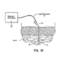
- FIGS. 6A to 6C are views showing a percutaneous lead that can form a part of a peripheral nerve stimulation system.
- FIG. 7 is a view of a package containing a peripheral nerve stimulation system.
- FIGS. 8 A/B and 9 A/B are representative leads that can form a part of a peripheral nerve stimulation system.
- FIGS. 10A and 10B are schematic anatomic views of a system for applying peripheral nerve stimulation to a femoral nerve.
- FIGS. 11A and 11B are schematic anatomic views of a system for applying peripheral nerve stimulation to a sciatic/tibial nerve.
- FIGS. 12A and 12B are schematic sectional anatomic views of systems for applying peripheral nerve stimulation to a femoral nerve and a sciatic/tibial nerve.
- FIGS. 13A , 13 B, and 13 C are schematic sectional anatomic views of a system for applying peripheral nerve stimulation along a sciatic/tibial nerve.
- FIG. 14 is a frontal view showing the peripheral nerve stimulation system and TKA incision.
- FIGS. 15A , 15 B, 15 C, and 15 D are idealized, diagrammatic view showing peripheral nerve stimulation systems.
- FIG. 16 is a view of the areas of pain and paresthesia on a diagram of the body.
- Any elements described herein as singular can be pluralized (i.e., anything described as “one” can be more than one).
- Any species element of a genus element can have the characteristics or elements of any other species element of that genus.
- the described configurations, elements or complete assemblies and methods and their elements for carrying out the invention, and variations of aspects of the invention can be combined and modified with each other in any combination.
- the peripheral nervous system consists of nerve fibers and cell bodies outside the central nervous system (the brain and the spinal column) that conduct impulses to or away from the central nervous system.
- the peripheral nervous system is made up of nerves (called spinal nerves) that connect the central nervous system with peripheral structures.
- the spinal nerves of the peripheral nervous system arise from the spinal column and exit through intervertebral foramina in the vertebral column (spine).
- the afferent, or sensory, fibers of the peripheral nervous system convey neural impulses to the central nervous system from the sense organs (e.g., the eyes) and from sensory receptors in various parts of the body (e.g., the skin, muscles, etc.).
- the efferent, or motor, fibers convey neural impulses from the central nervous system to the effector organs (muscles and glands).
- the somatic nervous system is the part of the peripheral nervous system associated with the voluntary control of body movements through the action of skeletal muscles, and with reception of external stimuli, which helps keep the body in touch with its surroundings (e.g., touch, hearing, and sight).
- the system includes all the neurons connected with skeletal muscles, skin and sense organs.
- the somatic nervous system consists of efferent nerves responsible for sending central nervous signals for muscle contraction.
- a somatic nerve is a nerve of the somatic nervous system.
- a typical spinal nerve arises from the spinal cord by rootlets which converge to form two nerve roots, the dorsal (sensory) root and the ventral (motor) root.
- the dorsal and ventral roots unite into a mixed nerve trunk that divides into a smaller dorsal (posterior) primary ramus and a much larger ventral (anterior) primary ramus.
- the posterior primary rami serve a column of muscles on either side of the vertebral column, and a narrow strip of overlying skin. All of the other muscle and skin is supplied by the anterior primary rami.
- the nerve roots that supply or turn into peripheral nerves can be generally categorized by the location on the spine where the roots exit the spinal cord, i.e., as generally shown in FIG. 2 , cervical (generally in the head/neck, designated C1 to C8), thoracic (generally in chest/upper back, designated T1 to T12), lumbar (generally in lower back, designated L1 to L5); and sacral (generally in the pelvis, designated S1 to S5). All peripheral nerves can be traced back (proximally toward the spinal column) to one or more of the spinal nerve roots in either the cervical, thoracic, lumbar, or sacral regions of the spine.
- the neural impulses comprising pain felt in a given muscle or cutaneous region of the body pass through spinal nerves and (usually) one or more nerve plexuses.
- the spinal nerves begin as roots at the spine, and can form trunks that divide by divisions or cords into branches that innervate skin and muscles.
- the sacral plexus provides motor and sensory nerves for the posterior thigh, most of the lower leg, and the entire foot.
- the sciatic nerve (also known as the ischiatic nerve) arises from the sacral plexus. It begins in the lower back and runs through the buttock and down the lower limb. The sciatic nerve supplies nearly the whole of the skin of the leg, the muscles of the back of the thigh, and those of the leg and foot. It is derived from spinal nerves L4 through S3. It contains fibers from both the anterior and posterior divisions of the lumbosacral plexus.
- the nerve gives off articular and muscular branches.
- the articular branches (rami articulares) arise from the upper part of the nerve and supply the hip-joint, perforating the posterior part of its capsule; they are sometimes derived from the sacral plexus.
- the muscular branches (rami musculares) innervate the following muscles of the lower limb: biceps femoris, semitendinosus, semimembranosus, and adductor magnus.
- the nerve to the short head of the biceps femoris comes from the common peroneal part of the sciatic, while the other muscular branches arise from the tibial portion, as may be seen in those cases where there is a high division of the sciatic nerve.
- the muscular branch of the sciatic nerve eventually gives off the tibial nerve (shown in FIG. 1A ) and common peroneal nerve (also shown in FIG. 1A ), which innervates the muscles of the (lower) leg.
- the tibial nerve innervates the gastrocnemius, popliteus, soleus and plantaris muscles and the knee joint. It also goes on to innervate all muscles of the foot except the extensor digitorum brevis (which is innervated by the peroneal nerve).
- the lumbar plexus (see FIG. 3 ) provides motor, sensory, and autonomic fibers to gluteal and inguinal regions and to the lower extremities.
- the gluteal muscles are the three muscles that make up the buttocks: the gluteus maximus muscle, gluteus maxims muscle and gluteus minimus muscle.
- the inguinal region is situated in the groin or in either of the lowest lateral regions of the abdomen.
- the iliohypogastric nerve (see FIG. 3 ) runs anterior to the psoas major on its proximal lateral border to run laterally and obliquely on the anterior side of quadratus lumborum. Lateral to this muscle, it pierces the transversus abdominis to run above the iliac crest between that muscle and abdominal internal oblique. It gives off several motor branches to these muscles and a sensory branch to the skin of the lateral hip. Its terminal branch then runs parallel to the inguinal ligament to exit the aponeurosis of the abdominal external oblique above the external inguinal ring where it supplies the skin above the inguinal ligament (i.e. the hypogastric region) with the anterior cutaneous branch.
- the ilioinguinal nerve (see FIG. 3 ) closely follows the iliohypogastric nerve on the quadratus lumborum, but then passes below it to run at the level of the iliac crest. It pierces the lateral abdominal wall and runs medially at the level of the inguinal ligament where it supplies motor branches to both transversus abdominis and sensory branches through the external inguinal ring to the skin over the pubic symphysis and the lateral aspect of the labia majora or scrotum.
- the lateral cutaneous femoral nerve (see FIG. 3 ) pierces psoas major on its lateral side and runs obliquely downward below the iliac fascia. Medial to the anterior superior iliac spine it leaves the pelvic area through the lateral muscular lacuna. In the thigh it briefly passes under the fascia lata before it breaches the fascia and supplies the skin of the anterior thigh.
- the obturator nerve leaves the lumbar plexus and descends behind psoas major on it medial side, then follows the linea terminalis and exits through the obturator canal.
- it sends motor branches to obturator externus before dividing into an anterior and a posterior branch, both of which continue distally.
- These branches are separated by adductor brevis and supply all thigh adductors with motor innervation: pectineus, adductor longus, adductor brevis, adductor magnus, adductor minimus, and gracilis.
- the anterior branch contributes a terminal, sensory branch which passes along the anterior border of gracilis and supplies the skin on the medial, distal part of the thigh.
- the femoral nerve (see FIG. 3 and also FIG. 10A ) is the largest and longest nerve of the lumbar plexus. It gives motor innervation to iliopsoas, pectineus, sartorius, and quadriceps femoris; and sensory innervation to the anterior thigh, posterior lower leg, and hindfoot. It runs in a groove between psoas major and iliacus giving off branches to both muscles. In the thigh it divides into numerous sensory and muscular branches and the saphenous nerve, its long sensory terminal branch which continues down to the foot.
- the femoral nerve has anterior branches (intermediate cutaneous nerve and medial cutaneous nerve) and posterior branches.
- the saphenous nerve (branch of the femoral nerve) provides cutaneous (skin) sensation in the medial leg.
- Other branches of the femoral nerve innervate structures (such as muscles, joints, and other tissues) in the thigh and around the hip and knee joints.
- branches of the femoral nerve innervate the hip joint, knee joint, and the four parts of the Quadriceps femoris (muscle): Rectus femoris (in the middle of the thigh) originates on the ilium and covers most of the other three quadriceps muscles.
- Vastus lateralis (on the outer side of the thigh) is on the lateral side of the femur.
- Vastus medialis (on the inner part thigh) is on the medial side of the femur.
- Vastus intermedius (on the top or front of the thigh) lies between vastus lateralis and vastus medialis on the front of the femur. Branches of the femoral nerve often innervate the pectineus and sartorius muscles.
- an electrical stimulation device 164 configured to treat post-operative pain, especially pain following limb joint replacement surgery.
- a limb joint replacement surgery is defined to include a shoulder, elbow, wrist, finger joint, hip, knee, ankle and toe joint, but to exclude the back, neck and head.
- the electrical stimulation device may include one or more leads 12 having one or more electrodes 14 adapted for insertion into in any tissue of the body in electrical proximity but away from nerves. This location of leads 12 may improve recruitment of targeted nerves for therapeutic purposes, such as for the treatment of pain. It is to be appreciated that the present electrical stimulation device is intended only to treat regions of pain that include any limbs or joint replacements, including arms and legs in both humans and animals.
- FIGS. 15A-15D show a peripheral nerve system and method that incorporates features of the present teachings.
- the system and method may identify a region where there is a local manifestation of pain.
- the region of pain may comprise any appropriate portion of the body, e.g., tissue, skin, bone, a joint, or muscle.
- the system and method may identify one or more spinal nerves located distant from the region where pain is manifested, through which neural impulses comprising the pain pass.
- a given spinal nerve that is identified may comprise a nerve trunk located in a nerve plexus, or a division and/or a cord of a nerve trunk, or a nerve branch, or a nerve plexus provided that it is upstream or cranial of where the nerve innervates the region affected by the pain.
- the given spinal nerve may be identified by medical professionals using textbooks of human anatomy along with their knowledge of the site and the nature of the pain or injury, as well as by physical manipulation and/or imaging, e.g., by ultrasound, fluoroscopy, or X-ray examination, of the region where pain is manifested.
- a desired criteria of the selection may include identifying the location of tissue in a therapeutically effective distance from the nerve or passage, which tissue may be accessed by placement of one or more stimulation electrodes, aided if necessary by ultrasonic or electro-location techniques.
- a therapeutically effective distance may be defined to mean the placement of a lead either in contact with, or more preferably adjacent to a nerve.
- the nerve identified may comprise a targeted peripheral nerve.
- the tissue identified may comprise the “targeted tissue.”
- the electrodes 14 of the electrical stimulation device 164 may be percutaneously inserted using percutaneous leads 12 .
- the system and method may place the one or more leads 12 (B) with its electrode 14 (B) in the targeted tissue in electrical proximity to but spaced away from the targeted peripheral nerve.
- the system and method may apply electrical stimulation through the one or more stimulation electrodes 14 (B) to electrically activate or recruit the targeted peripheral nerve that conveys the neural impulses comprising the pain to the spinal column.
- the system and method may apply electrical stimulation to peripheral nerves throughout the body.
- the peripheral nerves may comprise one or more spinal nerves in the brachial plexus, to treat pain in the shoulders (see FIG. 15C ), arms and hands (see FIG. 15D ); and/or one or more spinal nerves in the lumbar plexus, to treat pain in the thighs, knees, and calves (see FIGS. 15A and 15B ); and/or one or more spinal nerves in the sacral plexus, to treat pain in the thighs, calves, and feet (see FIGS. 15A and 15B ); and/or one or more spinal nerves in the cervical plexus, to treat pain in the shoulders (see FIG. 15C ).
- the system and method may identify and stimulate the ulnar nerve at a location upstream or cranial of where the nerve innervates the muscle or skin of the pinky finger, e.g., in the palm of the hand, forearm, and/or upper arm. If electrical stimulation activates the target peripheral nerve sufficiently at the correct intensity, then the patient will feel a comfortable tingling sensation called paresthesia in the same region as their pain, which overlaps with the region of pain and/or otherwise reduce pain.
- Evoking paresthesia in the region of pain confirms correct lead placement and indicates stimulus intensity is sufficient to reduce pain. Inserting a lead 12 percutaneously may allow the lead 12 to be placed quickly and easily. Placing the lead 12 in a peripheral location, i.e., tissue, where it is less likely to be dislodged, may address lead migration problems of spinal cord stimulation that may otherwise cause decreased paresthesia coverage, decreased pain relief, and the need for frequent patient visits for reprogramming.
- an electrode lead 12 such as a coiled fine wire electrode lead may be used because it is minimally-invasive and well suited for placement in proximity to a peripheral nerve.
- the lead may be sized and configured to withstand mechanical forces and resist migration during long-term use, particularly in flexible regions of the body, such as the shoulder, elbow, and knee.
- the electrode lead may include a fine wire electrode 14 , paddle electrode, intramuscular electrode, or general-purpose electrode, inserted via a needle introducer 30 or surgically implanted in proximity of a targeted peripheral nerve.
- the needle introducer 30 may be withdrawn (as FIGS. 6B and 6C show), leaving the electrode 14 in place.
- Stimulation may also be applied through a penetrating electrode, such as an electrode array comprised of any number (i.e., one or more) of needle-like electrodes that may be inserted into the target site.
- the lead may be placed using a needle-like introducer 30 , allowing the lead/electrode placement to be minimally invasive.
- the lead 12 may include a thin, flexible component made of a metal and/or polymer material. By “thin,” it is contemplated that the lead may not be greater than about 0.75 mm (0.030 inch) in diameter. However, the present teachings are not limited to such dimensions. Any appropriate lead 12 may be utilized.
- the lead 12 may also include one or more coiled metal wires with in an open or flexible elastomer core.
- the wire may be insulated, e.g., with a biocompatible polymer film, such as polyfluorocarbon, polyimide, or parylene.
- the lead 12 may be electrically insulated everywhere except at one (monopolar), or two (bipolar), or three (tripolar), for example, conduction locations near its distal tip.
- Each of the conduction locations may be connected to one or more conductors that may run the length of the lead and lead extension 16 (see FIG. 6C ) or a portion thereof.
- the conductor may provide electrical continuity from the conduction location through the lead 12 to an external pulse generator or stimulator 28 (see FIG. 6C ).
- the conduction location or electrode 14 may include a de-insulated area of an otherwise insulated conductor that may run the length of an entirely insulated electrode or a portion thereof.
- the de-insulated conduction region of the conductor may be formed differently, e.g., it may be wound with a different pitch, or wound with a larger or smaller diameter, or molded to a different dimension.
- the conduction location or the electrode 14 may include a separate material (e.g., metal or a conductive polymer) exposed to the body tissue to which the conductor of the wire is bonded.
- the lead 12 may be provided in a sterile package 62 (see FIG. 7 ), and may be pre-loaded in the introducer needle 30 . Alternatively, the lead may be introduced via the same needle that is used to inject anesthetic or analgesics during peripheral nerve blocks, which are often used post-limb joint replacement surgery.
- the package 62 may take various forms and the arrangement and contents of the package 62 may be as appropriate related to the use thereof. As shown in FIG. 7 , the package 62 may include a sterile, wrapped assembly.
- the package 62 may include an interior tray made from any appropriate material, e.g., from die cut cardboard, plastic sheet, or thermo-formed plastic material, which may hold the contents.
- the package 62 may also desirably include instructions for use 58 regarding using the contents of the package to carry out the lead 12 location and placement procedures, as will be described in greater detail below.
- the lead 12 may possess mechanical properties in terms of flexibility and fatigue life that provide an operating life free of mechanical and/or electrical failure, taking into account the dynamics of the surrounding tissue (i.e., stretching, bending, pushing, pulling, crushing, etc.).
- the material of the electrode 14 may discourage the in-growth of connective tissue along its length or an applicable portion thereof, so as not to inhibit its withdrawal at the end of its use. However, it may be desirable to encourage the in-growth of connective tissue at the distal tip of the electrode 14 , to enhance its anchoring in tissue.
- Embodiments of the lead 12 shown in FIG. 12A may include a minimally invasive coiled fine wire lead 12 and electrode 14 .
- the electrode 14 may also include, at its distal tip, an anchoring element 48 .
- the anchoring element 48 may take the form of a simple barb or bend (see also FIG. 6C ).
- the anchoring element 48 may be sized and configured so that, when in contact with tissue, it takes purchase in tissue, to resist dislodgement or migration of the electrode 14 out of the correct location in the surrounding tissue. Desirably, the anchoring element 48 may be prevented from fully engaging body tissue until after the electrode 14 has been correctly located and deployed.
- the electrode lead 12 shown in FIGS. 9A and 9B may also include, at or near its distal tip or region, one or more anchoring element(s) 70 .
- the anchoring element 70 may take the form of an array of shovel-like paddles or scallops 76 proximal to the proximal-most electrode 14 (although a paddle 76 or paddles may also be proximal to the distal most electrode 14 , or may also be distal to the distal most electrode 14 ).
- the paddles 76 as shown may be sized and configured so they will not cut or score the surrounding tissue.
- the anchoring element 70 may be sized and configured so that, when in contact with tissue, it takes purchase in tissue, to resist dislodgement or migration of the electrode out of the correct location in the surrounding tissue (e.g., muscle 54 ).
- the anchoring element 70 may be prevented from fully engaging body tissue until after the electrode 14 has been deployed.
- the electrode 14 may not be deployed until after it has been correctly located during the implantation (lead placement) process, as previously described.
- the lead 12 may include one or more ink markings 74 , 75 (shown in FIG. 9A ) to aid the clinician in its proper placement.
- stimulation may be applied through any type of nerve cuff (spiral, helical, cylindrical, book, flat interface nerve electrode (FINE), slowly closing FINE, etc.), paddle (or paddle-style) electrode lead, cylindrical electrode lead, echogenic needle (i.e., visible under ultrasound) and/or other lead that is surgically or percutaneously placed within tissue at the target site.
- nerve cuff spiral, helical, cylindrical, book, flat interface nerve electrode (FINE), slowly closing FINE, etc.
- paddle or paddle-style electrode lead
- cylindrical electrode lead or echogenic needle (i.e., visible under ultrasound) and/or other lead that is surgically or percutaneously placed within tissue at the target site.
- the lead 12 may exit through the skin and connect with one or more external stimulators 28 (this approach is shown in FIG. 6C ). Further, the lead 12 may be connected as needed to internal and external coils for RF (Radio Frequency) wireless telemetry communications or an inductively coupled telemetry to control the implanted pulse generator 28 .
- the implanted pulse generator 28 may be located some distance (remote) from the electrode 14 , or an implanted pulse generator may be integrated with an electrode(s) (not shown), eliminating the need to route the lead subcutaneously to the implanted pulse generator.
- the introducer 30 may be insulated along the length of the shaft, except for those areas that correspond with the exposed conduction surfaces of the electrode 14 housed inside the introducer 30 . These surfaces on the outside of the introducer 30 may be electrically isolated from each other and from the shaft of the introducer 30 . These surfaces may be electrically connected to a connector 64 at the end of the introducer body (see FIG. 6A ). This may allow connection to an external stimulator 28 (shown in FIG. 6A ) during the implantation process. Applying stimulating current through the outside surfaces of the introducer 30 may provide a close approximation to the response that the electrode 14 will provide when it is deployed at the current location of the introducer 30 .
- the introducer 30 may be sized and configured to be bent by hand prior to its insertion through the skin. This may allow the physician to place the lead 12 in a location that is not in an unobstructed straight line with the insertion site.
- the construction and materials of the introducer 30 may allow bending without interfering with the deployment of the lead 12 and withdrawal of the introducer 30 , leaving the lead 12 in the tissue.
- test stimulation may be delivered through needle electrodes. Needle electrodes may be used because they may be easily repositioned until the optimal location to deliver stimulation is determined. A test needle may be used to generate paresthesia.
- At least one lead(s) may be placed in tissue near a targeted peripheral nerve.
- the lead may be inserted via the introducer 30 in any appropriate manner, which may be similar in size and shape to a hypodermic needle.
- the introducer 30 may be any size. By way of a non-limiting example, the introducer 30 may range in size from 17 gauge to 26 gauge.
- the insertion site may be cleaned with a disinfectant (e.g., Betadine, 2% Chlorhexidine/80% alcohol, 10% povidone-iodine, or similar agent).
- a local anesthetic(s) may be administered topically and/or subcutaneously to the area in which the electrode and/or introducer will be inserted.
- the position of the electrodes may be checked by imaging techniques, such as ultrasound, fluoroscopy, or X-rays.
- imaging techniques such as ultrasound, fluoroscopy, or X-rays.
- the portion of the leads which exit the skin may be secured to the skin using covering bandages and/or adhesives.
- Electrical stimulation may be applied to the targeted peripheral nerve during and after placement of the electrode. This may be used to determine whether stimulation of the targeted peripheral nerve can generate comfortable sensations or paresthesia that overlap with the region of pain and/or reduce pain.
- the lead 12 may be percutaneously placed near the targeted peripheral nerve and exit at a skin puncture site 16 .
- a trial or screening test may be conducted in any appropriate clinical setting (e.g., an office of a clinician, a laboratory, a procedure room, an operating room, an intensive care unit, an acute rehabilitation facility, a subacute rehabilitation facility, etc.).
- the lead 12 may be coupled to an external pulse generator 28 and temporary percutaneous and/or surface return electrodes, to confirm paresthesia coverage and/or pain relief of the painful areas.
- the patient may proceed to treatment with an external pulse generator 28 (as shown in FIG. 6C ) and temporary percutaneous and/or surface return electrodes.
- the treatment period may range from minutes to hours to days to weeks to months. By way of a non-limiting example, the treatment period may be between approximately three and 21 days.
- a fully implanted pulse generator may be used if an external stimulator is considered too cumbersome for the patient.
- Regulated current may be used as a type of stimulation, but other type(s) of stimulation (e.g., non-regulated current such as voltage-regulated) may also be used.
- Multiple types of electrodes may be used, such as surface, percutaneous, and/or implantable electrodes.
- the surface electrodes may be a standard shape or they may be modified as appropriate to fit the contour of the skin.
- the surface electrode(s) may serve as the anode(s) (or return electrode(s)), but the surface electrode(s) may be used as the cathode(s) (active electrode(s)) if necessary.
- the location of the electrode(s) may not be critical and may be positioned anywhere in the general vicinity, provided that the current path does not cross parts of the body (e.g., the heart), through which stimulation could be harmful.
- the electrode lead may be placed via multiple types of approaches.
- the approach may be either a posterior (shown in FIG. 10A ) or an anterior approach (shown in FIG. 11A ). This may be similar to those used for regional anesthesia of the same targeted peripheral nerve, except that the approach may be used for placement through an introducer of stimulation lead(s) in electrical proximity to but spaced away from a peripheral nerve, and not for regional anesthesia.
- the approach to nerves of the lumbar plexus or sacral plexus may not involve the application of anesthesia to the nerve, and, when the introducer is withdrawn, the lead(s) may be left behind to desired stimulation of the target peripheral nerve.
- the introducer(s) 30 and/or lead(s) 12 may be directed towards the sciatic nerve using a posterior approach, such as the transgluteal approach or subgluteal approach, which are both well described and commonly used in regional anesthesiology.
- This approach may allow lead placement near a targeted peripheral nerve with a simple, quick (e.g., less than 10 minutes) procedure.
- the landmarks for the transgluteal approach may include the greater trochanter and the posterior superior iliac spine.
- the introducer 30 may be inserted distal (e.g., approximately 2 cm to 6 cm, preferably 4 cm, in a preferred embodiment) to the midpoint between the greater trochanter and the posterior iliac spine.
- the patient may be in a lateral decubitus position and tilted slightly forward.
- the landmarks for the subgluteal approach may include the greater trochanter and the ischial tuberosity.
- the introducer may be inserted distal (e.g., approximately 2 cm to 6 cm, preferably 4 cm, in the preferred embodiment) to the midpoint between the greater trochanter and the ischial tuberosity.
- percutaneous leads 12 may be directed towards the femoral nerve using an anterior approach.
- the landmarks may include the inguinal ligament, inguinal crease, and femoral artery.
- the subject may be in the supine position with ipsilateral extremity slightly (approximately 10 to 20 degrees) abducted.
- the introducer may be inserted near the femoral crease but below the inguinal crease and approximately 1 cm lateral to the pulse of the femoral artery.
- tissue such as the buttocks, surrounding the target nerves may vary across subjects, and the approach may be modified as appropriate to accommodate various body sizes and shapes to access the target nerve.
- Introducer placement may be guided by the individual's report of stimulus-evoked sensations (paresthesia) as the introducer is placed during test stimulation.
- paresthesia stimulus-evoked sensations
- more than a single lead 12 may be placed around a given peripheral nerve, using either an anterior approach (e.g., femoral nerve) or a posterior approach (e.g., sciatic nerve).
- an anterior approach e.g., femoral nerve
- a posterior approach e.g., sciatic nerve
- one or more leads 12 may be placed at different superior-inferior positions along a peripheral nerve and/or along different peripheral nerves.
- the lead 12 may be coupled to an external pulse generator 28 worn, e.g., on a belt, for a temporary stimulation regime.
- the lead 12 may be covered with a bandage 50 , and a surface electrode 54 may serve as a return electrode.
- the external/percutaneous system shown in FIGS. 10B and 10B may be replaced by an implanted system using an implanted pulse generator 60 and tunneled leads 62 .
- the case of the implanted pulse generator 60 A may include the return electrode.
- Control of the stimulator and stimulation parameters may be provided by one or more external controllers.
- a controller may be integrated with the external stimulator.
- the implanted pulse generator external controller i.e., clinical programmer
- the implanted pulse generator external controller may be a remote unit that uses RF (Radio Frequency) wireless telemetry communications (rather than an inductively coupled telemetry) to control the implanted pulse generator.
- the external or implantable pulse generator may use passive charge recovery to generate the stimulation waveform, regulated voltage (e.g., 10 mV to 20 V), and/or regulated current (e.g., about 10 mA to about 50 mA).
- Passive charge recovery may be one method of generating a biphasic, charge-balanced pulse as desired for tissue stimulation without severe side effects due to a DC component of the current.
- the neurostimulation pulse may by monophasic (anodic or cathodic), biphasic, and/or multi-phasic.
- the pulse may be symmetrical or asymmetrical. Its shape may be rectangular or exponential or a combination of rectangular and exponential waveforms.
- the pulse width of each phase may range between e.g., about 0.1 ⁇ sec. to about 1.0 sec., as non-limiting examples.
- Pulses may be applied in continuous or intermittent trains (i.e., the stimulus frequency changes as a function of time).
- the on/off duty cycle of pulses may be symmetrical or asymmetrical, and the duty cycle may be regular and repeatable from one intermittent burst to the next or the duty cycle of each set of bursts may vary in a random (or pseudo random) fashion. Varying the stimulus frequency and/or duty cycle may assist in warding off habituation because of the stimulus modulation.
- the stimulating frequency may range from e.g., about 1 Hz to about 300 Hz.
- the frequency of stimulation may be constant or varying. In the case of applying stimulation with varying frequencies, the frequencies may vary in a consistent and repeatable pattern or in a random (or pseudo random) fashion or a combination of repeatable and random patterns.
- the stimulator may be set to an intensity (e.g., 1-2 mA (or 0.1-40 mA, or 0.01-200 mA), 100-300 us (or 40-1000 us, or 1-10,000 us)) sufficient to activate the targeted nerve at some distance X 1 (e.g., 1 mm) away (from the targeted peripheral nerve). If the stimulus intensity is too great, it may generate muscle twitch(es) or contraction(s) sufficient to disrupt correct placement of the lead. If stimulus intensity is too low, the lead may be advanced too close to the targeted peripheral nerve (beyond the optimal position), possibly leading to incorrect guidance, nerve damage, mechanically evoked sensation (e.g., pain and/or paresthesia) and/or muscle contraction (i.e.
- the lead when the lead touches the peripheral nerve), inability to activate the target nerve fiber(s) without activating non-target nerve fiber(s), improper placement, and/or improper anchoring of the lead (e.g., the lead may be too close to the nerve and no longer able to anchor appropriately in the muscle tissue).
- Patient sensation may instead be used to indicate lead location relative to the targeted peripheral nerve as indicator(s) of lead placement (distance from the peripheral nerve to electrode contact).
- Any combination of stimulus parameters that evoke sensation(s) may be used.
- the stimulation parameters may include, but are not limited to frequency, pulse duration, amplitude, duty cycle, patterns of stimulus pulses, and waveform shapes.
- Some stimulus parameters may evoke a more desirable response (e.g., more comfortable sensation, or a sensation that may be correlated with or specific to the specific target nerve fiber(s) within the targeted peripheral nerve.
- higher frequencies e.g., 100 Hz or 12 Hz
- the lead 12 While stimulation is being applied, the lead 12 (non-limiting examples of the lead could include a single or multi-contact electrode that is designed for temporary (percutaneous) or long-term (implant) use or a needle electrode (used for in-office testing only)) may be advanced (e.g., slowly advanced) towards the targeted peripheral nerve until the desired indicator response (e.g., patient sensation, and/or pain relief) is obtained.
- the desired indicator response e.g., patient sensation, and/or pain relief
- the intensity may then be decreased (e.g., gradually decreased) as the lead 12 is advanced (e.g., advanced slowly) closer to the targeted nerve until the desired indicator response(s) may be obtained at smaller intensity(ies) within a target range (e.g., 0.1-1.0 mA (or 0.09-39 mA, or 0.009-199 mA), 100-300 us (or 40-1000 us, or 1-10,000 us)).
- a target range e.g., 0.1-1.0 mA (or 0.09-39 mA, or 0.009-199 mA), 100-300 us (or 40-1000 us, or 1-10,000 us).
- the electrode 14 may be placed and anchored at about 1 millimeter to about 100 millimeters spaced from the target nerve, more preferably from about 1 millimeter to about 50 millimeters spaced from the target nerve.
- the electrode may touch the nerve, however, this is sub-optimal.
- the electrode spacing from a targeted nerve may depend on various factors, and similar stimulation settings may invoke different responses even if spaced at similar distances.
- electrode spacing from the nerve may be about 10 to about 20 millimeters for one target nerve at a given stimulation intensity while the spacing may be about 20 to about 40 millimeters for a second target nerve at the same stimulation intensity.
- the lead may be located in a non-optimal location (e.g., too close to the target nerve(s)). In such situations, therefore, the clinician may adjust the lead location until the appropriate responses are achieved from the patient.
- the stimulus intensities may be a function of many variables.
- the stimulus intensities set forth herein are meant to serve as non-limiting examples only, and may need to be scaled accordingly.
- the stimulus intensities may need to change appropriately.
- the intensities were calculated for a lead with an electrode surface area of approximately 20 mm 2 , then they may need to be scaled down accordingly to be used with a lead with an electrode surface area of 0.2 mm 2 because a decrease in stimulating surface area may increase the current density, increasing the potential to activate excitable tissue (e.g., target and non-target nerve(s) and/or fiber(s)).
- the intensities may need to be scaled up accordingly to be used with a lead with an electrode surface area of 20 mm 2 .
- stimulus intensities may need to be scaled to account for variations in electrode shape or geometry (between or among electrodes) to compensate for any resulting variations in current density.
- the electrode contact surface area may be 0.1-20 mm 2 , 0.01-40 mm 2 , or 0.001-200 mm 2 .
- the electrode contact configuration may include one or more of the following characteristics: cylindrical, conical, spherical, hemispherical, circular, triangular, trapezoidal, raised (or elevated), depressed (or recessed), flat, and/or borders and/or contours that are continuous, intermittent (or interrupted), and/or undulating.
- Stimulus intensities may need to be scaled to account for biological factors, including but not limited to patient body size, weight, mass, habitus, age, and/or neurological condition(s).
- patients that are older have a higher body-mass index (BMI), and/or neuropathy (e.g., due to diabetes) may need to have stimulus intensities scaled higher (or lower) accordingly.
- BMI body-mass index
- neuropathy e.g., due to diabetes
- stimulation may be unable to evoke the desired response (e.g., comfortable sensation(s) (or paresthesia(s)), and/or pain relief) in the desired region(s) at the desired stimulus intensity(ies).
- stimulation may be unable to evoke the desired response(s) (e.g., comfortable sensation(s) (or paresthesia(s)), and/or pain relief) in the desired region(s) at the desired stimulus intensity(ies) without evoking undesirable response(s) (e.g., unwanted and/or painful sensation(s) (or paresthesia(s)), increase in pain, and/or generation of additional pain in related or unrelated area(s)).
- alternative stimulus waveforms and/or combinations of leads and/or electrode contacts may be used.
- alternative stimulus waveforms may include the use of a pre-pulse to increase the excitability of the target fiber(s) and/or decrease the excitability of the non-target fiber(s).
- This stimulation may be used pre-operatively or intra-operatively to limit or prevent post-operative pain.
- TKA total knee arthroplasty
- the knee is innervated by the femoral, lateral femoral cutaneous, obturator, and the sciatic nerves. Anesthetic block of these nerves individually or as a group may reduce acute pain following a TKA.
- the method may include:
- the lead may be of any appropriate configuration, such as by way of a non-limiting example, a single fine wire with one lead to target each nerve.
- a surface stimulation return electrode in proximity to the lead insertion site.
- the surface electrode may be placed adjacent to the insertion site. Its position is not critical to the therapy and it may be moved throughout the therapy to reduce the risk of skin irritation, but care should be taken to place the electrode distant from the surgical incision to generally avoid infection.
- Test stimulation may be delivered using a current-regulated pulse generator, for example.
- the external pulse generator 28 may be a battery-powered stimulator, for example.
- the electrode may be located at an area to generate maximal paresthesia coverage of the religion of pain, as defined by a patient shaded diagram of the body. During stimulation, the patient is asked to estimate how much of the area of pain is covered by paresthesia. For example, as in FIG. 16 , the shaded regions indicate where the patient experiences paresthesia during stimulation.
- a bandage may also be used to secure the external portion of the lead 12 (or an extension cable may be used to couple the lead 12 to the external pulse generator) to the skin. It is expected the length of time to place the lead 12 to be less than 10 minutes, although the process may be shorter or longer.
- the external pulse generator 28 may be programmed to 100 Hz, 15 ⁇ s with amplitude sufficient to generate maximum paresthesia coverage.
- the parameter may include 100% duty cycle (for both femoral and sciatic) for 24 hours per day.
- the stimulation may be on for the duration of the acute or subacute pain of the patient. Patients may receive the stimulation therapy for a predetermined time, such as by way of a non-limiting example, two to four weeks.
- stimulation intensity may need to be increased slightly during the process due to causes such as habituation or the subject becoming accustomed to sensation.
- the need for increased intensity may be unlikely and usually only occurs after several days to weeks to months as the tissue encapsulates and the subject accommodates to stimulation. It is to be appreciated that the need for increased intensity may happen at any time, which may be due to either lead migration or habituation, but may also be due reasons ranging from nerve damage to plasticity/reorganization in the central nervous system.
- a sterile test needle may be used to deliver stimulation and determine the desired site of insertion.
- a second percutaneous lead (not shown) may be placed to stimulate the nerves that are not activated by the first lead 12 , i.e., the nerves innervating the region of post-operative pain.
- femoral and sciatic nerves or they may also stimulate the lumbar plexus to target the femoral, obturator, and/or lateral femoral cutaneous nerves.
- An alternative embodiment may include using a needle electrode/lead and placing it during insertion of needles used during anesthetic peripheral nerve block.
- the pulse trains may be varied, as varied pulse shapes may improve selectivity of activation of paresthesia-fibers versus pain fibers.
- Percutaneous electrical stimulation of nerves may provide some pain relief as anesthetic block without many of its drawbacks. This therapy may be provided as a temporary therapy or as a permanent implant. Acute pain relief may allow patients to recover sufficiently enabling them to begin rehabilitation, which is critical to regaining normal function and natural pain relief. It is generally thought that if 50% paresthesia coverage is achieved, then there is a 70% success rate. Oftentimes after the stimulation therapy, the pain will never return to the patient.
- TKA is discussed herein, it is to be understood that the systems and methods may be employed to condition a body before or after any limb joint replacement surgery. While stimulation of the femoral and/or sciatic nerves should generally provide relief of pain following a limb joint replacement surgery of the leg, more distal peripheral nerves may be targets for surgeries related to distal portions of the leg (foot, ankle surgery, e.g.). For arm/hand limb joint replacement surgery-related pain, nerves near the brachial plexus, near or below the shoulder, elbow, or wrist may be targeted.
- the lead In peripheral nerve stimulation, the lead may be placed in a tissue by which the targeted nerve passes, but stimulation actually relieves pain that is felt distal (downstream) from where the lead is placed.
- the lead In peripheral nerve stimulation, the lead may be placed in a tissue that is conveniently located near a nerve trunk that passes by the lead on the way to or from the painful area. The key is that the lead may be placed in a tissue that is not the target (painful) tissue, but rather a tissue that is located away from the painful region, which is a safer and more convenient location to place the lead.
- Peripheral nerve stimulation may be easily used by clinicians, including, but to limited to, general surgeons, orthopedic surgeons, and anesthesiologists, who are used to placing needles deeper in the tissue near peripheral nerves.
- clinicians including, but to limited to, general surgeons, orthopedic surgeons, and anesthesiologists, who are used to placing needles deeper in the tissue near peripheral nerves.
- anesthesiologists are accustomed to placing needles distant from the areas of pain to numb the areas of pain.
- Anesthesiologists often already use ultrasound and the electro-location techniques that may be needed to place leads to access peripheral nerves. This may result in the system and method to be used in practice with little or no training.
- Peripheral nerve stimulation may provide stimulation-generated paresthesia (that ideally overlap with the area of pain) but may not require evoking a muscle contraction to place the lead correctly.
- the target regions in which pain is felt and which are targeted for generation of paresthesia may not be the same region in which the lead is placed. This may be useful because physicians (e.g., anesthesiologists) who will typically be placing the lead are accustomed to using paresthesia (sensory feedback description of from the patient) to guide lead placement and tuning of stimulation parameters.
- Imaging may be used to improve lead placement near peripheral nerves.
- Ultrasound may improve lead placement in the form of increasing the total speed of the procedure.
- ultrasound may shorten the procedure's duration by locating the lead in a more optimal location. Doing so may: improve recruitment of the target fibers in the target nerve and minimize recruitment of non-target fibers in either the target nerve and/or in non-target nerve(s); and minimize risk and/or damage to the patient during placement of the lead by avoiding blood vessels, organs, bones, ligaments, tendons, lymphatic vessels, &/or other structures that may be damaged.
- One reason that imaging may be useful is that some peripheral nerves are (but do not have to be) located relatively deeply.
- fluoroscopy may be desirably avoided, thus lessening the cost of the procedure and the risk of radiation exposure.
- the patient may not need to give verbal, written, or other type of feedback or indication of what they feel as the lead is being advanced towards the peripheral nerve if imaging is used to guide lead placement.
- any known method for non-verbal communication can be used, including those used by anesthesiologists. This allows for the system to be placed in an unconscious patient, e.g., in a sedated patient or intra-operatively.
- patient feedback during lead advancement may improve lead placement in some patients.
- the patient may indicate sensations during tuning of stimulus intensity.
- those sensations reported by the patient may include first sensation (minimum stimulus intensity that evokes a sensation), level of comfort, maximum tolerable sensation, pain, qualities or descriptions of the sensations.
- the optimal coverage would be a region that is likely to be painful following the limb joint replacement surgery (e.g., in the case of a TKA, both the front and back of the knee).
- the region in which the patient perceives stimulation-induced sensations or paresthesia may be an important indicator of the potential success of the therapy. This may help screen potential candidates and may help determine the appropriate stimulation parameters (including but not limited to lead location). Further, such parameters may be adjusted so that the region in which paresthesia is perceived overlaps with the region of pain.
- the level of pain or change in the intensity of pain during or due to stimulation may be used to adjust stimulation parameters (including but not limited to lead location). For example, if a patient is experiencing “very high” pain before stimulation, no sensory or motor responses are evoked and during stimulation, if the pain decreases to “low”, the system would be considered satisfactory in the patient.
Abstract
Description
Claims (20)
Priority Applications (5)
| Application Number | Priority Date | Filing Date | Title |
|---|---|---|---|
| US13/791,710 US8965516B2 (en) | 2012-03-08 | 2013-03-08 | System and method for treatment of pain related to limb joint replacement surgery |
| US14/547,493 US9555245B2 (en) | 2012-03-08 | 2014-11-19 | System and method for treatment of pain related to limb joint replacement surgery |
| US15/419,038 US20170173329A1 (en) | 2012-03-08 | 2017-01-30 | System and method for treatment of pain related to limb joint replacement surgery |
| US16/391,362 US11116971B2 (en) | 2012-03-08 | 2019-04-23 | System and method for treatment of pain related to limb joint replacement surgery |
| US17/472,753 US20210402181A1 (en) | 2012-03-08 | 2021-09-13 | System and method for treatment of pain related to limb joint replacement surgery |
Applications Claiming Priority (2)
| Application Number | Priority Date | Filing Date | Title |
|---|---|---|---|
| US201261608106P | 2012-03-08 | 2012-03-08 | |
| US13/791,710 US8965516B2 (en) | 2012-03-08 | 2013-03-08 | System and method for treatment of pain related to limb joint replacement surgery |
Related Child Applications (1)
| Application Number | Title | Priority Date | Filing Date |
|---|---|---|---|
| US14/547,493 Continuation US9555245B2 (en) | 2012-03-08 | 2014-11-19 | System and method for treatment of pain related to limb joint replacement surgery |
Publications (2)
| Publication Number | Publication Date |
|---|---|
| US20130253605A1 US20130253605A1 (en) | 2013-09-26 |
| US8965516B2 true US8965516B2 (en) | 2015-02-24 |
Family
ID=49117414
Family Applications (5)
| Application Number | Title | Priority Date | Filing Date |
|---|---|---|---|
| US13/791,710 Active US8965516B2 (en) | 2012-03-08 | 2013-03-08 | System and method for treatment of pain related to limb joint replacement surgery |
| US14/547,493 Active US9555245B2 (en) | 2012-03-08 | 2014-11-19 | System and method for treatment of pain related to limb joint replacement surgery |
| US15/419,038 Abandoned US20170173329A1 (en) | 2012-03-08 | 2017-01-30 | System and method for treatment of pain related to limb joint replacement surgery |
| US16/391,362 Active 2033-08-11 US11116971B2 (en) | 2012-03-08 | 2019-04-23 | System and method for treatment of pain related to limb joint replacement surgery |
| US17/472,753 Pending US20210402181A1 (en) | 2012-03-08 | 2021-09-13 | System and method for treatment of pain related to limb joint replacement surgery |
Family Applications After (4)
| Application Number | Title | Priority Date | Filing Date |
|---|---|---|---|
| US14/547,493 Active US9555245B2 (en) | 2012-03-08 | 2014-11-19 | System and method for treatment of pain related to limb joint replacement surgery |
| US15/419,038 Abandoned US20170173329A1 (en) | 2012-03-08 | 2017-01-30 | System and method for treatment of pain related to limb joint replacement surgery |
| US16/391,362 Active 2033-08-11 US11116971B2 (en) | 2012-03-08 | 2019-04-23 | System and method for treatment of pain related to limb joint replacement surgery |
| US17/472,753 Pending US20210402181A1 (en) | 2012-03-08 | 2021-09-13 | System and method for treatment of pain related to limb joint replacement surgery |
Country Status (5)
| Country | Link |
|---|---|
| US (5) | US8965516B2 (en) |
| EP (1) | EP2822641B1 (en) |
| AU (1) | AU2013229854B2 (en) |
| CA (1) | CA2866609C (en) |
| WO (1) | WO2013134725A1 (en) |
Cited By (33)
| Publication number | Priority date | Publication date | Assignee | Title |
|---|---|---|---|---|
| US20150073496A1 (en) * | 2012-03-08 | 2015-03-12 | Spr Therapeutics, Llc | System and method for treatment of pain related to limb joint replacement surgery |
| US9474906B2 (en) | 2007-03-09 | 2016-10-25 | Mainstay Medical Limited | Systems and methods for restoring muscle function to the lumbar spine |
| US9861811B2 (en) | 2010-03-11 | 2018-01-09 | Mainstay Medical Limited | Electrical stimulator for treatment of back pain and methods of use |
| US9950159B2 (en) | 2013-10-23 | 2018-04-24 | Mainstay Medical Limited | Systems and methods for restoring muscle function to the lumbar spine and kits for implanting the same |
| US9981122B2 (en) | 2012-06-13 | 2018-05-29 | Mainstay Medical Limited | Systems and methods for implanting electrode leads for use with implantable neuromuscular electrical stimulator |
| US9999763B2 (en) | 2012-06-13 | 2018-06-19 | Mainstay Medical Limited | Apparatus and methods for anchoring electrode leads adjacent to nervous tissue |
| US10076663B2 (en) | 2010-11-11 | 2018-09-18 | Spr Therapeutics, Inc. | Systems and methods for the treatment of pain through neural fiber stimulation |
| US10195419B2 (en) | 2012-06-13 | 2019-02-05 | Mainstay Medical Limited | Electrode leads for use with implantable neuromuscular electrical stimulator |
| US10327810B2 (en) | 2016-07-05 | 2019-06-25 | Mainstay Medical Limited | Systems and methods for enhanced implantation of electrode leads between tissue layers |
| US10471257B2 (en) | 2016-05-19 | 2019-11-12 | The Cleveland Clinic Foundation | Implantable temporary nerve conduction blocking method and system |
| US10471268B2 (en) | 2014-10-16 | 2019-11-12 | Mainstay Medical Limited | Systems and methods for monitoring muscle rehabilitation |
| US10589089B2 (en) | 2017-10-25 | 2020-03-17 | Epineuron Technologies Inc. | Systems and methods for delivering neuroregenerative therapy |
| US10722715B2 (en) | 2010-11-11 | 2020-07-28 | Spr Therapeutics, Inc. | Systems and methods for the treatment of pain through neural fiber stimulation |
| US10780270B2 (en) | 2018-03-15 | 2020-09-22 | Avent, Inc. | System and method to percutaneously block painful sensations |
| US10857361B2 (en) | 2010-11-11 | 2020-12-08 | Spr Therapeutics, Inc. | Systems and methods for the treatment of pain through neural fiber stimulation |
| US10925637B2 (en) | 2010-03-11 | 2021-02-23 | Mainstay Medical Limited | Methods of implanting electrode leads for use with implantable neuromuscular electrical stimulator |
| US11013922B2 (en) | 2014-09-26 | 2021-05-25 | Duke University | Systems and methods for spinal cord stimulation |
| US11103706B2 (en) | 2007-03-09 | 2021-08-31 | Mainstay Medical Limited | Systems and methods for enhancing function of spine stabilization muscles associated with a spine surgery intervention |
| US11116974B2 (en) | 2017-03-27 | 2021-09-14 | Biotronik Se & Co. Kg | Device and method for multi-modality spinal cord stimulation therapy |
| US11247045B2 (en) | 2017-10-25 | 2022-02-15 | Epineuron Technologies Inc. | Systems and methods for delivering neuroregenerative therapy |
| US11247043B2 (en) | 2019-10-01 | 2022-02-15 | Epineuron Technologies Inc. | Electrode interface devices for delivery of neuroregenerative therapy |
| US11331488B2 (en) | 2007-03-09 | 2022-05-17 | Mainstay Medical Limited | Systems and methods for enhancing function of spine stabilization muscles associated with a spine surgery intervention |
| US11464971B2 (en) | 2014-08-26 | 2022-10-11 | Avent, Inc. | Selective nerve fiber block method and system |
| US11540973B2 (en) | 2016-10-21 | 2023-01-03 | Spr Therapeutics, Llc | Method and system of mechanical nerve stimulation for pain relief |
| US11623091B2 (en) | 2019-02-13 | 2023-04-11 | Avent, Inc. | Portable electrical stimulation system and method |
| US11679262B2 (en) | 2007-03-09 | 2023-06-20 | Mainstay Medical Limited | Systems and methods for restoring muscle function to the lumbar spine |
| US11679261B2 (en) | 2007-03-09 | 2023-06-20 | Mainstay Medical Limited | Systems and methods for enhancing function of spine stabilization muscles associated with a spine surgery intervention |
| US11684774B2 (en) | 2010-03-11 | 2023-06-27 | Mainstay Medical Limited | Electrical stimulator for treatment of back pain and methods of use |
| US11730963B2 (en) | 2018-04-09 | 2023-08-22 | Neuros Medical, Inc. | Apparatuses and methods for setting an electrical dose |
| US11752331B2 (en) | 2017-12-13 | 2023-09-12 | Neuros Medical, Inc. | Nerve cuff deployment devices |
| US11786725B2 (en) | 2012-06-13 | 2023-10-17 | Mainstay Medical Limited | Systems and methods for restoring muscle function to the lumbar spine and kits for implanting the same |
| US11878172B2 (en) | 2020-02-11 | 2024-01-23 | Neuros Medical, Inc. | System and method for quantifying qualitative patient-reported data sets |
| US11951310B2 (en) | 2020-11-06 | 2024-04-09 | Mainstay Medical Limited | Systems and methods for restoring muscle function to the lumbar spine |
Families Citing this family (13)
| Publication number | Priority date | Publication date | Assignee | Title |
|---|---|---|---|---|
| US8298216B2 (en) | 2007-11-14 | 2012-10-30 | Myoscience, Inc. | Pain management using cryogenic remodeling |
| US9610112B2 (en) | 2013-03-15 | 2017-04-04 | Myoscience, Inc. | Cryogenic enhancement of joint function, alleviation of joint stiffness and/or alleviation of pain associated with osteoarthritis |
| US9668800B2 (en) | 2013-03-15 | 2017-06-06 | Myoscience, Inc. | Methods and systems for treatment of spasticity |
| US9295512B2 (en) | 2013-03-15 | 2016-03-29 | Myoscience, Inc. | Methods and devices for pain management |
| AU2015353373A1 (en) * | 2014-11-26 | 2017-06-08 | Spr Therapeutics, Inc. | Electrical stimulator for peripheral stimulation |
| US11413450B2 (en) | 2015-10-15 | 2022-08-16 | Spr Therapeutics, Inc. | Apparatus and method for positioning, implanting and using a stimulation lead |
| AU2016340161B2 (en) | 2015-10-15 | 2021-07-15 | Spr Therapeutics, Inc. | Apparatus and method for positioning, implanting and using a stimulation lead |
| EP4349396A2 (en) | 2016-05-13 | 2024-04-10 | Pacira CryoTech, Inc. | Systems for locating and treating with cold therapy |
| EP3662444B1 (en) * | 2017-07-31 | 2022-06-29 | Shanghai United Imaging Healthcare Co., Ltd. | Systems and methods for automatic vertebrae segmentation and identification in medical images |
| US11134998B2 (en) | 2017-11-15 | 2021-10-05 | Pacira Cryotech, Inc. | Integrated cold therapy and electrical stimulation systems for locating and treating nerves and associated methods |
| US20190151660A1 (en) * | 2017-11-21 | 2019-05-23 | Spr Therapeutics, Inc. | Systems and methods for treatment of pain following amputation and surgical tissue removal |
| EP3720549A4 (en) * | 2017-12-04 | 2021-09-08 | Cymedica Orthopedics, Inc. | Patient therapy systems and methods |
| US20240024666A1 (en) | 2021-11-17 | 2024-01-25 | Spr Therapeutics, Inc. | Apparatus and method for positioning, implanting and using a stimulation lead |
Citations (25)
| Publication number | Priority date | Publication date | Assignee | Title |
|---|---|---|---|---|
| US20030130706A1 (en) * | 2000-07-13 | 2003-07-10 | Sheffield W. Douglas | Methods and apparatus for effectuating a lasting change in a neural-function of a patient |
| US6845271B2 (en) | 1998-06-03 | 2005-01-18 | Neurocontrol Corporation | Treatment of shoulder dysfunction using a percutaneous intramuscular stimulation system |
| US20050105201A1 (en) | 2003-11-18 | 2005-05-19 | Christie Leslie G.Jr. | Method and apparatus for detecting media |
| WO2005105201A2 (en) | 2004-04-30 | 2005-11-10 | Algotec Limited | Electrical nerve stimulation device |
| US20070073357A1 (en) * | 2005-06-09 | 2007-03-29 | Medtronic, Inc. | Peripheral nerve field stimulation and spinal cord stimulation |
| US20070073356A1 (en) * | 2005-06-09 | 2007-03-29 | Medtronic, Inc. | Combination therapy including peripheral nerve field stimulation |
| US20070213771A1 (en) * | 2006-03-07 | 2007-09-13 | Spinner Robert J | Regional anesthetic |
| US7302296B1 (en) * | 1999-07-06 | 2007-11-27 | Neurostream Technologies, Inc. | Electrical stimulation system and methods for treating phantom limb pain and for providing sensory feedback to an amputee from a prosthetic limb |
| US20090221928A1 (en) * | 2004-08-25 | 2009-09-03 | Motorika Limited | Motor training with brain plasticity |
| US20090281594A1 (en) * | 2008-05-09 | 2009-11-12 | Medtronic, Inc. | Peripheral Nerve Field Stimulation Control |
| US20100036454A1 (en) | 1998-06-03 | 2010-02-11 | Ndi Medical, Llc. | Systems and methods to place one or more leads in muscle for providing electrical stimulation to treat pain |
| US20100152809A1 (en) | 2008-12-05 | 2010-06-17 | Ndi Medical, Llc | Systems and methods to place one or more leads in tissue for providing functional and/or therapeutic stimulation |
| US20110208266A1 (en) | 2003-05-07 | 2011-08-25 | Bio-Medical Research Limited | Apparatus for Applying Electrical Current to a User's Leg Muscles |
| US20120232615A1 (en) * | 2011-03-07 | 2012-09-13 | Giancarlo Barolat | Modular Limb Peripheral Nerve Stimulation System and Method of Use |
| US20120290055A1 (en) | 2008-12-05 | 2012-11-15 | Boggs Ii Joseph W | Systems and methods to place one or more leads in tissue to electrically stimulate nerves to treat pain |
| US20120310314A1 (en) | 2010-11-11 | 2012-12-06 | Spr Therapeutics, Llc | Systems and methods for the treatment of pain through neural fiber stimulation |
| US20120310302A1 (en) | 2010-11-11 | 2012-12-06 | Spr Therapeutics, Llc | Systems and methods for the treatment of pain through neural fiber stimulation |
| US20120310301A1 (en) | 2010-11-11 | 2012-12-06 | Spr Therapeutics, Llc | Systems and methods for the treatment of pain through neural fiber stimulation |
| US20130013041A1 (en) * | 2005-06-28 | 2013-01-10 | Bioness Inc. | Implant, system and method using implanted passive conductors for routing electrical current |
| US20130066393A1 (en) * | 2010-06-08 | 2013-03-14 | Rainbow Medical Ltd. | Tibial nerve stimulation |
| US20130096641A1 (en) | 2008-08-01 | 2013-04-18 | Ndi Medical, Llc | Systems and Methods for Providing Percutaneous Electrical Stimulation |
| US20130197615A1 (en) | 2010-04-27 | 2013-08-01 | Ndi Medical Llc | Systems and methods for percutaneous electrical stimulation |
| US20130238066A1 (en) * | 2008-12-05 | 2013-09-12 | Spr Therapeutics, Llc | Systems and methods to place one or more leads in tissue to electrically stimulate nerves of passage to treat pain |
| US20130253605A1 (en) * | 2012-03-08 | 2013-09-26 | Spr Therapeutics, Llc | System and method for treatment of pain related to limb joint replacement surgery |
| US20140046416A1 (en) * | 2010-04-27 | 2014-02-13 | Spr Therapeutics, Llc | System and method for treating shoulder pain related to subacromial impingement syndrome |
Family Cites Families (41)
| Publication number | Priority date | Publication date | Assignee | Title |
|---|---|---|---|---|
| US5067495A (en) * | 1989-09-27 | 1991-11-26 | Brehm Richard L | Electro wave therapy |
| US5792187A (en) * | 1993-02-22 | 1998-08-11 | Angeion Corporation | Neuro-stimulation to control pain during cardioversion defibrillation |
| US6609031B1 (en) | 1996-06-07 | 2003-08-19 | Advanced Neuromodulation Systems, Inc. | Multiprogrammable tissue stimulator and method |
| US5948007A (en) * | 1997-04-30 | 1999-09-07 | Medtronic, Inc. | Dual channel implantation neurostimulation techniques |
| US6505075B1 (en) * | 1999-05-29 | 2003-01-07 | Richard L. Weiner | Peripheral nerve stimulation method |
| JP2004521111A (en) * | 2001-01-25 | 2004-07-15 | ユーロ−セルティーク,エス.エイ. | Local anesthetics and usage |
| US8343026B2 (en) * | 2001-06-26 | 2013-01-01 | Allan Gardiner | Therapeutic methods using electromagnetic radiation |
| US7255866B2 (en) * | 2001-09-17 | 2007-08-14 | Allergan, Inc. | Botulinum toxin therapy for fibromyalgia |
| US20030124174A1 (en) * | 2001-10-25 | 2003-07-03 | Endo Pharmaceuticals, Inc | Method for treating non-neuropathic pain |
| US20060069415A1 (en) * | 2003-11-20 | 2006-03-30 | Advanced Neuromodulation Systems, Inc. | Electrical stimulation system, lead, and method providing modified reduced neuroplasticity effect |
| US9205261B2 (en) * | 2004-09-08 | 2015-12-08 | The Board Of Trustees Of The Leland Stanford Junior University | Neurostimulation methods and systems |
| US20060052856A1 (en) * | 2004-09-08 | 2006-03-09 | Kim Daniel H | Stimulation components |
| US20100331883A1 (en) * | 2004-10-15 | 2010-12-30 | Schmitz Gregory P | Access and tissue modification systems and methods |
| US7613520B2 (en) | 2004-10-21 | 2009-11-03 | Advanced Neuromodulation Systems, Inc. | Spinal cord stimulation to treat auditory dysfunction |
| GB2423020A (en) | 2005-02-14 | 2006-08-16 | Algotec Ltd | Percutaneous electrical stimulation probe for pain relief |
| US20070060954A1 (en) * | 2005-02-25 | 2007-03-15 | Tracy Cameron | Method of using spinal cord stimulation to treat neurological disorders or conditions |
| US20110213221A1 (en) * | 2005-03-29 | 2011-09-01 | Roche Martin W | Method for Detecting Body Parameters |
| WO2006133444A2 (en) * | 2005-06-09 | 2006-12-14 | Medtronic, Inc. | Implantable medical device with electrodes on multiple housing surfaces |
| EP1904154B1 (en) * | 2005-06-09 | 2011-01-26 | Medtronic, Inc. | Implantable medical lead |
| US7949402B2 (en) * | 2005-12-27 | 2011-05-24 | Neuropoint Medical, Inc. | Neuro-stimulation and ablation system |
| US7610100B2 (en) * | 2005-12-30 | 2009-10-27 | Boston Scientific Neuromodulation Corporation | Methods and systems for treating osteoarthritis |
| US9339641B2 (en) * | 2006-01-17 | 2016-05-17 | Emkinetics, Inc. | Method and apparatus for transdermal stimulation over the palmar and plantar surfaces |
| US9005102B2 (en) * | 2006-10-02 | 2015-04-14 | Emkinetics, Inc. | Method and apparatus for electrical stimulation therapy |
| JP2010505471A (en) * | 2006-10-02 | 2010-02-25 | エムキネティクス, インコーポレイテッド | Method and apparatus for magnetic induction therapy |
| ES2389958T3 (en) * | 2007-03-21 | 2012-11-05 | Glaxo Group Limited | Use of quinoline derivatives in the treatment of pain |
| US8214057B2 (en) * | 2007-10-16 | 2012-07-03 | Giancarlo Barolat | Surgically implantable electrodes |
| US8473064B2 (en) * | 2008-06-18 | 2013-06-25 | Accelerated Care Plus Corp. | Electrical stimulation method for reduction of joint compression |
| US20090326602A1 (en) * | 2008-06-27 | 2009-12-31 | Arkady Glukhovsky | Treatment of indications using electrical stimulation |
| WO2010014260A1 (en) * | 2008-08-01 | 2010-02-04 | Ndi Medical, Llc | Systems and methods to place one or more leads in muscle for providing electrical stimulation to treat pain |
| US20100100114A1 (en) * | 2008-10-20 | 2010-04-22 | Berger J Lee | Inflatable tissue elevator and expander |
| CN102202729B (en) * | 2008-10-27 | 2014-11-05 | 脊髓调制公司 | Selective stimulation systems and signal parameters for medical conditions |
| US20150105840A1 (en) * | 2008-12-05 | 2015-04-16 | Spr Therapeutics, Llc | Systems and methods to place one or more leads in tissue for providing functional and/or therapeutic stimulation |
| WO2010068797A1 (en) * | 2008-12-10 | 2010-06-17 | Waverx, Inc. | Devices, systems and methods for preventing and treating sensation loss |
| DE202010018338U1 (en) * | 2009-04-22 | 2015-10-12 | Nevro Corporation | Spinal cord modulation system for the relief of chronic pain |
| US9113802B2 (en) * | 2009-07-12 | 2015-08-25 | Tomasz Andrzej Kosierkiewicz | Method of stimulating and recording from ulnar dorsal cutaneous sensory nerve |
| US9101766B2 (en) * | 2009-10-16 | 2015-08-11 | The Board Of Trustees Of The Leland Stanford Junior University | Eliciting analgesia by transcranial electrical stimulation |
| US9295841B2 (en) * | 2011-05-19 | 2016-03-29 | Meuros Medical, Inc. | High-frequency electrical nerve block |
| US10632309B2 (en) * | 2012-03-15 | 2020-04-28 | Spr Therapeutics, Inc. | Systems and methods related to the treatment of back pain |
| WO2013138786A1 (en) | 2012-03-15 | 2013-09-19 | Spr Therapeutics, Llc | Systems and methods related to the treatment of back pain |
| US9610112B2 (en) * | 2013-03-15 | 2017-04-04 | Myoscience, Inc. | Cryogenic enhancement of joint function, alleviation of joint stiffness and/or alleviation of pain associated with osteoarthritis |
| WO2015054290A1 (en) * | 2013-10-07 | 2015-04-16 | Ckn Group, Inc. | Systems and methods for interactive digital data collection |
-
2013
- 2013-03-08 EP EP13758002.3A patent/EP2822641B1/en active Active
- 2013-03-08 AU AU2013229854A patent/AU2013229854B2/en active Active
- 2013-03-08 US US13/791,710 patent/US8965516B2/en active Active
- 2013-03-08 WO PCT/US2013/030029 patent/WO2013134725A1/en active Application Filing
- 2013-03-08 CA CA2866609A patent/CA2866609C/en active Active
-
2014
- 2014-11-19 US US14/547,493 patent/US9555245B2/en active Active
-
2017
- 2017-01-30 US US15/419,038 patent/US20170173329A1/en not_active Abandoned
-
2019
- 2019-04-23 US US16/391,362 patent/US11116971B2/en active Active
-
2021
- 2021-09-13 US US17/472,753 patent/US20210402181A1/en active Pending
Patent Citations (29)
| Publication number | Priority date | Publication date | Assignee | Title |
|---|---|---|---|---|
| US20100036454A1 (en) | 1998-06-03 | 2010-02-11 | Ndi Medical, Llc. | Systems and methods to place one or more leads in muscle for providing electrical stimulation to treat pain |
| US6845271B2 (en) | 1998-06-03 | 2005-01-18 | Neurocontrol Corporation | Treatment of shoulder dysfunction using a percutaneous intramuscular stimulation system |
| US8626302B2 (en) * | 1998-06-03 | 2014-01-07 | Spr Therapeutics, Llc | Systems and methods to place one or more leads in muscle for providing electrical stimulation to treat pain |
| US8249713B2 (en) | 1998-06-03 | 2012-08-21 | Spr Therapeutics, Llc | Treatment of shoulder dysfunction using a percutaneous intramuscular stimulation system |
| US7302296B1 (en) * | 1999-07-06 | 2007-11-27 | Neurostream Technologies, Inc. | Electrical stimulation system and methods for treating phantom limb pain and for providing sensory feedback to an amputee from a prosthetic limb |
| US20030130706A1 (en) * | 2000-07-13 | 2003-07-10 | Sheffield W. Douglas | Methods and apparatus for effectuating a lasting change in a neural-function of a patient |
| US20110208266A1 (en) | 2003-05-07 | 2011-08-25 | Bio-Medical Research Limited | Apparatus for Applying Electrical Current to a User's Leg Muscles |
| US20050105201A1 (en) | 2003-11-18 | 2005-05-19 | Christie Leslie G.Jr. | Method and apparatus for detecting media |
| WO2005105201A2 (en) | 2004-04-30 | 2005-11-10 | Algotec Limited | Electrical nerve stimulation device |
| US20090221928A1 (en) * | 2004-08-25 | 2009-09-03 | Motorika Limited | Motor training with brain plasticity |
| US20070073357A1 (en) * | 2005-06-09 | 2007-03-29 | Medtronic, Inc. | Peripheral nerve field stimulation and spinal cord stimulation |
| US20070073356A1 (en) * | 2005-06-09 | 2007-03-29 | Medtronic, Inc. | Combination therapy including peripheral nerve field stimulation |
| US8644941B2 (en) * | 2005-06-09 | 2014-02-04 | Medtronic, Inc. | Peripheral nerve field stimulation and spinal cord stimulation |
| US20130013041A1 (en) * | 2005-06-28 | 2013-01-10 | Bioness Inc. | Implant, system and method using implanted passive conductors for routing electrical current |
| US20070213771A1 (en) * | 2006-03-07 | 2007-09-13 | Spinner Robert J | Regional anesthetic |
| US20090281594A1 (en) * | 2008-05-09 | 2009-11-12 | Medtronic, Inc. | Peripheral Nerve Field Stimulation Control |
| US20130096641A1 (en) | 2008-08-01 | 2013-04-18 | Ndi Medical, Llc | Systems and Methods for Providing Percutaneous Electrical Stimulation |
| US20120290055A1 (en) | 2008-12-05 | 2012-11-15 | Boggs Ii Joseph W | Systems and methods to place one or more leads in tissue to electrically stimulate nerves to treat pain |
| US20130238066A1 (en) * | 2008-12-05 | 2013-09-12 | Spr Therapeutics, Llc | Systems and methods to place one or more leads in tissue to electrically stimulate nerves of passage to treat pain |
| US20100152808A1 (en) | 2008-12-05 | 2010-06-17 | Ndi Medical, Llc | Systems and methods to place one or more leads in tissue to electrically stimulate nerves of passage to treat pain |
| US20100152809A1 (en) | 2008-12-05 | 2010-06-17 | Ndi Medical, Llc | Systems and methods to place one or more leads in tissue for providing functional and/or therapeutic stimulation |
| US20130197615A1 (en) | 2010-04-27 | 2013-08-01 | Ndi Medical Llc | Systems and methods for percutaneous electrical stimulation |
| US20140046416A1 (en) * | 2010-04-27 | 2014-02-13 | Spr Therapeutics, Llc | System and method for treating shoulder pain related to subacromial impingement syndrome |
| US20130066393A1 (en) * | 2010-06-08 | 2013-03-14 | Rainbow Medical Ltd. | Tibial nerve stimulation |
| US20120310301A1 (en) | 2010-11-11 | 2012-12-06 | Spr Therapeutics, Llc | Systems and methods for the treatment of pain through neural fiber stimulation |
| US20120310302A1 (en) | 2010-11-11 | 2012-12-06 | Spr Therapeutics, Llc | Systems and methods for the treatment of pain through neural fiber stimulation |
| US20120310314A1 (en) | 2010-11-11 | 2012-12-06 | Spr Therapeutics, Llc | Systems and methods for the treatment of pain through neural fiber stimulation |
| US20120232615A1 (en) * | 2011-03-07 | 2012-09-13 | Giancarlo Barolat | Modular Limb Peripheral Nerve Stimulation System and Method of Use |
| US20130253605A1 (en) * | 2012-03-08 | 2013-09-26 | Spr Therapeutics, Llc | System and method for treatment of pain related to limb joint replacement surgery |
Non-Patent Citations (3)
| Title |
|---|
| International Search Report and the Written Opinion of the International Searching Authority, SPR Therapeutics, LLC, May 31, 2013. |
| U.S. Appl. No. 13/605,653, filed Sep. 6, 2012, Inventors: Joseph W. Boggs, II, et al. |
| U.S. Appl. No. 13/843,002, filed Aug. 7, 2013, Inventors: Amorn Wongsarnpigoon, et al. |
Cited By (51)
| Publication number | Priority date | Publication date | Assignee | Title |
|---|---|---|---|---|
| US11679262B2 (en) | 2007-03-09 | 2023-06-20 | Mainstay Medical Limited | Systems and methods for restoring muscle function to the lumbar spine |
| US11103706B2 (en) | 2007-03-09 | 2021-08-31 | Mainstay Medical Limited | Systems and methods for enhancing function of spine stabilization muscles associated with a spine surgery intervention |
| US11679261B2 (en) | 2007-03-09 | 2023-06-20 | Mainstay Medical Limited | Systems and methods for enhancing function of spine stabilization muscles associated with a spine surgery intervention |
| US10828490B2 (en) | 2007-03-09 | 2020-11-10 | Mainstay Medical Limited | Systems and methods for restoring muscle function to the lumbar spine |
| US11331488B2 (en) | 2007-03-09 | 2022-05-17 | Mainstay Medical Limited | Systems and methods for enhancing function of spine stabilization muscles associated with a spine surgery intervention |
| US9474906B2 (en) | 2007-03-09 | 2016-10-25 | Mainstay Medical Limited | Systems and methods for restoring muscle function to the lumbar spine |
| US10016603B2 (en) | 2007-03-09 | 2018-07-10 | Mainstay Medical Limited | Systems and methods for restoring muscle function to the lumbar spine |
| US10661078B2 (en) | 2010-03-11 | 2020-05-26 | Mainstay Medical Limited | Modular stimulator for treatment of back pain, implantable RF ablation system and methods of use |
| US10925637B2 (en) | 2010-03-11 | 2021-02-23 | Mainstay Medical Limited | Methods of implanting electrode leads for use with implantable neuromuscular electrical stimulator |
| US10926083B2 (en) | 2010-03-11 | 2021-02-23 | Mainstay Medical Limited | Stimulator for treatment of back pain utilizing feedback |
| US9861811B2 (en) | 2010-03-11 | 2018-01-09 | Mainstay Medical Limited | Electrical stimulator for treatment of back pain and methods of use |
| US11471670B2 (en) | 2010-03-11 | 2022-10-18 | Mainstay Medical Limited | Electrical stimulator for treatment of back pain and methods of use |
| US11684774B2 (en) | 2010-03-11 | 2023-06-27 | Mainstay Medical Limited | Electrical stimulator for treatment of back pain and methods of use |
| US11344726B2 (en) | 2010-11-11 | 2022-05-31 | Spr Therapeutics, Inc. | Systems and methods for the treatment of pain through neural fiber stimulation |
| US10857361B2 (en) | 2010-11-11 | 2020-12-08 | Spr Therapeutics, Inc. | Systems and methods for the treatment of pain through neural fiber stimulation |
| US10722715B2 (en) | 2010-11-11 | 2020-07-28 | Spr Therapeutics, Inc. | Systems and methods for the treatment of pain through neural fiber stimulation |
| US11612746B2 (en) | 2010-11-11 | 2023-03-28 | Spr Therapeutics, Inc. | Systems and methods for the treatment of pain through neural fiber stimulation |
| US10076663B2 (en) | 2010-11-11 | 2018-09-18 | Spr Therapeutics, Inc. | Systems and methods for the treatment of pain through neural fiber stimulation |
| US20150073496A1 (en) * | 2012-03-08 | 2015-03-12 | Spr Therapeutics, Llc | System and method for treatment of pain related to limb joint replacement surgery |
| US9555245B2 (en) * | 2012-03-08 | 2017-01-31 | Spr Therapeutics, Llc | System and method for treatment of pain related to limb joint replacement surgery |
| US10449355B2 (en) | 2012-06-13 | 2019-10-22 | Mainstay Medical Limited | Systems and methods for restoring muscle function to the lumbar spine and kits for implanting the same |
| US11786725B2 (en) | 2012-06-13 | 2023-10-17 | Mainstay Medical Limited | Systems and methods for restoring muscle function to the lumbar spine and kits for implanting the same |
| US10195419B2 (en) | 2012-06-13 | 2019-02-05 | Mainstay Medical Limited | Electrode leads for use with implantable neuromuscular electrical stimulator |
| US9999763B2 (en) | 2012-06-13 | 2018-06-19 | Mainstay Medical Limited | Apparatus and methods for anchoring electrode leads adjacent to nervous tissue |
| US11376427B2 (en) | 2012-06-13 | 2022-07-05 | Mainstay Medical Limited | Systems and methods for restoring muscle function to the lumbar spine and kits for implanting the same |
| US9981122B2 (en) | 2012-06-13 | 2018-05-29 | Mainstay Medical Limited | Systems and methods for implanting electrode leads for use with implantable neuromuscular electrical stimulator |
| US9950159B2 (en) | 2013-10-23 | 2018-04-24 | Mainstay Medical Limited | Systems and methods for restoring muscle function to the lumbar spine and kits for implanting the same |
| US11464971B2 (en) | 2014-08-26 | 2022-10-11 | Avent, Inc. | Selective nerve fiber block method and system |
| US11013922B2 (en) | 2014-09-26 | 2021-05-25 | Duke University | Systems and methods for spinal cord stimulation |
| US10471268B2 (en) | 2014-10-16 | 2019-11-12 | Mainstay Medical Limited | Systems and methods for monitoring muscle rehabilitation |
| US10471257B2 (en) | 2016-05-19 | 2019-11-12 | The Cleveland Clinic Foundation | Implantable temporary nerve conduction blocking method and system |
| US11937847B2 (en) | 2016-07-05 | 2024-03-26 | Mainstay Medical Limited | Systems and methods for enhanced implantation of electrode leads between tissue layers |
| US11406421B2 (en) | 2016-07-05 | 2022-08-09 | Mainstay Medical Limited | Systems and methods for enhanced implantation of electrode leads between tissue layers |
| US10327810B2 (en) | 2016-07-05 | 2019-06-25 | Mainstay Medical Limited | Systems and methods for enhanced implantation of electrode leads between tissue layers |
| US11806300B2 (en) | 2016-10-21 | 2023-11-07 | Spr Therapeutics, Inc. | Method and system of mechanical nerve stimulation for pain relief |
| US11540973B2 (en) | 2016-10-21 | 2023-01-03 | Spr Therapeutics, Llc | Method and system of mechanical nerve stimulation for pain relief |
| US11116974B2 (en) | 2017-03-27 | 2021-09-14 | Biotronik Se & Co. Kg | Device and method for multi-modality spinal cord stimulation therapy |
| US10589089B2 (en) | 2017-10-25 | 2020-03-17 | Epineuron Technologies Inc. | Systems and methods for delivering neuroregenerative therapy |
| US11247044B2 (en) | 2017-10-25 | 2022-02-15 | Epineuron Technologies Inc. | Devices for delivering neuroregenerative therapy |
| US11247045B2 (en) | 2017-10-25 | 2022-02-15 | Epineuron Technologies Inc. | Systems and methods for delivering neuroregenerative therapy |
| US11752331B2 (en) | 2017-12-13 | 2023-09-12 | Neuros Medical, Inc. | Nerve cuff deployment devices |
| US10780270B2 (en) | 2018-03-15 | 2020-09-22 | Avent, Inc. | System and method to percutaneously block painful sensations |
| US10792496B2 (en) | 2018-03-15 | 2020-10-06 | Avent, Inc. | System and method to percutaneously block painful sensations |
| US10940312B2 (en) | 2018-03-15 | 2021-03-09 | Avent, Inc. | Treatment kit to percutaneously block painful sensations hosted by a peripheral nerve |
| US11305115B2 (en) | 2018-03-15 | 2022-04-19 | Avent, Inc. | Percutaneous lead placement assembly |
| US11730963B2 (en) | 2018-04-09 | 2023-08-22 | Neuros Medical, Inc. | Apparatuses and methods for setting an electrical dose |
| US11623091B2 (en) | 2019-02-13 | 2023-04-11 | Avent, Inc. | Portable electrical stimulation system and method |
| US11247043B2 (en) | 2019-10-01 | 2022-02-15 | Epineuron Technologies Inc. | Electrode interface devices for delivery of neuroregenerative therapy |
| US11364381B2 (en) | 2019-10-01 | 2022-06-21 | Epineuron Technologies Inc. | Methods for delivering neuroregenerative therapy and reducing post-operative and chronic pain |
| US11878172B2 (en) | 2020-02-11 | 2024-01-23 | Neuros Medical, Inc. | System and method for quantifying qualitative patient-reported data sets |
| US11951310B2 (en) | 2020-11-06 | 2024-04-09 | Mainstay Medical Limited | Systems and methods for restoring muscle function to the lumbar spine |
Also Published As
| Publication number | Publication date |
|---|---|
| US20130253605A1 (en) | 2013-09-26 |
| US9555245B2 (en) | 2017-01-31 |
| AU2013229854B2 (en) | 2017-08-17 |
| EP2822641B1 (en) | 2019-06-19 |
| CA2866609A1 (en) | 2013-09-12 |
| US20170173329A1 (en) | 2017-06-22 |
| US20190247652A1 (en) | 2019-08-15 |
| CA2866609C (en) | 2022-07-26 |
| US11116971B2 (en) | 2021-09-14 |
| AU2013229854A1 (en) | 2014-09-25 |
| US20210402181A1 (en) | 2021-12-30 |
| EP2822641A4 (en) | 2015-10-07 |
| US20150073496A1 (en) | 2015-03-12 |
| WO2013134725A1 (en) | 2013-09-12 |
| EP2822641A1 (en) | 2015-01-14 |
Similar Documents
| Publication | Publication Date | Title |
|---|---|---|
| US11116971B2 (en) | System and method for treatment of pain related to limb joint replacement surgery | |
| US11771891B2 (en) | Systems and methods to place one or more leads in tissue to electrically stimulate nerves of passage to treat pain | |
| US20220401732A1 (en) | Systems and methods to place one or more leads in tissue for providing functional and/or therapeutic stimulation | |
| US20220257947A1 (en) | Systems and methods to place one or more leads in tissue to electrically stimulate nerves to treat pain | |
| CA2848054C (en) | Systems and methods to place one or more leads in tissue to electrically stimulate nerves of passage to treat pain | |
| US8954153B2 (en) | Systems and methods to place one or more leads in tissue to electrically stimulate nerves of passage to treat pain | |
| AU2013363486A1 (en) | Systems and methods to place one or more leads in tissue to electrically stimulate nerves of passage to treat pain | |
| US20220016421A1 (en) | Systems and methods for treatment of pain following amputation and surgical tissue removal |
Legal Events
| Date | Code | Title | Description |
|---|---|---|---|
| AS | Assignment |
Owner name: OHIO DEVELOPMENT SERVICES AGENCY, OHIO Free format text: SECURITY INTEREST;ASSIGNOR:SPR THERAPEUTICS, LLC;REEL/FRAME:033809/0771 Effective date: 20140924 |
|
| AS | Assignment |
Owner name: SPR THERAPEUTICS, LLC, OHIO Free format text: ASSIGNMENT OF ASSIGNORS INTEREST;ASSIGNORS:BENNETT, MARIA E.;BOGGS, JOSEPH W, II;WONGSARNPIGOON, AMORN;AND OTHERS;SIGNING DATES FROM 20130712 TO 20141002;REEL/FRAME:034153/0180 |
|
| STCF | Information on status: patent grant |
Free format text: PATENTED CASE |
|
| AS | Assignment |
Owner name: THE DIRECTOR OF THE OHIO DEVELOPMENT SERVICES AGENCY, OHIO Free format text: SECURITY INTEREST;ASSIGNOR:SPR THERAPEUTICS, INC.;REEL/FRAME:044414/0575 Effective date: 20170907 Owner name: THE DIRECTOR OF THE OHIO DEVELOPMENT SERVICES AGENCY, OHIO Free format text: SECURITY INTEREST;ASSIGNOR:SPR THERAPEUTICS, INC.;REEL/FRAME:044715/0395 Effective date: 20170907 Owner name: THE DIRECTOR OF THE OHIO DEVELOPMENT SERVICES AGEN Free format text: SECURITY INTEREST;ASSIGNOR:SPR THERAPEUTICS, INC.;REEL/FRAME:044414/0575 Effective date: 20170907 Owner name: THE DIRECTOR OF THE OHIO DEVELOPMENT SERVICES AGEN Free format text: SECURITY INTEREST;ASSIGNOR:SPR THERAPEUTICS, INC.;REEL/FRAME:044715/0395 Effective date: 20170907 |
|
| AS | Assignment |
Owner name: SPR THERAPEUTICS, INC., OHIO Free format text: CHANGE OF NAME;ASSIGNOR:SPR THERAPEUTICS, LLC;REEL/FRAME:044716/0812 Effective date: 20170908 |
|
| MAFP | Maintenance fee payment |
Free format text: PAYMENT OF MAINTENANCE FEE, 4TH YR, SMALL ENTITY (ORIGINAL EVENT CODE: M2551); ENTITY STATUS OF PATENT OWNER: SMALL ENTITY Year of fee payment: 4 |
|
| AS | Assignment |
Owner name: SPR THERAPEUTICS, INC., OHIO Free format text: RELEASE BY SECURED PARTY;ASSIGNOR:THE DIRECTOR OF THE OHIO DEVELOPMENT SERVICES AGENCY;REEL/FRAME:050728/0721 Effective date: 20191011 Owner name: SPR THERAPEUTICS, INC., OHIO Free format text: RELEASE BY SECURED PARTY;ASSIGNOR:THE DIRECTOR OF THE OHIO DEVELOPMENT SERVICES AGENCY;REEL/FRAME:050728/0676 Effective date: 20191011 |
|
| MAFP | Maintenance fee payment |
Free format text: PAYMENT OF MAINTENANCE FEE, 8TH YR, SMALL ENTITY (ORIGINAL EVENT CODE: M2552); ENTITY STATUS OF PATENT OWNER: SMALL ENTITY Year of fee payment: 8 |
|
| AS | Assignment |
Owner name: SLR INVESTMENT CORP., AS AGENT, NEW YORK Free format text: INTELLECTUAL PROPERTY SECURITY AGREEMENT;ASSIGNOR:SPR THERAPEUTICS, INC.;REEL/FRAME:066381/0075 Effective date: 20240130 Owner name: GEMINO HEALTHCARE FINANCE, LLC, PENNSYLVANIA Free format text: SECURITY INTEREST;ASSIGNOR:SPR THERAPEUTICS, INC.;REEL/FRAME:066412/0400 Effective date: 20240130 |
|
| AS | Assignment |
Owner name: SPR THERAPEUTICS, INC., FORMERLY KNOWN AS SPR THERAPEUTICS, LLC, OHIO Free format text: RELEASE BY SECURED PARTY;ASSIGNOR:THE DIRECTOR OF DEVELOPMENT, STATE OF OHIO, FORMERLY KNOWN AS THE DIRECTOR OF THE OHIO DEVELOPMENT SERVICES AGENCY;REEL/FRAME:066526/0025 Effective date: 20240126 Owner name: SPR THERAPEUTICS, INC., FORMERLY KNOWN AS SPR THERAPEUTICS, LLC, OHIO Free format text: RELEASE BY SECURED PARTY;ASSIGNOR:THE DIRECTOR OF DEVELOPMENT, STATE OF OHIO, FORMERLY KNOWN AS THE DIRECTOR OF THE OHIO DEVELOPMENT SERVICES AGENCY;REEL/FRAME:066415/0750 Effective date: 20240126 |