US8800421B1 - Positive locking mechanism for rotating helicopter mount - Google Patents
Positive locking mechanism for rotating helicopter mount Download PDFInfo
- Publication number
- US8800421B1 US8800421B1 US13/687,469 US201213687469A US8800421B1 US 8800421 B1 US8800421 B1 US 8800421B1 US 201213687469 A US201213687469 A US 201213687469A US 8800421 B1 US8800421 B1 US 8800421B1
- Authority
- US
- United States
- Prior art keywords
- longitudinal member
- locking mechanism
- operating pin
- locking
- deep
- Prior art date
- Legal status (The legal status is an assumption and is not a legal conclusion. Google has not performed a legal analysis and makes no representation as to the accuracy of the status listed.)
- Expired - Fee Related, expires
Links
Images


Classifications
-
- F—MECHANICAL ENGINEERING; LIGHTING; HEATING; WEAPONS; BLASTING
- F41—WEAPONS
- F41A—FUNCTIONAL FEATURES OR DETAILS COMMON TO BOTH SMALLARMS AND ORDNANCE, e.g. CANNONS; MOUNTINGS FOR SMALLARMS OR ORDNANCE
- F41A23/00—Gun mountings, e.g. on vehicles; Disposition of guns on vehicles
- F41A23/20—Gun mountings, e.g. on vehicles; Disposition of guns on vehicles for disappearing guns
-
- F—MECHANICAL ENGINEERING; LIGHTING; HEATING; WEAPONS; BLASTING
- F41—WEAPONS
- F41A—FUNCTIONAL FEATURES OR DETAILS COMMON TO BOTH SMALLARMS AND ORDNANCE, e.g. CANNONS; MOUNTINGS FOR SMALLARMS OR ORDNANCE
- F41A27/00—Gun mountings permitting traversing or elevating movement, e.g. gun carriages
- F41A27/06—Mechanical systems
- F41A27/08—Bearings, e.g. trunnions; Brakes or blocking arrangements
- F41A27/12—Brakes or locks for blocking traversing or elevating gear in a fixed position
-
- F—MECHANICAL ENGINEERING; LIGHTING; HEATING; WEAPONS; BLASTING
- F41—WEAPONS
- F41A—FUNCTIONAL FEATURES OR DETAILS COMMON TO BOTH SMALLARMS AND ORDNANCE, e.g. CANNONS; MOUNTINGS FOR SMALLARMS OR ORDNANCE
- F41A23/00—Gun mountings, e.g. on vehicles; Disposition of guns on vehicles
- F41A23/24—Turret gun mountings
-
- F—MECHANICAL ENGINEERING; LIGHTING; HEATING; WEAPONS; BLASTING
- F41—WEAPONS
- F41A—FUNCTIONAL FEATURES OR DETAILS COMMON TO BOTH SMALLARMS AND ORDNANCE, e.g. CANNONS; MOUNTINGS FOR SMALLARMS OR ORDNANCE
- F41A27/00—Gun mountings permitting traversing or elevating movement, e.g. gun carriages
Definitions
- the invention relates in general to a rotatable mounting apparatus and in particular to a rotatable mounting apparatus for a gun.
- a machine gun mount may be used to support and mount a machine gun.
- the machine gun may be, for example, an M240H machine gun.
- the machine gun may be mounted to or on a structure.
- the structure may be, for example, a helicopter, such as a CH47 Chinook helicopter.
- a helicopter or other structure may include doors and windows.
- the machine gun mount may be used to mount the machine gun at a door or window.
- machine guns may be mounted at multiple locations. The multiple locations may include a door and a window.
- U.S. patent application Ser. No. 12/949,270 filed on Nov. 18, 2010 and entitled “Rotatable Gun Mount.”
- U.S. patent application Ser. No. 12/949,270 has the same assignee as the instant patent application.
- the entire contents of U.S. patent application Ser. No. 12/949,270 are expressly incorporated by reference herein.
- a rotatable gun mount it is desirable for a rotatable gun mount to have a greater range of movement than the mount shown in patent application Ser. No. 12/949,270. For example, both inboard and outboard rotation of the gun mount may be desired. In addition, a mechanism that enables faster and simpler articulation of the gun mount between multiple locking positions would be an advantage.
- One aspect of the invention is an apparatus for rotating and locking a first longitudinal member with respect to a second longitudinal member.
- the first longitudinal member has a central axis and, on one end, a locking mechanism.
- the locking mechanism includes a through hole with a central axis that defines a pivot axis of the apparatus.
- the pivot axis is orthogonal to the central axis of the first longitudinal member.
- the locking mechanism has a generally arcuate outer surface with a plurality of notches formed therein. The plurality of notches includes deep notches and shallow notches.
- the second longitudinal member has a yoke on one end.
- the yoke includes through holes.
- a pivot pin is disposed in the through hole in the locking mechanism and the through holes in the yoke to rotatably fix the first longitudinal member to the second longitudinal member.
- a locking plunger is disposed in the second longitudinal member and translatable between a fully locked position and a fully unlocked position.
- the locking plunger is biased toward the locking mechanism and includes a projection that (a) engages a first deep notch on the locking mechanism in the fully locked position, (b) engages a shallow notch on the locking mechanism in a force-dampening position, and (c) does not engage the locking mechanism in the fully unlocked position.
- An operating pin is inserted through the second longitudinal member and the locking plunger for translating the locking plunger between the fully locked and the fully unlocked positions.
- the operating pin includes a central shaft and a collar disposed around the central shaft. The collar is biased toward the second longitudinal member.
- An operating pin opening is formed in the second longitudinal member for receiving the operating pin.
- the opening includes fully locked, transition, and fully unlocked portions. The fully locked and fully unlocked portions are large enough to receive the collar of the operating pin. The transition portion is large enough to receive the central shaft of the operating pin but not large enough to receive the collar of the operating pin.
- the first and second longitudinal members are collinear and the collar of the operating pin is disposed in the fully locked portion of the operating pin opening in the second longitudinal member.
- the central shaft of the operating pin when the projection engages the shallow notch in the locking mechanism in the force-dampening position, is disposed in the transition portion of the operating pin opening in the second longitudinal member.
- the first and second longitudinal members may be arms and the first arm may include a pintle and a gun cradle fixed to the pintle.
- FIG. 1 is a perspective view of one embodiment of a gun mount.
- FIG. 2A is a perspective view of the arms and hinge assembly of the gun mount of FIG. 1 .
- FIG. 2B is a top view of FIG. 2A .
- FIG. 2C is a side view, partially in section, of FIG. 2B , with the sectioned portion taken along the line 2 C- 2 C of FIG. 2B .
- FIG. 2D is a view similar to FIG. 2C , with the locking plunger in the fully locked position.
- FIG. 2E is a view similar to FIG. 2C , with the locking plunger in a transitional position.
- FIG. 2F is a view similar to FIG. 2C , with the locking plunger in the fully unlocked position.
- FIG. 3A is a perspective view of an arm and locking mechanism of the mount of FIG. 1 .
- FIG. 3B is a top view of FIG. 3A .
- FIG. 3C is a side view of FIG. 3B .
- FIG. 4A is a perspective view of another arm of the mount of FIG. 1 .
- FIG. 4B is a side view of FIG. 4A viewed from the opposite side of the view in FIG. 4A .
- FIG. 4C is a bottom view of FIG. 4B , fully in section, with the sectioned portion taken along the line 4 C- 4 C of FIG. 4B .
- FIG. 4D is a top view of FIG. 4B , fully in section, with the sectioned portion taken along the line 4 D- 4 D of FIG. 4B .
- FIG. 4E is an end view of FIG. 4B .
- FIG. 5A is a perspective view of a locking plunger of the mount of FIG. 1 .
- FIG. 5B is an end view of the left hand end of FIG. 5A .
- FIG. 5C is a top view of FIG. 5B , partially sectioned along the line 5 C- 5 C of FIG. 5B .
- FIG. 5D is a side view of FIG. 5B , partially sectioned along the line 5 D- 5 D of FIG. 5B .
- FIG. 5E is a bottom view of FIG. 5D .
- FIG. 5F is an end view of the right hand end of FIG. 5A .
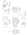
- FIG. 6A is a perspective view of an operating pin of the mount of FIG. 1 .
- FIG. 6B is a top view of FIG. 6A .
- FIG. 6C is a side view of FIG. 6B .
- FIG. 6D is a side view of FIG. 6C , fully in section, with the sectioned portion taken along the line 6 D- 6 D of FIG. 6B .
- FIG. 1 is a perspective view of an embodiment of a gun mount 10 .
- Gun mount 10 may be used, for example, to mount a gun in an opening, such as a door or window, in a structure.
- the structure to which mount 10 is fixed may be mobile or immobile.
- Mobile structures may include air, land, space, and sea vehicles.
- Immobile structures may include buildings, for example.
- a gun (not shown) may be mounted on a gun cradle 12 .
- One side of the gun may interact with a spent case collector 14 that leads to a spent case and link storage container 16 .
- Container 16 may be supported by cradle 12 .
- Another side of the gun may interact with a magazine feed mechanism disposed at area 18 .
- a bar-mounted ammunition container 20 may supply ammunition to the gun in mount 10 via a flexible chute 22 .
- Gun cradle 12 may be fixed to a pintle 24 .
- gun cradle 12 is movable in azimuth and elevation on pintle 24 .
- Pintle 24 may be fixed to and supported by a longitudinal member or arm 26 having a central longitudinal axis X.
- mount 10 may include a hinge assembly 28 .
- Hinge assembly 28 may include a mounting pin 30 for fixing mount 10 to a suitable bracket located on one side of an opening in a structure.
- Another longitudinal member or arm 34 may be fixed to hinge assembly 28 using, for example, pins 35 and 36 .
- a detailed embodiment of hinge assembly 28 is disclosed in U.S. patent application Ser. No. 12/949,270.
- the other end of mount 10 may include a support member 32 .
- Support member 32 may be fixed to a side of the opening in the structure opposite the side where hinge assembly 28 is fixed such that mount 10 spans across the opening in the structure.
- An end 27 of arm 26 may include a bushing that allows end 27 to disengage from support member 32 and thereby allow arm 26 to rotate in the directions I and O shown in FIG. 1 .
- Arm 26 is rotatable with respect to arm 34 and may be locked in various positions of relative rotation.
- Arm 26 includes a locking mechanism 38 on one end.
- Locking mechanism 38 includes a through hole 40 ( FIG. 3A ) with a central axis that defines a pivot axis Y of arms 26 and 34 . Pivot axis Y is orthogonal to central axis X of arm 26 .
- Locking mechanism 38 includes a generally arcuate outer surface 42 with a plurality of notches 44 a , 44 b , 44 c , 46 formed therein. The number, location, size, and depth of notches 44 a , 44 b , 44 c , and 46 may vary, depending on the requirements of a particular application. In the embodiment shown in FIG.
- notches 44 a , 44 b , 44 c are deep notches and notches 46 are shallow notches.
- arm 34 includes a yoke 48 on one end.
- Yoke 48 includes through holes 50 ( FIG. 4A ).
- a pivot pin 52 is disposed in through hole 40 in locking mechanism 38 and in through holes 50 in yoke 48 to rotatably fix arm 26 to arm 34 .
- a locking plunger 54 is disposed in arm 34 and is translatable in arm 34 between a fully locked position ( FIG. 2D ) and a fully unlocked position ( FIG. 2F ).
- FIG. 2E shows locking plunger 54 in a transition position between the fully locked and fully unlocked positions. From its position in FIG. 2C , locking plunger 54 must be translated to the left to reach the fully locked position of FIG. 2D .
- Locking plunger 54 is biased toward locking mechanism 38 using, for example, a helical compression spring 66 .
- the structure of locking plunger 54 is shown in detail in FIGS. 5A-5F .
- Locking plunger 54 includes a locking projection 56 configured to engage notches 44 a , 44 b , 44 c , 46 in locking mechanism 38 . However, in the fully unlocked position of FIG. 2F , locking projection 56 is translated away from locking mechanism 38 and does not engage any of notches 44 a , 44 b , 44 c , 46 .
- an operating pin 58 is inserted through arm 34 and locking plunger 54 .
- operating pin 58 is used to translate locking plunger 54 between the positions shown in FIGS. 2C-F .
- operating pin 58 includes a central shaft 60 and a collar 62 disposed around central shaft 60 . Collar 62 is biased toward arm 34 by, for example, a helical compression spring 68 .
- Operating pin 58 is vertically constrained in locking plunger 54 .
- a retainer 59 FIG. 2C , which may be a collar attached to pin 58 by a spring pin, provides vertical constraint in one direction.
- An enlarged portion 57 ( FIG. 6C ) of operating pin 58 provides vertical constraint in the other direction because the outer diameter of enlarged portion 57 is larger than the diameter of the opening 55 ( FIG. 5A ) that is formed in locking plunger 54 to receive shaft 60 of operating pin 58 .
- Arm 34 includes an operating pin opening 64 ( FIGS. 4A and 4C ) for receiving collar 62 of operating pin 58 .
- Opening 64 may be formed in a flat 70 on arm 34 .
- Opening 64 includes fully locked, transition, and fully unlocked portions 72 , 74 , 76 , respectively.
- the fully locked and fully unlocked portions 72 , 76 are large enough in diameter to receive collar 62 of operating pin 58 , which is biased downwardly by spring 68 .
- Transition portion 74 is large enough to receive central shaft 60 of operating pin 58 but not large enough to receive collar 62 of operating pin 58 .
- a user lifts collar 62 of pin 58 upward, thereby compressing spring 68 .
- pin 58 may be translated to any other portion 74 , 76 of opening 64 . Translation of pin 58 causes locking plunger 54 to translate the same distance in the same direction.
- arms 26 and 34 cannot rotate with respect to each other.
- FIG. 2C locking plunger 54 is translated to the right, but is not yet fixed in the fully unlocked position.
- collar 62 is pushed downward by spring 68 into fully unlocked portion 76 of opening 64 , as shown in FIG. 2F , thereby fixing the fully unlocked position of locking plunger 54 .
- the depth of the notches 44 a , 44 b , 44 c , 46 ( FIGS. 3A and 3B ) in arcuate outer surface 42 of locking mechanism 38 may be varied so that the extent of translation of locking plunger 54 in the direction of locking mechanism 38 also varies. And, the extent of translation of locking plunger 54 in the direction of locking mechanism 38 affects the position of operating pin 58 in opening 64 .
- only notch 44 b is deep enough to enable plunger 54 to translate far enough toward locking mechanism 38 to insert collar 62 in fully locked portion 72 of opening 64 .
- projection 56 FIG.
- locking plunger 54 is disposed in notch 44 b in arcuate outer surface 42 of locking mechanism 38 , collar 62 is disposed in fully locked portion 72 of opening 64 , and arms 26 and 34 are essentially collinear. In FIG. 1 , arms 26 and 34 are essentially collinear, although plunger 54 is not shown in the fully locked position in FIG. 1 .
- Notches 44 a and 44 c are not as deep as notch 44 b and do not allow plunger 54 to translate far enough toward locking mechanism 38 for collar 62 to fit into fully locked portion 72 of opening 64 .
- Notches 44 a and 44 c only allow collar 62 to rest on flat 70 to the right of (as viewed in FIG. 4A ) locking portion 72 .
- notch 44 a corresponds to an outboard position of the gun wherein arm 26 is rotated in the direction of arrow O in FIG. 1 .
- Notch 44 c corresponds to an inboard position of the gun wherein arm 26 is rotated in the direction of arrow I in FIG. 1 .
- Notches 46 are shallower than notches 44 a , 44 b , 44 c and correspond to intermediate force-dampening positions of mount 10 .
- the number, depth and location of the notches in locking mechanism 38 may be varied for a particular application.
Landscapes
- Engineering & Computer Science (AREA)
- General Engineering & Computer Science (AREA)
- Toys (AREA)
Abstract
Description
Claims (11)
Priority Applications (1)
| Application Number | Priority Date | Filing Date | Title |
|---|---|---|---|
| US13/687,469 US8800421B1 (en) | 2012-06-13 | 2012-11-28 | Positive locking mechanism for rotating helicopter mount |
Applications Claiming Priority (2)
| Application Number | Priority Date | Filing Date | Title |
|---|---|---|---|
| US201261659165P | 2012-06-13 | 2012-06-13 | |
| US13/687,469 US8800421B1 (en) | 2012-06-13 | 2012-11-28 | Positive locking mechanism for rotating helicopter mount |
Publications (1)
| Publication Number | Publication Date |
|---|---|
| US8800421B1 true US8800421B1 (en) | 2014-08-12 |
Family
ID=51267149
Family Applications (1)
| Application Number | Title | Priority Date | Filing Date |
|---|---|---|---|
| US13/687,469 Expired - Fee Related US8800421B1 (en) | 2012-06-13 | 2012-11-28 | Positive locking mechanism for rotating helicopter mount |
Country Status (1)
| Country | Link |
|---|---|
| US (1) | US8800421B1 (en) |
Citations (29)
| Publication number | Priority date | Publication date | Assignee | Title |
|---|---|---|---|---|
| US1719147A (en) * | 1927-09-13 | 1929-07-02 | Colt S Mfg Co | Magazine feed mechanism for machine guns |
| US1799283A (en) * | 1929-11-07 | 1931-04-07 | Richard C Coupland | Ammunition-feed box |
| US2227726A (en) * | 1937-04-15 | 1941-01-07 | Cons Aircraft Corp | Retractable gun mount |
| US2252079A (en) * | 1937-12-28 | 1941-08-12 | Cons Aircraft Corp | Retractable gun mount |
| US2345747A (en) * | 1941-02-13 | 1944-04-04 | Glenn L Martin Co | Gun mount |
| US2354114A (en) * | 1941-03-04 | 1944-07-18 | Cons Vultee Aircraft Corp | Aircraft gun installation |
| US2419242A (en) * | 1943-01-01 | 1947-04-22 | John H Woodberry | Cartridge feeder and orienter |
| US4430922A (en) * | 1980-06-10 | 1984-02-14 | Disa A/S (Dansk Industri Sundikat A/S) | Gun-mount for machine guns or weapons of a similar kind |
| US4708052A (en) * | 1986-02-06 | 1987-11-24 | Salgad International Ltd. | Height adjustment apparatus for the firing barrel of a shell launcher |
| US5263397A (en) * | 1988-01-13 | 1993-11-23 | Sanderson Paul H | Plank-mounted aircraft armament system having ammunition magazine apparatus and associated mounting structure |
| US5282410A (en) * | 1992-03-16 | 1994-02-01 | Sanderson Paul H | Externally mounted aircraft ammunition magazine box structure |
| US6250196B1 (en) * | 1999-02-16 | 2001-06-26 | Paul H. Sanderson | Rotatable pintle arm assembly for supporting a machine gun |
| US6250197B1 (en) * | 1999-02-16 | 2001-06-26 | Paul H. Sanderson | Sponson tow-plate-mounted helicopter armament apparatus and associated methods |
| US6283428B1 (en) * | 1999-11-19 | 2001-09-04 | Military Systems Group, Inc. | Swing arm mount system |
| US6439098B1 (en) * | 2000-11-20 | 2002-08-27 | Michael J. Dillon | Ammunition box |
| US6729592B1 (en) * | 2001-04-24 | 2004-05-04 | Russell Kurtts | Highly adjustable support for optical devices |
| US6779430B1 (en) * | 2002-10-01 | 2004-08-24 | Paul H. Sanderson | Sponson tow plate-mounted helicopter armament apparatus and associated methods |
| US6799500B1 (en) * | 2003-04-09 | 2004-10-05 | Fn Mfg Llc | Ammunition pouch |
| US20060273125A1 (en) * | 2004-06-23 | 2006-12-07 | Thule Sweden Ab | Rotatable hitch mountable load carrier |
| US7258055B1 (en) * | 2003-09-30 | 2007-08-21 | United States Of America As Represented By The Secretary Of The Army | Machine gun mount |
| US7415790B1 (en) * | 2004-08-27 | 2008-08-26 | Andrew S. Ruhland | Slidable swing arm mount for weapon |
| US7513187B1 (en) * | 2005-10-19 | 2009-04-07 | The United States Of America As Represented By The Secretary Of The Navy | Gun mount |
| US20090094769A1 (en) * | 2007-10-15 | 2009-04-16 | Richard Wilson | Convertible broom |
| US7543524B1 (en) * | 2005-02-28 | 2009-06-09 | The United States Of America As Represented By The Secretary Of The Army | Machine gun mount |
| US7546794B1 (en) * | 2006-09-14 | 2009-06-16 | Recon/Optical, Inc. | Adjustable multi-caliber, multi-feed ammunition container |
| US7780026B1 (en) * | 2007-03-22 | 2010-08-24 | The United States Of America As Represented By The Secretary Of The Army | Band-free container packaging |
| US7963205B1 (en) * | 2008-03-27 | 2011-06-21 | Kiesler Police Supply, Inc. | Tri-mount cradle system |
| US8151684B2 (en) * | 2009-05-19 | 2012-04-10 | The United States Of America As Represented By The Secretary Of The Navy | Ammunition canister and feed system |
| US8336441B1 (en) * | 2010-11-18 | 2012-12-25 | The United States Of America As Represented By The Secretary Of The Army | Rotatable gun mount |
-
2012
- 2012-11-28 US US13/687,469 patent/US8800421B1/en not_active Expired - Fee Related
Patent Citations (31)
| Publication number | Priority date | Publication date | Assignee | Title |
|---|---|---|---|---|
| US1719147A (en) * | 1927-09-13 | 1929-07-02 | Colt S Mfg Co | Magazine feed mechanism for machine guns |
| US1799283A (en) * | 1929-11-07 | 1931-04-07 | Richard C Coupland | Ammunition-feed box |
| US2227726A (en) * | 1937-04-15 | 1941-01-07 | Cons Aircraft Corp | Retractable gun mount |
| US2252079A (en) * | 1937-12-28 | 1941-08-12 | Cons Aircraft Corp | Retractable gun mount |
| US2345747A (en) * | 1941-02-13 | 1944-04-04 | Glenn L Martin Co | Gun mount |
| US2354114A (en) * | 1941-03-04 | 1944-07-18 | Cons Vultee Aircraft Corp | Aircraft gun installation |
| US2419242A (en) * | 1943-01-01 | 1947-04-22 | John H Woodberry | Cartridge feeder and orienter |
| US4430922A (en) * | 1980-06-10 | 1984-02-14 | Disa A/S (Dansk Industri Sundikat A/S) | Gun-mount for machine guns or weapons of a similar kind |
| US4708052A (en) * | 1986-02-06 | 1987-11-24 | Salgad International Ltd. | Height adjustment apparatus for the firing barrel of a shell launcher |
| US5263397A (en) * | 1988-01-13 | 1993-11-23 | Sanderson Paul H | Plank-mounted aircraft armament system having ammunition magazine apparatus and associated mounting structure |
| US5282410A (en) * | 1992-03-16 | 1994-02-01 | Sanderson Paul H | Externally mounted aircraft ammunition magazine box structure |
| US6286411B1 (en) * | 1999-02-16 | 2001-09-11 | Paul H. Sanderson | Apparatus for operatively supporting a machine gun |
| US6250196B1 (en) * | 1999-02-16 | 2001-06-26 | Paul H. Sanderson | Rotatable pintle arm assembly for supporting a machine gun |
| US6293179B1 (en) * | 1999-02-16 | 2001-09-25 | Paul H. Sanderson | Rotatable pintle arm assembly for supporting a machine gun |
| US6250197B1 (en) * | 1999-02-16 | 2001-06-26 | Paul H. Sanderson | Sponson tow-plate-mounted helicopter armament apparatus and associated methods |
| US6283428B1 (en) * | 1999-11-19 | 2001-09-04 | Military Systems Group, Inc. | Swing arm mount system |
| US6439098B1 (en) * | 2000-11-20 | 2002-08-27 | Michael J. Dillon | Ammunition box |
| US6729592B1 (en) * | 2001-04-24 | 2004-05-04 | Russell Kurtts | Highly adjustable support for optical devices |
| US6779430B1 (en) * | 2002-10-01 | 2004-08-24 | Paul H. Sanderson | Sponson tow plate-mounted helicopter armament apparatus and associated methods |
| US6799500B1 (en) * | 2003-04-09 | 2004-10-05 | Fn Mfg Llc | Ammunition pouch |
| US7258055B1 (en) * | 2003-09-30 | 2007-08-21 | United States Of America As Represented By The Secretary Of The Army | Machine gun mount |
| US20060273125A1 (en) * | 2004-06-23 | 2006-12-07 | Thule Sweden Ab | Rotatable hitch mountable load carrier |
| US7415790B1 (en) * | 2004-08-27 | 2008-08-26 | Andrew S. Ruhland | Slidable swing arm mount for weapon |
| US7543524B1 (en) * | 2005-02-28 | 2009-06-09 | The United States Of America As Represented By The Secretary Of The Army | Machine gun mount |
| US7513187B1 (en) * | 2005-10-19 | 2009-04-07 | The United States Of America As Represented By The Secretary Of The Navy | Gun mount |
| US7546794B1 (en) * | 2006-09-14 | 2009-06-16 | Recon/Optical, Inc. | Adjustable multi-caliber, multi-feed ammunition container |
| US7780026B1 (en) * | 2007-03-22 | 2010-08-24 | The United States Of America As Represented By The Secretary Of The Army | Band-free container packaging |
| US20090094769A1 (en) * | 2007-10-15 | 2009-04-16 | Richard Wilson | Convertible broom |
| US7963205B1 (en) * | 2008-03-27 | 2011-06-21 | Kiesler Police Supply, Inc. | Tri-mount cradle system |
| US8151684B2 (en) * | 2009-05-19 | 2012-04-10 | The United States Of America As Represented By The Secretary Of The Navy | Ammunition canister and feed system |
| US8336441B1 (en) * | 2010-11-18 | 2012-12-25 | The United States Of America As Represented By The Secretary Of The Army | Rotatable gun mount |
Similar Documents
| Publication | Publication Date | Title |
|---|---|---|
| US10766599B2 (en) | Aircraft and outer shell therefor | |
| EP3733435A1 (en) | Locking mechanism for use in battery pack, lock assembly, quick-swap support frame assembly, and electric vehicle | |
| US6791501B2 (en) | Vehicle roof mount antenna | |
| US8757571B2 (en) | Cup holder | |
| US11339819B2 (en) | Lock catch, heat preservation plate assembly and refrigerator | |
| EP2573491A2 (en) | Refrigerator | |
| US20170271756A1 (en) | Connector, built-in antenna structure and unmanned aerial vehicle | |
| KR100938132B1 (en) | Door closer assembly | |
| US10309126B2 (en) | Pawl latch | |
| JP6146909B2 (en) | Power feeding device and method for assembling power feeding device | |
| US20070246619A1 (en) | Base for display device | |
| EP2436854A2 (en) | Door handle device for vehicle | |
| US8800421B1 (en) | Positive locking mechanism for rotating helicopter mount | |
| CN210239418U (en) | Hinge with damper | |
| US20150260275A1 (en) | Shifting device for vehicle | |
| KR102147878B1 (en) | Door hinge stopper for opening angle adjustment | |
| US10323438B2 (en) | Two-point lock | |
| CN202380859U (en) | Sliding support assembly and hardware assembly used for horizontal upturned window, and horizontal upturned window | |
| US20160331165A1 (en) | Lifting container holder | |
| US11205882B2 (en) | Crimping module | |
| CN110325783B (en) | Locking mechanism, holder and locking method of holder shaft arm | |
| US9802307B2 (en) | Locking intermediate link for a tool arm assembly | |
| JP6521741B2 (en) | Rail vehicle door support structure | |
| US20220212613A1 (en) | Wire harness fixing member | |
| US8336441B1 (en) | Rotatable gun mount |
Legal Events
| Date | Code | Title | Description |
|---|---|---|---|
| AS | Assignment |
Owner name: U.S. GOVERNMENT AS REPRESENTED BY THE SECRETARY OF Free format text: ASSIGNMENT OF ASSIGNORS INTEREST;ASSIGNOR:COLONNELLO, MICHAEL;REEL/FRAME:030253/0571 Effective date: 20130110 |
|
| STCF | Information on status: patent grant |
Free format text: PATENTED CASE |
|
| MAFP | Maintenance fee payment |
Free format text: PAYMENT OF MAINTENANCE FEE, 4TH YEAR, LARGE ENTITY (ORIGINAL EVENT CODE: M1551) Year of fee payment: 4 |
|
| FEPP | Fee payment procedure |
Free format text: MAINTENANCE FEE REMINDER MAILED (ORIGINAL EVENT CODE: REM.); ENTITY STATUS OF PATENT OWNER: LARGE ENTITY |
|
| LAPS | Lapse for failure to pay maintenance fees |
Free format text: PATENT EXPIRED FOR FAILURE TO PAY MAINTENANCE FEES (ORIGINAL EVENT CODE: EXP.); ENTITY STATUS OF PATENT OWNER: LARGE ENTITY |
|
| STCH | Information on status: patent discontinuation |
Free format text: PATENT EXPIRED DUE TO NONPAYMENT OF MAINTENANCE FEES UNDER 37 CFR 1.362 |
|
| FP | Lapsed due to failure to pay maintenance fee |
Effective date: 20220812 |