US7760237B2 - Imaging device having a blur-correction function - Google Patents
Imaging device having a blur-correction function Download PDFInfo
- Publication number
- US7760237B2 US7760237B2 US11/191,932 US19193205A US7760237B2 US 7760237 B2 US7760237 B2 US 7760237B2 US 19193205 A US19193205 A US 19193205A US 7760237 B2 US7760237 B2 US 7760237B2
- Authority
- US
- United States
- Prior art keywords
- image
- blur
- images
- exposure time
- capturing
- Prior art date
- Legal status (The legal status is an assumption and is not a legal conclusion. Google has not performed a legal analysis and makes no representation as to the accuracy of the status listed.)
- Expired - Fee Related, expires
Links
Images


Classifications
-
- H—ELECTRICITY
- H04—ELECTRIC COMMUNICATION TECHNIQUE
- H04N—PICTORIAL COMMUNICATION, e.g. TELEVISION
- H04N23/00—Cameras or camera modules comprising electronic image sensors; Control thereof
- H04N23/60—Control of cameras or camera modules
- H04N23/68—Control of cameras or camera modules for stable pick-up of the scene, e.g. compensating for camera body vibrations
- H04N23/682—Vibration or motion blur correction
-
- H—ELECTRICITY
- H04—ELECTRIC COMMUNICATION TECHNIQUE
- H04N—PICTORIAL COMMUNICATION, e.g. TELEVISION
- H04N23/00—Cameras or camera modules comprising electronic image sensors; Control thereof
- H04N23/60—Control of cameras or camera modules
- H04N23/68—Control of cameras or camera modules for stable pick-up of the scene, e.g. compensating for camera body vibrations
- H04N23/681—Motion detection
- H04N23/6811—Motion detection based on the image signal
-
- H—ELECTRICITY
- H04—ELECTRIC COMMUNICATION TECHNIQUE
- H04N—PICTORIAL COMMUNICATION, e.g. TELEVISION
- H04N23/00—Cameras or camera modules comprising electronic image sensors; Control thereof
- H04N23/60—Control of cameras or camera modules
- H04N23/68—Control of cameras or camera modules for stable pick-up of the scene, e.g. compensating for camera body vibrations
- H04N23/681—Motion detection
- H04N23/6812—Motion detection based on additional sensors, e.g. acceleration sensors
-
- H—ELECTRICITY
- H04—ELECTRIC COMMUNICATION TECHNIQUE
- H04N—PICTORIAL COMMUNICATION, e.g. TELEVISION
- H04N23/00—Cameras or camera modules comprising electronic image sensors; Control thereof
- H04N23/70—Circuitry for compensating brightness variation in the scene
- H04N23/73—Circuitry for compensating brightness variation in the scene by influencing the exposure time
Definitions
- the present invention relates to an imaging device having a blur-correction function.
- a blur-correcting device correcting a blur of an optical axis in an image-capturing optical system
- an imaging device including such a blur-correcting device.
- Some of these devices correct a blur by physically moving a part of the image-capturing optical system or an image sensor (or a film).
- Some others divide the exposure time to repeat image capturing and then compose a number of generated images in accordance with the number of the divisions, thereby correcting a blur (for example, disclosed in Japanese Patent No. 3424666).
- the aforesaid device which corrects a blur by physically moving part of the image-capturing optical system or the image sensor (or the film), requires an optical system appropriate for the blur correction and a driving unit driving the optical system, which causes a problem of size increase and complication of the device.
- the aforesaid device which divides the exposure time to repeat image capturing and then composes generated images in the dividing number, thereby correcting a blur, has a problem that it takes a long time to align positions in composing the images.
- an imaging device of the present invention includes: an image-capturing optical system forming an image of a subject on a surface of an image sensor; a blur-detecting unit detecting a blur of an optical axis in the image-capturing optical system; an image-capturing unit which divides a total exposure time by a predetermined dividing number to repeat image capturing, and generates a number of images corresponding to the dividing number; and a composing unit which finds a motion vector according to the images in the dividing number generated by the image-capturing unit and to the blur detected by the blur-detecting unit and composes the generated images in the dividing number according to the motion vector.
- the composing unit may compose the number of images corresponding to the dividing number by determining a scan range based on the motion vector and performing block matching of the images in the scan range.
- the composing unit may change a size of the scan range according to a time interval with which the image-capturing unit repeats the image capturing.
- the imaging device may further includes a decision unit which decides whether or not a value indicating the total exposure time is larger than a reciprocal of a value indicating a focal length of the image-capturing optical system.
- the image-capturing unit may generate images in the dividing number and the composing unit composes the generated images.
- FIG. 1 is a functional block diagram of a digital still camera 100 of this embodiment
- FIG. 2 is a flowchart showing an operation of the digital still camera 100 of this embodiment
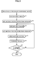
- FIG. 3 is a flowchart showing an operation of the digital still camera 100 of this embodiment
- FIG. 4 is a view showing candidate areas for a motion vector detection window.
- FIG. 5 is a view to explain an output of an angular velocity sensor 14 .
- This embodiment describes a digital still camera as an example of the imaging device of the present invention.
- a digital still camera 100 of this embodiment includes, as shown in FIG. 1 , an image-capturing lens 1 which is a zoom lens, a CCD (Charge Coupled Device) 2 , a CCD driving circuit 3 driving the CCD 2 , an analog signal processing unit 4 , a DSP (Digital Signal Processor) 5 , a camera body CPU 6 , a buffer memory 7 , an external memory 8 , and an image-composing unit 9 .
- the image-capturing lens 1 forms an image of a subject on an image-capturing surface of the CCD 2
- the CCD 2 converts the subject image to an image signal to supply the image signal to the analog signal processing unit 4
- the analog signal processing unit 4 samples the image signal photoelectrically converted by the CCD 2 , A/D-converts the sampled signal after amplifying it to a predetermined level, and supplies the resultant signal to the DSP 5 .
- the DSP 5 controls the CCD driving circuit 3 and adjusts an electronic shutter time, and it also applies digital image processing to the signal supplied from the analog signal processing unit 4 and supplies the resultant image to the buffer memory 7 .
- the buffer memory 7 temporarily stores the image that has been subjected to the image processing in the DSP 5 and supplies it to the external memory 8 and the image-composing unit 9 , when necessary.
- the external memory 8 is an external memory such as a memory card, and the image-composing unit 9 detects a later-described motion vector and composes images.
- the camera body CPU 6 is mutually connected to the aforesaid DSP 5 and buffer memory 7 to control the DSP and the buffer memory 7 .
- the digital still camera 100 further includes: a zoom encoder 10 detecting a zoom position of the image-capturing lens 1 ; a distance encoder 11 detecting information on an image-capturing distance; a lens CPU 12 ; a blur-calculating unit 13 provided in the lens CPU 12 ; and an angular velocity sensor 14 .
- the angular velocity sensor 14 which is a typical piezo-vibration sensor, detects an angular velocity of a blur by monitoring a Coriolis force. Further, the angular velocity sensor 14 amplifies the detected angular velocity to an extent such that it falls within an A/D dynamic range and supplies the angular velocity to the lens CPU 12 after A/D-converting it. Note that the angular velocity sensor 14 has a LPF (Low Pass Filter) for filtering out a high-frequency noise.
- the blur-calculating unit 13 obtains outputs of the aforesaid zoom encoder 10 , distance encoder 11 , and angular velocity sensor 14 to calculate an amount of the blur.
- the lens CPU 12 controls the image-capturing lens 1 and is mutually connected to the aforesaid camera body CPU 6 .
- the digital still camera 100 further includes: a blur-correction mode switch 15 for receiving a user operation to execute the blur correction, which is a feature of the present invention; and a release button 16 for receiving a user operation to start image capturing. Statuses of the blur-correction mode switch 15 and the release button 16 are detected by the camera body CPU 16 .
- the exposure time is divided as will be described later. A dividing number at this time is calculated based on the exposure time and a focal length.
- the camera body CPU 6 judges whether or not the release button 16 is half-pressed (Step S 1 ).
- Step S 2 the camera body CPU 6 starts image-capturing operation to judge whether or not the blur-correction mode switch 15 is ON.
- the camera body CPU 6 When the blur-correction mode switch 15 is not ON, the camera body CPU 6 performs a normal image-capturing operation. On the other hand, when the blur-correction mode switch 15 is ON, the camera body CPU 6 starts blur detection by the angular velocity sensor 14 via the lens CPU 12 , and subsequently judges whether or not the release button 16 is fully pressed (Step S 3 ).
- Step S 4 the camera body CPU 6 judges whether or not an exposure time ET is equal to or longer than a reciprocal (1/f) of a focal length f.
- the camera body CPU 6 calculates a dividing number N (Step S 5 ).
- ET represents the exposure time (unit: second)
- f represents the focal length (unit: mm) in 35 mm film equivalent terms.
- the camera body CPU 6 finds the exposure time ET according to a program diagram stored in advance in a not-shown memory in the camera body CPU 6 and finds the focal length f based on the output of the zoom encoder 10 . Then, the camera body CPU 6 calculates the dividing number N by using (Expression 1) or (Expression 1′).
- the camera body CPU 6 performs later-described processing for a composing mode (Step S 6 ).
- the camera body CPU 6 performs normal image capturing (Step S 7 ).
- the normal image capturing is performed in the same manner as that of a known art.
- the camera body CPU 6 stores in the external memory 8 (Step S 8 ) an image generated by the processing for the composing mode (Step S 6 ) or an image generated by the normal image capturing (Step S 7 ) to finish a series of the processing.
- the camera body CPU 6 records in tag information of the image (for example, EXIF information or the like) that the image composition has been performed.
- the camera body CPU 6 obtains a first image (Step S 11 ).
- the camera body CPU 6 controls the CCD 2 via the CCD driving circuit 3 to obtain the first image with the exposure time of 1/200 (1/focal length) and records the obtained image in the buffer memory 7 via the analog signal processing unit 4 and the DSP 5 .
- the proper exposure time is 1/50 second, an exposure amount is only 1 ⁇ 4 of proper exposure amount. Therefore, the obtained image is an underexposed image.
- the camera body CPU 6 sets a motion vector detection window for the image obtained at Step S 11 (Step S 12 ).
- the motion vector detection window is an area used for later-described detection of a motion vector.
- the camera body CPU 6 detects a contrast of each predetermined candidate area for the motion vector detection window.
- FIG. 4 shows the candidate areas for the motion vector detection window.
- a in FIG. 4 denotes the whole image obtained at Step S 11
- a to e represent the candidate areas for the motion vector detection window.
- the candidate areas a to e for the motion vector detection window are set at five places, that is, upper left, upper right, center, lower left, and lower right in the image A, as shown in FIG. 4 .
- the camera body CPU 6 detects the contrast in each of the candidate areas for the motion detection window, and a candidate area whose detected contrast is equal to or more than a predetermined value is judged as highly reliable and is set as the motion vector detection window area. On the other hand, a candidate area whose detected contrast is less than the predetermined value is judged as low in reliability and is not set as the motion vector detection window area (that is, this candidate area is not used for the detection of the motion vector). In the following description, it is assumed that only the center candidate area c for the motion vector detection window out of the candidate areas a to e for the motion vector detection window is set as the motion vector detection window.
- the camera body CPU 6 obtains a next image in a similar manner as that at Step S 11 (Step S 13 ). Then, it records the obtained image in the buffer memory 7 via the analog signal processing unit 4 and the DSP 5 .
- the camera body CPU 6 sets a motion vector detection window for the image obtained at Step S 13 (Step S 14 ).
- the camera body CPU 6 adds information obtained from the angular velocity sensor 14 to information on the motion vector detection window set at Step S 12 , and sets the motion vector detection window for the image obtained at Step S 13 .
- the following expression is used.
- X 2 X 1+ ⁇ X omega( t 2) ⁇ X omega( t 1) ⁇ (Expression 2)
- X 1 represents a center X coordinate of the motion vector detection window set at Step S 12
- X 2 represents a center X coordinate of the motion vector detection window that is going to be set.
- Xomega (t 2 ) and Xomega (t 1 ) represent blur amounts obtained from the output of the angular velocity sensor 14 at times t 2 , t 1 respectively.
- the horizontal axis in FIG. 5 shows the time t.
- the angular velocity sensor 14 detects an angular velocity shown in A in FIG. 5 .
- ⁇ represents the angular velocity detected by the angular velocity sensor 14
- ⁇ 0 represents a low-frequency component of the angular velocity ⁇ .
- the blur-calculating unit 13 integrates the angular velocity ⁇ , using ⁇ 0 as a reference, in order to convert the output of the angular velocity sensor 14 to the blur amount. Then the result of the integration is the blur amount Xomega shown in B in FIG. 5 .
- Xomega (t) represents the blur amount at the time t.
- the exposure timing is shown in C in FIG. 5 .
- the exposure time is quartered as previously described.
- the digital still camera 100 repeats image capturing at the four exposure timings as shown in C in FIG. 5 .
- ⁇ Xomega (t 2 ) ⁇ Xomega (t 1 ) ⁇ in (Expression 2) represents a difference between the blur amount at the time t 2 and the blur amount at the time t 1 , and corresponds to the arrow D in B in FIG. 5 .
- the camera body CPU 6 performs the same processing also for a Y direction to find a center Y coordinate. Then, the motion vector detection window with a predetermined size is set, the center thereof being the center X coordinate and the center Y coordinate.
- the camera body CPU 6 finds the motion vector (Step S 15 ).
- the camera body CPU 6 extracts an image of a portion corresponding to the motion vector detection window set at Step S 12 , from the image obtained at Step S 13 .
- block matching is performed for the image f n-1 obtained at Step S 11 and the image f n obtained at Step S 13 .
- the image which is extracted from the image f n obtained at Step S 13 is scanned in an X direction and a Y direction in a unit of prescribed pixels, the center of the scanning being the portion corresponding to the motion vector detection window set at Step S 12 in the image f n-1 obtained at Step S 11 , and a position where the correlation is the largest is found.
- the camera body CPU 6 uses the following expression to find the position where the correlation is the largest.
- fn(x i , y j ) represents a value of (x i , y j ) in an n field. Then, dx and dy are varied, and a position where D in (Expression 3) becomes the smallest is defined as the position with the largest correlation, and based on dx and dy, the motion vector based on the images is found. Then, the motion vector based on the images and the vector based on the output of the angular velocity sensor 14 are added, thereby finding a motion vector to be used for the composition.
- the scan range is basically decided by multiplying the size of the motion vector detection window by a predetermined multiplier, but in this embodiment, since the motion vector detection window is set based on the output of the angular velocity sensor 14 , the scan range can be set smaller than a conventional range. Further, the size of the scan range is changed according to an exposure time interval. With a long exposure time interval, the scan range is made larger, while with a short exposure time interval, the scan range is made smaller.
- the camera body CPU 6 composes the images in the image-composing unit 9 based on the motion vector found at Step S 15 (Step S 16 ).
- the camera body CPU 6 reads the images from the buffer memory 7 , and laps the images one on the other based on the motion vector to compose them. However, as for a portion where the second image does not overlap with the first image, image data is doubled since this portion has lower brightness. Then, the image after the composition is stored in the buffer memory 7 .
- the camera body CPU 6 judges whether or not the acquisition of images of the dividing number N (4 here) is finished (Step S 17 ). Incidentally, the number of times the image is acquired can be counted by a counter provided in the camera body CPU 6 . When the number of images corresponding to the dividing number N is acquired (Yes at Step S 17 ), the camera body CPU 6 goes to Step S 8 in FIG. 2 to finish a series of the processing.
- Step S 16 when the images are composed at Step S 16 , the image obtained from the last composition is read from the buffer memory 7 , and this image and a next image are composed.
- a blur of the optical axis in the image-capturing optical system is detected, while the total exposure time is divided by the predetermined dividing number to repeat image capturing and generate the number of images corresponding to the dividing number. Then, the motion vector is found based on the number of images and the detected blur, and the number of images are composed according to the motion vector. Therefore, it is possible to accurately find the motion vector in a short time, which enables accurate blur correction while shortening the time required for the blur correction.
- the scan range is decided based on the motion vector, and the block matching is performed in the decided scan range to compose images. Therefore, it is possible to avoid widening the scan range more than necessary to shorten the time required for the blur correction.
- the size of the scan range is changed according to the time interval with which the image-capturing unit repeats the image capturing.
- the scan range is changed in consideration of an error that is likely to occur according to the time interval, so that erroneous detection can be lessened, which enables accurate blur correction.
- the number of images corresponding to the dividing number are generated for composition. Therefore, it is possible to perform the blur correction only when the generation and composition of the dividing number of images are necessary and avoid performing unnecessary blur correction.
- this embodiment shows the example where, in setting the motion vector detection window (Step S 12 in FIG. 3 ), the motion vector detection window used for the detection of the motion vector is selected based on the contrast, from the predetermined candidate areas a to e for the motion vector detection window (see FIG. 4 ), but the size, position, number, and the like of the detection windows may be variable according to a user operation.
- Another possible configuration is such that a characteristic point of an image is extracted and an area including the characteristic point is set as the motion vector detection window. Further, an area used for the detection of a focal point may be set as the motion vector detection window.
- the motion vector in setting the motion vector detection window (Step S 12 in FIG. 3 ), if all the candidate areas have uniformly low reliability, the motion vector may be found according only to the output of the angular velocity sensor 14 , the image being judged as a low-contrast image. Further, when block matching is performed for cyclic images including stripes or the like, there is some case where several positions are obtained as positions with high correlation, resulting in erroneous finding of the motion vector. Therefore, when a predetermined level of correlation cannot be obtained, the motion vector may be found according only to the output of the angular velocity sensor 14 .
- this embodiment shows the example where the processing is repeated up to the predetermined dividing number of times, but the processing may be discontinued when a predetermined ratio or higher of the images to be composed exceeds a dynamic range.
- this embodiment shows the example where the positions of the motion vector detection windows in and after the second image are determined based on the output of the angular velocity sensor 14 , but an alternative configuration may be such that the motion vector detection windows in the first image and the second image are set at the same position, and in finding the motion vector at Step S 15 , the scan direction or the scan range is restricted based on the output of the angular velocity sensor 14 .
- this embodiment shows the example where the angular velocity sensor 14 is provided to detect a blur, but other sensor (for example, an acceleration sensor or the like) may be provided for the blur detection.
- this embodiment shows the example where (Expression 1) or (Expression 1′) is used for calculating the dividing number N, but other expression may be used for calculation, or the dividing number N may be designated by a user.
- this embodiment shows the example where, in the blur detection based on the output of the angular velocity sensor 14 , a blur at the end timing of capturing each of the number of images corresponding to the dividing number (see FIG. 5 ) is used as a basis of the blur detection, but a blur at other timing (for example, each start timing of image capturing) may be used as a basis of the blur detection.
- this embodiment shows the example where, in the image composition (Step S 16 in FIG. 3 ), the image data on the portion where the second image does not overlap with the first image is doubled since this portion have low brightness, but the portion with no overlapping may be discarded.
- the digital still camera 100 is described as an example of the imaging device, but the present invention may be applied to a digital still camera of a lens interchangeable type, or may be applied to an imaging device such as a video camera.
- a vibration sensor included in an imaging device having a function of correcting a blur of an optical axis in a so-called image-capturing optical system may be used for the processing of the present invention.
- the steps of the processing for image composition performed by the digital still camera 100 may be entirely or partly realized by a computer.
- an imaging device such as the digital still camera 100 detects a blur of an optical axis in an image-capturing optical system and divides the total exposure time by a predetermined dividing number for repeated image capturing, and the computer obtains a number of generated images corresponding to the dividing number and information indicating the detected blur.
Abstract
Description
N=ET/(1/f) (Expression 1)
N=int{ET/(1/f)}+1 (
X2=X1+{Xomega(t2)−Xomega(t1)} (Expression 2)
X m =X m-1 +{Xomega(t m)−Xomega(t m-1)} (Expression 4)
Claims (15)
Applications Claiming Priority (2)
| Application Number | Priority Date | Filing Date | Title |
|---|---|---|---|
| JP2004232762A JP4869572B2 (en) | 2004-08-09 | 2004-08-09 | Imaging device |
| JP2004-232762 | 2004-08-09 |
Publications (2)
| Publication Number | Publication Date |
|---|---|
| US20060028554A1 US20060028554A1 (en) | 2006-02-09 |
| US7760237B2 true US7760237B2 (en) | 2010-07-20 |
Family
ID=35757003
Family Applications (1)
| Application Number | Title | Priority Date | Filing Date |
|---|---|---|---|
| US11/191,932 Expired - Fee Related US7760237B2 (en) | 2004-08-09 | 2005-07-29 | Imaging device having a blur-correction function |
Country Status (2)
| Country | Link |
|---|---|
| US (1) | US7760237B2 (en) |
| JP (1) | JP4869572B2 (en) |
Cited By (4)
| Publication number | Priority date | Publication date | Assignee | Title |
|---|---|---|---|---|
| US20080309783A1 (en) * | 2007-06-13 | 2008-12-18 | Fujifilm Corporation | Image processing device and image processing program storage medium |
| US20110193976A1 (en) * | 2010-02-05 | 2011-08-11 | Hon Hai Precision Industry Co., Ltd. | System and method for capturing images |
| CN104580905A (en) * | 2014-12-31 | 2015-04-29 | 广东欧珀移动通信有限公司 | Photographing method and terminal |
| US11363211B2 (en) * | 2017-08-29 | 2022-06-14 | Jvckenwood Corporation | Image generation control device, image generation control method, and image generation control program |
Families Citing this family (12)
| Publication number | Priority date | Publication date | Assignee | Title |
|---|---|---|---|---|
| JP4522207B2 (en) * | 2004-09-17 | 2010-08-11 | キヤノン株式会社 | Camera system, camera body and interchangeable lens |
| JP4689328B2 (en) * | 2005-04-14 | 2011-05-25 | キヤノン株式会社 | Shooting system |
| TWI271998B (en) * | 2005-09-21 | 2007-01-21 | Inventec Appliances Corp | Image processing method and apparatus thereof |
| JP4888829B2 (en) * | 2006-08-16 | 2012-02-29 | カシオ計算機株式会社 | Movie processing device, movie shooting device, and movie shooting program |
| US8896712B2 (en) * | 2007-07-20 | 2014-11-25 | Omnivision Technologies, Inc. | Determining and correcting for imaging device motion during an exposure |
| US8253810B2 (en) * | 2007-12-05 | 2012-08-28 | Aptina Imaging Corporation | Method, apparatus and system for image stabilization using a single pixel array |
| US8350952B2 (en) * | 2008-06-04 | 2013-01-08 | Omnivision Technologies, Inc. | Image sensors with improved angle response |
| US8237831B2 (en) * | 2009-05-28 | 2012-08-07 | Omnivision Technologies, Inc. | Four-channel color filter array interpolation |
| JP2013197892A (en) * | 2012-03-19 | 2013-09-30 | Fujitsu Ltd | Object recognition apparatus, object recognition method, and computer program for object recognition |
| JP6124588B2 (en) * | 2012-12-27 | 2017-05-10 | キヤノン株式会社 | Image blur correction apparatus, control method therefor, program, and storage medium |
| JP6165052B2 (en) * | 2013-12-26 | 2017-07-19 | キヤノン株式会社 | Vibration correction apparatus, imaging apparatus having the same, vibration correction method, and program |
| JP6452414B2 (en) | 2014-12-03 | 2019-01-16 | キヤノン株式会社 | Image processing apparatus, imaging apparatus, image processing method, and program |
Citations (11)
| Publication number | Priority date | Publication date | Assignee | Title |
|---|---|---|---|---|
| JPH08140087A (en) | 1994-11-08 | 1996-05-31 | Sony Corp | Method and device for detecting movement and recorder with built-in camera |
| JPH09149313A (en) | 1995-11-27 | 1997-06-06 | Sanyo Electric Co Ltd | Moving vector detection method |
| US5712474A (en) * | 1993-09-29 | 1998-01-27 | Canon Kabushiki Kaisha | Image processing apparatus for correcting blurring of an image photographed by a video camera |
| US6097896A (en) | 1997-08-25 | 2000-08-01 | Nikon Corporation | Motion compensation system having motion detection signal correction |
| US20010022619A1 (en) * | 2000-01-20 | 2001-09-20 | Kenya Nishiwaki | Image-sensing apparatus for correcting blur of sensed image |
| JP2003032555A (en) | 2001-07-19 | 2003-01-31 | Olympus Optical Co Ltd | Imaging apparatus |
| JP3424666B2 (en) | 2000-09-29 | 2003-07-07 | ミノルタ株式会社 | Digital camera body and computer-readable recording medium storing a program for controlling the digital camera body |
| US6778210B1 (en) * | 1999-07-15 | 2004-08-17 | Olympus Optical Co., Ltd. | Image pickup apparatus with blur compensation |
| US20050025244A1 (en) * | 2003-07-29 | 2005-02-03 | Samsung Electronics Co., Ltd. | Apparatus for estimating motion considering correlation between blocks and method thereof |
| US6888566B2 (en) * | 1999-12-14 | 2005-05-03 | Canon Kabushiki Kaisha | Method and apparatus for uniform lineal motion blur estimation using multiple exposures |
| US7057645B1 (en) * | 1999-02-02 | 2006-06-06 | Minolta Co., Ltd. | Camera system that compensates low luminance by composing multiple object images |
-
2004
- 2004-08-09 JP JP2004232762A patent/JP4869572B2/en not_active Expired - Fee Related
-
2005
- 2005-07-29 US US11/191,932 patent/US7760237B2/en not_active Expired - Fee Related
Patent Citations (11)
| Publication number | Priority date | Publication date | Assignee | Title |
|---|---|---|---|---|
| US5712474A (en) * | 1993-09-29 | 1998-01-27 | Canon Kabushiki Kaisha | Image processing apparatus for correcting blurring of an image photographed by a video camera |
| JPH08140087A (en) | 1994-11-08 | 1996-05-31 | Sony Corp | Method and device for detecting movement and recorder with built-in camera |
| JPH09149313A (en) | 1995-11-27 | 1997-06-06 | Sanyo Electric Co Ltd | Moving vector detection method |
| US6097896A (en) | 1997-08-25 | 2000-08-01 | Nikon Corporation | Motion compensation system having motion detection signal correction |
| US7057645B1 (en) * | 1999-02-02 | 2006-06-06 | Minolta Co., Ltd. | Camera system that compensates low luminance by composing multiple object images |
| US6778210B1 (en) * | 1999-07-15 | 2004-08-17 | Olympus Optical Co., Ltd. | Image pickup apparatus with blur compensation |
| US6888566B2 (en) * | 1999-12-14 | 2005-05-03 | Canon Kabushiki Kaisha | Method and apparatus for uniform lineal motion blur estimation using multiple exposures |
| US20010022619A1 (en) * | 2000-01-20 | 2001-09-20 | Kenya Nishiwaki | Image-sensing apparatus for correcting blur of sensed image |
| JP3424666B2 (en) | 2000-09-29 | 2003-07-07 | ミノルタ株式会社 | Digital camera body and computer-readable recording medium storing a program for controlling the digital camera body |
| JP2003032555A (en) | 2001-07-19 | 2003-01-31 | Olympus Optical Co Ltd | Imaging apparatus |
| US20050025244A1 (en) * | 2003-07-29 | 2005-02-03 | Samsung Electronics Co., Ltd. | Apparatus for estimating motion considering correlation between blocks and method thereof |
Non-Patent Citations (1)
| Title |
|---|
| Japanese Patent Office Action mailed Jul. 14, 2009 and issued in corresponding Japanese Patent Application No. 2004-232762. |
Cited By (5)
| Publication number | Priority date | Publication date | Assignee | Title |
|---|---|---|---|---|
| US20080309783A1 (en) * | 2007-06-13 | 2008-12-18 | Fujifilm Corporation | Image processing device and image processing program storage medium |
| US8237805B2 (en) * | 2007-06-13 | 2012-08-07 | Fujifilm Corporation | Image processing device that executes an image process of matching two images with each other, and a non-transitory computer-readable medium that stores a program that causes a computer to operate as the image processing device |
| US20110193976A1 (en) * | 2010-02-05 | 2011-08-11 | Hon Hai Precision Industry Co., Ltd. | System and method for capturing images |
| CN104580905A (en) * | 2014-12-31 | 2015-04-29 | 广东欧珀移动通信有限公司 | Photographing method and terminal |
| US11363211B2 (en) * | 2017-08-29 | 2022-06-14 | Jvckenwood Corporation | Image generation control device, image generation control method, and image generation control program |
Also Published As
| Publication number | Publication date |
|---|---|
| US20060028554A1 (en) | 2006-02-09 |
| JP2006054518A (en) | 2006-02-23 |
| JP4869572B2 (en) | 2012-02-08 |
Similar Documents
| Publication | Publication Date | Title |
|---|---|---|
| US7760237B2 (en) | Imaging device having a blur-correction function | |
| US10021290B2 (en) | Image processing apparatus, image processing method, image processing program, and image pickup apparatus acquiring a focusing distance from a plurality of images | |
| US7260270B2 (en) | Image creating device and image creating method | |
| JP3770271B2 (en) | Image processing device | |
| US8194148B2 (en) | Image processing device, electronic camera and image processing program | |
| US7564482B2 (en) | Image capturing device, correction device, mobile phone, and correcting method | |
| US7844175B2 (en) | Photographing apparatus and method | |
| JP3848230B2 (en) | AUTOFOCUS DEVICE, IMAGING DEVICE, AUTOFOCUS METHOD, PROGRAM, AND STORAGE MEDIUM | |
| US10212347B2 (en) | Image stabilizing apparatus and its control method, image pickup apparatus, and storage medium | |
| US9508153B2 (en) | Distance measurement apparatus, imaging apparatus, distance measurement method, and program | |
| JP5532297B2 (en) | Image processing apparatus, image processing method, and program | |
| JP2007129587A (en) | Imaging apparatus, interchangeable lens apparatus, imaging control method, data processing method for distortion aberration correction and computer program | |
| US9361704B2 (en) | Image processing device, image processing method, image device, electronic equipment, and program | |
| US20180213155A1 (en) | Image stabilization apparatus and control method therefor, image capturing apparatus, and storage medium | |
| US20090207260A1 (en) | Image pickup apparatus and image pickup method | |
| US9811909B2 (en) | Image processing apparatus, distance measuring apparatus, imaging apparatus, and image processing method | |
| JP6173549B2 (en) | Image data processing device, distance calculation device, imaging device, and image data processing method | |
| JP6659126B2 (en) | Image blur correction device, image blur correction method, imaging device, and program | |
| US7463285B2 (en) | Image pickup apparatus and camera-shake correcting method therefor | |
| JP2004289709A (en) | Image pickup device, and image pickup method | |
| US7002632B2 (en) | Image pickup apparatus with precise exposure value, exposure decision method, program, and storage medium | |
| JP6645690B2 (en) | Automatic focus adjustment device, imaging device, and automatic focus adjustment method | |
| KR100674743B1 (en) | Image processor | |
| JP2019149717A (en) | Image processing apparatus, image processing method, imaging apparatus, program, and storage medium | |
| US20240073524A1 (en) | Image stabilization apparatus and method and image capturing apparatus |
Legal Events
| Date | Code | Title | Description |
|---|---|---|---|
| AS | Assignment |
Owner name: NIKON CORPORATION, JAPAN Free format text: ASSIGNMENT OF ASSIGNORS INTEREST;ASSIGNOR:USUI, KAZUTOSHI;REEL/FRAME:016804/0614 Effective date: 20050711 |
|
| STCF | Information on status: patent grant |
Free format text: PATENTED CASE |
|
| CC | Certificate of correction | ||
| FEPP | Fee payment procedure |
Free format text: PAYOR NUMBER ASSIGNED (ORIGINAL EVENT CODE: ASPN); ENTITY STATUS OF PATENT OWNER: LARGE ENTITY |
|
| FPAY | Fee payment |
Year of fee payment: 4 |
|
| MAFP | Maintenance fee payment |
Free format text: PAYMENT OF MAINTENANCE FEE, 8TH YEAR, LARGE ENTITY (ORIGINAL EVENT CODE: M1552) Year of fee payment: 8 |
|
| FEPP | Fee payment procedure |
Free format text: MAINTENANCE FEE REMINDER MAILED (ORIGINAL EVENT CODE: REM.); ENTITY STATUS OF PATENT OWNER: LARGE ENTITY |
|
| LAPS | Lapse for failure to pay maintenance fees |
Free format text: PATENT EXPIRED FOR FAILURE TO PAY MAINTENANCE FEES (ORIGINAL EVENT CODE: EXP.); ENTITY STATUS OF PATENT OWNER: LARGE ENTITY |
|
| STCH | Information on status: patent discontinuation |
Free format text: PATENT EXPIRED DUE TO NONPAYMENT OF MAINTENANCE FEES UNDER 37 CFR 1.362 |
|
| FP | Lapsed due to failure to pay maintenance fee |
Effective date: 20220720 |