US7302861B2 - Portable flow measurement apparatus having an array of sensors - Google Patents
Portable flow measurement apparatus having an array of sensors Download PDFInfo
- Publication number
- US7302861B2 US7302861B2 US11/582,203 US58220306A US7302861B2 US 7302861 B2 US7302861 B2 US 7302861B2 US 58220306 A US58220306 A US 58220306A US 7302861 B2 US7302861 B2 US 7302861B2
- Authority
- US
- United States
- Prior art keywords
- flow
- pipe
- array
- sensors
- fluid
- Prior art date
- Legal status (The legal status is an assumption and is not a legal conclusion. Google has not performed a legal analysis and makes no representation as to the accuracy of the status listed.)
- Active
Links
Images


Classifications
-
- G—PHYSICS
- G01—MEASURING; TESTING
- G01F—MEASURING VOLUME, VOLUME FLOW, MASS FLOW OR LIQUID LEVEL; METERING BY VOLUME
- G01F1/00—Measuring the volume flow or mass flow of fluid or fluent solid material wherein the fluid passes through a meter in a continuous flow
- G01F1/704—Measuring the volume flow or mass flow of fluid or fluent solid material wherein the fluid passes through a meter in a continuous flow using marked regions or existing inhomogeneities within the fluid stream, e.g. statistically occurring variations in a fluid parameter
- G01F1/708—Measuring the time taken to traverse a fixed distance
- G01F1/7082—Measuring the time taken to traverse a fixed distance using acoustic detecting arrangements
-
- G—PHYSICS
- G01—MEASURING; TESTING
- G01F—MEASURING VOLUME, VOLUME FLOW, MASS FLOW OR LIQUID LEVEL; METERING BY VOLUME
- G01F1/00—Measuring the volume flow or mass flow of fluid or fluent solid material wherein the fluid passes through a meter in a continuous flow
- G01F1/704—Measuring the volume flow or mass flow of fluid or fluent solid material wherein the fluid passes through a meter in a continuous flow using marked regions or existing inhomogeneities within the fluid stream, e.g. statistically occurring variations in a fluid parameter
- G01F1/708—Measuring the time taken to traverse a fixed distance
- G01F1/712—Measuring the time taken to traverse a fixed distance using auto-correlation or cross-correlation detection means
-
- G—PHYSICS
- G01—MEASURING; TESTING
- G01F—MEASURING VOLUME, VOLUME FLOW, MASS FLOW OR LIQUID LEVEL; METERING BY VOLUME
- G01F1/00—Measuring the volume flow or mass flow of fluid or fluent solid material wherein the fluid passes through a meter in a continuous flow
- G01F1/74—Devices for measuring flow of a fluid or flow of a fluent solid material in suspension in another fluid
Definitions
- This invention relates to an apparatus for measuring a parameter of a process flow passing within a pipe, and more particularly to a portable instrument for selectively portable flow measurement system and/or instrument having or interconnecting with an array of sensors for processing data signals therefrom to provide an output indicative of a parameter of a process flow passing through a pipe.
- the diagnostic and development system to interrogate and modify the functionality of the meter may be cumbersome and difficult to bring out into the field. These issues limit the ability to test and develop a flow measuring product in the field or at different locations within a flow system.
- Objects of the present invention include providing a portable flow measuring apparatus for measuring the speed of sound or vortical disturbances propagating through a fluid flowing in pipes in industrial processes and other related processes, for example, to determine a parameter of the process flow.
- a portable flow measurement device for measuring a parameter of a process flow flowing within a pipe.
- the device comprises at least two pressure sensor, wherein the pressure sensors provide respective pressure signals indicative of the unsteady pressure within the pipe.
- a portable processing instrument responsive to said pressure signals, provides an output signal indicative of the at least one parameter of the mixture flowing through the pipe. The portable processing instrument enables a user to modify the operation of the portable flow measurement device.
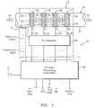
- FIG. 1 is a schematic diagram of a portable flow measurement system having a portable processing instrument and an array of sensors.
- FIG. 2 is a schematic diagram of a portable flow measurement system having a portable processing instrument and an array of sensors including a expanded schematic diagram of the portable processing instrument.
- FIG. 3 is a schematic diagram of a processing plant having a plurality of pipes with a number of sensors heads and respective transmitter units mount thereto to measure desired parameters and a portable processing instrument interconnected to one of the sensor heads, in accordance with the present invention.
- FIG. 4 is a block diagram of an apparatus for measuring the vortical field of a process flow within a pipe, in accordance with the present invention.
- FIG. 5 is a cross-sectional view of a pipe having a turbulent pipe flowing having coherent structures therein, in accordance with the present invention.
- FIG. 6 is a block diagram of an apparatus for measuring the vortical field of a process flow within a pipe, in accordance with the present invention.
- FIG. 7 a k ⁇ plot of data processed from an apparatus embodying the present invention that illustrates slope of the convective ridge, and a plot of the optimization function of the convective ridge, in accordance with the present invention.
- FIG. 8 is a block diagram of an apparatus for measuring the speed of sound propagating through a process flow flowing within a pipe, in accordance with the present invention.
- FIG. 9 a k ⁇ plot of data processed from an apparatus embodying the present invention that illustrates slope of the acoustic ridges, in accordance with the present invention.
- FIG. 1 illustrates a schematic diagram of a portable flow measurement apparatus 10 that includes a sensing device (sensor head) 16 mounted to the pipe 14 and a portable processing instrument 24 .
- the portable apparatus 10 measures a characteristic or parameter of a single phase fluid (e.g., gas and liquid) and/or multiphase fluids (e.g., gas/liquid mixtures, liquid/solid mixtures, gas/solid mixtures, steam, pulp and paper slurries, aerated gas and liquids and mixtures) 12 flowing through a pipe 14 .
- a single phase fluid e.g., gas and liquid
- multiphase fluids e.g., gas/liquid mixtures, liquid/solid mixtures, gas/solid mixtures, steam, pulp and paper slurries, aerated gas and liquids and mixtures
- the characteristics and parameters determined include the volumetric flow of the fluid, the consistency or composition of the fluid, the density of the fluid, the Mach number of the fluid, the size of particle flowing through the fluid, the air/mass ratio of the fluid, velocity of the flow, volumetric flow rate, gas volume fraction of the flow, and/or the percentage of entrained air within a liquid or slurry.
- the apparatus 10 can determine the speed at which sound propagates through the fluid flow 12 within a pipe 14 to measure particular characteristics of the single or multi-phase fluids.
- the apparatus may also determine the speed at which vortical disturbances or turbulent eddies 188 (see FIG. 5 ) propagate through the pipe 14 to determine the velocity of the fluid flow 12 .
- the flow propagating through the pipe will be referred to as a process flow with the understanding that the fluid or process flow 12 may be a single phase or multi-phase flow, as described hereinbefore.
- the sensing device 16 comprises an array of strain-based or pressure sensors 18 - 21 for measuring the unsteady pressures produced by vortical distrubances within the pipe, which are indicative of the velocity of the process flow 12 .
- the pressure signals P 1 (t)-P N (t) are provided to the portable processing unit 24 , which digitizes the pressure signals and computes the appropriate flow parameter(s).
- a cable 13 electronically connects the sensing device 16 to the portable processing instrument 24 .
- the analog pressure sensor signals P 1 (t)-P N (t) are typically 4-20 mA current loop signals.
- the array of pressure sensors comprises an array of at least two pressure sensors 18 , 19 spaced axially along the outer surface 22 of a pipe 14 , having a process flow propagating therein.
- the pressure sensors 18 - 21 are removably mounted to the pipe by any releasable fastener, such as bolts, screws and clamps.
- the array of sensors of the sensing device 16 may include any number of pressure sensors 18 - 21 greater than two sensors, such as three, four, eight, sixteen and N number of sensors between two and sixteen sensors. Generally, the accuracy of the measurement improves as the number of sensors in the array increases.
- the pressure sensors 18 - 19 measure the unsteady pressures produced by acoustical and/or vortical disturbances within the pipe 14 , which are indicative of the SOS propagating through the fluid flow 12 in the pipe and the velocity of the mixture 12 , respectively.
- the output signals (P 1 (t)-P N (t)) of the pressure sensors 18 - 21 are provided to a pre-amplifier unit 39 that amplifies the signals generated by the pressure sensors 18 - 21 .
- the portable processing instrument 24 processes the pressure measurement data P 1 (t)-P N (t) and determines the desired parameters and characteristics of the flow 12 , as described hereinbefore.
- the portable processing instrument 24 includes a signal conditioner 25 , which provides appropriate gain and filtering in preparation for digitization of the sensor signals.
- the signal conditioning unit 25 also provides power to charge amplifiers.
- a data acquisition unit 29 includes an analog to digital converter (A/D converter) for digitizing the conditioned sensor signals 27 , which are provided to the processor 30 .
- the processor 30 includes appropriate processing algorithms to determine the desired or selected parameter(s) of the process flow 12 , which will be described in greater detail hereinafter.
- the portable processing instrument 24 includes a user interface 32 to provide a means for the user to select the parameters to be measured in the process flow, and/or more importantly, to enable the user to modify particular parameters or functions in the processor 30 and/or processing algorithms.
- the user interface 32 also enables a user to modify the code of the algorithm via a graphic user interface (GUI), keyboard and/or user input signal 34 .
- GUI graphic user interface
- the user may change the operational flow range (e.g., change to 3-30 ft/sec), the frequency range over which algorithm calculates the slope for of a convective or acoustic ridge in the k- ⁇ plane (see FIGS.
- the user interface may even allow a user to post process data collected and stored b the portable processing instrument 24 .
- the laptop computer may operate using an operating system such as Windows XP®, a high-level technical computing language and interactive development environment such as MatLab®, and a graphic user interface (GUI).
- the laptop computer runs the appropriate application program to acquire the pressure sensor signals P 1 (t)-P N (t) and apply signal processing algorithms to the data to compute the appropriate flow parameters, including flow velocity, volumetric flow, speed of sound of the medium and interpretation of sound speed into compositional parameters.
- the portable processing instrument 24 may be located as far away from the sensing device 12 as 200 feet.
- the signal conditioning unit 25 for the portable instrument 24 has a filter board containing current sense resistors for the current loop input signals, as well as high and low pass filters for AC coupling and anti-alias filtering.
- the outputs 27 of the filter board are sent to the data acquisition unit 29 located in one of the PCMCIA slots of the laptop computer for example.
- the portable instrument 24 also includes a power supply that is provided to the sensing device 16 .
- the gain of the filters may be set to 1, 2, 4 and 8.
- the data acquisition card has a 16-Bit A/D and a sample rate of up to 25 KHz per channel, which meet the National specs for National Instruments DAQCard 6036E.
- the laptop computer 29 , 30 , 32 may be a Dell Lattitude C640, Inspiron 4150 or equivalent having a Pentium 4, 2.0 GHz or higher processor.
- the laptop computer may also include an internal 10/100 network connection or an internal 56K modem to transmit data or receive commands from a remote location (e.g., external from the laptop computer) via the user input signal, for example.
- Software loaded onto the computer may include Mathworks Matlab with data acquisition toolbox and signal processing toolbox. Also, National Instruments NIDAQ Version 6.9.2 or higher software may be loaded into the computer.
- a processing algorithm and GUI are also loaded onto the laptop computer for processing the input data from the array of sensors 18 - 21 of the sensing device 16 to provide the desired output to the user indicative of a parameter of the process flow 12 propagating through the pipe 14 .
- the combined portable instrument 24 and the sensing device 16 function as flow meter similar to that described in U.S. patent application, Ser. No. 10/007,749 filed Nov. 7, 2001; U.S. patent application, Ser. No. 10/007,736 filed Nov. 8, 2001; U.S. patent application Ser. No. 09/729,994, filed Dec. 4, 2000; U.S. patent application, Ser. No. 10/349,716 filed Jan. 23, 2003; U.S. patent application, Ser. No. 10/376,427 filed Feb. 26, 2003; U.S. Provisional Patent Application, Ser. No. 60/425,436 filed Nov. 12, 2002; and U.S. Provisional Patent Application, Ser. No. 60/451,685 filed Mar. 4, 2003, which are all incorporated herein by reference.
- the portable instrument 24 can effectively function as a transmitter unit 36 , which are permanently installed.
- the portable features of the processing instrument 24 and the removability of the sensing device 16 enables the portable flow measurement apparatus 10 to function in a number of different ways.
- the portable apparatus 10 may be used as demonstration unit that may be transported from plant to plant or location to location within an industrial plant to demonstrate the capabilities of a similar flow device having an array of sensors.
- the portable flow measurement apparatus 10 may be used to determine the robustness and capabilities of new applications for similar array based meter.
- the utility of the portable apparatus is further enhanced by the user interface that provides the capability to modify various parameters of the algorithms and functions programmed into the processor 30 . The user interface even allows a user to modify the algorithms at the desired test location.
- the portable measurement apparatus 10 may be used as a development tool by enabling a user to temporarily mount the sensor array to a pipe and use the portable instrument 10 to measure the desired parameter of the flow in the pipe.
- the GUI enables a user to diagnose, change parameters in the processing algorithm and vary parameters conditioning of the input signals.
- the portable flow measurement apparatus 10 may also be used to troubleshoot and/or optimize an industrial flow process.
- the features of the present invention allow one or more portable apparatus 10 to be located on desired process pipes for a specific period of time to measure and characterized the process flow 12 in the respective pipes 14 . After a desired time period, the portable apparatus 10 may be moved to other locations to further characterize and trouble shoot the process system.
- the configurability and reprogramming and modification of the operating parameters also allows the portable apparatus 10 to function on any number of pipes having various types of fluid flow 12 flowing therein without having a specific apparatus for each location.
- the present invention allows the fluid flowing within a pipe to be measured and characterized when it is not economically feasible to permanently install measurement devices at all the desired locations to troubleshoot or characterize a process.
- FIG. 3 illustrates another capability of the present invention.
- a processing plant 34 is shown having a plurality of pipes 16 with a number of sensors heads 12 and respective processing units (or transmitters) 36 mount thereto to measure desired parameters.
- the portable processing instrument 24 may be used as a troubleshooting instrument to help identify problems with the sensing unit 16 or transmitter 36 by disconnecting a transmitter unit 36 and temporarily substitute the portable processing instrument 24 .
- a plant 34 or location may simply have a plurality of sensing units mounted to pipes throughout the plant and having no transmitters for some or all of the sensing units 16 .
- the portable unit 24 may be used to pole or selectively process the data from a desired sensing unit to thereby provide flow data on an intermittent or scheduled basis.
- the sensors 18 - 21 may be permanently or otherwise non-removably mounted to the pipes in this embodiment.
- the pressure sensors may be ported within a spool piece or section of pipe 14 .
- the apparatus 10 has the ability to measure the speed of sound (SOS) and flow rate (or velocity) using one or both of the following techniques described herein below:
- the first technique measures unsteady pressures created by acoustical disturbances propagating through the flow 12 to determine the speed of sound (SOS) propagating through the flow. Knowing the pressure and/or temperature of the flow and the speed of sound of the acoustical disturbances, the processing unit 24 can determine determined include the volumetric flow of the fluid, the consistency or composition of the fluid, the density of the fluid, the Mach number of the fluid, the size of particle flowing through the fluid, the air/mass ratio of the fluid, and/or the percentage of entrained air within a liquid or slurry, such as that described in U.S. patent application Ser. No. 10/349,716, filed Jan. 23, 2003, U.S. patent application Ser. No. 10/376,427, filed Feb. 26, 2003, U.S. patent application Ser. No. 10/762,410, filed Jan. 21, 2004, which are all incorporated by reference.
- the second technique measures the velocities associated with unsteady flow fields and/or pressure disturbances created by vortical disturbances or “eddies” 118 (see FIG. 5 ) to determine the velocity of the flow 12 .
- the pressure sensors 18 - 21 measure the unsteady pressures P 1 -P N created by the vortical disturbances as these disturbances convect within the flow 12 through the pipe 14 in a known manner, as shown in FIG. 5 . Therefore, the velocity of these vortical disturbances is related to the velocity of the flow 12 and hence the volumetric flow rate may be determined, as will be described in greater detail hereinafter.
- the apparatus 110 can measure the volumetric flow rate of a single phase fluid 12 (e.g., gas and liquid) and/or a multi-phase mixture 12 (e.g., process flow) flowing through a pipe.
- a single phase fluid 12 e.g., gas and liquid
- a multi-phase mixture 12 e.g., process flow
- the flow meter 10 includes a sensing unit 16 comprising an array of sensors (or transducers) 18 - 21 spaced axially along a pipe 14 , having a process flow 12 propagating therein.
- the sensors measure the unsteady and/or stochastic pressures of the fluid flowing within the pipe, which are indicative of the velocity of the process flow 12 .
- the amplified output signals (P 1 (t)-P N (t)) of the sensors 18 - 21 are provided to the processor 24 , which processes the measurement data of the stochastic parameters to determine the flow velocity 142 and/or the volumetric flow rate 140 .
- the measurement is derived by interpreting a stochastic parameter within the process piping using multiple sensors 18 - 21 displaced axially over a predetermined length.
- the flow meter 10 measures the velocities associated with stochastic pressure fields associate with the vortical eddies 188 ( FIG. 5 ) propagating with the flow 12 to determine the velocity of the flow 12 . Therefore, the velocity of the unsteady pressures is related to the velocity of the flow 12 and hence the volumetric flow rate may be determined, as will be described in greater detail hereinafter.
- the flow meter 10 has an array of at least two sensors 18 , 19 , located at two locations x 1 ,x 2 axially along the pipe 14 .
- the sensor array may include more than two sensors as depicted by sensors 20 , 21 at locations x 3 and x N .
- the stochastic pressures may be measured through sensors 18 - 21 .
- the sensors provide time-varying signals P 1 (t),P 2 (t),P 3 (t),P N (t) to the portable processing instrument 24 .
- the processor 30 calculates the Fourier transform of the time-based input signals P 1 (t)-P N (t) and provide complex frequency domain (or frequency based) signals P 1 ( ⁇ ),P 2 ( ⁇ ),P 3 ( ⁇ ),P N ( ⁇ ) indicative of the frequency content of the input signals.
- FFT's any other technique for obtaining the frequency domain characteristics of the signals P 1 (t)-P N (t), may be used.
- the present invention may use temporal and spatial filtering to precondition the signals to effectively filter out the common mode characteristics P common mode and other long wavelength (compared to the sensor spacing) characteristics in the pipe 14 by differencing adjacent sensors and retain a substantial portion of the stochastic parameter associated with the flow field and any other short wavelength (compared to the sensor spacing) low frequency stochastic parameters.
- the processor 30 uses the frequency signals P 1 ( ⁇ )-P N ( ⁇ )to provide a flow signal 140 indicative of the volumetric flow rate of the process flow 12 and/or a velocity signal 142 indicative of the velocity of the process flow using array processing algorithms and techniques.
- One technique of determining the convection velocity of the turbulent eddies 188 within the process flow 12 is by characterizing the convective ridge of the resulting unsteady pressures using an array of sensors or other beam forming techniques, similar to that described in U.S. patent application, Ser. No. and U.S. patent application, Ser. No. 09/729,994, filed Dec. 4, 2000, now U.S. Pat. No. 6,609,069, which are incorporated herein by reference.
- the flow metering methodology uses the convection velocity of coherent structures within pipe flows 12 to determine the volumetric flow rate.
- the convection velocity of the eddies 188 is determined by applying arraying processing techniques to determine the speed at which the eddies convect past the axial array of sensors distributed along the pipe 14 , similar to that used in the radar and sonar fields.
- the array processing algorithms determine the speed of the stochastic parameters by characterizing both the temporal and spatially frequency characteristics of the flow field. For a series of coherent eddies 188 convecting past a fixed array of sensors, the temporal and spatial frequency content of stochastic fluctuations are related through the following relationship:
- k ⁇ U convect
- ⁇ the temporal frequency in rad/sec
- U convect the convection velocity
- K- ⁇ plots are essentially three-dimensional power spectra in which the power of a sound field is decomposed into bins corresponding to specific spatial wave numbers and temporal frequencies.
- the power associated with the unsteady pressure fields convecting with the flow is distributed in regions, which satisfies the dispersion relationship developed above. This region is termed “the convective ridge” (Beranek, 1992) and the slope of this ridge on a k-w plot indicates the convective velocity of the stochastic field.
- the convective velocity of eddies 188 can be determined by constructing a k- ⁇ plot from the output of a phased array of sensor and identifying the slope of the convective ridge.
- the apparatus 110 of FIG. 4 is based on the observation that unsteady pressures of a moving fluid vary the signal, which can be sensed by sensors 140 , 142 , and that a eddies 188 moves at either the same velocity as the moving fluid, or at a velocity that can be correlated to the velocity of the moving fluid.
- Convective eddies 188 parameters in a flowing fluid can be viewed as parameters that are fixed to the fluid.
- a portable apparatus 150 for determining a volumetric flow rate of a fluid 12 within a conduit (pipe) 14 is shown as including an array of sensors 152 , 154 disposed axially along the pipe for sensing respective stochastic signals propagating between the sensors 140 , 142 within the pipe at their respective locations.
- Each sensor 18 - 21 provides a signal indicating an unsteady pressure at the location of each sensor, at each instant in a series of sampling instants.
- a data accumulator 156 accumulates the signals P 1 (t) and P 2 (t) from the sensors, and provides the data accumulated over a sampling interval to a processor 158 , which performs a spatial-temporal (two-dimensional) transform of the sensor data, from the xt domain to the k- ⁇ domain, and then calculates the power in the k- ⁇ plane, as represented by k- ⁇ plot.
- the processor 158 determines the wavelength and so the (spatial) wavenumber k, and also the (temporal) frequency and so the angular frequency ⁇ , of various of the spectral components of the stochastic parameter.
- the processor 158 determines the wavelength and so the (spatial) wavenumber k, and also the (temporal) frequency and so the angular frequency ⁇ , of various of the spectral components of the stochastic parameter.
- the power in the k- ⁇ plane shown in a k- ⁇ plot of FIG. 7 so determined will exhibit a structure that is called a convective ridge 161 .
- the convective ridge represents the concentration of a stochastic parameter that convects with the flow and is a mathematical manifestation of the relationship between the spatial variations and temporal variations described above.
- Such a plot will indicate a tendency for k- ⁇ pairs to appear more or less along a line 163 with some slope, the slope indicating the flow velocity, as is described in more detail below.
- the power in the k- ⁇ plane so determined is then provided to a convective ridge identifier 160 , which uses one or another feature extraction method to determine the location and orientation (slope) of any convective ridge present in the k- ⁇ plane. Finally, information including the convective ridge orientation (slope) is used by an analyzer 162 to determine the flow velocity.
- the processor 158 uses standard so-called beam forming, array processing, or adaptive array-processing algorithms, i.e. algorithms for processing the sensor signals using various delays and weighting to create suitable phase relationships between the signals provided by the different sensors, thereby creating phased antenna array functionality.
- the prior art teaches many algorithms of use in spatially and temporally decomposing a signal from a phased array of sensors, and the present invention is not restricted to any particular algorithm.
- One particular adaptive array processing algorithm is the Capon method/algorithm. While the Capon method is described as one method, the present invention contemplates the use of other adaptive array processing algorithms, such as MUSIC algorithm.
- the present invention recognizes that such techniques can be used to determine flow rate, i.e. that the signals caused by a stochastic parameter convecting with a flow are time stationary and have a coherence length long enough that it is practical to locate sensor units apart from each other and yet still be within the coherence length.
- u is the convection velocity (flow velocity).
- a convective ridge A plot of k- ⁇ pairs obtained from a spectral analysis of sensor samples associated with convective parameters portrayed so that the energy of the disturbance spectrally corresponding to pairings that might be described as a substantially straight ridge, a ridge that in turbulent boundary layer theory is called a convective ridge.
- What is being sensed are not discrete events of turbulent eddies, but rather a continuum of possibly overlapping events forming a temporally stationary, essentially white process over the frequency range of interest.
- the convective eddies 188 is distributed over a range of length scales and hence temporal frequencies.
- Disturbances 188 that convect with a fluid flow 12 past the sensor array 152 , 154 are transformed onto the convective ridge by the processor 158 , the terminology ridge being appropriate because a k- ⁇ plot indicates by one or another symbology the energy of k- ⁇ pairs in the k- ⁇ plane (i.e. the energy conveyed by the k- ⁇ spectral component).
- identifying the convective ridge within the k- ⁇ plane provides a means to determine the convective velocity.
- the convective velocity of the stochastic parameter is closely related to the average volumetric fluid velocity and therefore volumetric flow rate (flow velocity) within the pipe 14 .
- the apparatus 150 includes two sensors 152 , 154
- the present invention contemplates more than two sensors, such as 3 to 16 sensors in an array or more, for example.
- the convective ridge identifier 160 uses one or another feature extraction methodology to discern a convective ridge 161 and its orientation in the k- ⁇ plane.
- a convective ridge can be located using even manual, visual inspection.
- a so-called slant stacking method is used, a method in which the accumulated frequency of k- ⁇ pairs in the k- ⁇ plot along different rays emanating from the origin are compared, each different ray being associated with a different trial convection velocity (in that the slope of a ray is assumed to be the flow velocity or correlated to the flow velocity in a known way).
- the convective ridge identifier 160 provides information about the different trial convection velocities, information referred to generally as convective ridge information.
- the analyzer 162 examines the convective ridge information and, assuming the straight-line dispersion relation given by equation (1), determines the flow velocity and its uncertainty.
- the spatial length scales and coherence lengths of the phenomenon constrain the length scale of the array.
- sensors In the case of measuring the flow velocity by sensing vortical disturbances, sensors must be closely spaced and located within a limited axial region; for flow velocities of less than 30 ft/sec in a three-inch diameter pipe, the sensor units should usually be spaced less than 1′′ apart.
- the axial region is approximately 0.3 of the diameter of the pipe 14 .
- FIG. 7 shows an example of a k- ⁇ plot generated from a phased array of pressure sensors.
- the power contours show a well-defined convective ridge.
- a parametric optimization method was used to determine the “best” line representing the slope of the convective ridge 200 . For this case, a slope of 14.2 ft/sec was determined.
- the intermediate result of the optimization procedure is displayed in the insert, showing that optimized value is a unique and well-defined optima.
- an apparatus 210 measures the speed of sound (SOS) to determine various characteristics of the fluid flow, as described hereinbefore.
- SOS speed of sound
- the following approach may be used with any technique that measures the sound speed of a flow or speed at which sound propagates through the flow 12 .
- it is particularly synergistic with flow meters using sonar-based array processing, such as described in U.S. patent application, Ser. No. and U.S. patent application, Ser. No. 09/729,994, filed Dec. 4, 200, now U.S. Pat. No. 6,609,069, which are incorporated herein by reference.
- the sonar-based flow meter using an array of sensors to measure the speed of sound of an acoustic wave propagating through the mixture is shown and described, one will appreciate that any means for measuring the speed of sound of the acoustic wave may used to determine the entrained gas volume fraction of the mixture/fluid.
- FIG. 8 illustrates a schematic drawing of one embodiment of the present invention.
- the apparatus 210 includes a sensing device 16 comprising an array of pressure sensors (or transducers) 18 - 21 spaced axially along the outer surface 22 of a pipe 14 , having a process flow propagating therein.
- the pressure sensors measure the unsteady pressures produced by acoustical disturbances within the pipe, which are indicative of the SOS propagating through the fluid 12 .
- the output signals (P 1 -P N ) of the pressure sensors 18 - 21 are provided to the processor 24 , which processes the pressure measurement data and determines the speed of sound and gas volume fraction (GVF).
- VVF speed of sound and gas volume fraction
- the apparatus 210 has at least pressure sensors 18 - 21 disposed axially along the pipe 14 for measuring the unsteady pressure P 1 -P N of the flow 12 flowing therethrough.
- the apparatus 210 has the ability to measure the gas volume fraction by determining the speed of sound of acoustical disturbances or sound waves propagating through the flow 12 using the array of pressure sensors 18 - 21 . While the apparatus of FIG. 8 shows at least four pressure sensors 18 - 21 , the present invention contemplates an apparatus having an array of two or more pressure sensors and having as many as sixteen (16) pressure sensors.
- the apparatus 210 measures unsteady pressures created by acoustical disturbances propagating through the flow 12 to determine the speed of sound (SOS) propagating through the flow. Knowing the pressure and/or temperature of the flow and the speed of sound of the acoustical disturbances, the processing unit 24 can determine the gas volume fraction of the flow (and other characteristics of the flow), as described and shown in FIG. 8 .
- SOS speed of sound
- the apparatus 210 in FIG. 8 also contemplates providing one or more acoustic sources 27 to enable the measurement of the speed of sound propagating through the flow for instances of acoustically quiet flow.
- the acoustic source may be a device the taps or vibrates on the wall of the pipe, for example.
- the acoustic sources may be disposed at the input end of output end of the array of sensors 18 - 21 , or at both ends as shown.
- the passive noise includes noise generated by pumps, valves, motors, and the turbulent mixture itself.
- the portable apparatus 10 of the present invention measures the speed of sound (SOS) of one-dimensional sound waves propagating through the mixture to determine the gas volume fraction of the mixture. It is known that sound propagates through various mediums at various speeds in such fields as SONAR and RADAR fields.
- the speed of sound propagating through the pipe and flow 12 may be determined using a number of known techniques, such as those set forth in U.S. patent application Ser. No. 09/344,094, entitled “Fluid Parameter Measurement in Pipes Using Acoustic Pressures”, filed Jun. 25, 1999, now U.S. Pat. No. 6,354,147; U.S. patent application Ser. No. 09/729,994, filed Dec. 4, 2002, now U.S. Pat. No. 6,609,069; U.S.
- the portable apparatus 210 embodying the present invention has an array of at least two acoustic pressure sensors 18 , 19 , located at three locations x 1 ,x 2 axially along the pipe 14 .
- the sensor array may include more than two pressure sensors as depicted by pressure sensor 20 , 21 at location x 3 ,x N .
- the pressure generated by the acoustic waves may be measured through pressure sensors 18 - 21 .
- the pressure sensors 18 - 21 provide pressure time-varying signals P 1 (t),P 2 (t),P 3 (t),P N (t) to the portable processing instrument 24 .
- the processor 30 calculates the Fourier transform of the time-based input signals P 1 (t)-P N (t) and provide complex frequency domain (or frequency based) signals P 1 ( ⁇ ),P 2 ( ⁇ ),P 3 ( ⁇ ),P N ( ⁇ ) indicative of the frequency content of the input signals.
- any other technique for obtaining the frequency domain characteristics of the signals P 1 (t)-P N (t) may be used.
- the cross-spectral density and the power spectral density may be used to form a frequency domain transfer functions (or frequency response or ratios) discussed hereinafter.
- the frequency signals P 1 ( ⁇ )-P N ( ⁇ ) are fed to an array processing unit 238 which provides a signal to line 240 indicative of the speed of sound of the mixture a mix , discussed more hereinafter.
- the a mix signal is provided to a SOS processing unit 225 , similar to the processing unit 25 , which converts a mix to a percent composition of a mixture and provides a gas volume fraction output, as discussed hereinafter.
- the data from the array of sensors 18 - 21 may be processed in any domain, including the frequency/spatial domain, the temporal/spatial domain, the temporal/wave-number domain or the wave-number/frequency (k- ⁇ ) domain.
- any known array processing technique in any of these or other related domains may be used if desired, similar to the techniques used in the fields of SONAR and RADAR.
- One such technique of determining the speed of sound propagating through the flow 12 is using array processing techniques to define an acoustic ridge in the k- ⁇ plane as shown in FIG. 9 .
- the slope of the acoustic ridge is indicative of the speed of sound propagating through the flow 12 .
- This technique is similar to that described in U.S. Pat. No. 6,587,798 filed Nov. 28, 2001, titled “Method and System for Determining The Speed of Sound in a Fluid Within a Conduit”, which is incorporated herein by reference.
- the speed of sound (SOS) is determined by applying sonar arraying processing techniques to determine the speed at which the one dimensional acoustic waves propagate past the axial array of unsteady pressure measurements distributed along the pipe 14 .
- the processor 30 performs a Fast Fourier Transform (FFT) of the time-based pressure signals P 1 (t)-P N (t) to convert the pressure signal into the frequency domain.
- FFT Fast Fourier Transform
- the power of the frequency-domain pressure signals are then determined and defined in the k- ⁇ plane by using array processing algorithms (such as Capon and Music algorithms).
- the acoustic ridge in the k- ⁇ plane, as shown in the k- ⁇ plot of FIG. 9 is then determined.
- the speed of sound (SOS) is determined by measuring slope of the acoustic ridge.
- the gas volume fraction is then calculated or otherwise determined, as described hereinafter.
- the flow meter of the present invention uses known array processing techniques, in particular the Minimum Variance, Distortionless Response (MVDR, or Capon technique), to identify pressure fluctuations, which convect with the materials flowing in a conduit and accurately ascertain the velocity, and thus the flow rate, of said material.
- MVDR Minimum Variance, Distortionless Response
- These processing techniques utilize the covariance between multiple sensors 18 - 21 at a plurality of frequencies to identify signals that behave according to a given assumed model; in the case of the apparatus 210 , a model, which represents pressure variations 20 convecting at a constant speed across the pressure sensors comprising the flow meter monitoring head 12 .
- the processor 30 determines the wavelength and so the (spatial) wavenumber k, and also the (temporal) frequency and so the angular frequency ⁇ , of various spectral components of the acoustic waves created passively or actively within the pipe.
- the processor 30 determines the wavelength and so the (spatial) wavenumber k, and also the (temporal) frequency and so the angular frequency ⁇ , of various spectral components of the acoustic waves created passively or actively within the pipe.
- the power in the k- ⁇ plane shown in a k- ⁇ plot of FIG. 9 so determined will exhibit a structure that is called an acoustic ridge 261 associated with sound propagating with the flow and one associated with sound propagating against the flow.
- the acoustic ridge represents the concentration of the disturbances that propagate with and against the flow and is a mathematical manifestation of the relationship between the spatial variations and temporal variations described above.
- Such a plot will indicate a tendency for k- ⁇ pairs to appear more or less along a line with some slope, the slope indicating the speed of sound traveling in both directions, as is described in more detail below.
- the power in the k- ⁇ plane so determined is then provided to a acoustic ridge identifier, which uses one or another feature extraction method to determine the location and orientation (slope) of any acoustic ridge present in the k- ⁇ plane. Finally, information including the acoustic ridge orientation (slope) is used by an analyzer to determine the speed of sound.
- the processor 30 uses standard so-called beam forming, array processing, or adaptive array-processing algorithms, i.e. algorithms for processing the sensor signals using various delays and weighting to create suitable phase relationships between the signals provided by the different sensors, thereby creating phased antenna array functionality.
- processor 30 may be implemented in software (using a microprocessor or computer) and/or firmware, or may be implemented using analog and/or digital hardware, having sufficient memory, interfaces, and capacity to perform the functions described herein.
- each of the pressure sensors 18 - 21 include a piezoelectric film 50 attached to a unitary multi-band strap 52 to measure the unsteady pressures of the flow 12 using either technique described hereinbefore.
- the piezoelectric film sensors 18 - 21 are mounted onto a unitary substrate or web 52 which is mounted or clamped onto the outer surface 22 of the pipe 14 , which will described in greater detail hereinafter.
- the piezoelectric film sensors 18 - 21 include a piezoelectric material or film 50 to generate an electrical signal proportional to the degree that the material is mechanically deformed or stressed.
- the piezoelectric sensing element 50 is typically conformed to allow complete or nearly complete circumferential measurement of induced strain to provide a circumferential-averaged pressure signal.
- the sensors can be formed from PVDF films, co-polymer films, or flexible PZT sensors, similar to that described in “Piezo Film Sensors Technical Manual” provided by Measurement Specialties, Inc., which is incorporated herein by reference.
- a piezoelectric film sensor that may be used for the present invention is part number 1-1002405-0, LDT4-028K, manufactured by Measurement Specialties, Inc.
- the piezoelectric film material 50 is provided substantially the length of the band 44 , and therefore the circumference of the pipe 14 , the present invention contemplates that the piezoelectric film material may be disposed along a portion of the band of any length less than the circumference of the pipe.
- Piezoelectric film (“piezofilm”) 50 like piezoelectric material, is a dynamic material that develops an electrical charge proportional to a change in mechanical stress. Consequently, the piezoelectric material measures the strain induced within the pipe 14 due to unsteady or stochastic pressure variations (e.g., vortical and/or acoustical) within the process flow 12 . Strain within the pipe is transduced to an output voltage or current by the attached piezoelectric sensor 18 - 21 .
- the piezoelectrical material or film 50 may be formed of a polymer, such as polarized fluoropolymer, polyvinylidene fluoride (PVDF).
- PVDF polyvinylidene fluoride
- the pressure sensors 18 - 21 of FIG. 1 described herein may be any type of sensor, capable of measuring the unsteady (or ac or dynamic) pressures or parameter that convects with the flow within a pipe 14 , such as piezoelectric, optical, capacitive, resistive (e.g., Wheatstone bridge), accelerometers (or geophones), velocity measuring devices, displacement measuring devices, ultra-sonic devices, etc. If optical pressure sensors are used, the sensors 18 - 21 may be Bragg grating based pressure sensors, such as that described in U.S. patent application, Ser. No. 08/925,598, entitled “High Sensitivity Fiber Optic Pressure Sensor For Use In Harsh Environments”, filed Sep. 8, 1997, now U.S. Pat. No.
- a piezo-electronic pressure transducer may be used as one or more of the pressure sensors 18 - 21 and it may measure the unsteady (or dynamic or ac) pressure variations inside the pipe 14 by measuring the pressure levels inside of the pipe. These sensors may be ported within the pipe to make direct contact with the process flow 12 .
- the sensors comprise pressure sensors manufactured by PCB Piezotronics.
- PCB Piezotronics In one pressure sensor there are integrated circuit piezoelectric voltage mode-type sensors that feature built-in microelectronic amplifiers, and convert the high-impedance charge into a low-impedance voltage output.
- a Model 106B manufactured by PCB Piezotronics is used which is a high sensitivity, acceleration compensated integrated circuit piezoelectric quartz pressure sensor suitable for measuring low pressure acoustic phenomena in hydraulic and pneumatic systems.
- any strain sensing technique may be used to measure the variations in strain in the pipe, such as highly sensitive piezoelectric, electronic or electric, strain-gages and piezo-resistive strain gages attached to the pipe 12 .
- Other strain gages include resistive foil type gages having a race track configuration similar to that disclosed U.S. patent application Ser. No. 09/344,094, filed Jun. 25, 1999, now U.S. Pat. No. 6,354,147, which is incorporated herein by reference.
- the invention also contemplates strain gages being disposed about a predetermined portion of the circumference of pipe 12 . The axial placement of and separation distance ⁇ X 1 , ⁇ X 2 between the strain sensors are determined as described herein above.
- any other strain sensing technique may be used to measure the variations in strain in the pipe, such as highly sensitive piezoelectric, electronic or electric, strain gages attached to or embedded in the pipe 14 .
- the processing could function as two separate meters, a combination (simultaneous operation) of both function, or selectively chose between operations.
Abstract
Description
Here k is the wave number, defined as k=2π/λ and has units of 1/length, ω is the temporal frequency in rad/sec, and Uconvect is the convection velocity. Thus, the shorter the wavelength (larger k) is, the higher the temporal frequency.
k=ω/u,
Claims (22)
Priority Applications (1)
| Application Number | Priority Date | Filing Date | Title |
|---|---|---|---|
| US11/582,203 US7302861B2 (en) | 2003-06-06 | 2006-10-16 | Portable flow measurement apparatus having an array of sensors |
Applications Claiming Priority (3)
| Application Number | Priority Date | Filing Date | Title |
|---|---|---|---|
| US47643703P | 2003-06-06 | 2003-06-06 | |
| US10/862,234 US7121152B2 (en) | 2003-06-06 | 2004-06-07 | Portable flow measurement apparatus having an array of sensors |
| US11/582,203 US7302861B2 (en) | 2003-06-06 | 2006-10-16 | Portable flow measurement apparatus having an array of sensors |
Related Parent Applications (1)
| Application Number | Title | Priority Date | Filing Date |
|---|---|---|---|
| US10/862,234 Continuation US7121152B2 (en) | 2003-06-06 | 2004-06-07 | Portable flow measurement apparatus having an array of sensors |
Publications (2)
| Publication Number | Publication Date |
|---|---|
| US20070034017A1 US20070034017A1 (en) | 2007-02-15 |
| US7302861B2 true US7302861B2 (en) | 2007-12-04 |
Family
ID=33551602
Family Applications (2)
| Application Number | Title | Priority Date | Filing Date |
|---|---|---|---|
| US10/862,234 Active US7121152B2 (en) | 2003-06-06 | 2004-06-07 | Portable flow measurement apparatus having an array of sensors |
| US11/582,203 Active US7302861B2 (en) | 2003-06-06 | 2006-10-16 | Portable flow measurement apparatus having an array of sensors |
Family Applications Before (1)
| Application Number | Title | Priority Date | Filing Date |
|---|---|---|---|
| US10/862,234 Active US7121152B2 (en) | 2003-06-06 | 2004-06-07 | Portable flow measurement apparatus having an array of sensors |
Country Status (2)
| Country | Link |
|---|---|
| US (2) | US7121152B2 (en) |
| WO (1) | WO2005001394A2 (en) |
Cited By (2)
| Publication number | Priority date | Publication date | Assignee | Title |
|---|---|---|---|---|
| WO2015096901A1 (en) * | 2013-12-27 | 2015-07-02 | Xsens As | Sensor apparatus and method for measuring flow |
| US9410422B2 (en) | 2013-09-13 | 2016-08-09 | Chevron U.S.A. Inc. | Alternative gauging system for production well testing and related methods |
Families Citing this family (34)
| Publication number | Priority date | Publication date | Assignee | Title |
|---|---|---|---|---|
| CA2513105C (en) * | 2002-11-12 | 2013-01-08 | Cidra Corporation | An apparatus having an array of piezoelectric film sensors for measuring parameters of a process flow within a pipe |
| US7165464B2 (en) * | 2002-11-15 | 2007-01-23 | Cidra Corporation | Apparatus and method for providing a flow measurement compensated for entrained gas |
| ATE480753T1 (en) * | 2003-01-13 | 2010-09-15 | Expro Meters Inc | APPARATUS AND METHOD FOR DETERMINING THE VELOCITY OF A FLUID IN A PIPE USING ULTRASONIC SENSORS |
| WO2004065912A2 (en) * | 2003-01-21 | 2004-08-05 | Cidra Corporation | Apparatus and method for measuring unsteady pressures within a large diameter pipe |
| EP1644705B1 (en) * | 2003-06-24 | 2016-10-12 | Cidra Corporate Services, Inc. | System and method for operating a flow process |
| WO2005054789A1 (en) * | 2003-07-08 | 2005-06-16 | Cidra Corporation | Method and apparatus for measuring characteristics of core-annular flow |
| US7127360B2 (en) * | 2003-07-15 | 2006-10-24 | Cidra Corporation | Dual function flow measurement apparatus having an array of sensors |
| CA2532577C (en) * | 2003-07-15 | 2013-01-08 | Cidra Corporation | A configurable multi-function flow measurement apparatus having an array of sensors |
| US7237440B2 (en) * | 2003-10-10 | 2007-07-03 | Cidra Corporation | Flow measurement apparatus having strain-based sensors and ultrasonic sensors |
| US20050177346A1 (en) * | 2004-02-11 | 2005-08-11 | Williams Matthew R. | Process parameter monitoring system and method of use |
| US7367239B2 (en) * | 2004-03-23 | 2008-05-06 | Cidra Corporation | Piezocable based sensor for measuring unsteady pressures inside a pipe |
| WO2006099342A1 (en) * | 2005-03-10 | 2006-09-21 | Cidra Corporation | An industrial flow meter having an accessible digital interface |
| US7962293B2 (en) * | 2005-03-10 | 2011-06-14 | Expro Meters, Inc. | Apparatus and method for providing a stratification metric of a multiphase fluid flowing within a pipe |
| US20060247869A1 (en) * | 2005-04-26 | 2006-11-02 | Lucero Guillermo A | Multiphase flow meter and data system |
| US7526966B2 (en) | 2005-05-27 | 2009-05-05 | Expro Meters, Inc. | Apparatus and method for measuring a parameter of a multiphase flow |
| WO2006130499A2 (en) | 2005-05-27 | 2006-12-07 | Cidra Corporation | An apparatus and method for fiscal measuring of an aerated fluid |
| US8641813B2 (en) * | 2005-07-07 | 2014-02-04 | Expro Meters, Inc. | System and method for optimizing a gas/liquid separation process |
| US7503227B2 (en) | 2005-07-13 | 2009-03-17 | Cidra Corporate Services, Inc | Method and apparatus for measuring parameters of a fluid flow using an array of sensors |
| US7624651B2 (en) * | 2006-10-30 | 2009-12-01 | Expro Meters, Inc. | Apparatus and method for attenuating acoustic waves in pipe walls for clamp-on ultrasonic flow meter |
| US7673526B2 (en) * | 2006-11-01 | 2010-03-09 | Expro Meters, Inc. | Apparatus and method of lensing an ultrasonic beam for an ultrasonic flow meter |
| EP2092278A2 (en) | 2006-11-09 | 2009-08-26 | Expro Meters, Inc. | Apparatus and method for measuring a fluid flow parameter within an internal passage of an elongated body |
| US8346491B2 (en) * | 2007-02-23 | 2013-01-01 | Expro Meters, Inc. | Sonar-based flow meter operable to provide product identification |
| US8166801B2 (en) * | 2007-09-30 | 2012-05-01 | Los Alamos National Security, Llc | Non-invasive fluid density and viscosity measurement |
| US9042983B2 (en) * | 2007-10-31 | 2015-05-26 | Medtronic, Inc. | Implantable system for flow measurement including charge amplifier |
| US8061186B2 (en) | 2008-03-26 | 2011-11-22 | Expro Meters, Inc. | System and method for providing a compositional measurement of a mixture having entrained gas |
| US8816865B1 (en) | 2009-07-06 | 2014-08-26 | Walter T. Deacon | Method and system for measuring temperature and pressure in different regions to determine steam quality |
| US8325049B2 (en) * | 2009-07-06 | 2012-12-04 | Thermo Diagnostics Company LLC | Method and system for measuring temperature and pressure in different regions to determine steam quality |
| GB0921530D0 (en) * | 2009-12-09 | 2010-01-27 | Atmos Wave Ltd | Monitoring fluid flow in a conduit |
| US8576666B1 (en) * | 2011-06-06 | 2013-11-05 | The United States Of America As Represented By The Secretary Of The Navy | Graphical user interface for flow noise modeling, analysis, and array design |
| WO2017078714A1 (en) * | 2015-11-05 | 2017-05-11 | Halliburton Energy Services Inc. | Fluid flow metering with point sensing |
| US10502601B2 (en) | 2017-01-10 | 2019-12-10 | Expro Meters, Inc. | Detection of flow rate over dynamic range |
| US20200356124A1 (en) * | 2019-05-09 | 2020-11-12 | Fb Global Plumbing Group Llc | Electronic plumbing fixture fitting including installation check system |
| US11307075B2 (en) | 2020-03-20 | 2022-04-19 | Expro Meters, Inc. | Apparatus and method for decreasing vibrational sensitivity of strain-based measurements of fluid flow parameters for a fluid flow within a conduit |
| CN114858216B (en) * | 2022-05-07 | 2023-09-12 | 河北地质大学 | Geological disaster monitoring system based on optical fiber sensing technology |
Citations (72)
| Publication number | Priority date | Publication date | Assignee | Title |
|---|---|---|---|---|
| US2874568A (en) | 1955-12-07 | 1959-02-24 | Gulton Ind Inc | Ultrasonic flowmeter |
| US4004461A (en) | 1975-11-07 | 1977-01-25 | Panametrics, Inc. | Ultrasonic measuring system with isolation means |
| US4048853A (en) | 1974-12-11 | 1977-09-20 | Detectronic Limited | Method and apparatus for monitoring the flow of liquid and the like |
| US4080837A (en) | 1976-12-03 | 1978-03-28 | Continental Oil Company | Sonic measurement of flow rate and water content of oil-water streams |
| US4195517A (en) | 1978-12-18 | 1980-04-01 | The Foxboro Company | Ultrasonic flowmeter |
| US4248085A (en) | 1978-01-03 | 1981-02-03 | John Coulthard | Measurement of relative velocities |
| US4445389A (en) | 1981-09-10 | 1984-05-01 | The United States Of America As Represented By The Secretary Of Commerce | Long wavelength acoustic flowmeter |
| US4860590A (en) | 1986-12-09 | 1989-08-29 | Buck Albert P | Primary standard gas flow calibrator |
| US4896540A (en) | 1988-04-08 | 1990-01-30 | Parthasarathy Shakkottai | Aeroacoustic flowmeter |
| US5040415A (en) | 1990-06-15 | 1991-08-20 | Rockwell International Corporation | Nonintrusive flow sensing system |
| US5083452A (en) | 1987-12-18 | 1992-01-28 | Sensorteknikk A/S | Method for recording multi-phase flows through a transport system |
| US5218197A (en) | 1991-05-20 | 1993-06-08 | The United States Of America As Represented By The Secretary Of The Navy | Method and apparatus for the non-invasive measurement of pressure inside pipes using a fiber optic interferometer sensor |
| WO1993014382A1 (en) | 1992-01-13 | 1993-07-22 | Jon Steinar Gudmundsson | Device and method for measuring multi phase flow |
| US5285675A (en) | 1992-06-05 | 1994-02-15 | University Of Florida Research Foundation, Inc. | Acoustic fluid flow monitoring |
| US5367911A (en) | 1991-03-21 | 1994-11-29 | Halliburton Logging Services, Inc. | Device for sensing fluid behavior |
| US5398542A (en) | 1992-10-16 | 1995-03-21 | Nkk Corporation | Method for determining direction of travel of a wave front and apparatus therefor |
| GB2294137A (en) | 1994-09-23 | 1996-04-17 | Cambridge Consultants | Data processing circuits and interfaces |
| US5524475A (en) | 1994-11-10 | 1996-06-11 | Atlantic Richfield Company | Measuring vibration of a fluid stream to determine gas fraction |
| US5526844A (en) | 1986-03-04 | 1996-06-18 | Deka Products Limited Partnership | Flow conrol system |
| US5550537A (en) * | 1994-05-06 | 1996-08-27 | Endress + Hauser, Inc. | Apparatus and method for measuring mass flow rate of a moving medium |
| US5591922A (en) | 1994-05-27 | 1997-01-07 | Schlumberger Technology Corporation | Method and apparatus for measuring multiphase flows |
| US5741980A (en) | 1994-11-02 | 1998-04-21 | Foster-Miller, Inc. | Flow analysis system and method |
| US5770806A (en) | 1994-04-19 | 1998-06-23 | Valtion Teknillinen Tutkimuskeskus | Acoustic flow measurement method and measurement apparatus implementing the method |
| US5770805A (en) | 1995-10-19 | 1998-06-23 | Institut Francais Du Petrole | Method and device for measuring a parameter of a fluid having variable density |
| US5835884A (en) | 1996-10-04 | 1998-11-10 | Brown; Alvin E. | Method of determining a characteristic of a fluid |
| US5845033A (en) | 1996-11-07 | 1998-12-01 | The Babcock & Wilcox Company | Fiber optic sensing system for monitoring restrictions in hydrocarbon production systems |
| US5856622A (en) | 1995-03-20 | 1999-01-05 | Fuji Electric Co., Ltd. | Clamp-on type ultrasonic flow meter and a temperature and pressure compensation method therein |
| US5948959A (en) | 1997-05-29 | 1999-09-07 | The United States Of America As Represented By The Secretary Of The Navy | Calibration of the normal pressure transfer function of a compliant fluid-filled cylinder |
| WO1999067629A1 (en) | 1998-06-24 | 1999-12-29 | Lattice Intellectual Property Limited | Measuring the speed of sound of a gas |
| WO2000060317A1 (en) | 1999-04-01 | 2000-10-12 | Panametrics, Inc. | Clamp-on ultrasonic flow meter for low density fluids |
| US6151958A (en) | 1996-03-11 | 2000-11-28 | Daniel Industries, Inc. | Ultrasonic fraction and flow rate apparatus and method |
| WO2001002810A1 (en) | 1999-07-02 | 2001-01-11 | Cidra Corporation | Flow rate measurement using unsteady pressures |
| US6202494B1 (en) | 1997-05-28 | 2001-03-20 | Degussa-Huls Aktiengesellschaft | Process and apparatus for measuring density and mass flow |
| US6354147B1 (en) * | 1998-06-26 | 2002-03-12 | Cidra Corporation | Fluid parameter measurement in pipes using acoustic pressures |
| US6378357B1 (en) | 2000-03-14 | 2002-04-30 | Halliburton Energy Services, Inc. | Method of fluid rheology characterization and apparatus therefor |
| US6397683B1 (en) | 1998-07-22 | 2002-06-04 | Flowtec Ag | Clamp-on ultrasonic flowmeter |
| US20020095263A1 (en) | 2000-12-04 | 2002-07-18 | Gysling Daniel L. | Method and apparatus for determining the flow velocity of a fluid within a pipe |
| US6435030B1 (en) | 1999-06-25 | 2002-08-20 | Weatherford/Lamb, Inc. | Measurement of propagating acoustic waves in compliant pipes |
| US6443226B1 (en) | 2000-11-29 | 2002-09-03 | Weatherford/Lamb, Inc. | Apparatus for protecting sensors within a well environment |
| US6450037B1 (en) | 1998-06-26 | 2002-09-17 | Cidra Corporation | Non-intrusive fiber optic pressure sensor for measuring unsteady pressures within a pipe |
| US6463813B1 (en) | 1999-06-25 | 2002-10-15 | Weatherford/Lamb, Inc. | Displacement based pressure sensor measuring unsteady pressure in a pipe |
| US20020194932A1 (en) | 1999-07-02 | 2002-12-26 | Gysling Daniel L. | Flow rate measurement using unsteady pressures |
| US6532827B1 (en) | 2001-09-06 | 2003-03-18 | Kazumasa Ohnishi | Clamp-on ultrasonic flowmeter |
| US6536291B1 (en) | 1999-07-02 | 2003-03-25 | Weatherford/Lamb, Inc. | Optical flow rate measurement using unsteady pressures |
| US6550342B2 (en) | 2000-11-29 | 2003-04-22 | Weatherford/Lamb, Inc. | Circumferential strain attenuator |
| US6558036B2 (en) | 2000-11-29 | 2003-05-06 | Weatherford/Lamb, Inc. | Non-intrusive temperature sensor for measuring internal temperature of fluids within pipes |
| US20030089161A1 (en) | 2001-11-07 | 2003-05-15 | Gysling Daniel L. | Fluid density measurement using acoustic pressures for industrial sensing applications |
| US6587798B2 (en) | 2000-12-04 | 2003-07-01 | Weatherford/Lamb, Inc. | Method and system for determining the speed of sound in a fluid within a conduit |
| US20030136186A1 (en) | 2001-11-07 | 2003-07-24 | Weatherford/Lamb, Inc. | Phase flow measurement in pipes using a density meter |
| US6601458B1 (en) | 2000-03-07 | 2003-08-05 | Weatherford/Lamb, Inc. | Distributed sound speed measurements for multiphase flow measurement |
| US20030154036A1 (en) | 2002-01-23 | 2003-08-14 | Gysling Daniel L. | Apparatus and method for measuring parameters of a mixture having solid particles suspended in a fluid flowing in a pipe |
| US6698297B2 (en) | 2002-06-28 | 2004-03-02 | Weatherford/Lamb, Inc. | Venturi augmented flow meter |
| US20040069069A1 (en) | 2002-01-23 | 2004-04-15 | Gysling Daniel L. | Probe for measuring parameters of a flowing fluid and/or multiphase mixture |
| US20040144182A1 (en) | 2002-11-15 | 2004-07-29 | Gysling Daniel L | Apparatus and method for providing a flow measurement compensated for entrained gas |
| US6782150B2 (en) | 2000-11-29 | 2004-08-24 | Weatherford/Lamb, Inc. | Apparatus for sensing fluid in a pipe |
| US20040167735A1 (en) | 2002-11-22 | 2004-08-26 | Paul Rothman | Method for calibrating a volumetric flow meter having an array of sensors |
| US20040168522A1 (en) | 2002-11-12 | 2004-09-02 | Fernald Mark R. | Apparatus having an array of clamp on piezoelectric film sensors for measuring parameters of a process flow within a pipe |
| US20040199341A1 (en) | 2003-01-21 | 2004-10-07 | Gysling Daniel L. | Measurement of entrained and dissolved gases in process flow lines |
| US20040199340A1 (en) | 2003-01-13 | 2004-10-07 | Kersey Alan D. | Apparatus and method using an array of ultrasonic sensors for determining the velocity of a fluid within a pipe |
| US20040194539A1 (en) | 2003-01-13 | 2004-10-07 | Gysling Daniel L. | Apparatus for measuring parameters of a flowing multiphase mixture |
| US20040200260A1 (en) * | 2003-04-08 | 2004-10-14 | Klosterman Kurt M. | Apparatus and method for verifying the volume of liquid dispensed by a liquid-dispensing mechanism |
| US20040210404A1 (en) | 2003-01-21 | 2004-10-21 | Gysling Daniel L | Apparatus and method of measuring gas volume fraction of a fluid flowing within a pipe |
| US6813962B2 (en) | 2000-03-07 | 2004-11-09 | Weatherford/Lamb, Inc. | Distributed sound speed measurements for multiphase flow measurement |
| US20040226386A1 (en) | 2003-01-21 | 2004-11-18 | Gysling Daniel L. | Apparatus and method for measuring unsteady pressures within a large diameter pipe |
| US20040231431A1 (en) | 2003-03-04 | 2004-11-25 | James Sullivan | Apparatus having a multi-band sensor assembly for measuring a parameter of a fluid flow flowing within a pipe |
| US20040255695A1 (en) | 2002-11-15 | 2004-12-23 | Gysling Daniel L. | Apparatus and method for providing a flow measurement compensated for entrained gas |
| US6837098B2 (en) | 2003-03-19 | 2005-01-04 | Weatherford/Lamb, Inc. | Sand monitoring within wells using acoustic arrays |
| US20050005912A1 (en) | 2001-09-25 | 2005-01-13 | Klaus Joos | Method for operating a fuel supply system for an internal combustion engine in a motor vehicle |
| US6898541B2 (en) | 2000-12-04 | 2005-05-24 | Weatherford/Lamb, Inc. | Method and apparatus for determining component flow rates for a multiphase flow |
| US6959604B2 (en) | 1998-06-26 | 2005-11-01 | Cidra Corporation | Apparatus and method having an optical fiber disposed circumferentially around the pipe for measuring unsteady pressure within a pipe |
| US7013240B2 (en) | 2003-07-14 | 2006-03-14 | Daniel Industries, Inc. | Method to snapshot and playback raw data in an ultrasonic meter |
| US7032432B2 (en) | 2002-01-23 | 2006-04-25 | Cidra Corporation | Apparatus and method for measuring parameters of a mixture having liquid droplets suspended in a vapor flowing in a pipe |
Family Cites Families (3)
| Publication number | Priority date | Publication date | Assignee | Title |
|---|---|---|---|---|
| US194932A (en) * | 1877-09-04 | Improvement in lock and electric burglar-alarm | ||
| US95263A (en) * | 1869-09-28 | Sylvania | ||
| KR100396266B1 (en) * | 2001-09-26 | 2003-09-02 | 삼성전자주식회사 | Gain flattening device of a fiber amplifier |
-
2004
- 2004-06-07 US US10/862,234 patent/US7121152B2/en active Active
- 2004-06-07 WO PCT/US2004/017867 patent/WO2005001394A2/en active Application Filing
-
2006
- 2006-10-16 US US11/582,203 patent/US7302861B2/en active Active
Patent Citations (77)
| Publication number | Priority date | Publication date | Assignee | Title |
|---|---|---|---|---|
| US2874568A (en) | 1955-12-07 | 1959-02-24 | Gulton Ind Inc | Ultrasonic flowmeter |
| US4048853A (en) | 1974-12-11 | 1977-09-20 | Detectronic Limited | Method and apparatus for monitoring the flow of liquid and the like |
| US4004461A (en) | 1975-11-07 | 1977-01-25 | Panametrics, Inc. | Ultrasonic measuring system with isolation means |
| US4080837A (en) | 1976-12-03 | 1978-03-28 | Continental Oil Company | Sonic measurement of flow rate and water content of oil-water streams |
| US4248085A (en) | 1978-01-03 | 1981-02-03 | John Coulthard | Measurement of relative velocities |
| US4195517A (en) | 1978-12-18 | 1980-04-01 | The Foxboro Company | Ultrasonic flowmeter |
| US4445389A (en) | 1981-09-10 | 1984-05-01 | The United States Of America As Represented By The Secretary Of Commerce | Long wavelength acoustic flowmeter |
| US5526844A (en) | 1986-03-04 | 1996-06-18 | Deka Products Limited Partnership | Flow conrol system |
| US4860590A (en) | 1986-12-09 | 1989-08-29 | Buck Albert P | Primary standard gas flow calibrator |
| US5083452A (en) | 1987-12-18 | 1992-01-28 | Sensorteknikk A/S | Method for recording multi-phase flows through a transport system |
| US4896540A (en) | 1988-04-08 | 1990-01-30 | Parthasarathy Shakkottai | Aeroacoustic flowmeter |
| US5040415A (en) | 1990-06-15 | 1991-08-20 | Rockwell International Corporation | Nonintrusive flow sensing system |
| US5367911A (en) | 1991-03-21 | 1994-11-29 | Halliburton Logging Services, Inc. | Device for sensing fluid behavior |
| US5218197A (en) | 1991-05-20 | 1993-06-08 | The United States Of America As Represented By The Secretary Of The Navy | Method and apparatus for the non-invasive measurement of pressure inside pipes using a fiber optic interferometer sensor |
| WO1993014382A1 (en) | 1992-01-13 | 1993-07-22 | Jon Steinar Gudmundsson | Device and method for measuring multi phase flow |
| US5285675A (en) | 1992-06-05 | 1994-02-15 | University Of Florida Research Foundation, Inc. | Acoustic fluid flow monitoring |
| US5398542A (en) | 1992-10-16 | 1995-03-21 | Nkk Corporation | Method for determining direction of travel of a wave front and apparatus therefor |
| US5770806A (en) | 1994-04-19 | 1998-06-23 | Valtion Teknillinen Tutkimuskeskus | Acoustic flow measurement method and measurement apparatus implementing the method |
| US5550537A (en) * | 1994-05-06 | 1996-08-27 | Endress + Hauser, Inc. | Apparatus and method for measuring mass flow rate of a moving medium |
| US5591922A (en) | 1994-05-27 | 1997-01-07 | Schlumberger Technology Corporation | Method and apparatus for measuring multiphase flows |
| GB2294137A (en) | 1994-09-23 | 1996-04-17 | Cambridge Consultants | Data processing circuits and interfaces |
| US5741980A (en) | 1994-11-02 | 1998-04-21 | Foster-Miller, Inc. | Flow analysis system and method |
| US5524475A (en) | 1994-11-10 | 1996-06-11 | Atlantic Richfield Company | Measuring vibration of a fluid stream to determine gas fraction |
| US5856622A (en) | 1995-03-20 | 1999-01-05 | Fuji Electric Co., Ltd. | Clamp-on type ultrasonic flow meter and a temperature and pressure compensation method therein |
| US5770805A (en) | 1995-10-19 | 1998-06-23 | Institut Francais Du Petrole | Method and device for measuring a parameter of a fluid having variable density |
| US6151958A (en) | 1996-03-11 | 2000-11-28 | Daniel Industries, Inc. | Ultrasonic fraction and flow rate apparatus and method |
| US5835884A (en) | 1996-10-04 | 1998-11-10 | Brown; Alvin E. | Method of determining a characteristic of a fluid |
| US5845033A (en) | 1996-11-07 | 1998-12-01 | The Babcock & Wilcox Company | Fiber optic sensing system for monitoring restrictions in hydrocarbon production systems |
| US6202494B1 (en) | 1997-05-28 | 2001-03-20 | Degussa-Huls Aktiengesellschaft | Process and apparatus for measuring density and mass flow |
| US5948959A (en) | 1997-05-29 | 1999-09-07 | The United States Of America As Represented By The Secretary Of The Navy | Calibration of the normal pressure transfer function of a compliant fluid-filled cylinder |
| WO1999067629A1 (en) | 1998-06-24 | 1999-12-29 | Lattice Intellectual Property Limited | Measuring the speed of sound of a gas |
| US6959604B2 (en) | 1998-06-26 | 2005-11-01 | Cidra Corporation | Apparatus and method having an optical fiber disposed circumferentially around the pipe for measuring unsteady pressure within a pipe |
| US6354147B1 (en) * | 1998-06-26 | 2002-03-12 | Cidra Corporation | Fluid parameter measurement in pipes using acoustic pressures |
| US6450037B1 (en) | 1998-06-26 | 2002-09-17 | Cidra Corporation | Non-intrusive fiber optic pressure sensor for measuring unsteady pressures within a pipe |
| US6397683B1 (en) | 1998-07-22 | 2002-06-04 | Flowtec Ag | Clamp-on ultrasonic flowmeter |
| WO2000060317A1 (en) | 1999-04-01 | 2000-10-12 | Panametrics, Inc. | Clamp-on ultrasonic flow meter for low density fluids |
| US6435030B1 (en) | 1999-06-25 | 2002-08-20 | Weatherford/Lamb, Inc. | Measurement of propagating acoustic waves in compliant pipes |
| US6463813B1 (en) | 1999-06-25 | 2002-10-15 | Weatherford/Lamb, Inc. | Displacement based pressure sensor measuring unsteady pressure in a pipe |
| US6536291B1 (en) | 1999-07-02 | 2003-03-25 | Weatherford/Lamb, Inc. | Optical flow rate measurement using unsteady pressures |
| US6889562B2 (en) | 1999-07-02 | 2005-05-10 | Cidra Corporation | Flow rate measurement for industrial sensing applications using unsteady pressures |
| WO2001002810A1 (en) | 1999-07-02 | 2001-01-11 | Cidra Corporation | Flow rate measurement using unsteady pressures |
| US20020194932A1 (en) | 1999-07-02 | 2002-12-26 | Gysling Daniel L. | Flow rate measurement using unsteady pressures |
| US6691584B2 (en) * | 1999-07-02 | 2004-02-17 | Weatherford/Lamb, Inc. | Flow rate measurement using unsteady pressures |
| US6601458B1 (en) | 2000-03-07 | 2003-08-05 | Weatherford/Lamb, Inc. | Distributed sound speed measurements for multiphase flow measurement |
| US6813962B2 (en) | 2000-03-07 | 2004-11-09 | Weatherford/Lamb, Inc. | Distributed sound speed measurements for multiphase flow measurement |
| US6378357B1 (en) | 2000-03-14 | 2002-04-30 | Halliburton Energy Services, Inc. | Method of fluid rheology characterization and apparatus therefor |
| US6550342B2 (en) | 2000-11-29 | 2003-04-22 | Weatherford/Lamb, Inc. | Circumferential strain attenuator |
| US6558036B2 (en) | 2000-11-29 | 2003-05-06 | Weatherford/Lamb, Inc. | Non-intrusive temperature sensor for measuring internal temperature of fluids within pipes |
| US6868737B2 (en) | 2000-11-29 | 2005-03-22 | Weatherford/Lamb, Inc. | Circumferential strain attenuator |
| US6443226B1 (en) | 2000-11-29 | 2002-09-03 | Weatherford/Lamb, Inc. | Apparatus for protecting sensors within a well environment |
| US6782150B2 (en) | 2000-11-29 | 2004-08-24 | Weatherford/Lamb, Inc. | Apparatus for sensing fluid in a pipe |
| US6587798B2 (en) | 2000-12-04 | 2003-07-01 | Weatherford/Lamb, Inc. | Method and system for determining the speed of sound in a fluid within a conduit |
| US6898541B2 (en) | 2000-12-04 | 2005-05-24 | Weatherford/Lamb, Inc. | Method and apparatus for determining component flow rates for a multiphase flow |
| US20020095263A1 (en) | 2000-12-04 | 2002-07-18 | Gysling Daniel L. | Method and apparatus for determining the flow velocity of a fluid within a pipe |
| US6532827B1 (en) | 2001-09-06 | 2003-03-18 | Kazumasa Ohnishi | Clamp-on ultrasonic flowmeter |
| US20050005912A1 (en) | 2001-09-25 | 2005-01-13 | Klaus Joos | Method for operating a fuel supply system for an internal combustion engine in a motor vehicle |
| US6971259B2 (en) | 2001-11-07 | 2005-12-06 | Weatherford/Lamb, Inc. | Fluid density measurement in pipes using acoustic pressures |
| US20030136186A1 (en) | 2001-11-07 | 2003-07-24 | Weatherford/Lamb, Inc. | Phase flow measurement in pipes using a density meter |
| US20030089161A1 (en) | 2001-11-07 | 2003-05-15 | Gysling Daniel L. | Fluid density measurement using acoustic pressures for industrial sensing applications |
| US7032432B2 (en) | 2002-01-23 | 2006-04-25 | Cidra Corporation | Apparatus and method for measuring parameters of a mixture having liquid droplets suspended in a vapor flowing in a pipe |
| US20040069069A1 (en) | 2002-01-23 | 2004-04-15 | Gysling Daniel L. | Probe for measuring parameters of a flowing fluid and/or multiphase mixture |
| US20030154036A1 (en) | 2002-01-23 | 2003-08-14 | Gysling Daniel L. | Apparatus and method for measuring parameters of a mixture having solid particles suspended in a fluid flowing in a pipe |
| US6698297B2 (en) | 2002-06-28 | 2004-03-02 | Weatherford/Lamb, Inc. | Venturi augmented flow meter |
| US20040168522A1 (en) | 2002-11-12 | 2004-09-02 | Fernald Mark R. | Apparatus having an array of clamp on piezoelectric film sensors for measuring parameters of a process flow within a pipe |
| US20040168523A1 (en) | 2002-11-12 | 2004-09-02 | Fernald Mark R. | Apparatus having an array of piezoelectric film sensors for measuring parameters of a process flow within a pipe |
| US20040255695A1 (en) | 2002-11-15 | 2004-12-23 | Gysling Daniel L. | Apparatus and method for providing a flow measurement compensated for entrained gas |
| US20040144182A1 (en) | 2002-11-15 | 2004-07-29 | Gysling Daniel L | Apparatus and method for providing a flow measurement compensated for entrained gas |
| US20040167735A1 (en) | 2002-11-22 | 2004-08-26 | Paul Rothman | Method for calibrating a volumetric flow meter having an array of sensors |
| US20040194539A1 (en) | 2003-01-13 | 2004-10-07 | Gysling Daniel L. | Apparatus for measuring parameters of a flowing multiphase mixture |
| US20040199340A1 (en) | 2003-01-13 | 2004-10-07 | Kersey Alan D. | Apparatus and method using an array of ultrasonic sensors for determining the velocity of a fluid within a pipe |
| US20040210404A1 (en) | 2003-01-21 | 2004-10-21 | Gysling Daniel L | Apparatus and method of measuring gas volume fraction of a fluid flowing within a pipe |
| US20040199341A1 (en) | 2003-01-21 | 2004-10-07 | Gysling Daniel L. | Measurement of entrained and dissolved gases in process flow lines |
| US20040226386A1 (en) | 2003-01-21 | 2004-11-18 | Gysling Daniel L. | Apparatus and method for measuring unsteady pressures within a large diameter pipe |
| US20040231431A1 (en) | 2003-03-04 | 2004-11-25 | James Sullivan | Apparatus having a multi-band sensor assembly for measuring a parameter of a fluid flow flowing within a pipe |
| US6837098B2 (en) | 2003-03-19 | 2005-01-04 | Weatherford/Lamb, Inc. | Sand monitoring within wells using acoustic arrays |
| US20040200260A1 (en) * | 2003-04-08 | 2004-10-14 | Klosterman Kurt M. | Apparatus and method for verifying the volume of liquid dispensed by a liquid-dispensing mechanism |
| US7013240B2 (en) | 2003-07-14 | 2006-03-14 | Daniel Industries, Inc. | Method to snapshot and playback raw data in an ultrasonic meter |
Non-Patent Citations (7)
| Title |
|---|
| "Development of an array of pressure sensors with PVDF film, Experiments in Fluids 26", Jan. 8, 1999, Springer-Verlag. |
| "Noise and Vibration Control Engineering Principles and Applications", Leo L. Beranek and Istvan L. Ver, A. Wiley Interscience Publication, pp. 537-541, Aug. 1992. |
| "Two Decades of Array Signal Processing Research", The Parametric Approach, H. Krim and M. Viberg, IEEE Signal Processing Magazine, Jul. 1996, pp. 67-94. |
| "Viscous Attentuation of Acoustic Waves in Suspensions" by R.L. Gibson, Jr. and M.N. Toksoz. |
| Sonar Based Volumetric Flow and Entrained Air Measurement for Pulp and Paper Applications-By: Daniel L. Gysling & Douglas H. Loose-Jan. 24, 2003. |
| Sonar Based Volumetric Flow Meter for Chemical and Petrochemical Applications-By: Daniel L. Gysling & Douglas H. Loose-Feb. 14, 2003. |
| Sonar-Based Volumetric Flow Meter for Pulp and Paper Applications-By: Daniel L. Gysling & Douglas H. Loose-Dec. 3, 2002. |
Cited By (5)
| Publication number | Priority date | Publication date | Assignee | Title |
|---|---|---|---|---|
| US9410422B2 (en) | 2013-09-13 | 2016-08-09 | Chevron U.S.A. Inc. | Alternative gauging system for production well testing and related methods |
| WO2015096901A1 (en) * | 2013-12-27 | 2015-07-02 | Xsens As | Sensor apparatus and method for measuring flow |
| US10557731B2 (en) | 2013-12-27 | 2020-02-11 | Xsens As | Sensor apparatus and method for measuring flow |
| US11435211B2 (en) | 2013-12-27 | 2022-09-06 | Xsens As | Sensor apparatus and method for measuring flow |
| NO347547B1 (en) * | 2013-12-27 | 2024-01-08 | Xsens As | Sensor apparatus and method for measuring flow |
Also Published As
| Publication number | Publication date |
|---|---|
| WO2005001394A3 (en) | 2005-05-12 |
| US7121152B2 (en) | 2006-10-17 |
| WO2005001394A2 (en) | 2005-01-06 |
| US20050005713A1 (en) | 2005-01-13 |
| US20070034017A1 (en) | 2007-02-15 |
Similar Documents
| Publication | Publication Date | Title |
|---|---|---|
| US7302861B2 (en) | Portable flow measurement apparatus having an array of sensors | |
| US7340353B2 (en) | Dual function flow measurement apparatus having an array of sensors | |
| US7295933B2 (en) | Configurable multi-function flow measurement apparatus having an array of sensors | |
| US7430924B2 (en) | Flow measurement apparatus having strain-based sensors and ultrasonic sensors | |
| US7454981B2 (en) | Apparatus and method for determining a parameter in a wet gas flow | |
| US7437946B2 (en) | Apparatus and method for measuring a parameter of a multiphase flow | |
| US7526966B2 (en) | Apparatus and method for measuring a parameter of a multiphase flow | |
| US8061186B2 (en) | System and method for providing a compositional measurement of a mixture having entrained gas | |
| US7596987B2 (en) | Apparatus and method for providing a density measurement augmented for entrained gas | |
| US7379828B2 (en) | Method and apparatus for determining a quality metric of a measurement of a fluid parameter | |
| US7062976B2 (en) | Apparatus and method of measuring gas volume fraction of a fluid flowing within a pipe | |
| US7725270B2 (en) | Industrial flow meter having an accessible digital interface | |
| US20040168523A1 (en) | Apparatus having an array of piezoelectric film sensors for measuring parameters of a process flow within a pipe | |
| US20070055464A1 (en) | System and method for providing a compositional measurement of a mixture having entrained gas | |
| US20040255695A1 (en) | Apparatus and method for providing a flow measurement compensated for entrained gas | |
| US20070027638A1 (en) | Apparatus having an array of piezoelectric film sensors for measuring parameters of a process flow within a pipe | |
| US20050050956A1 (en) | Contact-based transducers for characterizing unsteady pressures in pipes | |
| US20050120799A1 (en) | Contact-based transducers for characterizing unsteady pressures in pipes | |
| CA2537933C (en) | An apparatus and method for providing a density measurement augmented for entrained gas |
Legal Events
| Date | Code | Title | Description |
|---|---|---|---|
| AS | Assignment |
Owner name: CIDRA CORPORATION, CONNECTICUT Free format text: ASSIGNMENT OF ASSIGNORS INTEREST;ASSIGNORS:WINSTON, CHARLES R.;SAPACK, MICHAEL A.;CURRY, PATRICK;AND OTHERS;REEL/FRAME:019853/0861;SIGNING DATES FROM 20070917 TO 20070920 |
|
| STCF | Information on status: patent grant |
Free format text: PATENTED CASE |
|
| AS | Assignment |
Owner name: EXPRO METERS, INC., CONNECTICUT Free format text: MERGER;ASSIGNOR:CIDRA CORPORATION;REEL/FRAME:021561/0100 Effective date: 20080623 Owner name: EXPRO METERS, INC.,CONNECTICUT Free format text: MERGER;ASSIGNOR:CIDRA CORPORATION;REEL/FRAME:021561/0100 Effective date: 20080623 |
|
| FPAY | Fee payment |
Year of fee payment: 4 |
|
| AS | Assignment |
Owner name: HSBC CORPORATE TRUSTEE COMAPNY (UK) LIMITED, UNITE Free format text: SECURITY AGREEMENT;ASSIGNOR:EXPRO METERS, INC.;REEL/FRAME:027630/0109 Effective date: 20111209 Owner name: HSBC CORPORATE TRUSTEE COMPANY (UK) LIMITED, UNITE Free format text: SECURITY AGREEMENT;ASSIGNOR:EXPRO METERS, INC.;REEL/FRAME:027630/0109 Effective date: 20111209 |
|
| AS | Assignment |
Owner name: HSBC CORPORATE TRUSTEE COMPANY (UK) LIMITED, AS CO Free format text: INTELLECTUAL PROPERTY SECURITY AGREEMENT;ASSIGNOR:EXPRO METERS, INC.;REEL/FRAME:033687/0078 Effective date: 20140902 |
|
| FPAY | Fee payment |
Year of fee payment: 8 |
|
| AS | Assignment |
Owner name: WEBSTER BANK, NATIONAL ASSOCIATION, CONNECTICUT Free format text: PATENT COLLATERAL ASSIGNMENT AND SECURITY AGREEMENT;ASSIGNOR:CIDRA CORPORATE SERVICES, INC.;REEL/FRAME:036818/0469 Effective date: 20150902 |
|
| AS | Assignment |
Owner name: CIDRA CORPORATE SERVICES, INC., CONNECTICUT Free format text: RELEASE AND REASSIGNMENT OF PATENTS;ASSIGNOR:WEBSTER BANK, NATIONAL ASSOCIATION;REEL/FRAME:044097/0723 Effective date: 20170929 |
|
| AS | Assignment |
Owner name: EXPRO METERS, INC., TEXAS Free format text: RELEASE BY SECURED PARTY;ASSIGNOR:HSBC CORPORATE TRUSTEE COMPANY (UK) LIMITED, AS COLLATERAL AGENT;REEL/FRAME:045271/0842 Effective date: 20180205 |
|
| MAFP | Maintenance fee payment |
Free format text: PAYMENT OF MAINTENANCE FEE, 12TH YR, SMALL ENTITY (ORIGINAL EVENT CODE: M2553); ENTITY STATUS OF PATENT OWNER: SMALL ENTITY Year of fee payment: 12 |