US6887245B2 - Surgical drill for use with a computer assisted surgery system - Google Patents
Surgical drill for use with a computer assisted surgery system Download PDFInfo
- Publication number
- US6887245B2 US6887245B2 US10/186,010 US18601002A US6887245B2 US 6887245 B2 US6887245 B2 US 6887245B2 US 18601002 A US18601002 A US 18601002A US 6887245 B2 US6887245 B2 US 6887245B2
- Authority
- US
- United States
- Prior art keywords
- drill
- emitters
- drill bit
- localizing
- guide
- Prior art date
- Legal status (The legal status is an assumption and is not a legal conclusion. Google has not performed a legal analysis and makes no representation as to the accuracy of the status listed.)
- Expired - Lifetime, expires
Links
Images


Classifications
-
- A—HUMAN NECESSITIES
- A61—MEDICAL OR VETERINARY SCIENCE; HYGIENE
- A61B—DIAGNOSIS; SURGERY; IDENTIFICATION
- A61B17/00—Surgical instruments, devices or methods, e.g. tourniquets
- A61B17/16—Bone cutting, breaking or removal means other than saws, e.g. Osteoclasts; Drills or chisels for bones; Trepans
- A61B17/17—Guides or aligning means for drills, mills, pins or wires
- A61B17/1721—Guides or aligning means for drills, mills, pins or wires for applying pins along or parallel to the axis of the femoral neck
-
- A—HUMAN NECESSITIES
- A61—MEDICAL OR VETERINARY SCIENCE; HYGIENE
- A61B—DIAGNOSIS; SURGERY; IDENTIFICATION
- A61B17/00—Surgical instruments, devices or methods, e.g. tourniquets
- A61B17/16—Bone cutting, breaking or removal means other than saws, e.g. Osteoclasts; Drills or chisels for bones; Trepans
- A61B17/17—Guides or aligning means for drills, mills, pins or wires
- A61B17/1703—Guides or aligning means for drills, mills, pins or wires using imaging means, e.g. by X-rays
-
- A—HUMAN NECESSITIES
- A61—MEDICAL OR VETERINARY SCIENCE; HYGIENE
- A61B—DIAGNOSIS; SURGERY; IDENTIFICATION
- A61B34/00—Computer-aided surgery; Manipulators or robots specially adapted for use in surgery
- A61B34/20—Surgical navigation systems; Devices for tracking or guiding surgical instruments, e.g. for frameless stereotaxis
-
- A—HUMAN NECESSITIES
- A61—MEDICAL OR VETERINARY SCIENCE; HYGIENE
- A61B—DIAGNOSIS; SURGERY; IDENTIFICATION
- A61B90/00—Instruments, implements or accessories specially adapted for surgery or diagnosis and not covered by any of the groups A61B1/00 - A61B50/00, e.g. for luxation treatment or for protecting wound edges
- A61B90/36—Image-producing devices or illumination devices not otherwise provided for
-
- A—HUMAN NECESSITIES
- A61—MEDICAL OR VETERINARY SCIENCE; HYGIENE
- A61B—DIAGNOSIS; SURGERY; IDENTIFICATION
- A61B17/00—Surgical instruments, devices or methods, e.g. tourniquets
- A61B2017/00681—Aspects not otherwise provided for
- A61B2017/00725—Calibration or performance testing
-
- A—HUMAN NECESSITIES
- A61—MEDICAL OR VETERINARY SCIENCE; HYGIENE
- A61B—DIAGNOSIS; SURGERY; IDENTIFICATION
- A61B34/00—Computer-aided surgery; Manipulators or robots specially adapted for use in surgery
- A61B34/10—Computer-aided planning, simulation or modelling of surgical operations
- A61B2034/107—Visualisation of planned trajectories or target regions
-
- A—HUMAN NECESSITIES
- A61—MEDICAL OR VETERINARY SCIENCE; HYGIENE
- A61B—DIAGNOSIS; SURGERY; IDENTIFICATION
- A61B34/00—Computer-aided surgery; Manipulators or robots specially adapted for use in surgery
- A61B34/20—Surgical navigation systems; Devices for tracking or guiding surgical instruments, e.g. for frameless stereotaxis
- A61B2034/2046—Tracking techniques
- A61B2034/2055—Optical tracking systems
-
- A—HUMAN NECESSITIES
- A61—MEDICAL OR VETERINARY SCIENCE; HYGIENE
- A61B—DIAGNOSIS; SURGERY; IDENTIFICATION
- A61B34/00—Computer-aided surgery; Manipulators or robots specially adapted for use in surgery
- A61B34/20—Surgical navigation systems; Devices for tracking or guiding surgical instruments, e.g. for frameless stereotaxis
- A61B2034/2068—Surgical navigation systems; Devices for tracking or guiding surgical instruments, e.g. for frameless stereotaxis using pointers, e.g. pointers having reference marks for determining coordinates of body points
- A61B2034/207—Divots for calibration
-
- A—HUMAN NECESSITIES
- A61—MEDICAL OR VETERINARY SCIENCE; HYGIENE
- A61B—DIAGNOSIS; SURGERY; IDENTIFICATION
- A61B90/00—Instruments, implements or accessories specially adapted for surgery or diagnosis and not covered by any of the groups A61B1/00 - A61B50/00, e.g. for luxation treatment or for protecting wound edges
- A61B90/36—Image-producing devices or illumination devices not otherwise provided for
- A61B90/37—Surgical systems with images on a monitor during operation
- A61B2090/376—Surgical systems with images on a monitor during operation using X-rays, e.g. fluoroscopy
-
- A—HUMAN NECESSITIES
- A61—MEDICAL OR VETERINARY SCIENCE; HYGIENE
- A61B—DIAGNOSIS; SURGERY; IDENTIFICATION
- A61B90/00—Instruments, implements or accessories specially adapted for surgery or diagnosis and not covered by any of the groups A61B1/00 - A61B50/00, e.g. for luxation treatment or for protecting wound edges
- A61B90/39—Markers, e.g. radio-opaque or breast lesions markers
- A61B2090/3983—Reference marker arrangements for use with image guided surgery
-
- A—HUMAN NECESSITIES
- A61—MEDICAL OR VETERINARY SCIENCE; HYGIENE
- A61B—DIAGNOSIS; SURGERY; IDENTIFICATION
- A61B34/00—Computer-aided surgery; Manipulators or robots specially adapted for use in surgery
- A61B34/10—Computer-aided planning, simulation or modelling of surgical operations
Definitions
- This invention relates to a surgical drill for use with a computer assisted surgery system.
- Computer assisted surgery systems have been developed to aid a surgeon in more accurately positioning instruments during a surgical procedure. These systems have been described for use with CT images, fluoroscopic images, and images derived from other modalities as well as without images or in conjunction with a surgical robot. When using images of a patient, they are often referred to as image guided surgery systems. These systems typically use a localizing device to track surgical instruments in real time.
- One commonly used localizing device is an optical localizer that employs a stereoscopic camera system to view infrared light emitters or reflectors that are placed on the surgical instruments.
- Other localizing devices may use electromagnetic radiation or a passive manipulator arm with position encoders at the joints.
- the computer assisted surgery system uses the information regarding the instrument's position to superimpose a representation of the instrument over the images or to generate some other graphic or alphanumeric display.
- Another problem with the approach of tracking the drill itself is that the drill bit may bend. This can cause the trajectory displayed by the computer assisted surgery system to be significantly different than the actual path of the drill bit. Bending of the drill bit is most likely to occur at a location between the drill and the body part, either as a result of deflection of the drill bit tip upon entering the body part or because of lateral forces placed on the drill by the surgeon.
- One way to alleviate this problem is to use a tool guide that allows the trajectory of the drill bit or probe to be measured as it enters the body part. Such tool guides are common in orthopaedic surgery and neurosurgery.
- the present invention provides the surgeon with improved information for more accurately inserting a drill bit or other elongate object into the body, when used with a drill guide and a computer assisted surgery system.
- one objective of the present invention is to provide a computer assisted surgery system for accurately positioning a drill bit into a body part.
- Another objective of the invention is to provide a technique and apparatus for calculating and graphically displaying the pose of a drill bit attached to a drill and passed through a drill guide by determining the poses of the drill and drill guide.
- the invention has the advantage of accurately displaying the orientation and location of the drill bit.
- Still another objective of the invention is to provide a technique and apparatus for reporting to the surgeon misalignment, malposition, or excessive bending of the drill bit relative to the drill guide.
- Yet another objective of the invention is to provide a technique and apparatus for accurately calculating and graphically displaying the pose of a drill bit attached to a drill with only a single visible localizing emitter and passed through a drill guide.
- Still another object of the invention is to provide a surgical drill, with three or more localizing emitters integrated into the drill housing, whose pose can readily be determined with the use of a localizer.
- a computer assisted surgery system including a drill and a drill guide, each outfitted with three or more localizing emitters, and an optical localizer for measuring the pose of the drill and drill guide.
- a drill bit is attached to the drill and the location of the tip of the drill determined during a calibration step in which the tip of the drill is placed against a dimple in the drill guide and the poses of the two instruments recorded.
- the drill bit is inserted through the bore of the drill guide and the poses of the drill guide and drill are recorded in real time.
- the pose of the drill bit is calculated from the orientation of the drill guide and the location of the drill.
- a graphic representation of the drill bit is then displayed on the monitor screen in an appropriate position relative to the stored images or other instruments.
- the three or more localizing emitters are integrated into the drill housing and are spaced widely apart to facilitate accurate pose determination.
- the drill may be outfitted with one or more localizing emitters.
- the distance between the drill's localizing emitter and the tip of the drill is determined.
- the pose of the drill bit is calculated from the orientation of the drill guide and the location of the drill's localizing emitters, prior to display of its representation on the monitor screen.
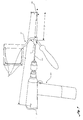
- FIG. 1 is a perspective view of a drill and drill guide with attached housings containing localizer emitters according to the present invention.
- FIG. 2 is a perspective view of a drill with localizer emitters integrated into the drill housing.
- FIG. 3 is a perspective view of the drill of FIG. 1 and a drill guide in position for calibration.
- FIG. 4 is an example of a screen display of two images and superimposed instrument representations.
- FIG. 5 is a perspective view of the drill and drill guide in position for use in drilling.
- FIG. 6 is a perspective view of a drill with a single localizer emitter integrated into the drill housing and a drill guide in position for calibration.
- FIG. 7 is a perspective view of the drill of FIG. 6 with an integrated localizer emitter and the drill guide in position for use in drilling.
- FIG. 8 is a perspective view of the drill and drill guide of FIG. 5 in position for use in drilling.
- the present invention is preferably operated in conjunction with an image guided surgery system such as is disclosed in U.S. patent application Ser. No. 09/248,133 entitled “Computer Assisted Targeting Device for Use in Orthopaedic Surgery”.
- this image guided system comprises a computer, a display monitor, an optical localizing device, and surgical instruments outfitted with infrared LEDs as localizing emitters viewable by the optical localizer.
- the system functions by acquiring x-ray images with a C-arm fluoroscope of the involved body part.
- An optical localizer is capable of measuring the location of surgical instruments outfitted with a single emitter and the pose (location and orientation) of surgical instruments with three or more emitters. The system then superimposes on the images graphic representations of the instruments at their current positions. This allows the surgeon to view, in real time, the position of the instruments with respect to an imaged body part or with respect to other instruments.
- the surgical instruments are a drill guide and a drill with an attached drill bit.
- the drill guide 110 comprises a bore or channel portion 114 through which may pass the drill bit 105 .
- the bore portion 114 has a proximal end (drill bit entrance) 107 and a distal end (drill bit exit) 108 .
- the bore portion of the drill guide functions to direct the drill bit, which passes through it on a trajectory that matches that of the bore.
- the drill guide 110 further comprises a fin assembly 112 that houses eight localizing emitters 111 , four on either face of the fin assembly 112 , in known locations relative to the bore portion 114 .
- fewer localizing emitters may be used as long as there are at least three emitters visible to the localizing device during use.
- the localizing emitters may comprise reflectors, spheres, visible spectrum emitters, or any other suitable devices capable of being accurately located by an optical localizer.
- other localizing devices may be employed including acoustic localizers, electromagnetic localizers, or passive manipulators.
- a handle 104 may be attached to the drill guide 110 to provide a convenient means for its manual positioning.
- the drill guide 110 preferably also comprises a calibration portion, such as a dimple 113 or other indentation on a surface of the drill guide 110 capable of accepting a tip 106 of a drill bit 105 or other elongate object in a repeatable and accurate manner.
- the dimple 113 is located in a known relationship to the localizing emitters 111 . Any other feature of the drill guide 110 capable of constraining the tip of an elongate object in a known location relative to the drill guide's localizing emitters 101 may be used without departing from the present invention.
- the drill 100 comprises a drill housing 115 and a rotating chuck 116 capable of firmly gripping a drill bit 105 .
- the drill 100 has an axis of rotation about which the chuck 116 rotates relative to the drill housing 115 .
- a reference frame may be assigned with one axis coincident with the axis of rotation and the origin assigned at the point of attachment of the drill bit to the drill.
- the drill 100 further comprises an attached fin assembly 102 that houses eight localizing emitters 101 , four on either face, in known locations relative to the drill's axis of rotation, such that they define a drill emitter coordinate frame, D.
- the drill 100 comprises six localizing emitters 101 , three localizing emitters 101 on each side of the drill housing 115 , which are arranged in a novel and characteristic manner and which define a drill emitter coordinate frame, D.
- a novel aspect of this invention is that the emitters 101 on the drill 100 are integral to the standard drill housing 115 and that the requisite wide spacing of the emitters 101 is achieved by placing them at the ends of the drill body 117 , 118 and the bottom area of the handle 119 , areas which are readily visible to the localizing device and are not likely to be obstructed by the surgeon's hand. Further, the spacing of the emitters 101 is wider than would be achieved by a typically dimensioned fin 102 , and thus greater pose accuracy is possible. Alternatively, any arrangement of emitters that allows the localizer to determine the pose of the drill emitter coordinate frame with sufficient accuracy may be used without departing from the instant invention.
- the emitters 101 are activated by signals supplied by a cable 103 from the optical localizer. This cable 103 may share functions with a power supply or other cable. Alternatively, the emitters 101 may be activated by a cableless system in which the power is supplied by a battery in the drill 100 or a separate battery.
- the localizing emitters may comprise reflectors, spheres, visible spectrum emitters, or any other suitable devices capable of being identified and accurately localized by an optical localizer. Alternatively, other localizing devices may be employed including acoustic localizers, electromagnetic localizers, or passive manipulators.
- the computer assisted surgical system displays graphic representations of surgical instruments by measuring the pose of the instrument and then simulating the projection of points of a 3-D model of the instrument at its measured pose onto a 2-D plane associated with the C-arm at the time the x-ray images are acquired.
- the 3-D model is preferably a vertex and line representation of a tube defining the portion of the drill guide containing the bore and a trajectory line representing an extension of the bore of the drill guide.
- the 3-D model is a vertex and line representation of the drill bit that is inserted into the drill's chuck.
- the graphic representation of an instrument may be any model that includes information about its functional features from a complex surface or solid rendering of the entire instrument to a simple line trajectory for the drill guide or an “X” to represent the tip of the drill bit.
- these models may be projected onto any arbitrarily defined 2-D plane to display one instruments relative to another instrument.
- the location of the tip 106 of the drill bit 105 must be determined. As seen in FIG. 3 , this is preferably accomplished during a calibration step by placing the tip 106 of the drill bit 105 into the dimple 113 on the drill guide 110 .
- the poses of both instruments 100 , 110 are recorded when a footswitch is pressed or other triggering means is activated.
- the location of the tip 106 of the drill bit 105 relative to the drill emitter coordinate frame D can be calculated from the pose of the drill guide 110 , the known location of the dimple 113 on the drill guide 110 , and the pose of the drill guide coordinate frame, using methods well known in the art.
- the location D q of the tip 106 of the drill bit 105 with respect to the drill emitter coordinate frame D is then stored in the computer.
- the calibration step is performed by inserting the drill bit 105 into the bore 114 of the drill guide 110 and simultaneously placing the distal end 108 of the drill guide bore 114 and the tip 106 of the drill bit 105 against a rigid object, such as the cortex of a bone.
- the poses of both instruments 100 , 110 are recorded in response to a triggering means, and the location of the tip 106 of the drill bit 105 relative to the drill emitter coordinate frame D is calculated from the pose of the drill guide 110 , the known location of the distal end 108 of the bore 114 of the drill guide 110 , and the pose of the drill guide coordinate frame, D, using methods well known in the art.
- the location D q of the tip 106 of the drill bit 105 with respect to the drill emitter coordinate frame D is then stored in the computer.
- the tip 106 of the drill bit 105 may be placed in a dimple on an immovable fixture and the drill rotated around this point while positions of the drill's emitters are sampled, as described in U.S. patent application Ser. No. 09/248,133.
- the tip 106 of the drill bit 105 is defined as the center of the sphere that is described by the drill emitters 101 and is found by numerical methods known in the art. Any other method for determining the position of the drill bit tip may be employed without departing from the instant invention.
- One suitable pose, o T E represents the pose of the tip 106 of the of the drill bit 105 , with respect to the optical localizer when the drill bit 105 is straight.
- This pose can be calculated using methods well known in the art from the orientation of the drill's axis of rotation relative to the drill emitter coordinate frame D, the pose, o T D , of the drill 105 relative to the localizer, and the location D q of the drill bit tip 106 relative to the drill emitter coordinate frame.
- the drill bit's graphic representation 202 can then be calculated from the drill bit pose o T E , the drill bit's previously stored 3-D model, and a previously determined model of the C-arm imaging chain.
- the graphic representation of the drill bit 202 is superimposed on the x-ray images of the body part 204 .
- a 2-D model of the drill bit may be generated and superimposed on the x-ray images based on the tool pose.
- a model of the drill guide may be superimposed on the images using similar techniques.
- the orientation of the drill bit 105 must coincide with the axis of rotation of the drill 100 .
- the drill bit 105 may exhibit some flexion relative to the drill 100 , causing the actual trajectory at the tip 106 to deviate from the drill bit representation 202 . Therefore, in the preferred embodiment shown in FIG. 5 , the effects of drill bit flexion are minimized by passing the drill bit 105 through the bore 114 of the drill guide 110 just prior to entry into the body part, significantly reducing the distance over which flexion may occur.
- the pose o T E for the tip 106 of the drill bit 105 is calculated more accurately by combining the orientation of the bore 114 of the drill guide 110 with the location of the tip 106 of the drill bit 105 .
- the orientation of the bore 114 of the drill guide 110 is derived from the known orientation of the bore on the drill guide and the pose of the drill guide as measured by the localizing device.
- the location o T D of the tip 106 of the drill bit 105 is derived from the location D q of the tip 106 relative to the drill emitter coordinate frame D and the pose of the drill as measured by the localizing device.
- a reference frame can be assigned with an axis parallel to the axis of rotation of the drill 100 and with its origin arbitrarily at the point of attachment of the drill bit to the drill.
- the orientation and location of this reference frame can be compared with the orientation and location of the bore of the drill guide 114 , and the difference reported to the surgeon by means of text or graphics on the display or by an audible alarm or other signal.
- An error condition can be signaled to the surgeon if the orientations or locations of the two instruments are not sufficiently coincident. For example, a difference in orientation could be caused by excessive flexion of the drill bit 105 or failure to insert the drill bit 105 into the bore 114 of the drill guide 110 .
- a difference in location perpendicular to the axis of rotation of the drill is likely to be caused by failure to insert the drill bit 105 into the bore 114 of the drill guide 110 , while a difference along the axis of rotation is normal during drilling and is related to depth of insertion of the drill bit 105 .
- a plurality of tracked instruments may interact to form more accurate or useful graphic representations by combining or comparing their orientations and locations without departing from the instant invention.
- a tracked cutting guide constrains the saw blade of a tracked saw and the graphic representation of the saw blade is generated using the plane defined by the cutting guide, and the position and orientation of the saw.
- the drill 100 is outfitted with a pair of localizing emitters 101 attached to the drill housing 115 .
- the emitters 101 are attached to either side of the drill housing 115 such that one emitter 101 is viewable by the localizing device during use.
- the two emitters or reflectors may be mounted on either side of a removable housing that attaches rigidly anywhere on a drill.
- a single reflective sphere may be mounted on the top of the drill or on a part of the drill where it is viewable by the localizer from either side of the drill.
- the distance, d, between the emitter 101 and the tip 106 of the drill bit 105 must be found. This may be calculated during a calibration step as the difference between the position of the drill emitter 101 and a known reference point such as a dimple 113 on the drill guide 110 or the distal end 108 of the bore 114 of the drill guide 110 .
- the surgeon places the tip 106 of the drill bit 105 coincident with the dimple 113 or other reference point and simultaneously presses a footswitch or other triggering device, causing the pose of the drill guide 110 and the location of the drill's emitter 101 to be measured and the difference calculation to be performed.
- a coordinate frame F is assigned a position along the bore 114 of the drill guide 110 , and its pose o T F is calculated from the known position of F on the drill guide 110 and from the pose of the drill guide 110 as measured by the localizer.
- the location F p of the drill emitter 101 can then be calculated relative to F.
- the system begins calculating and displaying the position of the drill bit representation 202 once the footswitch is pressed to perform the calibration step.
- a second press of the footswitch turns off the calculation and display of the position of the drill bit representation 202 .
- the system also displays on the monitor a numerical value 203 representing the distance the tip 106 of the drill bit 105 protrudes past a reference point.
- the reference point is the distal end 108 of the bore 114 of the drill guide 110 .
- the depth value, m represents the distance between the drill bit tip 106 , at q, and the reference point, at r, on the drill guide 110 .
- the position, o q, of the tip 106 of the drill bit 105 is known from the calculation of the pose o T E of the drill bit coordinate frame E (for either a single emitter drill or multiple emitter drill).
- the position, o r, of the reference point is known from the pose of the drill guide 110 as measured by the localizer and the position of point r on the drill guide 110 .
- the depth, m is calculated as the magnitude of the difference between o q and o r.
- the depth may be reported in other formats including a bar graph representation.
- the distance traveled by the drill bit 105 may also be calculated and reported for any arbitrary starting and ending points.
- the starting point may be assigned to be the location of the drill bit tip 106 when the footswitch is pressed a first time and the ending point assigned to be the location when the footswitch is pressed a second time. This can allow, for example, measurement from the lateral cortex to the medial cortex of a bone, regardless of drill guide placement.
- the signals to indicate the enabling or disabling of the calculation and display of the drill bit representation, or of the assignment of a starting or ending point for distance calculation may be generated in any manner without departing from the instant invention.
- these signals may be generated by the pressing of a trigger on the instrument, the activation of a voice activated switch, or the sensing of the starting or stopping of the drill motor.
- a graphic may be employed that displays the representation of the drill bit relative to another surgical instrument or instruments.
- the superposition of the instruments on image data is optional and the representation of the drill bit is displayed relative to the representation of another instrument or instruments or relative to the graphics window (where the frame of reference of the graphics window is determined by the pose of the other instrument or instruments).
Abstract
Description
where l is the distance between the
l=√{square root over (d 2 − F p x 2 − F p y 2 )}−| F p z|
where d is the previously determined distance between the drill emitter and tip 106 of the
Claims (3)
Priority Applications (1)
| Application Number | Priority Date | Filing Date | Title |
|---|---|---|---|
| US10/186,010 US6887245B2 (en) | 2001-06-11 | 2002-06-27 | Surgical drill for use with a computer assisted surgery system |
Applications Claiming Priority (2)
| Application Number | Priority Date | Filing Date | Title |
|---|---|---|---|
| US09/878,588 US6478802B2 (en) | 2000-06-09 | 2001-06-11 | Method and apparatus for display of an image guided drill bit |
| US10/186,010 US6887245B2 (en) | 2001-06-11 | 2002-06-27 | Surgical drill for use with a computer assisted surgery system |
Related Parent Applications (1)
| Application Number | Title | Priority Date | Filing Date |
|---|---|---|---|
| US09/878,588 Division US6478802B2 (en) | 2000-06-09 | 2001-06-11 | Method and apparatus for display of an image guided drill bit |
Publications (2)
| Publication Number | Publication Date |
|---|---|
| US20020193800A1 US20020193800A1 (en) | 2002-12-19 |
| US6887245B2 true US6887245B2 (en) | 2005-05-03 |
Family
ID=25372338
Family Applications (1)
| Application Number | Title | Priority Date | Filing Date |
|---|---|---|---|
| US10/186,010 Expired - Lifetime US6887245B2 (en) | 2001-06-11 | 2002-06-27 | Surgical drill for use with a computer assisted surgery system |
Country Status (1)
| Country | Link |
|---|---|
| US (1) | US6887245B2 (en) |
Cited By (29)
| Publication number | Priority date | Publication date | Assignee | Title |
|---|---|---|---|---|
| US20040152955A1 (en) * | 2003-02-04 | 2004-08-05 | Mcginley Shawn E. | Guidance system for rotary surgical instrument |
| US20040171930A1 (en) * | 2003-02-04 | 2004-09-02 | Zimmer Technology, Inc. | Guidance system for rotary surgical instrument |
| US20060015031A1 (en) * | 2004-07-19 | 2006-01-19 | General Electric Company | System and method for tracking progress of insertion of a rod in a bone |
| US20060122495A1 (en) * | 2002-11-14 | 2006-06-08 | Kienzle Thomas C Iii | Interchangeable localizing devices for use with tracking systems |
| US20070016009A1 (en) * | 2005-06-27 | 2007-01-18 | Lakin Ryan C | Image guided tracking array and method |
| US20070138692A1 (en) * | 2002-09-06 | 2007-06-21 | Ford James D | Process for forming clear, wettable silicone hydrogel articles |
| US20070244488A1 (en) * | 2006-03-03 | 2007-10-18 | Robert Metzger | Tensor for use in surgical navigation |
| US20090096443A1 (en) * | 2007-10-11 | 2009-04-16 | General Electric Company | Coil arrangement for an electromagnetic tracking system |
| US7643862B2 (en) | 2005-09-15 | 2010-01-05 | Biomet Manufacturing Corporation | Virtual mouse for use in surgical navigation |
| US20110019884A1 (en) * | 2008-01-09 | 2011-01-27 | Stryker Leibinger Gmbh & Co. Kg | Stereotactic Computer Assisted Surgery Based On Three-Dimensional Visualization |
| US20110213379A1 (en) * | 2010-03-01 | 2011-09-01 | Stryker Trauma Gmbh | Computer assisted surgery system |
| US20120022544A1 (en) * | 2010-04-26 | 2012-01-26 | David Chang | Pedicle screw insertion system and method |
| US8465491B2 (en) * | 2006-06-01 | 2013-06-18 | Osteo Innovations Llc | Bone drill |
| US8571637B2 (en) | 2008-01-21 | 2013-10-29 | Biomet Manufacturing, Llc | Patella tracking method and apparatus for use in surgical navigation |
| US8934961B2 (en) | 2007-05-18 | 2015-01-13 | Biomet Manufacturing, Llc | Trackable diagnostic scope apparatus and methods of use |
| US9125611B2 (en) | 2010-12-13 | 2015-09-08 | Orthoscan, Inc. | Mobile fluoroscopic imaging system |
| US9161799B2 (en) | 2013-01-28 | 2015-10-20 | Warsaw Orthopedic, Inc. | Surgical implant system and method |
| US9345552B2 (en) | 2011-09-02 | 2016-05-24 | Stryker Corporation | Method of performing a minimally invasive procedure on a hip joint of a patient to relieve femoral acetabular impingement |
| US9398675B2 (en) | 2009-03-20 | 2016-07-19 | Orthoscan, Inc. | Mobile imaging apparatus |
| US20160331481A1 (en) * | 2002-03-20 | 2016-11-17 | P Tech, Llc | Methods of using a robotic spine system |
| US9517107B2 (en) | 2010-07-16 | 2016-12-13 | Stryker European Holdings I, Llc | Surgical targeting system and method |
| US10039606B2 (en) | 2012-09-27 | 2018-08-07 | Stryker European Holdings I, Llc | Rotational position determination |
| US10405929B1 (en) | 2015-11-18 | 2019-09-10 | Bradley S. Seltmann | Attachment mechanism for surgical tool tracking system |
| US10517610B2 (en) | 2005-06-28 | 2019-12-31 | Stryker Corporation | Auxiliary unit for surgical tool |
| US10709508B2 (en) | 2016-07-28 | 2020-07-14 | Medtronics Ps Medical, Inc. | Tracked powered drill assembly |
| EP3721826A1 (en) | 2019-04-12 | 2020-10-14 | Medivation AG | Surgical instrument system for tracking a relative position |
| US11331126B2 (en) * | 2019-03-13 | 2022-05-17 | Curexo, Inc. | Surgical tool handle device |
| US11523852B1 (en) * | 2021-08-26 | 2022-12-13 | University Of Utah Research Foundation | Active compression bone screw |
| US11660148B2 (en) | 2020-01-13 | 2023-05-30 | Stryker Corporation | System and method for monitoring offset during navigation-assisted surgery |
Families Citing this family (40)
| Publication number | Priority date | Publication date | Assignee | Title |
|---|---|---|---|---|
| US8944070B2 (en) | 1999-04-07 | 2015-02-03 | Intuitive Surgical Operations, Inc. | Non-force reflecting method for providing tool force information to a user of a telesurgical system |
| US6990220B2 (en) * | 2001-06-14 | 2006-01-24 | Igo Technologies Inc. | Apparatuses and methods for surgical navigation |
| WO2003068090A1 (en) * | 2002-02-11 | 2003-08-21 | Smith & Nephew, Inc. | Image-guided fracture reduction |
| US7862570B2 (en) | 2003-10-03 | 2011-01-04 | Smith & Nephew, Inc. | Surgical positioners |
| EP1673026A2 (en) * | 2003-10-06 | 2006-06-28 | Smith & Nephew, Inc. | Modular navigated portal |
| US7764985B2 (en) | 2003-10-20 | 2010-07-27 | Smith & Nephew, Inc. | Surgical navigation system component fault interfaces and related processes |
| US7270656B2 (en) | 2003-11-07 | 2007-09-18 | Visualase, Inc. | Cooled laser fiber for improved thermal therapy |
| WO2005048851A1 (en) | 2003-11-14 | 2005-06-02 | Smith & Nephew, Inc. | Adjustable surgical cutting systems |
| WO2005104978A1 (en) | 2004-04-21 | 2005-11-10 | Smith & Nephew, Inc. | Computer-aided methods, systems, and apparatuses for shoulder arthroplasty |
| US7749223B2 (en) * | 2004-08-09 | 2010-07-06 | Howmedica Osteonics Corp. | Navigated femoral axis finder |
| JP2008531091A (en) | 2005-02-22 | 2008-08-14 | スミス アンド ネフュー インコーポレーテッド | In-line milling system |
| US9789608B2 (en) | 2006-06-29 | 2017-10-17 | Intuitive Surgical Operations, Inc. | Synthetic representation of a surgical robot |
| US20070016011A1 (en) * | 2005-05-18 | 2007-01-18 | Robert Schmidt | Instrument position recording in medical navigation |
| EP2289454B1 (en) * | 2005-06-06 | 2020-03-25 | Intuitive Surgical Operations, Inc. | Laparoscopic ultrasound robotic surgical system |
| US8398541B2 (en) | 2006-06-06 | 2013-03-19 | Intuitive Surgical Operations, Inc. | Interactive user interfaces for robotic minimally invasive surgical systems |
| US11259870B2 (en) | 2005-06-06 | 2022-03-01 | Intuitive Surgical Operations, Inc. | Interactive user interfaces for minimally invasive telesurgical systems |
| CN103142309B (en) * | 2005-10-20 | 2015-06-17 | 直观外科手术操作公司 | Auxiliary image display and manipulation on computer display in medical robotic system |
| US20080064931A1 (en) | 2006-06-13 | 2008-03-13 | Intuitive Surgical, Inc. | Minimally invasive surgical illumination |
| US10008017B2 (en) | 2006-06-29 | 2018-06-26 | Intuitive Surgical Operations, Inc. | Rendering tool information as graphic overlays on displayed images of tools |
| US9718190B2 (en) | 2006-06-29 | 2017-08-01 | Intuitive Surgical Operations, Inc. | Tool position and identification indicator displayed in a boundary area of a computer display screen |
| US20090192523A1 (en) | 2006-06-29 | 2009-07-30 | Intuitive Surgical, Inc. | Synthetic representation of a surgical instrument |
| US10258425B2 (en) | 2008-06-27 | 2019-04-16 | Intuitive Surgical Operations, Inc. | Medical robotic system providing an auxiliary view of articulatable instruments extending out of a distal end of an entry guide |
| DE502006002954D1 (en) * | 2006-08-22 | 2009-04-09 | Brainlab Ag | Tracking-compatible medical instrument with exchangeable tip |
| TWI461176B (en) * | 2007-02-01 | 2014-11-21 | Interactive Neuroscience Ct Llc | Surgical navigation |
| US9089256B2 (en) | 2008-06-27 | 2015-07-28 | Intuitive Surgical Operations, Inc. | Medical robotic system providing an auxiliary view including range of motion limitations for articulatable instruments extending out of a distal end of an entry guide |
| US9469034B2 (en) | 2007-06-13 | 2016-10-18 | Intuitive Surgical Operations, Inc. | Method and system for switching modes of a robotic system |
| US9084623B2 (en) | 2009-08-15 | 2015-07-21 | Intuitive Surgical Operations, Inc. | Controller assisted reconfiguration of an articulated instrument during movement into and out of an entry guide |
| US8620473B2 (en) | 2007-06-13 | 2013-12-31 | Intuitive Surgical Operations, Inc. | Medical robotic system with coupled control modes |
| US9138129B2 (en) | 2007-06-13 | 2015-09-22 | Intuitive Surgical Operations, Inc. | Method and system for moving a plurality of articulated instruments in tandem back towards an entry guide |
| US9403029B2 (en) | 2007-07-18 | 2016-08-02 | Visualase, Inc. | Systems and methods for thermal therapy |
| US8864652B2 (en) | 2008-06-27 | 2014-10-21 | Intuitive Surgical Operations, Inc. | Medical robotic system providing computer generated auxiliary views of a camera instrument for controlling the positioning and orienting of its tip |
| US8918211B2 (en) | 2010-02-12 | 2014-12-23 | Intuitive Surgical Operations, Inc. | Medical robotic system providing sensory feedback indicating a difference between a commanded state and a preferred pose of an articulated instrument |
| US9492927B2 (en) | 2009-08-15 | 2016-11-15 | Intuitive Surgical Operations, Inc. | Application of force feedback on an input device to urge its operator to command an articulated instrument to a preferred pose |
| US10507066B2 (en) | 2013-02-15 | 2019-12-17 | Intuitive Surgical Operations, Inc. | Providing information of tools by filtering image areas adjacent to or on displayed images of the tools |
| US9283048B2 (en) * | 2013-10-04 | 2016-03-15 | KB Medical SA | Apparatus and systems for precise guidance of surgical tools |
| US20170164958A1 (en) * | 2014-07-29 | 2017-06-15 | David B. Rich | Surgical viewing system |
| US10555782B2 (en) | 2015-02-18 | 2020-02-11 | Globus Medical, Inc. | Systems and methods for performing minimally invasive spinal surgery with a robotic surgical system using a percutaneous technique |
| WO2016210086A1 (en) * | 2015-06-24 | 2016-12-29 | Edda Technology, Inc. | Method and system for interactive 3d scope placement and measurements for kidney stone removal procedure |
| US11172821B2 (en) | 2016-04-28 | 2021-11-16 | Medtronic Navigation, Inc. | Navigation and local thermometry |
| ES2795501A1 (en) * | 2019-05-22 | 2020-11-23 | Carceles Francisco Javier Narbona | SYSTEM FOR THE ASSISTANCE IN THE SURGICAL POSITIONING OF NEEDLES AND PINS FOR BONE SURGERY (Machine-translation by Google Translate, not legally binding) |
Citations (23)
| Publication number | Priority date | Publication date | Assignee | Title |
|---|---|---|---|---|
| US5251127A (en) | 1988-02-01 | 1993-10-05 | Faro Medical Technologies Inc. | Computer-aided surgery apparatus |
| US5383454A (en) | 1990-10-19 | 1995-01-24 | St. Louis University | System for indicating the position of a surgical probe within a head on an image of the head |
| US5445166A (en) | 1991-06-13 | 1995-08-29 | International Business Machines Corporation | System for advising a surgeon |
| US5517990A (en) | 1992-11-30 | 1996-05-21 | The Cleveland Clinic Foundation | Stereotaxy wand and tool guide |
| US5584838A (en) * | 1991-07-09 | 1996-12-17 | Stryker Corporation | Distal targeting system |
| US5622170A (en) | 1990-10-19 | 1997-04-22 | Image Guided Technologies, Inc. | Apparatus for determining the position and orientation of an invasive portion of a probe inside a three-dimensional body |
| US5638819A (en) | 1995-08-29 | 1997-06-17 | Manwaring; Kim H. | Method and apparatus for guiding an instrument to a target |
| US5772594A (en) | 1995-10-17 | 1998-06-30 | Barrick; Earl F. | Fluoroscopic image guided orthopaedic surgery system with intraoperative registration |
| US5834759A (en) * | 1997-05-22 | 1998-11-10 | Glossop; Neil David | Tracking device having emitter groups with different emitting directions |
| US5841830A (en) | 1997-02-19 | 1998-11-24 | Picker International, Inc. | 3D CT fluoroscopy |
| US5904691A (en) * | 1996-09-30 | 1999-05-18 | Picker International, Inc. | Trackable guide block |
| US5921992A (en) * | 1997-04-11 | 1999-07-13 | Radionics, Inc. | Method and system for frameless tool calibration |
| US5987960A (en) * | 1997-09-26 | 1999-11-23 | Picker International, Inc. | Tool calibrator |
| US6006127A (en) | 1997-02-28 | 1999-12-21 | U.S. Philips Corporation | Image-guided surgery system |
| US6021343A (en) | 1997-11-20 | 2000-02-01 | Surgical Navigation Technologies | Image guided awl/tap/screwdriver |
| US6064904A (en) | 1997-11-28 | 2000-05-16 | Picker International, Inc. | Frameless stereotactic CT scanner with virtual needle display for planning image guided interventional procedures |
| US6081741A (en) * | 1998-06-05 | 2000-06-27 | Vector Medical, Inc. | Infrared surgical site locating device and method |
| US6226548B1 (en) | 1997-09-24 | 2001-05-01 | Surgical Navigation Technologies, Inc. | Percutaneous registration apparatus and method for use in computer-assisted surgical navigation |
| US6235038B1 (en) * | 1999-10-28 | 2001-05-22 | Medtronic Surgical Navigation Technologies | System for translation of electromagnetic and optical localization systems |
| US6236875B1 (en) * | 1994-10-07 | 2001-05-22 | Surgical Navigation Technologies | Surgical navigation systems including reference and localization frames |
| US6285902B1 (en) | 1999-02-10 | 2001-09-04 | Surgical Insights, Inc. | Computer assisted targeting device for use in orthopaedic surgery |
| US6317616B1 (en) * | 1999-09-15 | 2001-11-13 | Neil David Glossop | Method and system to facilitate image guided surgery |
| US6478802B2 (en) * | 2000-06-09 | 2002-11-12 | Ge Medical Systems Global Technology Company, Llc | Method and apparatus for display of an image guided drill bit |
Family Cites Families (1)
| Publication number | Priority date | Publication date | Assignee | Title |
|---|---|---|---|---|
| US5455166A (en) * | 1991-01-31 | 1995-10-03 | Becton, Dickinson And Company | Strand displacement amplification |
-
2002
- 2002-06-27 US US10/186,010 patent/US6887245B2/en not_active Expired - Lifetime
Patent Citations (25)
| Publication number | Priority date | Publication date | Assignee | Title |
|---|---|---|---|---|
| US5251127A (en) | 1988-02-01 | 1993-10-05 | Faro Medical Technologies Inc. | Computer-aided surgery apparatus |
| US5383454A (en) | 1990-10-19 | 1995-01-24 | St. Louis University | System for indicating the position of a surgical probe within a head on an image of the head |
| US5383454B1 (en) | 1990-10-19 | 1996-12-31 | Univ St Louis | System for indicating the position of a surgical probe within a head on an image of the head |
| US5622170A (en) | 1990-10-19 | 1997-04-22 | Image Guided Technologies, Inc. | Apparatus for determining the position and orientation of an invasive portion of a probe inside a three-dimensional body |
| US5445166A (en) | 1991-06-13 | 1995-08-29 | International Business Machines Corporation | System for advising a surgeon |
| US5584838A (en) * | 1991-07-09 | 1996-12-17 | Stryker Corporation | Distal targeting system |
| US5517990A (en) | 1992-11-30 | 1996-05-21 | The Cleveland Clinic Foundation | Stereotaxy wand and tool guide |
| US5776064A (en) | 1992-11-30 | 1998-07-07 | The Cleveland Clinic Foundation | Frameless stereotaxy system for indicating the position and axis of a surgical probe |
| US6236875B1 (en) * | 1994-10-07 | 2001-05-22 | Surgical Navigation Technologies | Surgical navigation systems including reference and localization frames |
| US5638819A (en) | 1995-08-29 | 1997-06-17 | Manwaring; Kim H. | Method and apparatus for guiding an instrument to a target |
| US5772594A (en) | 1995-10-17 | 1998-06-30 | Barrick; Earl F. | Fluoroscopic image guided orthopaedic surgery system with intraoperative registration |
| US5904691A (en) * | 1996-09-30 | 1999-05-18 | Picker International, Inc. | Trackable guide block |
| US5841830A (en) | 1997-02-19 | 1998-11-24 | Picker International, Inc. | 3D CT fluoroscopy |
| US6006127A (en) | 1997-02-28 | 1999-12-21 | U.S. Philips Corporation | Image-guided surgery system |
| US5921992A (en) * | 1997-04-11 | 1999-07-13 | Radionics, Inc. | Method and system for frameless tool calibration |
| US5834759A (en) * | 1997-05-22 | 1998-11-10 | Glossop; Neil David | Tracking device having emitter groups with different emitting directions |
| US6226548B1 (en) | 1997-09-24 | 2001-05-01 | Surgical Navigation Technologies, Inc. | Percutaneous registration apparatus and method for use in computer-assisted surgical navigation |
| US5987960A (en) * | 1997-09-26 | 1999-11-23 | Picker International, Inc. | Tool calibrator |
| US6021343A (en) | 1997-11-20 | 2000-02-01 | Surgical Navigation Technologies | Image guided awl/tap/screwdriver |
| US6064904A (en) | 1997-11-28 | 2000-05-16 | Picker International, Inc. | Frameless stereotactic CT scanner with virtual needle display for planning image guided interventional procedures |
| US6081741A (en) * | 1998-06-05 | 2000-06-27 | Vector Medical, Inc. | Infrared surgical site locating device and method |
| US6285902B1 (en) | 1999-02-10 | 2001-09-04 | Surgical Insights, Inc. | Computer assisted targeting device for use in orthopaedic surgery |
| US6317616B1 (en) * | 1999-09-15 | 2001-11-13 | Neil David Glossop | Method and system to facilitate image guided surgery |
| US6235038B1 (en) * | 1999-10-28 | 2001-05-22 | Medtronic Surgical Navigation Technologies | System for translation of electromagnetic and optical localization systems |
| US6478802B2 (en) * | 2000-06-09 | 2002-11-12 | Ge Medical Systems Global Technology Company, Llc | Method and apparatus for display of an image guided drill bit |
Non-Patent Citations (3)
| Title |
|---|
| Carrat, et al, "Percutaneous Computer Assisted Iliosacral Screwing: Clinical Validation," published in MICCAI, 2000. |
| Carrat, et al, "Treatment of Pelvic Ring Fractures: Percutaneous Computer Assisted IIiosacral Screwing," published in MICCAI, 1998. |
| Lavalee, et al, "Computer Assisted Spine Surgery: a technique for accurate transpedicular screw fixation using CT data and a 3-D optical localizer", published in Proceedings of the First International Symposium on Medical Robotics and Computer Assisted Surgery, Pittsburg, PA, Sep. 22-24, 1994. |
Cited By (59)
| Publication number | Priority date | Publication date | Assignee | Title |
|---|---|---|---|---|
| US10959791B2 (en) | 2002-03-20 | 2021-03-30 | P Tech, Llc | Robotic surgery |
| US10932869B2 (en) | 2002-03-20 | 2021-03-02 | P Tech, Llc | Robotic surgery |
| US10869728B2 (en) | 2002-03-20 | 2020-12-22 | P Tech, Llc | Robotic surgery |
| US10201391B2 (en) * | 2002-03-20 | 2019-02-12 | P Tech, Llc | Methods of using a robotic spine system |
| US10265128B2 (en) * | 2002-03-20 | 2019-04-23 | P Tech, Llc | Methods of using a robotic spine system |
| US10368953B2 (en) | 2002-03-20 | 2019-08-06 | P Tech, Llc | Robotic system for fastening layers of body tissue together and method thereof |
| US20160331481A1 (en) * | 2002-03-20 | 2016-11-17 | P Tech, Llc | Methods of using a robotic spine system |
| US20070138692A1 (en) * | 2002-09-06 | 2007-06-21 | Ford James D | Process for forming clear, wettable silicone hydrogel articles |
| US20110087092A1 (en) * | 2002-11-14 | 2011-04-14 | General Electric Company | Interchangeable Localizing Devices For Use With Tracking Systems |
| US20060122495A1 (en) * | 2002-11-14 | 2006-06-08 | Kienzle Thomas C Iii | Interchangeable localizing devices for use with tracking systems |
| US8781556B2 (en) | 2002-11-14 | 2014-07-15 | General Electric Company | Interchangeable localizing devices for use with tracking systems |
| US7933640B2 (en) * | 2002-11-14 | 2011-04-26 | General Electric Company | Interchangeable localizing devices for use with tracking systems |
| US20040152955A1 (en) * | 2003-02-04 | 2004-08-05 | Mcginley Shawn E. | Guidance system for rotary surgical instrument |
| US20040171930A1 (en) * | 2003-02-04 | 2004-09-02 | Zimmer Technology, Inc. | Guidance system for rotary surgical instrument |
| US7776055B2 (en) | 2004-07-19 | 2010-08-17 | General Electric Company | System and method for tracking progress of insertion of a rod in a bone |
| US20060015031A1 (en) * | 2004-07-19 | 2006-01-19 | General Electric Company | System and method for tracking progress of insertion of a rod in a bone |
| US7840256B2 (en) | 2005-06-27 | 2010-11-23 | Biomet Manufacturing Corporation | Image guided tracking array and method |
| US20070016009A1 (en) * | 2005-06-27 | 2007-01-18 | Lakin Ryan C | Image guided tracking array and method |
| US10517610B2 (en) | 2005-06-28 | 2019-12-31 | Stryker Corporation | Auxiliary unit for surgical tool |
| US11666343B2 (en) | 2005-06-28 | 2023-06-06 | Stryker Corporation | Navigated surgical system |
| US11076866B2 (en) | 2005-06-28 | 2021-08-03 | Stryker Corporation | Navigated surgical system including override option |
| US7643862B2 (en) | 2005-09-15 | 2010-01-05 | Biomet Manufacturing Corporation | Virtual mouse for use in surgical navigation |
| US8323290B2 (en) | 2006-03-03 | 2012-12-04 | Biomet Manufacturing Corp. | Tensor for use in surgical navigation |
| US20070244488A1 (en) * | 2006-03-03 | 2007-10-18 | Robert Metzger | Tensor for use in surgical navigation |
| US8465491B2 (en) * | 2006-06-01 | 2013-06-18 | Osteo Innovations Llc | Bone drill |
| US8934961B2 (en) | 2007-05-18 | 2015-01-13 | Biomet Manufacturing, Llc | Trackable diagnostic scope apparatus and methods of use |
| US8391952B2 (en) | 2007-10-11 | 2013-03-05 | General Electric Company | Coil arrangement for an electromagnetic tracking system |
| US20090096443A1 (en) * | 2007-10-11 | 2009-04-16 | General Electric Company | Coil arrangement for an electromagnetic tracking system |
| US11642155B2 (en) | 2008-01-09 | 2023-05-09 | Stryker European Operations Holdings Llc | Stereotactic computer assisted surgery method and system |
| US20110019884A1 (en) * | 2008-01-09 | 2011-01-27 | Stryker Leibinger Gmbh & Co. Kg | Stereotactic Computer Assisted Surgery Based On Three-Dimensional Visualization |
| US10070903B2 (en) | 2008-01-09 | 2018-09-11 | Stryker European Holdings I, Llc | Stereotactic computer assisted surgery method and system |
| US10105168B2 (en) | 2008-01-09 | 2018-10-23 | Stryker European Holdings I, Llc | Stereotactic computer assisted surgery based on three-dimensional visualization |
| US8571637B2 (en) | 2008-01-21 | 2013-10-29 | Biomet Manufacturing, Llc | Patella tracking method and apparatus for use in surgical navigation |
| US9398675B2 (en) | 2009-03-20 | 2016-07-19 | Orthoscan, Inc. | Mobile imaging apparatus |
| US10588647B2 (en) | 2010-03-01 | 2020-03-17 | Stryker European Holdings I, Llc | Computer assisted surgery system |
| US20110213379A1 (en) * | 2010-03-01 | 2011-09-01 | Stryker Trauma Gmbh | Computer assisted surgery system |
| US20120022544A1 (en) * | 2010-04-26 | 2012-01-26 | David Chang | Pedicle screw insertion system and method |
| US8535337B2 (en) * | 2010-04-26 | 2013-09-17 | David Chang | Pedicle screw insertion system and method |
| US9517107B2 (en) | 2010-07-16 | 2016-12-13 | Stryker European Holdings I, Llc | Surgical targeting system and method |
| US10178978B2 (en) | 2010-12-13 | 2019-01-15 | Orthoscan, Inc. | Mobile fluoroscopic imaging system |
| US9125611B2 (en) | 2010-12-13 | 2015-09-08 | Orthoscan, Inc. | Mobile fluoroscopic imaging system |
| US9833206B2 (en) | 2010-12-13 | 2017-12-05 | Orthoscan, Inc. | Mobile fluoroscopic imaging system |
| US9622823B2 (en) | 2011-09-02 | 2017-04-18 | Stryker Corporation | Method for repairing focal defects in tissue of a patient |
| US9707043B2 (en) | 2011-09-02 | 2017-07-18 | Stryker Corporation | Surgical instrument including housing, a cutting accessory that extends from the housing and actuators that establish the position of the cutting accessory relative to the housing |
| US11135014B2 (en) | 2011-09-02 | 2021-10-05 | Stryker Corporation | Surgical instrument including housing, a cutting accessory that extends from the housing and actuators that establish the position of the cutting accessory relative to the housing |
| US10813697B2 (en) | 2011-09-02 | 2020-10-27 | Stryker Corporation | Methods of preparing tissue of a patient to receive an implant |
| US9345552B2 (en) | 2011-09-02 | 2016-05-24 | Stryker Corporation | Method of performing a minimally invasive procedure on a hip joint of a patient to relieve femoral acetabular impingement |
| US11896314B2 (en) | 2011-09-02 | 2024-02-13 | Stryker Corporation | Surgical instrument including housing, a cutting accessory that extends from the housing and actuators that establish the position of the cutting accessory relative to the housing |
| US10039606B2 (en) | 2012-09-27 | 2018-08-07 | Stryker European Holdings I, Llc | Rotational position determination |
| US9161799B2 (en) | 2013-01-28 | 2015-10-20 | Warsaw Orthopedic, Inc. | Surgical implant system and method |
| US9956020B2 (en) | 2013-01-28 | 2018-05-01 | Warsaw Orthopedic, Inc. | Surgical implant system and method |
| US11172994B1 (en) | 2015-11-18 | 2021-11-16 | Bradley S. Seltmann | Attachment mechanism for surgical tool tracking system |
| US10405929B1 (en) | 2015-11-18 | 2019-09-10 | Bradley S. Seltmann | Attachment mechanism for surgical tool tracking system |
| US10709508B2 (en) | 2016-07-28 | 2020-07-14 | Medtronics Ps Medical, Inc. | Tracked powered drill assembly |
| US11819289B2 (en) | 2016-07-28 | 2023-11-21 | Medtronic Ps Medical, Inc. | Tracked powered drill assembly |
| US11331126B2 (en) * | 2019-03-13 | 2022-05-17 | Curexo, Inc. | Surgical tool handle device |
| EP3721826A1 (en) | 2019-04-12 | 2020-10-14 | Medivation AG | Surgical instrument system for tracking a relative position |
| US11660148B2 (en) | 2020-01-13 | 2023-05-30 | Stryker Corporation | System and method for monitoring offset during navigation-assisted surgery |
| US11523852B1 (en) * | 2021-08-26 | 2022-12-13 | University Of Utah Research Foundation | Active compression bone screw |
Also Published As
| Publication number | Publication date |
|---|---|
| US20020193800A1 (en) | 2002-12-19 |
Similar Documents
| Publication | Publication Date | Title |
|---|---|---|
| US6887245B2 (en) | Surgical drill for use with a computer assisted surgery system | |
| US6478802B2 (en) | Method and apparatus for display of an image guided drill bit | |
| EP0929267B1 (en) | Image-guided surgery system | |
| EP0501993B1 (en) | Probe-correlated viewing of anatomical image data | |
| US5776064A (en) | Frameless stereotaxy system for indicating the position and axis of a surgical probe | |
| JP4153305B2 (en) | Instrument calibrator and tracking system | |
| US6216029B1 (en) | Free-hand aiming of a needle guide | |
| JP4201891B2 (en) | Tool calibration apparatus and method | |
| JP5741885B2 (en) | System and method for non-contact determination and measurement of the spatial position and / or orientation of an object, in particular a medical instrument calibration and test method including a pattern or structure relating to a medical instrument | |
| US8696685B2 (en) | Endoscope structures and techniques for navigating to a target in branched structure | |
| JP6952696B2 (en) | Medical guidance device | |
| US20070233156A1 (en) | Surgical instrument | |
| US20070118140A1 (en) | Method and apparatus for navigating a cutting tool during orthopedic surgery using a localization system | |
| EP1491151A1 (en) | Process for the acquisition of information intended for the insertion of a locking screw into an orifice of an endomedullary device | |
| CN106999247A (en) | For performing the trace labelling supporting structure of navigation surgical procedures and using its surface registration method | |
| JP2004513684A (en) | Endoscope targeting method and system | |
| JPH11509456A (en) | Image guided surgery system | |
| JP2005523067A (en) | CAS drill guide and drill tracking system | |
| JP2005522274A (en) | Techniques for navigating to targets in endoscopic and bifurcated structures | |
| JP2004237100A (en) | Surgical instrument | |
| WO1997040763A1 (en) | Image guided surgery system | |
| JP2002516690A (en) | Apparatus and method for locating a surgical site using infrared radiation | |
| US7776055B2 (en) | System and method for tracking progress of insertion of a rod in a bone | |
| von Jako et al. | A novel accurate minioptical tracking system for percutaneous needle placement | |
| Kim et al. | Improving the safety of telerobotic drilling of the skull base via photoacoustic sensing of the carotid arteries |
Legal Events
| Date | Code | Title | Description |
|---|---|---|---|
| AS | Assignment |
Owner name: GE MEDICAL SYSTEMS GLOBAL TECHNOLOGY COMPANY, LLC, Free format text: ASSIGNMENT OF ASSIGNORS INTEREST;ASSIGNOR:SURGICAL INSIGHTS, INC.;REEL/FRAME:013295/0651 Effective date: 20011206 |
|
| STCF | Information on status: patent grant |
Free format text: PATENTED CASE |
|
| FEPP | Fee payment procedure |
Free format text: PAYOR NUMBER ASSIGNED (ORIGINAL EVENT CODE: ASPN); ENTITY STATUS OF PATENT OWNER: LARGE ENTITY |
|
| FPAY | Fee payment |
Year of fee payment: 4 |
|
| FPAY | Fee payment |
Year of fee payment: 8 |
|
| FPAY | Fee payment |
Year of fee payment: 12 |
|
| AS | Assignment |
Owner name: STRYKER EUROPEAN HOLDINGS I, LLC, MICHIGAN Free format text: ASSIGNMENT OF ASSIGNORS INTEREST;ASSIGNOR:GENERAL ELECTRIC COMPANY;REEL/FRAME:046020/0621 Effective date: 20171206 |
|
| AS | Assignment |
Owner name: STRYKER EUROPEAN HOLDINGS III, LLC, DELAWARE Free format text: NUNC PRO TUNC ASSIGNMENT;ASSIGNOR:STRYKER EUROPEAN HOLDINGS I, LLC;REEL/FRAME:056969/0771 Effective date: 20210219 Owner name: STRYKER EUROPEAN OPERATIONS HOLDINGS LLC, MICHIGAN Free format text: CHANGE OF NAME;ASSIGNOR:STRYKER EUROPEAN HOLDINGS III, LLC;REEL/FRAME:056969/0893 Effective date: 20190226 |