US6740866B1 - Fibre Bragg-grating sensor - Google Patents
Fibre Bragg-grating sensor Download PDFInfo
- Publication number
- US6740866B1 US6740866B1 US09/868,188 US86818801A US6740866B1 US 6740866 B1 US6740866 B1 US 6740866B1 US 86818801 A US86818801 A US 86818801A US 6740866 B1 US6740866 B1 US 6740866B1
- Authority
- US
- United States
- Prior art keywords
- pressure
- fiber
- sensor
- bragg grating
- transducer
- Prior art date
- Legal status (The legal status is an assumption and is not a legal conclusion. Google has not performed a legal analysis and makes no representation as to the accuracy of the status listed.)
- Expired - Lifetime
Links
Images


Classifications
-
- G—PHYSICS
- G01—MEASURING; TESTING
- G01L—MEASURING FORCE, STRESS, TORQUE, WORK, MECHANICAL POWER, MECHANICAL EFFICIENCY, OR FLUID PRESSURE
- G01L11/00—Measuring steady or quasi-steady pressure of a fluid or a fluent solid material by means not provided for in group G01L7/00 or G01L9/00
- G01L11/02—Measuring steady or quasi-steady pressure of a fluid or a fluent solid material by means not provided for in group G01L7/00 or G01L9/00 by optical means
- G01L11/025—Measuring steady or quasi-steady pressure of a fluid or a fluent solid material by means not provided for in group G01L7/00 or G01L9/00 by optical means using a pressure-sensitive optical fibre
Definitions
- the present invention relates to the field of fiber-optic pressure and temperature measurement. It proceeds from a fiber-optic sensor according to the preamble of claims 1 and 12 .
- drill holes In oil production, drill holes have to be monitored with regard to pressure and temperature.
- the liquid pressures in the drill hole can be up to 100 MPa (1000 bar), and the temperatures can be up to over 200° C.
- Electric sensors such as, for example, piezoelectric resistors, piezoelectric elements, capacitive probes or crystal resonators, or optical pressure sensors such as, for example, Fabry-Perot resonators or elastooptic sensors are frequently used in pressure measurement up to approximately 170° C.
- a fiber-optic pressure sensor in accordance with the preamble is known from the article by M. G. Xu et al., “Optical In-Fibre Grating High Pressure Sensor”, Electronics Letters 29 (4), pages 398-399 (1993).
- fiber Bragg grating sensors are presented for measuring isotropic pressures of liquids.
- the Bragg grating of a sensor fiber is exposed directly to the all round hydrostatic pressure of a fluid.
- a substantial disadvantage consists in that the isotropic pressure sensitivity for Bragg gratings in glass fibers is exceptionally low (typically 0.0003 nm/100 kPa specific Bragg wavelength displacement at 1550 nm).
- the high temperature sensitivity typically 0.01 nm/° C.
- An optical sensor with fiber Bragg gratings for measuring material elongations is disclosed, for example, in U.S. Pat. No. 4,761,073.
- the sensor fiber is typically fastened on the surface of the body or embedded in the body. It is proposed to eliminate signal interference owing to thermal grating elongations with the aid of superimposed gratings of various reflection wavelengths.
- U.S. Pat. No. 5,042,898 exhibits a temperature-stabilized fiber Bragg grating which can be used as wavelength standard to stabilize the emission wavelength of laser diodes, or as a wavelength filter in fiber optic sensors.
- the fiber is held between two supports of suitable thermal expansion and length such that the thermally induced changes in the Bragg wavelength are compensated.
- the invention specifies a fiber-optic sensor for differential pressure measurements which comprises a transducer with pressure members for holding two fluids, the transducer being configured for converting the medium pressures into a longitudinal elongation or compression of at least one fiber Bragg grating of a sensor fiber.
- the transducer therefore exchanges pressure with the two fluids, is deformed by their pressures and transforms the deformation into a change in length of the sensor fiber in the region of a fiber Bragg grating.
- the deformation of the transducer depends on the absolute pressures and/or directly on the differential pressure.
- a fiber Bragg grating is held between two pressure members which can be elongated by the pressures of the fluids.
- a fiber Bragg grating is held between a supporting member fastened on the transducer housing and a pressure member which can be elongated by the pressure difference between the two fluids.
- a fiber Bragg grating can be fitted between the pressure members or a pressure member and supporting member such that the measuring signal is oppositely directed and interfering signals are codirectional, and a doubled noise-free difference signal can be formed.
- Another exemplary embodiment constitutes a serial, reflexive multiplex arrangement of a plurality of fiber Bragg grating differential pressure sensors with different Bragg wavelengths which are fed via a common broadband light source and detected in a wavelength-selective fashion.
- a preferred application of the differential pressure sensor is use in conjunction with a venturi tube for the purpose of determining a flow rate.
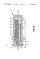
- FIG. 2 shows a transducer with two serial pressure cylinders (a) for the elongation of a fiber Bragg grating, or (b) for the oppositely directed elongation of two fiber Bragg gratings;
- FIGS. 3 ( a ), ( b ) show a transducer with two parallel pressure cylinders for the elongation of a fiber Bragg grating
- FIG. 4 shows a transducer with two pressure cylinders for a separate elongation of two fiber Bragg gratings for the purpose of measuring two absolute pressures
- FIG. 5 shows a multiplex arrangement with a plurality of differential pressure sensors in reflection
- FIG. 6 shows a venturi tube with differential pressure sensor for the purpose of determining flow rates.
- the subject matter of the invention is a fiber-optic pressure sensor.
- the known measuring principle consists in that a fiber Bragg grating which is written into a monomode fiber by UV light acts as a reflection or transmission filter with a characteristic Bragg wavelength ⁇ B . Longitudinal fiber elongations change the grating period and refractive index and displace the Brag wavelength ⁇ B .
- the output signals are wavelength-coded and independent of the light power.
- the measuring range is limited only by the fiber ultimate strength in the case of elongation measurements with the aid of Bragg gratings.
- the fiber-optic pressure sensor 1 , 25 comprises a transducer 1 with a sensor fiber 2 which has at least one fiber Bragg grating 3 , 4 , 5 , comprising at least one first pressure member 7 a for holding a first medium 11 a under an all round pressure p 1 , comprising at least one second pressure member 7 b for holding a second medium 11 b under an all round pressure p 2 , and being configured for measuring a pressure difference p 1 -p 2 by converting the all round pressures p 1 , p 2 into a longitudinal elongation or compression of at least one fiber Bragg grating 3 , 4 of the sensor fiber 3 .
- the transducer is advantageously configured for a differential elongation of the fiber Bragg grating 3 , 4 induced by the pressure difference p 1 -p 2 .
- the sensor 1 , 25 is suitable for measuring differential pressures and flow rates in oil drill holes.
- the sensor fiber 2 is mounted between holders 6 a , 6 b , 6 c ; 15 b and preferably prestressed, the holders 6 a , 6 b , 6 c ; 15 b are connected in a force-closed fashion to the pressure members 7 a , 7 b and, if appropriate, to supporting members 15 a , and the pressure members 7 a , 7 b are configured to deflect at least one holder 6 a , 6 b , 6 c as a function of the pressures p 1 , p 2 ,
- exactly two cylindrical pressure members 7 a , 7 b are provided, which are arranged concentrically, in parallel or serially relative to one another, the pressure cylinders 7 a , 7 b have the same length L and the holders 6 a , 6 b , 6 c are fastened on plunger faces 8 , 8 a , 8 b of the pressure cylinders 7 a , 7 b
- the transducer 1 is to have separate inlets 10 a , 10 b for the media 11 a 11 b into the pressure members 7 a , 7 b .
- a fiber Bragg grating 3 can be provided for differential pressure measurement, a fiber Bragg grating 4 can be provided for error compensation, and/or a fiber Bragg grating 5 can be provided for temperature measurement.
- 3 is always, 4 is sometimes and 5 is not mechanically prestressed. They are characterized by different Bragg wavelengths ⁇ B and can be read out spectrally in a separate fashion.
- the transducer 1 has pressure-tight fiber bushings 12 a , 12 b for the sensor fiber 2 and/or a cavity 13 for a fiber Bragg grating 5 for the purpose of temperature measurement. At least one block with a bore for lateral support of the sensor fiber 2 in the region of a fiber Bragg grating 3 , 4 is to be provided for a compression arrangement (not illustrated). A very much larger pressure measuring range can be realized because glass fibers can be loaded 20 times more in terms of pressure than elongation.
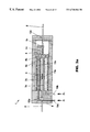
- FIGS. 1 and 3 show arrangements in which a fiber Bragg grating 3 is fixed for the purpose of differential pressure measurement by holders 6 a , 6 b between the first and second pressure member 7 a , 7 b .
- an error compensation fiber Bragg grating 4 can be fastened, between holders 6 a , 6 c , in reverse sequence between the second and first pressure members 7 b , 7 a .
- the sensor fiber sections with the fiber Bragg gratings 3 , 4 are arranged on both sides of the end plate or plunger face 8 of the first pressure cylinder 7 a and are connected at their opposite ends to the second pressure cylinder 7 b .
- elongations owing to differential pressures p 1 -p 2 are opposed to one another, and interfering elongations owing to isotropic pressure, temperature dependencies of the fiber Bragg gratings 3 , 4 and thermal expansion of the pressure members 7 a , 7 b are rendered codirectional. It is therefore possible to eliminate the interference signals and double the useful signal by forming a difference signal between the first and second fiber Bragg grating 3 , 4 .
- FIG. 2 show arrangements in which a fiber Bragg grating 3 is mounted, on holders 6 a , 15 b , between a holder 6 a , which can be deflected by differential pressure between two pressure members 7 a , 7 b , and a supporting member 15 a , which is permanently connected to the transducer housing 9 .
- the pressure members 7 a , 7 b are preferably arranged serially one behind another and have a common end plate 8 by which the holder 6 a is connected.
- FIG. 1 shows arrangements in which a fiber Bragg grating 3 is mounted, on holders 6 a , 15 b , between a holder 6 a , which can be deflected by differential pressure between two pressure members 7 a , 7 b , and a supporting member 15 a , which is permanently connected to the transducer housing 9 .
- the pressure members 7 a , 7 b are preferably arranged serially one behind another and have a common end plate 8 by which the
- a prestressed error compensation fiber Bragg grating 4 is held ( 6 a , 15 b ) for the purpose of antiphasal change in elongation in reverse sequence between the supporting members 15 a and the holder 6 a which can be deflected by differential pressure. That is to say, the fiber Bragg gratings 3 and 4 are connected on both sides of the holder 6 a to the substantially fixed supporting member 15 a via the holders 15 b .
- the above discussed compensation according to the invention of interference effects in the differential signal can be achieved, in turn, thereby.
- the first pressure cylinder 7 a is mounted on a projection or base 14 , is sealed at the other end by an end plate 8 a and subjected to an internal pressure p 1 and an external pressure p 2
- the concentric second pressure member 7 b is mounted on the housing 9 , has an open end plate 8 b and is exposed to the second pressure p 2 inside and outside via the inlet 10 b .
- L denotes the length of the pressure cylinder 7 a , 7 b
- l denotes the length of the elongation length of the sensor fiber 2 and the length of the base 14 .
- a variant with parallel pressure members 7 a , 7 b is shown in FIG. 3 b.
- the differential longitudinal elongation L of the pressure members 7 a , 7 b depends on the pressure-induced longitudinal stresses and also, via the Poisson transverse elongation, on the radial and tangential stresses in two pressure members 7 a , 7 b .
- the result for pressure members 7 a , 7 b of equal length L, equal modulus of elasticity E and equal Poisson number ⁇ is
- the differential elongation L does not depend on the absolute pressures p 1 , p 2 or on the radii of the pressure members 7 b .
- L is transferred onto the fiber elongation distance l and effects a wavelength displacement of
- the prestressing is to be dimensioned such that it does not vanish even in the case of maximum pressure loading.
- the magnitude of the fiber elongation can be prescribed for a given transducer elongation and can, in particular, be selected as large for a high pressure resolution.
- the radii of the second pressure member 7 b are non-critical and can be 6 mm and 8 mm, for example.
- a transducer housing 9 with an inside radius of 7.5 mm and an outside radius of 10.5 mm can withstand absolute pressures above 100 MPa.
- a second fiber Bragg grating 4 which can be read out spectrally in a separate fashion, is exposed on an elongation distance l of the same length to the same pressure p 2 , the same temperature and the same thermal elongation, and the noise-free difference signal of the two fiber Bragg gratings 3 , 4 is evaluated.
- the temperature of the transducer 1 can be monitored, by means of a third, mechanically unloaded fiber Bragg grating 5 and, if appropriate, be used to correct a differential pressure signal.
- At least one pressure member 7 a , 7 b and/or at least one supporting member 15 a is to consist of or be assembled from materials with different coefficients of thermal expansion ⁇ 1 , ⁇ 2 , such that a differential thermal expansion between the holders 6 a , 6 b , 6 c counteracts a thermally induced displacement of a Bragg wavelength ⁇ B of the sensor fiber 2 . It holds in the case of complete temperature compensation that
- ⁇ 1 , ⁇ 2 being the coefficient of thermal expansion of the first pressure member 7 a (including the base 14 ), and of the second pressure member 7 b .
- the fiber prestressing is to be selected high enough to ensure adequate prestressing even in the case of maximum operating temperature and maximum pressure difference p 2 -p 1 . The reliability of the differential pressure measurement is clearly improved by the temperature compensation.
- the pressure or supporting members 7 a , 7 b , 15 a can be assembled from at least two segments with different coefficients of thermal expansion and prescribable lengths L′, L′′.
- the second cylinder 7 b is constructed from segments L′′ with ⁇ 1 and L′ with ⁇ 2 .
- the modified condition for the temperature compensation runs
- An advantage of the temperature-compensated arrangement according to FIG. 1 b consists in that only the first fiber Bragg grating 3 is mechanically prestressed. Interference owing to isotropic pressure p 2 is detected with the aid of the now unloaded fiber Bragg grating 4 and the temperature dependence of the latter is corrected with the aid of the fiber Bragg grating 5 .
- the passive temperature compensation in accordance with FIG. 1 b reduces the Bragg wavelength spectral region required for a fiber sensor 1 . It can be applied in principle in the case of all exemplary embodiments.
- FIGS. 2 a , 2 b and 3 a have the advantage that the fiber Bragg gratings 3 , 4 , 5 are not exposed to the pressure of the medium 11 b .
- the interior of the transducer 1 outside the pressure members 7 a , 7 b can be filled with a vacuum or a low-pressure gas.
- the pressure members 7 a , 7 b are to be designed for the full pressure loading p 1 or p 2 .
- the measuring range for differential pressures then extends up to p 1 or p 2 .
- 3 a shows a variant with two parallel pressure members 7 a , 7 b , which are loaded exclusively by internal pressure p 1 or p 2 , a prestressed fiber Bragg grating 3 for differential pressure measurement, and an unloaded fiber Bragg grating 5 for temperature measurement.
- the fiber Bragg grating 3 is held 6 a , 6 b between cylinders 7 a , 7 b of equal length via an end place 8 a and an end plate 8 b lengthened by the base 14 of length l.
- the compact arrangement of two absolute pressure measurements in a transducer 1 is advantageous in this case.
- FIG. 5 shows a multiplex arrangement 25 with a plurality of transducers 1 , according to the invention, of different Bragg wavelengths O B .
- the transducers 1 are optically connected to a broadband light source 16 , for example an LED or SLD and, preferably via a fiber coupler 18 , to a wavelength-division demultiplexer 19 and a detector plus an electronic measuring system 20 (and computer 21 ).
- 22 denotes an optional source of reference wavelengths for spectral calibration of the fiber Bragg gratings 3 , 4 , 5 .
- the gratings have a spectral width of approximately 0.2 nm, a maximum reflectivity of 90%, a length of 10 mm and tuning ranges of 2.4 nm for temperature (0° C.-230° C.) and 3.6 nm for differential pressure measurement (0.003 maximum elongation).
- a passive temperature-compensated transducer 1 With a 1 nm standby spacing relative to the tuning range of the adjacent grating, a passive temperature-compensated transducer 1 therefore requires a 7 nm spectral width.
- 7 transducers 1 can be multiplexed by wavelength with a low loss 1550 nm light source (50 nm spectral width). Alternatively, or in addition, the transducers 1 can also be read out sequentially one after another using a time-division multiplexing method and/or by means of fiber-optic switches.
- FIG. 6 shows one use of a fiber-optic differential pressure sensor 1 , 25 according to the invention, in the case of which a flow rate v 1 of a fluid flow 24 is determined from a differential pressure measurement.
- the inlets 10 a , 10 b of the transducer 1 are connected to a venturi tube 23 at two locations with cross-sectional areas A 1 and A 2 .
- the fiber-optic pressure sensor 1 , 25 is characterized overall by an advantageous interaction between transducer 1 , which can be exposed to extreme pressure loads, and the fiber Bragg grating 3 , 4 , which is very sensitive to elongation, of the sensor fiber 2 . It is possible as a result to measure differential pressures of between 0.1 kPa and 10 MPa at very high absolute pressures of up to approximately 100 MPa with high resolution. A further advantage consists in that the pressure signal is wavelength-coded, and thus very insensitive to interference. It can be read out directly using fiber optics over large distances between the passive sensor head 1 and the optoelectronic measuring device 16 , 19 - 22 . Also advantageous are the good high-temperature capability, corrosion resistance and insensitivity to electromagnetic interference. Because of its compactness, the sensor 1 , 25 is particularly suitable for measuring differential pressures and flow rates in drill holes.
- Fiber optic differential pressure sensor (transducer) 2 Optical fiber, sensor fiber 3 Fiber Bragg grating 1 (for pressure measurement) 4 Fiber Bragg grating 2 (for compensation measurement) 5 Fiber Bragg grating 3 (for temperature measurement) 6a-6c,15b Holders, fiber holders, ferrule holders 7a-7b Pressure members, pressure cylinders 7a Pressure cylinder 1 (internal pressure p i ) 7b Pressure cylinder 2 (reference pressure p 2 ), reference cylinder 8, 8a, 8b End plates of the pressure members, plunger face 9 Transducer housing 10a, 10b Inlets 11a Medium 1, fluid 1 (under pressure p 1 ) 11b Medium 2, fluid 2 (under pressure p 2 ) 12a, 12b Pressure-tight fiber bushings 13 Cavity for temperature sensor fiber 14 Projection, base 15a Supporting member, supporting cylinder 16 (Broadband) light source, LED, SLD 17 Feeder fibers 18 Coupler, fiber coupler 19 Wavelength-division demultiplexer, tunable spectral filter
Abstract
Description
| 1 | Fiber optic differential pressure sensor | ||
| (transducer) | |||
| 2 | Optical fiber, sensor fiber | ||
| 3 | Fiber Bragg grating 1 (for pressure | ||
| measurement) | |||
| 4 | Fiber Bragg grating 2 (for compensation | ||
| measurement) | |||
| 5 | Fiber Bragg grating 3 (for temperature | ||
| measurement) | |||
| 6a-6c,15b | Holders, fiber holders, ferrule holders | ||
| 7a-7b | Pressure members, pressure cylinders | ||
| 7a | Pressure cylinder 1 (internal pressure pi) | ||
| 7b | Pressure cylinder 2 (reference pressure p2), | ||
| reference cylinder | |||
| 8, 8a, 8b | End plates of the pressure members, plunger | ||
| face | |||
| 9 | Transducer housing | ||
| 10a, 10b | Inlets | ||
| 11a | Medium 1, fluid 1 (under pressure p1) | ||
| 11b | Medium 2, fluid 2 (under pressure p2) | ||
| 12a, 12b | Pressure-tight fiber bushings | ||
| 13 | Cavity for temperature sensor fiber | ||
| 14 | Projection, base | ||
| 15a | Supporting member, supporting cylinder | ||
| 16 | (Broadband) light source, LED, SLD | ||
| 17 | Feeder fibers | ||
| 18 | Coupler, fiber coupler | ||
| 19 | Wavelength-division demultiplexer, tunable | ||
| spectral filter, Fabry-Perot filter | |||
| 20 | Detector and electronic measuring system | ||
| 21 | Computer, PC | ||
| 22 | Source for reference wavelengths | ||
| 23 | Venturi tube | ||
| 24 | Fluid flow | ||
| 25 | Overall sensor | ||
| A1, A2 | Cross-sectional surfaces | ||
| α1, α2 | Coefficients of thermal expansion | ||
| Ε | Young's modulus of elasticity | ||
| l | Length of the elongation distance of the | ||
| pressure sensor fiber | |||
| L | Length of a pressure cylinder | ||
| ΔL | Differential elongation | ||
| L′, L″ | Segment lengths of a pressure | ||
| cylinder/supporting cylinder | |||
| λB | Bragg wavelength | ||
| ΔλB | Bragg wavelength displacement | ||
| μ | Poisson number | ||
| p1, p2 | Pressures | ||
| Δp | Pressure difference | ||
| Ri | Inside radius of the first pressure cylinder | ||
| Ra | Outside radius of the first pressure cylinder | ||
| v1, v2 | Flow rates | ||
Claims (21)
Applications Claiming Priority (3)
| Application Number | Priority Date | Filing Date | Title |
|---|---|---|---|
| DE19860409A DE19860409A1 (en) | 1998-12-28 | 1998-12-28 | Fiber Bragg grating sensor for measuring differential pressures and flow velocities |
| DE19860409 | 1998-12-28 | ||
| PCT/CH1999/000608 WO2000039553A1 (en) | 1998-12-28 | 1999-12-16 | Fibre bragg-grating sensor |
Publications (1)
| Publication Number | Publication Date |
|---|---|
| US6740866B1 true US6740866B1 (en) | 2004-05-25 |
Family
ID=7892908
Family Applications (1)
| Application Number | Title | Priority Date | Filing Date |
|---|---|---|---|
| US09/868,188 Expired - Lifetime US6740866B1 (en) | 1998-12-28 | 1999-12-16 | Fibre Bragg-grating sensor |
Country Status (7)
| Country | Link |
|---|---|
| US (1) | US6740866B1 (en) |
| EP (1) | EP1147390A1 (en) |
| AU (1) | AU1502600A (en) |
| BR (1) | BR9916623A (en) |
| DE (1) | DE19860409A1 (en) |
| NO (1) | NO20013152L (en) |
| WO (1) | WO2000039553A1 (en) |
Cited By (18)
| Publication number | Priority date | Publication date | Assignee | Title |
|---|---|---|---|---|
| US20030034768A1 (en) * | 2001-08-17 | 2003-02-20 | Siemens Aktiengesellschaft | Method and device for compensating for interfering variables in an optical sensor |
| US20040074307A1 (en) * | 2000-12-07 | 2004-04-22 | Tjin Swee Chuan | Fiber optic force sensor |
| US20040114849A1 (en) * | 2002-12-16 | 2004-06-17 | Schlumberger Technology Corporation | Multiple mode pre-loadable fiber optic pressure and temperature sensor |
| US20050274194A1 (en) * | 2004-06-15 | 2005-12-15 | Skinner Neal G | Fiber optic differential pressure sensor |
| US20060011820A1 (en) * | 2004-07-16 | 2006-01-19 | Kin-Man Yip And Chow-Shing Shin | Fiber-optic sensing system |
| US20080095612A1 (en) * | 2004-04-27 | 2008-04-24 | Paul Girbig | Method And Regulation System For Monitoring A Compressor Of A Gas Turbine In Particular |
| US20080156971A1 (en) * | 2004-12-15 | 2008-07-03 | Toshimichi Ogisu | Modular sensor for damage detection, manufacturing method, and structural composite material |
| CN100417963C (en) * | 2006-10-27 | 2008-09-10 | 东南大学 | Distributed long gauge length optical fibre Bragg optical grating strain sensor and mfg. process thereof |
| US20090210168A1 (en) * | 2006-09-08 | 2009-08-20 | Vincelette Andre | Optical Device for Measuring a Physical Parameter in a Hydrogen Contaminated Sensing Zone |
| US20100142880A1 (en) * | 2008-12-05 | 2010-06-10 | General Electric Company | Fiber optic sensing system |
| US20100307256A1 (en) * | 2009-06-05 | 2010-12-09 | Baker Hughes Incorporated | Sensory transducer and method |
| US20110191031A1 (en) * | 2010-01-29 | 2011-08-04 | Baker Hughes Incorporated | Device and method for discrete distributed optical fiber pressure sensing |
| US20110229071A1 (en) * | 2009-04-22 | 2011-09-22 | Lxdata Inc. | Pressure sensor arrangement using an optical fiber and methodologies for performing an analysis of a subterranean formation |
| US8139905B1 (en) * | 2010-10-08 | 2012-03-20 | Michael Louis Bazzone | Generator protection system |
| US9717422B2 (en) | 2012-12-12 | 2017-08-01 | Volcano Corporation | Sheath with optically interrogatable sensors |
| US10151681B2 (en) | 2017-03-27 | 2018-12-11 | The United States Of America, As Represented By The Secretary Of Commerce | Optofluidic flow meter |
| US10283821B2 (en) | 2014-09-29 | 2019-05-07 | Fraunhofer-Gesellschaft Zur Forderung Der Angewandten Forschung E.V. | Battery and method for operating same |
| US10782199B2 (en) | 2015-12-11 | 2020-09-22 | Optics11 B.V. | Pressure sensor and sensor system comprising one or more pressure sensors |
Families Citing this family (4)
| Publication number | Priority date | Publication date | Assignee | Title |
|---|---|---|---|---|
| US6650799B2 (en) * | 2001-09-18 | 2003-11-18 | Hampton University | Apparatus for and methods of sensing evanescent events in a fluid field |
| FR2841982B1 (en) | 2002-07-03 | 2005-03-25 | Inst Francais Du Petrole | FIBER OPTIC PRESSURE SENSOR COMPENSATED IN TEMPERATURE |
| US7017417B2 (en) * | 2004-02-10 | 2006-03-28 | Weatherford/Lamb, Inc. | Pressure sensor assembly suitable for use in harsh environments |
| BRPI0804823B1 (en) * | 2008-11-05 | 2018-09-11 | Surco Tecnologia Industrial Ltda. | dual temperature and pressure and flow optical measurement equipment |
Citations (10)
| Publication number | Priority date | Publication date | Assignee | Title |
|---|---|---|---|---|
| DE873304C (en) | 1944-02-01 | 1953-04-13 | Johannes Dipl-Ing Schoen | Square root flow integrator |
| WO1985004473A1 (en) | 1984-03-31 | 1985-10-10 | Kent Scientific And Industrial Projects Limited | Optical pressure sensing apparatus |
| US4761073A (en) | 1984-08-13 | 1988-08-02 | United Technologies Corporation | Distributed, spatially resolving optical fiber strain gauge |
| US5042898A (en) | 1989-12-26 | 1991-08-27 | United Technologies Corporation | Incorporated Bragg filter temperature compensated optical waveguide device |
| EP0466623A1 (en) | 1990-07-09 | 1992-01-15 | IWKA Aktiengesellschaft | Fiber-optic pressure transducer with temperature compensation |
| US5113070A (en) | 1991-03-29 | 1992-05-12 | Abb Vetco Gray Inc. | Temperature compensator for an optic fiber pressure transducer |
| EP0713077A1 (en) | 1994-11-17 | 1996-05-22 | Alcatel Cable | Detection and/or measurement procedure for physical entities using a distributed sensor |
| DE19648403C1 (en) | 1996-11-22 | 1998-04-02 | Thomas Dr Ing Nagel | Direct pressure and-or tensional forces detector |
| US6304686B1 (en) * | 2000-02-09 | 2001-10-16 | Schlumberger Technology Corporation | Methods and apparatus for measuring differential pressure with fiber optic sensor systems |
| US6490931B1 (en) * | 1998-12-04 | 2002-12-10 | Weatherford/Lamb, Inc. | Fused tension-based fiber grating pressure sensor |
-
1998
- 1998-12-28 DE DE19860409A patent/DE19860409A1/en not_active Withdrawn
-
1999
- 1999-12-16 BR BR9916623-2A patent/BR9916623A/en not_active IP Right Cessation
- 1999-12-16 EP EP99957245A patent/EP1147390A1/en not_active Withdrawn
- 1999-12-16 US US09/868,188 patent/US6740866B1/en not_active Expired - Lifetime
- 1999-12-16 WO PCT/CH1999/000608 patent/WO2000039553A1/en not_active Application Discontinuation
- 1999-12-16 AU AU15026/00A patent/AU1502600A/en not_active Abandoned
-
2001
- 2001-06-22 NO NO20013152A patent/NO20013152L/en not_active Application Discontinuation
Patent Citations (10)
| Publication number | Priority date | Publication date | Assignee | Title |
|---|---|---|---|---|
| DE873304C (en) | 1944-02-01 | 1953-04-13 | Johannes Dipl-Ing Schoen | Square root flow integrator |
| WO1985004473A1 (en) | 1984-03-31 | 1985-10-10 | Kent Scientific And Industrial Projects Limited | Optical pressure sensing apparatus |
| US4761073A (en) | 1984-08-13 | 1988-08-02 | United Technologies Corporation | Distributed, spatially resolving optical fiber strain gauge |
| US5042898A (en) | 1989-12-26 | 1991-08-27 | United Technologies Corporation | Incorporated Bragg filter temperature compensated optical waveguide device |
| EP0466623A1 (en) | 1990-07-09 | 1992-01-15 | IWKA Aktiengesellschaft | Fiber-optic pressure transducer with temperature compensation |
| US5113070A (en) | 1991-03-29 | 1992-05-12 | Abb Vetco Gray Inc. | Temperature compensator for an optic fiber pressure transducer |
| EP0713077A1 (en) | 1994-11-17 | 1996-05-22 | Alcatel Cable | Detection and/or measurement procedure for physical entities using a distributed sensor |
| DE19648403C1 (en) | 1996-11-22 | 1998-04-02 | Thomas Dr Ing Nagel | Direct pressure and-or tensional forces detector |
| US6490931B1 (en) * | 1998-12-04 | 2002-12-10 | Weatherford/Lamb, Inc. | Fused tension-based fiber grating pressure sensor |
| US6304686B1 (en) * | 2000-02-09 | 2001-10-16 | Schlumberger Technology Corporation | Methods and apparatus for measuring differential pressure with fiber optic sensor systems |
Non-Patent Citations (1)
| Title |
|---|
| "Optical In-Fibre Grating high Pressure Sensor", Xu, et al., Electronics Letters, vol. 29, No. 4, Feb. 18, 1993, pp. 398-399. |
Cited By (34)
| Publication number | Priority date | Publication date | Assignee | Title |
|---|---|---|---|---|
| US20040074307A1 (en) * | 2000-12-07 | 2004-04-22 | Tjin Swee Chuan | Fiber optic force sensor |
| US7027672B2 (en) * | 2000-12-07 | 2006-04-11 | Ntu Ventures Private Limited | Fiber optic force sensor |
| US20030034768A1 (en) * | 2001-08-17 | 2003-02-20 | Siemens Aktiengesellschaft | Method and device for compensating for interfering variables in an optical sensor |
| US7064315B2 (en) * | 2001-08-17 | 2006-06-20 | Siemens Aktiengesellschaft | Method and device for compensating for interfering variables in an optical sensor |
| US20040114849A1 (en) * | 2002-12-16 | 2004-06-17 | Schlumberger Technology Corporation | Multiple mode pre-loadable fiber optic pressure and temperature sensor |
| US6898339B2 (en) * | 2002-12-16 | 2005-05-24 | Schlumberger Technology Corporation | Multiple mode pre-loadable fiber optic pressure and temperature sensor |
| US8297835B2 (en) * | 2004-04-27 | 2012-10-30 | Siemens Aktiengesellschaft | Method and regulation system for monitoring a compressor of a gas turbine in particular |
| US20080095612A1 (en) * | 2004-04-27 | 2008-04-24 | Paul Girbig | Method And Regulation System For Monitoring A Compressor Of A Gas Turbine In Particular |
| US7159468B2 (en) * | 2004-06-15 | 2007-01-09 | Halliburton Energy Services, Inc. | Fiber optic differential pressure sensor |
| US20070068262A1 (en) * | 2004-06-15 | 2007-03-29 | Skinner Neal G | Fiber Optic Differential Pressure Sensor |
| US7458273B2 (en) | 2004-06-15 | 2008-12-02 | Welldynamics, B.V. | Fiber optic differential pressure sensor |
| US20050274194A1 (en) * | 2004-06-15 | 2005-12-15 | Skinner Neal G | Fiber optic differential pressure sensor |
| US7196318B2 (en) * | 2004-07-16 | 2007-03-27 | Kin-Man Yip | Fiber-optic sensing system |
| US20060011820A1 (en) * | 2004-07-16 | 2006-01-19 | Kin-Man Yip And Chow-Shing Shin | Fiber-optic sensing system |
| US20080156971A1 (en) * | 2004-12-15 | 2008-07-03 | Toshimichi Ogisu | Modular sensor for damage detection, manufacturing method, and structural composite material |
| US7405391B2 (en) * | 2004-12-15 | 2008-07-29 | Fuji Jukogyo Kabushiki Kaisha | Modular sensor for damage detection, manufacturing method, and structural composite material |
| US20090210168A1 (en) * | 2006-09-08 | 2009-08-20 | Vincelette Andre | Optical Device for Measuring a Physical Parameter in a Hydrogen Contaminated Sensing Zone |
| US10400579B2 (en) * | 2006-09-08 | 2019-09-03 | Weatherford Canada Ltd. | Optical device for measuring a physical parameter in a hydrogen contaminated sensing zone |
| CN100417963C (en) * | 2006-10-27 | 2008-09-10 | 东南大学 | Distributed long gauge length optical fibre Bragg optical grating strain sensor and mfg. process thereof |
| US20100142880A1 (en) * | 2008-12-05 | 2010-06-10 | General Electric Company | Fiber optic sensing system |
| US8135245B2 (en) | 2008-12-05 | 2012-03-13 | General Electric Company | Fiber optic sensing system |
| US20110229071A1 (en) * | 2009-04-22 | 2011-09-22 | Lxdata Inc. | Pressure sensor arrangement using an optical fiber and methodologies for performing an analysis of a subterranean formation |
| US9347312B2 (en) | 2009-04-22 | 2016-05-24 | Weatherford Canada Partnership | Pressure sensor arrangement using an optical fiber and methodologies for performing an analysis of a subterranean formation |
| US10246989B2 (en) | 2009-04-22 | 2019-04-02 | Weatherford Technology Holdings, Llc | Pressure sensor arrangement using an optical fiber and methodologies for performing an analysis of a subterranean formation |
| US10837274B2 (en) | 2009-04-22 | 2020-11-17 | Weatherford Canada Ltd. | Pressure sensor arrangement using an optical fiber and methodologies for performing an analysis of a subterranean formation |
| US7958785B2 (en) | 2009-06-05 | 2011-06-14 | Baker Hughes Incorporated | Sensory transducer and method |
| US20100307256A1 (en) * | 2009-06-05 | 2010-12-09 | Baker Hughes Incorporated | Sensory transducer and method |
| US20110191031A1 (en) * | 2010-01-29 | 2011-08-04 | Baker Hughes Incorporated | Device and method for discrete distributed optical fiber pressure sensing |
| US9476294B2 (en) | 2010-01-29 | 2016-10-25 | Baker Hughes Incorporated | Device and method for discrete distributed optical fiber pressure sensing |
| US8139905B1 (en) * | 2010-10-08 | 2012-03-20 | Michael Louis Bazzone | Generator protection system |
| US9717422B2 (en) | 2012-12-12 | 2017-08-01 | Volcano Corporation | Sheath with optically interrogatable sensors |
| US10283821B2 (en) | 2014-09-29 | 2019-05-07 | Fraunhofer-Gesellschaft Zur Forderung Der Angewandten Forschung E.V. | Battery and method for operating same |
| US10782199B2 (en) | 2015-12-11 | 2020-09-22 | Optics11 B.V. | Pressure sensor and sensor system comprising one or more pressure sensors |
| US10151681B2 (en) | 2017-03-27 | 2018-12-11 | The United States Of America, As Represented By The Secretary Of Commerce | Optofluidic flow meter |
Also Published As
| Publication number | Publication date |
|---|---|
| AU1502600A (en) | 2000-07-31 |
| EP1147390A1 (en) | 2001-10-24 |
| WO2000039553A1 (en) | 2000-07-06 |
| DE19860409A1 (en) | 2000-06-29 |
| BR9916623A (en) | 2001-09-25 |
| NO20013152D0 (en) | 2001-06-22 |
| NO20013152L (en) | 2001-06-22 |
Similar Documents
| Publication | Publication Date | Title |
|---|---|---|
| US6740866B1 (en) | Fibre Bragg-grating sensor | |
| US6563970B1 (en) | Pressure sensor with fibre-integrated bragg grating, comprising an integrated temperature sensor with fibre-integrated bragg grating | |
| US5844667A (en) | Fiber optic pressure sensor with passive temperature compensation | |
| US5877426A (en) | Bourdon tube pressure gauge with integral optical strain sensors for measuring tension or compressive strain | |
| US7423762B2 (en) | Rugged fabry-perot pressure sensor | |
| CA2353567C (en) | Bragg grating pressure sensor | |
| US6671055B1 (en) | Interferometric sensors utilizing bulk sensing mediums extrinsic to the input/output optical fiber | |
| US6450037B1 (en) | Non-intrusive fiber optic pressure sensor for measuring unsteady pressures within a pipe | |
| US6597821B1 (en) | Fiber laser sensor for measuring differential pressures and flow velocities | |
| US20040202400A1 (en) | System and method for measuring physical stimuli using vertical cavity surface emitting lasers with integrated tuning means | |
| US5196694A (en) | Temperature compensated self-referenced fiber optic microbend pressure transducer | |
| EP1017975B1 (en) | Pressure sensor | |
| GB2409267A (en) | Pressure sensor with temperature compensated optical fiber | |
| US6744035B2 (en) | Passive, temperature compensated techniques for tunable filter calibration in bragg-grating interrogation systems | |
| JP4403674B2 (en) | Optical fiber sensor | |
| Rao et al. | Temperature-strain discrimination using a wavelength-division-multiplexed chirped in-fibre-Bragg-grating/extrinsic Fabry-Pérot sensor system | |
| US20060008196A1 (en) | Bragg grating pressure sensor | |
| EP2537014B1 (en) | Fluid pressure monitoring apparatus | |
| Yamate et al. | Transversely loaded Bragg grating pressure transducer with mechanically enhancing the sensitivity | |
| RU2113697C1 (en) | Optical pressure gauge | |
| Pashaie | Simultaneous Measurement of Temperature and Strain Based on Peak Power Changes and Wavelength Shift Using Only One Uniform Fiber Bragg Grating | |
| WO2021246907A1 (en) | Sensitive element of pressure sensor | |
| Wlodarczyk et al. | Fiber optic pressure sensor for combustion monitoring and control | |
| Peng et al. | Cubic-zirconia-based fiber optic pressure sensor for high-temperature environment | |
| Latifi et al. | High pressure measurement by optical fiber fabry-perot sensor for downhole application |
Legal Events
| Date | Code | Title | Description |
|---|---|---|---|
| AS | Assignment |
Owner name: ABB RESEARCH LTD, SWITZERLAND Free format text: ASSIGNMENT OF ASSIGNORS INTEREST;ASSIGNORS:BOHNERT, KLAUS;BRANDLE, HUBERT;REEL/FRAME:014120/0829 Effective date: 20010613 |
|
| AS | Assignment |
Owner name: ABB RESEARCH LTD., SWITZERLAND Free format text: ASSIGNMENT OF ASSIGNORS INTEREST;ASSIGNORS:BOHNERT, KLAUS;BRANDLE, HUBERT;REEL/FRAME:014500/0890 Effective date: 20010613 |
|
| STCF | Information on status: patent grant |
Free format text: PATENTED CASE |
|
| AS | Assignment |
Owner name: J.P. MORGAN EUROPE LIMITED, AS SECURITY AGENT, UNI Free format text: SECURITY AGREEMENT;ASSIGNOR:ABB OFFSHORE SYSTEMS INC.;REEL/FRAME:015215/0872 Effective date: 20040712 |
|
| AS | Assignment |
Owner name: VETCO GRAY CONTROLS LIMITED, UNITED KINGDOM Free format text: CHANGE OF NAME;ASSIGNOR:ABB OFFSHORE SYSTEMS LIMITED;REEL/FRAME:015428/0865 Effective date: 20040730 Owner name: ABB OFFSHORE SYSTEMS LIMITED, UNITED KINGDOM Free format text: ASSIGNMENT OF ASSIGNORS INTEREST;ASSIGNOR:ABB RESEARCH LIMITED;REEL/FRAME:015428/0889 Effective date: 20040713 |
|
| AS | Assignment |
Owner name: VETCO GRAY CONTROLS INC. (ABB OFFSHORE SYSTEMS INC Free format text: GLOBAL DEED OF RELEASE;ASSIGNOR:J.P. MORGAN EUROPE LIMITED;REEL/FRAME:019795/0479 Effective date: 20070223 |
|
| FPAY | Fee payment |
Year of fee payment: 4 |
|
| FPAY | Fee payment |
Year of fee payment: 8 |
|
| AS | Assignment |
Owner name: GE OIL & GAS UK LIMITED, UNITED KINGDOM Free format text: ASSIGNMENT OF ASSIGNORS INTEREST;ASSIGNOR:VETCO GRAY CONTROLS LIMITED;REEL/FRAME:035316/0821 Effective date: 20150224 |
|
| FPAY | Fee payment |
Year of fee payment: 12 |