US6256374B1 - Miniature C-arm apparatus with dual video display monitor and single driver interface therefor - Google Patents
Miniature C-arm apparatus with dual video display monitor and single driver interface therefor Download PDFInfo
- Publication number
- US6256374B1 US6256374B1 US09/419,593 US41959399A US6256374B1 US 6256374 B1 US6256374 B1 US 6256374B1 US 41959399 A US41959399 A US 41959399A US 6256374 B1 US6256374 B1 US 6256374B1
- Authority
- US
- United States
- Prior art keywords
- displays
- arm
- ray
- imaging system
- fluoroscopic imaging
- Prior art date
- Legal status (The legal status is an assumption and is not a legal conclusion. Google has not performed a legal analysis and makes no representation as to the accuracy of the status listed.)
- Expired - Lifetime
Links
Images


Classifications
-
- A—HUMAN NECESSITIES
- A61—MEDICAL OR VETERINARY SCIENCE; HYGIENE
- A61B—DIAGNOSIS; SURGERY; IDENTIFICATION
- A61B6/00—Apparatus for radiation diagnosis, e.g. combined with radiation therapy equipment
- A61B6/44—Constructional features of apparatus for radiation diagnosis
- A61B6/4429—Constructional features of apparatus for radiation diagnosis related to the mounting of source units and detector units
- A61B6/4435—Constructional features of apparatus for radiation diagnosis related to the mounting of source units and detector units the source unit and the detector unit being coupled by a rigid structure
- A61B6/4441—Constructional features of apparatus for radiation diagnosis related to the mounting of source units and detector units the source unit and the detector unit being coupled by a rigid structure the rigid structure being a C-arm or U-arm
-
- A—HUMAN NECESSITIES
- A61—MEDICAL OR VETERINARY SCIENCE; HYGIENE
- A61B—DIAGNOSIS; SURGERY; IDENTIFICATION
- A61B6/00—Apparatus for radiation diagnosis, e.g. combined with radiation therapy equipment
- A61B6/46—Apparatus for radiation diagnosis, e.g. combined with radiation therapy equipment with special arrangements for interfacing with the operator or the patient
- A61B6/461—Displaying means of special interest
- A61B6/464—Displaying means of special interest involving a plurality of displays
-
- A—HUMAN NECESSITIES
- A61—MEDICAL OR VETERINARY SCIENCE; HYGIENE
- A61B—DIAGNOSIS; SURGERY; IDENTIFICATION
- A61B6/00—Apparatus for radiation diagnosis, e.g. combined with radiation therapy equipment
- A61B6/44—Constructional features of apparatus for radiation diagnosis
- A61B6/4405—Constructional features of apparatus for radiation diagnosis the apparatus being movable or portable, e.g. handheld or mounted on a trolley
-
- A—HUMAN NECESSITIES
- A61—MEDICAL OR VETERINARY SCIENCE; HYGIENE
- A61B—DIAGNOSIS; SURGERY; IDENTIFICATION
- A61B6/00—Apparatus for radiation diagnosis, e.g. combined with radiation therapy equipment
- A61B6/44—Constructional features of apparatus for radiation diagnosis
- A61B6/4423—Constructional features of apparatus for radiation diagnosis related to hygiene or sterilisation
Definitions
- This invention relates to mobile x-ray fluoroscopic imaging systems with miniature C-arm apparatus, and more particularly to miniature C-arm apparatus having a dual video display monitor including two displays (e.g., two SVGA multiscan CRTs) mounted in a single rotating enclosure, which provides certain functions of the imaging system. Further, the invention in an important aspect is directed to mobile x-ray fluoroscopic imaging systems with miniature C-arm apparatus having a dual video display monitor using a single driver interface for 100% synchronous operation of both displays.
- the noun “display” means the face of a cathode ray tube (CRT).
- CRT cathode ray tube
- a monitor having two displays is sometimes referred to herein as a dual video display monitor.
- x-ray fluoroscopic imaging systems provide images of bone and tissue that are similar to conventional film x-ray shadowgrams but are produced by conversion of an incident x-ray pattern to a “live” enhanced (intensified) optical image that can be displayed on a video monitor directly, i.e., essentially contemporaneously with the irradiation of the patient's body or body portion being imaged.
- the term “fluoroscopic imaging” is used herein to designate such provision of directly video-displayed x-ray images.
- An imaging device, including an image intensifier, suitable for use in such a system is described in U.S. Pat. No. 4,142,101, which is incorporated herein in its entirety by this reference.
- the entire system is carried on an easily movable cart and an x-ray source and detector are mounted on a rotatable mini C-arm dimensioned for examining smaller body parts such as the extremities (wrists, ankles, etc.) of a human patient.
- mini C-arm x-ray fluoroscopic imaging system is that sold under the trade name “FluoroScan III” by FluoroScan Imaging Systems, Inc., of Northbrook, Illinois. Further examples of mini C-arm x-ray fluoroscopic imaging systems are described in U.S. Pat. No. 5,627,873 and in copending U.S. patent application Serial No. 09/199,952 (filed Nov. 24, 1998 and assigned to the same assignee as the present application), both of which are incorporated herein in their entirety by this reference.
- Mini C-arm x-ray fluoroscopic imaging systems are also being used to measure bone mineral density (BMD) of bones in, for example, the forearm or wrist, or in the ankle or heel (calcaneal region) of a human patient.
- BMD bone mineral density
- An example of such an x-ray fluoroscopic imaging system is described in allowed copending U.S. patent application Ser. No. 08/794,615 (filed Feb. 3, 1997 and assigned to Hologic, Inc., the parent company of the assignee of the present application), which is incorporated herein in its entirety by this reference.
- mini C-arm x-ray fluoroscopic imaging systems and x-ray bone densitometry systems are economical in space, conveniently movable (as within a hospital, clinic or physician's office) to a desired temporary location of use, and offer superior safety (owing to low levels of electric current utilization and reduced exposure of personnel to scatter radiation) as well as ease of positioning the x-ray source and detector relative to a patient's extremity for imaging.
- the various functions and operations of the system are conventionally controlled by buttons or switches on a control panel that is positionally associated with the cart.
- X-ray fluoroscopic imaging systems of the type with which the present invention is concerned typically include a processing system, such as a computer, and peripheral devices enclosed within a portable cabinet and a C-arm apparatus that is mounted to the cabinet.
- the processing system controls the operation of the various components of the imaging system, provides a camera or image processing to transform in real time image data received from an image receptor for display, printing or storage, and communicates with peripheral devices.
- the computer may also be configured to communicate with a local area network to transfer, for example, image data to locations remote from the sterile environment.
- An example of a suitable processing system is a personal computer running the Windows 95®, DOS, UNIX, MacOS or other operating systems.
- peripheral devices include display monitors, image (or video) printers and image storage devices (or recorders).
- the C-arm apparatus includes a C-arm assembly, a support arm assembly and an articulated arm assembly.
- the C-arm assembly includes a C-arm having a track for guiding rotational movement of the C-arm, an x-ray source assembly including an x-ray source and an x-ray detector assembly including an image receptor and camera.
- the x-ray source and detector assemblies are located at opposing ends of the C-arm so that the x-ray source and image receptor face each other and x-rays emitted by the x-ray source impinge on the image receptor.
- the support arm assembly engages the C-arm track so that the C-arm is movable relative to the support arm, and the articulated arm assembly is provided to facilitate movement of, including change in the angular orientation of, the source and detector assemblies relative to a patient's body portion being imaged.
- the articulated arm assembly includes at least one movable arm wherein a first end portion of the arm is connected to the support arm assembly and a second end portion of the arm is connected to a mobile base or portable cabinet.
- the first end portion is so connected to the support arm assembly that the support arm assembly can be rotated relative to the movable arm.
- a sterile field is created around a patient to ensure that foreign substances or organisms do not infect the patient. Any instruments or persons within this field have to be sterile or covered by a sterile draping material.
- the sterile field is generally defined by the American College of Surgeons and published by the Association of Operating Room Nurses (AORN). Generally, the sterile field is defined as the area occupied by the sterile draping material on any operating room table, including the patient table and instrument tables. To permit sterile personnel to position the x-ray fluoroscopic imaging system C-arm assembly in the sterile field a clear surgical drape covers the C-arm assembly.
- either the x-ray source assembly or the x-ray detector assembly, which are used within the sterile field includes a control panel that provides a physician with easy access to predefined imaging control functions associated with the x-ray fluoroscopic imaging system within the sterile field.
- control panel includes an array of membrane switches, wherein each switch in the array is provided to activate a function performed by the x-ray fluoroscopic imaging system.
- functions controlled by the control panel switches include: x-ray source activation; image printing; image noise suppression; camera rotation; and x-ray source voltage/current control.
- the x-ray fluoroscopic imaging system may also include a foot control panel which is similar to the above-described control panel but permits foot activation of predefined functions of the x-ray fluoroscopic imaging system including but not limited to x-ray activation, image printing and image storing.
- present-day miniature C-arm x-ray fluoroscopic imaging systems have dual video display monitors.
- the present invention in a first aspect, broadly contemplates the provision of an x-ray fluoroscopic imaging system comprising a portable cabinet; a support arm assembly; a video monitor comprising two video displays; an articulated arm assembly having at least one movable arm and connecting the support arm assembly to the cabinet; and a C-arm assembly having a C-arm carried by the support arm assembly, an x-ray source assembly including an x-ray source and an x-ray detector assembly including an image receptor located at opposing locations on the C-arm such that the x-ray source and image receptor face each other so that x-rays emitted by the x-ray source impinge on the image receptor; wherein the improvement comprises a single rotatable enclosure mounting the two video displays to display images required by the fluoroscopic imaging system.
- the rotatable enclosure provides rotation of about 40°.
- the invention embraces the provision of an x-ray fluoroscopic imaging system comprising a portable cabinet; a support arm assembly; a video monitor comprising two video displays; an articulated arm assembly having at least one movable arm and connecting the support arm assembly to the cabinet; and a C-arm assembly having a C-arm carried by the support arm assembly, an x-ray source assembly including an x-ray source and an x-ray detector assembly including an image receptor located at opposing locations on the C-arm such that the x-ray source and image receptor face each other so that x-rays emitted by the x-ray source impinge on the image receptor; wherein the improvement comprises a single driver interface for the two video displays for 100% synchronous operation of both video displays to display images required by the fluoroscopic imaging system.
- the circuitry resides on two PCBs.
- the displays are dual SVGA multiscan CRTS.
- the two displays may have individual yokes, video processor PCBs, and power supplies.
- the monitor may comprise two displays with IR sensor window for IR control.
- FIG. 1 is a simplified and partly schematic side elevational view of mini C-arm x-ray fluoroscopic imaging apparatus, including a monitor having two video (CRT) displays, and incorporating an illustrative embodiment of the present invention
- FIGS. 2A, 2 B, 2 C and 2 D are reduced-scale views of the apparatus of FIG. 1, respectively in side elevation with the arm assembly extended (showing different positions thereof), in plan with the arm assembly extended, in side elevation with the arm assembly folded, and in plan with the arm assembly folded;
- FIGS. 3A, 3 B, 3 C and 3 D are enlarged views of a portion of FIG. 1, respectively in side elevation, top plan, fragmentary bottom plan, and front elevation;
- FIG. 4 is a system block diagram of the apparatus of FIG.
- FIGS. 5A, 5 B and 5 C are views respectively in side elevation, front elevation and plan of the apparatus of FIG. 1;
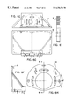
- FIGS. 6A, 6 B, 6 C and 6 D are, respectively, top plan, side elevational, front elevational and bottom plan views of the monitor including the two displays mounted on the cabinet of the imaging system of FIGS. 1-3;
- FIGS. 6E, 6 F and 6 G are, respectively, plan, side elevational and front elevational views of the monitor frame assembly of an exemplary embodiment of the invention, showing the mounting details;
- FIGS. 6H and 6I are, respectively, a plan view of the swivel bearing pad that provides angular rotation capability of 40° in the described embodiment, and a sectional view taken along the line 6 I— 6 I of FIG. 6H;
- FIG. 7 is a block diagram of an example of the deflection PCBs and their interaction with the C-arm system electronics, illustrating an exemplary embodiment of the invention
- FIG. 8 is a block diagram showing the arrangement of views of FIGS. 8A-8F;
- FIGS. 8A-8F collectively, arranged as shown in FIG. 8, constitute a schematic of an example of the 118 DMX Deflection Board providing horizontal and vertical drivers;
- FIG. 9 is a block diagram showing the arrangement of views of FIGS. 9A-9B;
- FIGS. 9A and 9B collectively, arranged as shown in FIG. 9, constitute a schematic of an example of the Vertical Deflection Board
- FIG. 10 is a block diagram showing the arrangement of views of FIGS. 10A-10D;
- FIGS. 10A-10D collectively, arranged as shown in FIG. 10, constitute an overall cable diagram of an example of the entire monitor illustrating detailed interconnections
- FIG. 11 is a simplified and partly schematic side elevational view of a mini C-arm x-ray fluoroscopic imaging system arranged for use to measure forearm BMD of a human patient, in which an embodiment of the present invention may be incorporated.
- FIGS. 1-5 An exemplary x-ray fluoroscopic imaging system incorporating one embodiment of the present application is shown in FIGS. 1-5.
- the imaging system 10 is entirely contained in a wheeled cart or portable cabinet 11 that can easily be rolled from place to place.
- the cabinet includes a generally rectangular, upright body 12 that supports a monitor 14 constituted of two video displays 14 a and 14 b on its top surface and an articulated arm assembly 18 secured thereto.
- the cabinet also contains a computer for processing data. It will be understood that images taken by the imaging system can be shown on only a single display, or printed on a printer which is preferably enclosed within the cabinet.
- the articulating arm assembly 18 includes two arms 18 a and 18 b .
- the distal end of arm 18 b is connected to a support arm assembly 20 that has a C-arm locking mechanism 22 .
- a C-arm 24 of mini C-arm assembly 26 is carried by the support arm assembly 20 such that a track 28 of the C-arm is slidable within the C-arm locking mechanism 22 .
- the mini C-arm assembly 26 also includes an x-ray source assembly 30 and an x-ray detector assembly 34 respectively mounted at opposite extremities of the C-arm in facing relation to each other so that an x-ray beam 36 from an x-ray source 32 within the source assembly impinges on the input end 38 of the detector assembly 34 .
- the x-ray source 32 and detector end 38 are spaced apart by the C-arm sufficiently to define a gap 40 between them, in which the limb or extremity of a human patient 42 can be inserted in the path of the x-ray beam 36 .
- the support arm assembly 20 connected to the end of arm 18 b provides 3-way pivotal mounting that enables the C-arm 24 to be swivelled or rotated through 360° in each of three mutually perpendicular (x, y, z) planes and to be held stably at any desired position, while the arm 18 a of the articulating arm assembly 18 is mounted to the portable cabinet 11 at point “A” and jointed to enable its distal end and the C-arm to be angularly displaced both horizontally and vertically.
- the multidirectional angular movability of the C-arm assembly facilitates the positioning of the x-ray source and detector assemblies in relation to a patient body portion to be irradiated.
- a suitable power supply (not shown) for the x-ray source, and instrumentalities (also not shown) for controlling or varying current (mA) and voltage (kV) , are incorporated in the system as well.
- the C-arm 24 is movable within the C-arm locking mechanism 22 .
- the C-arm locking mechanism is used.
- the C-arm locking mechanism may be a clamp assembly (not shown) which is compressed against the C-arm when tightened, but preferably the C-arm locking mechanism is of the type described in pending U.S. Provisional Patent Application No. 60/066,966 filed on Nov. 28, 1997, which is incorporated herein in its entirety by this reference.
- either the x-ray source assembly or the x-ray detector assembly includes a control panel 50 that is mounted thereon (i.e. at one or the other of the opposed extremities of the C-arm) and is coupled to the imaging system computer to provide a physician with easy access within the sterile field to predefined imaging control functions associated with the x-ray fluoroscopic imaging system.
- a physician can activate certain (or all) functions of the x-ray fluoroscopic imaging system from within the sterile field and without placing a hand or arm within the path of the x-ray beam.
- One result of this configuration is that it gives a physician immediate control of the operating characteristics of the fluoroscope in the event that a regular operator is unavailable or unable to operate controls located outside of the sterile field.
- the control panel has an array of switches, one of which controls the x-ray source to generate a single image or for continuous imaging.
- a physician may depress the x-ray control switch twice in rapid succession and then release the switch so that the x-ray source (or tube) is activated for a single image or strobe shot.
- a physician depresses the x-ray control switch twice in rapid succession and then continues to depress (or hold down) the switch so that the x-ray source is activated and continues to produce x-rays for as long as the switch is depressed to create a real time continuous or cinematic fluoroscopic picture.
- the system 10 is essentially identical to currently available mini C-arm x-ray fluoroscopic imaging systems.
- the system 10 may be a “FluoroScan IV” system, produced by FluoroScan Imaging Systems, Inc., having the following specifications:
- PIXEL ARRAY 768 pixels by 600 lines
- the two video displays 14 a and 14 b are SVGA multiscan CRTs.
- these two displays are mounted vertically together in a single rotatable enclosure 54 (a rigid molded plastic structure with a rotatable mounting) to display the images required by the fluoroscopic imaging system. That is to say, the enclosure 54 encases two high-resolution monochrome displays, monitor controls 57 being located as indicated in FIG. 6 C.
- These are two 15-inch displays with individual yokes, video processor PCBs, and common driver board and low voltage power supplies. They can be displays with IR sensor window 55 for IR sensor control.
- Each of the two displays in FIG. 6 has the following pertinent specifications:
- FIGS. 6E, 6 F and 6 G illustrate the monitor frame assembly 56 showing the mounting details.
- the frame is spot welded or arc welded as required to produce a rigid assembly of dual displays.
- Each display is mounted in the vertical position, as opposed to the horizontal position of a display. This provides the surgeon with the best display possible from all angles.
- FIGS. 6H and 6I illustrates the swivel bearing pad 58 that provides 40° adjustability (rotatability about a vertical axis) of the system for ease of viewing.
- the described embodiment of the invention provides a monitor assembly that is modular, has high resolution 15-inch twin displays, and is easily adjustable for the surgeon's viewing of the x-ray output.
- the monitor uses a single driver interface (FIG. 7) for 100% synchronous operation of both displays to display the images required by the fluoroscopic imaging system.
- the actual circuitry resides on two PCBs.
- FIG. 7 is a block diagram of an illustrative example of the two single driver interface PCBs (deflection PCBs) respectively designated 156 and 158 and their interaction with the C-arm system electronics.
- the monitor system incorporates a single power interface, dual SVGA display video interfaces, IR remote interface and x-ray on indicator interface, and, as a particular feature of the present invention, a single driver interface. This driver interface ensures 100% synchronous operation of both displays.
- FIG. 8 in its various parts, is a schematic of the 118 DMX Deflection Board 156 .
- This board utilizes a single horizontal sync input and generates horizontal drives for both horizontal deflection yokes. It provides power for the picture tube filaments and creates a dynamic focus for both tubes.
- This board also provides the vertical deflection for one of the picture tubes and sync for the other picture tube. The vertical drive portion of this board's circuitry is replicated on the other deflection board.
- the bill of materials for this board is as follows:
- This board is used to provide the vertical drive for the second monitor. It is synced to the main deflector board through connector H401 receiving vertical sync as an input. The board provides controls for vertical hold, vertical linearity, and vertical centering for proper vertical adjustment. Its output is a vertical drive signal that has been processed through IC400 driving the yoke.
- the schematic for this board is shown in the various parts of FIG. 9 . Its bill of materials is as follows:
- An overall cable diagram is shown in the various parts of FIG. 10 . It provides details of the wiring between the deflection boards, the yokes, the CRTs, and the overall monitor wiring interconnections.
- the described embodiment of the invention provides a monitor assembly that is modular, has high resolution 15-inch twin displays, and is easily adjustable for the surgeon's viewing of the x-ray output.
- the image intensifier employed in the detector may be either of a type that intensifies optical images (as in the above-described “FluoroScan IV” system) or of a type that intensifies x-ray images.
- the detector may be a direct digital 2-dimensional x-ray detector; an example of such a device is the “FlashScan 20” high resolution flat panel device of dpiX, A Xerox Company, which is an amorphous silicon image sensor that acquires conventional x-ray images and converts them to digital form in a way that can provide fluoroscopic imaging in real time.
- FIG. 13 Such an alternative embodiment of the x-ray fluoroscopic imaging system which can be used to measure bone mineral density (BMD) in, for example, the forearm, wrist, ankle or heel of a human patient will be described with reference to FIG. 13 .
- This imaging system 200 is also entirely contained in a wheeled cart or cabinet 210 that can easily be rolled from place to place.
- the cabinet includes a generally rectangular, upright body 212 that supports a monitor 214 having two displays (only one being shown) on its top surface and has, in its upper portion, a keyboard 216 and an articulated member 218 ; the cabinet also contains a computer (not shown) for processing data as hereinafter further discussed.
- the two displays, with their mounting and circuitry, may incorporate features of the present invention.
- articulated member 218 carries a mini C-arm 220 having an x-ray source 222 and a detector 224 respectively fixedly mounted at its opposite extremities so that an x-ray beam 226 from source 222 impinges on the input end 228 of the detector, the source and detector being spaced apart by the C-arm sufficiently to define a gap 229 between them, in which the limb or extremity of a human patient 230 can be inserted in the path of the x-ray beam 226 .
- the C-arm is connected to the end of member 218 by a 3-way pivotal mounting 232 that enables the C-arm to be swivelled or rotated through 360° in each of three mutually perpendicular (x, y, z) planes and to be held stably at any desired position, while the member 218 is itself mounted and jointed to enable its outer end and the C-arm to be angularly displaced both horizontally and vertically.
- the multidirectional angular movability of the mini C-arm facilitates the positioning of the source and detector in relation to a patient body portion to be irradiated.
- either the x-ray source or the x-ray detector includes a control panel 250 that is coupled to the imaging system computer to provide a physician with easy access within the sterile field to predefined imaging control functions associated with the x-ray fluoroscopic imaging system.
- the control panel 250 is illustrated in FIG. 13 as being mounted on the detector 224 .
- the control panel 250 like the panel 50 of FIG. 8, includes an array of membrane switches, each of which is provided to activate at least one function performed by the x-ray fluoroscopic imaging system.
- each switch in the array has a raised button profile which provides tactile feedback, completes a signal circuit when contact material mounted on the underside of the raised button profile which provides tactile feedback is depressed to a base layer and breaks the signal circuit when pressure on the contact material is released.
- the beam 226 emitted by the x-ray source 222 is a cone-shaped beam (i.e. a volume beam as opposed to a pencil beam or fan beam) that impinges on a flat x-ray-sensitive receiving surface of the detector 224 at or adjacent the detector input end; this receiving surface faces the source across the gap 229 and is perpendicular to the axis of the beam path, so that the intersection of the receiving surface and the conical x-ray beam is an extended circular (2-dimensional) area.
- the term “field of view” is used herein to refer to the latter circular area, or that portion of it to which the detector responds, and also to designate the region, within the beam path or gap 229 , the contents of which will be imaged by the detector. It will be understood that the area of the field of view as measured in a plane transverse to the beam path axis is sufficient to encompass objects of the size desired to be imaged or otherwise studied, e.g. a human wrist or heel.
- the receiving surface of the detector 224 is a surface of an x-ray-to-visible-light converter, such as a layer of phosphor or scintillator material covered externally by a light shield, that converts impinging x-rays to visible light.
- the detector may include a Cesium Iodide vacuum tube image intensifier or an image intensifier of the high-gain microchannel plate type, and a planar output surface on which is produced an output visible-light image of the field of view, in accordance with well-known principles of fluoroscopic imaging.
- the combined converter and image intensifier elements of the detector 224 may be as described in the aforementioned U.S. Pat. No. 4,142,101 which is incorporated herein by reference.
- the detector assembly includes a video camera (not separately shown) for viewing the image on the aforementioned planar output surface and producing a signal output representative of that viewed image.
- the video camera can be a television camera and can operate according to a video standard such as NTSC or CCIR.
- the signal output of the video camera is processed by the onboard computer to produce video images on one or both monitors 214 ; the system also includes devices for recording and, optionally, printing out these video fluoroscopic images.
- the system 200 is essentially identical to currently available mini C-arm x-ray fluoroscopic imaging systems, e.g. having specifications as set forth above for the system 10 of FIG. 1 .
- a power supply for the x-ray source, and instrumentalities for controlling or varying current (mA) and voltage (kV), not shown, are incorporated in the system as well.
- the detector in the fluoroscopic imaging system detects x-ray emission from a cone-beam source over an extended two-dimensional area (the cross-section of the x-ray beam path in the plane of the detector receiving surface), there is inherent variation (i.e., variation attributable to the source and/or the detector having the image intensifier, independent of attenuation by any object interposed in the beam path) in received radiation intensity over the field of view.
- the image data obtained for the wrist and calibration bone sample by the steps described above are corrected for this inherent variation in order to enable more accurate calculation of BMD.
- the calculation of data to produce BMD measurements could be performed with an onboard computer in a mini C-arm fluoroscopic system such as the “FluoroScan III” system, or in another computer.
- the functions of data acquisition/storage and BMD computation therefrom could be performed by different computers.
- the logarithmic conversion could be performed first (e.g. with a log amplifier) and digitized thereafter.
- appropriate software could be employed to re-register the images if there is movement.
Abstract
Description
| 118 DMX DEFLFECTION BOARD BILL OF MATERIAL |
| ITEM NUMBER | DESCRIPTION | ||
| R100 | 1K, 1W | ||
| R200 | 1K | ||
| R201 | 1K | ||
| R202 | 1K | ||
| R203 | 270 | ||
| R204 | 100 | ||
| R207 | 1K | ||
| R208 | 470 | ||
| R209 | 4.7K | ||
| R210 | 4.7K | ||
| R300 | 1K, 1W | ||
| R301 | 10K | ||
| R302 | 27K | ||
| R304A | 100 | ||
| R304B | 0 | ||
| R305A | 150 OHM, 2W | ||
| R305B | 150 OHM, 2W | ||
| R306 | 220 | ||
| R307 | 1.2K | ||
| R308 | 100K | ||
| R309 | 47K | ||
| R310 | 680 | ||
| R311 | .47, 1W | ||
| R312 | 1K, 1W | ||
| R400 | 20, 5W | ||
| R401 | 10K | ||
| R402 | 15K | ||
| R403 | 4.7K | ||
| R406 | 47K | ||
| R408 | 1K | ||
| R409 | 47 | ||
| R410 | 2.2K | ||
| R411 | 220 | ||
| R412 | .82, 1W | ||
| R415 | 18 | ||
| R417 | 270, 1W | ||
| R418 | 150, 1W | ||
| R419 | 2.2K | ||
| R420 | 4.7K | ||
| R421 | 180K | ||
| R422 | 6.8K | ||
| VR300 | 500 | ||
| VR400 | 5K | ||
| VR401 | 250K | ||
| VR402 | 100K | ||
| VR403 | 20K | ||
| C100 | 100 UF, 50V | ||
| C200 | 10 UF | ||
| C201 | 10 UF | ||
| C202 | .1 UF | ||
| C203 | .1 UF | ||
| C300 | 47 UF, 16V | ||
| C301 | 5600 PF | ||
| C302 | 4.7 UF, 50V | ||
| C303 | .0047 UF | ||
| C304 | .01 UF, 250V | ||
| C305 | 330 UF, 35V | ||
| C306 | 100 PF | ||
| C307 | .0047 UF | ||
| C310 | 390 PF | ||
| C311 | 1 UF | ||
| C313 | 100 UF, 50V | ||
| C314 | 0.012 UF | ||
| C315 | 0.012 UF | ||
| C316 | 0.012 UF | ||
| C317 | 0.012 UF | ||
| C318 | 150 UF, 160V | ||
| C319 | 47 UF, 50V | ||
| C400 | 1000 UF, 35V | ||
| C401 | .1 UF | ||
| C402 | 330 UF, 35V | ||
| C403 | 0.0047 PF | ||
| C405 | .1 UF | ||
| C406 | .1 UF | ||
| C407 | .1 UF | ||
| C408 | .15 UF | ||
| C409 | 47 UF, 16V | ||
| C410 | 1000 UF, 35V | ||
| C411 | 0.01 UF | ||
| C502 | 100 UF, 50V | ||
| C601 | .68 UF, 200V | ||
| C602 | .01 UF, 1KV | ||
| C603 | .01 UF | ||
| D100 | 1N5231 | ||
| D300 | 86-107-14 | ||
| D301 | 1N4740 | ||
| D302 | MUR8100E | ||
| D400 | 1N4007 | ||
| D402 | 1N4148 | ||
| D403 | FR157 | ||
| D502 | FR157 | ||
| Q300 | 2N6715 | ||
| Q301B | MJ116206 | ||
| Q401 | 2N4402 | ||
| Q402 | 2N4401 | ||
| IC200A | 74LS86 | ||
| IC300 | AN5435 | ||
| IC400 | TDA1675A | ||
| T300 | DRIVE TRANSFORMER | ||
| T301 | HORIZONTAL DEFLECTION YOKE | ||
| T600 | FOCUS | ||
| VERTICAL DEFLECTION BOARD BILL OF MATERIAL |
| ITEM | DESCRIPTION | ||
| R400 | |||
| 20 OHM, | |||
| |
10K | ||
| R402 | |||
| 15K | |||
| R403 | 4.7K | ||
| | 560K | ||
| R406 | |||
| 47K | |||
| R407 | 2.2 | ||
| R408 | 1K | ||
| R409 | 47 | ||
| R410 | 2.2K | ||
| |
220 | ||
| R412 | .82 OHM, 1W, | ||
| R415 | |||
| 18 | |||
| R417 | 270 | ||
| |
150 | ||
| |
1K | ||
| R420 | 2.2 | ||
| R421 | |||
| 10K | |||
| R422 | 6.8K | ||
| | 180K | ||
| |
5K | ||
| |
250K | ||
| |
100K | ||
| |
10K | ||
| C400 | |||
| 1000 UF, 35V | |||
| C401 | .1 | ||
| C402 | |||
| 220 UF, 35V | |||
| C404 | .33 UF, 35V | ||
| C405 | .1 UF | ||
| C406 | .1 UF | ||
| C407 | .1 UF | ||
| C408 | .15 | ||
| C409 | |||
| 47 UF, | |||
| C410 | |||
| 1000 UF, 35V | |||
| C411 | 0.01 | ||
| C415 | |||
| 1000 UF, 35V | |||
| C416 | .1 UF | ||
| D400 | 1N4007 | ||
| D402 | 1N4148 | ||
| Q401 | 2N4402 | ||
| Q402 | 2N4402 | ||
| IC400 | TDA 1675 | ||
Claims (6)
Priority Applications (1)
| Application Number | Priority Date | Filing Date | Title |
|---|---|---|---|
| US09/419,593 US6256374B1 (en) | 1998-10-19 | 1999-10-18 | Miniature C-arm apparatus with dual video display monitor and single driver interface therefor |
Applications Claiming Priority (3)
| Application Number | Priority Date | Filing Date | Title |
|---|---|---|---|
| US10481098P | 1998-10-19 | 1998-10-19 | |
| US10996898P | 1998-11-25 | 1998-11-25 | |
| US09/419,593 US6256374B1 (en) | 1998-10-19 | 1999-10-18 | Miniature C-arm apparatus with dual video display monitor and single driver interface therefor |
Publications (1)
| Publication Number | Publication Date |
|---|---|
| US6256374B1 true US6256374B1 (en) | 2001-07-03 |
Family
ID=26801973
Family Applications (1)
| Application Number | Title | Priority Date | Filing Date |
|---|---|---|---|
| US09/419,593 Expired - Lifetime US6256374B1 (en) | 1998-10-19 | 1999-10-18 | Miniature C-arm apparatus with dual video display monitor and single driver interface therefor |
Country Status (6)
| Country | Link |
|---|---|
| US (1) | US6256374B1 (en) |
| EP (1) | EP1123640A4 (en) |
| JP (1) | JP2002528150A (en) |
| AU (1) | AU1210100A (en) |
| CA (1) | CA2347782A1 (en) |
| WO (1) | WO2000024234A1 (en) |
Cited By (25)
| Publication number | Priority date | Publication date | Assignee | Title |
|---|---|---|---|---|
| US20030142788A1 (en) * | 2001-11-21 | 2003-07-31 | Kenneth Cho | Portable medical digital radiography assembly |
| KR20040016195A (en) * | 2002-08-16 | 2004-02-21 | 케이엔디티앤아이 주식회사 | Radiograph viewer having a double viewing window |
| US20050047554A1 (en) * | 2003-08-25 | 2005-03-03 | Borom Andrew H. | Attachable surgical table |
| US20050052527A1 (en) * | 2003-08-20 | 2005-03-10 | Christophe Remy | Mobile videoimaging, videocommunication, video production (VCVP) system |
| US7108422B2 (en) | 2003-08-25 | 2006-09-19 | Borom Andrew H | Integrated surgical table drape |
| US20070129182A1 (en) * | 2005-12-05 | 2007-06-07 | Taylor Bradford C | Assembly for training hand/eye coordination |
| US20080139917A1 (en) * | 2006-12-12 | 2008-06-12 | Kevin Herman | Monitor Assembly for Diagnostic Device |
| US20090240137A1 (en) * | 2008-03-23 | 2009-09-24 | Scott Rosa | Diagnostic Imaging Method |
| US20100002844A1 (en) * | 2005-10-19 | 2010-01-07 | Koninklijke Philips Electronics N.V. | X-ray examination apparatus |
| USRE42091E1 (en) | 1998-11-20 | 2011-02-01 | Jerry Moscovitch | Computer display screen system and adjustable screen mount, and swinging screens therefor |
| US8102331B1 (en) * | 1999-11-12 | 2012-01-24 | Jerry Moscovitch | Horizontal three screen LCD display system |
| US20120093298A1 (en) * | 2010-04-13 | 2012-04-19 | Lalena Michael C | Mobile radiography unit having multiple monitors |
| US20140233703A1 (en) * | 2013-02-15 | 2014-08-21 | Canon Kabushiki Kaisha | Movable x-ray generation apparatus |
| US8899834B2 (en) | 2012-04-18 | 2014-12-02 | General Electric Company | Pivot joint brakes for X-ray positioning system |
| US20150216493A1 (en) * | 2012-12-03 | 2015-08-06 | Nanofocusray Co., Ltd. | Portable x-ray image system and operating table using the same |
| US9125611B2 (en) | 2010-12-13 | 2015-09-08 | Orthoscan, Inc. | Mobile fluoroscopic imaging system |
| US20160045177A1 (en) * | 2013-03-27 | 2016-02-18 | Siemens Aktiengesellschaft | X-ray device |
| US9398675B2 (en) | 2009-03-20 | 2016-07-19 | Orthoscan, Inc. | Mobile imaging apparatus |
| US9693437B2 (en) | 2012-04-13 | 2017-06-27 | General Electric Company | Systems and methods for controlling X-ray imaging systems |
| WO2018060511A3 (en) * | 2016-09-30 | 2018-05-17 | Koninklijke Philips N.V. | Docking viewing system for mobile x-ray systems |
| USD836779S1 (en) | 2017-04-17 | 2018-12-25 | General Electric Company | Compact mobile C arm system |
| US20190246998A1 (en) * | 2018-02-12 | 2019-08-15 | General Electric Company | C-arm imaging system having coaxial independent rotation of monitors |
| US10485499B2 (en) | 2017-04-17 | 2019-11-26 | General Electric Company | Method and systems for a compact integrated monitor arm for an imaging system |
| EP2785150B1 (en) * | 2004-02-20 | 2020-04-08 | Aribex, Inc. | Handheld x-ray device |
| US11375962B2 (en) * | 2019-08-05 | 2022-07-05 | Linev Systems, Inc. | Fast foreign object scanner for scanning human bodies |
Families Citing this family (6)
| Publication number | Priority date | Publication date | Assignee | Title |
|---|---|---|---|---|
| WO2004004568A1 (en) * | 2002-07-02 | 2004-01-15 | Hitachi Medical Corporation | Moving x-ray inspection apparatus |
| JP4133041B2 (en) * | 2002-07-02 | 2008-08-13 | 株式会社日立メディコ | Mobile X-ray device |
| US7319738B2 (en) * | 2004-10-08 | 2008-01-15 | General Electric Company | Delivering X-ray systems to pipe installations |
| DE102006032094A1 (en) * | 2006-07-11 | 2008-01-17 | Siemens Ag | X-ray system with an industrial robot |
| JP4179564B2 (en) | 2006-12-05 | 2008-11-12 | 株式会社日立メディコ | X-ray fluoroscopy table and X-ray fluoroscopy system |
| AU2010284153B2 (en) * | 2009-08-21 | 2015-05-28 | Ecolab Usa Inc. | Universal C arm tape drape |
Citations (7)
| Publication number | Priority date | Publication date | Assignee | Title |
|---|---|---|---|---|
| US4142101A (en) | 1977-07-20 | 1979-02-27 | The United States Of America As Represented By The Administrator Of The National Aeronautics And Space Administration | Low intensity X-ray and gamma-ray imaging device |
| US4674107A (en) * | 1985-07-31 | 1987-06-16 | Picker International, Inc. | Display for radiation imaging |
| US5379334A (en) * | 1992-07-20 | 1995-01-03 | Heimann Systems Gmbh & Co. Kg | Object testing system |
| US5627873A (en) * | 1995-08-04 | 1997-05-06 | Oec Medical Systems, Inc. | Mini C-arm assembly for mobile X-ray imaging system |
| US5949846A (en) | 1997-02-03 | 1999-09-07 | Hologic, Inc. | Bone densitometry using x-ray imaging systems |
| US6007243A (en) | 1996-02-21 | 1999-12-28 | Lunar Corporation | Combined mobile x-ray imaging system and monitor cart |
| US6113265A (en) | 1997-11-28 | 2000-09-05 | Fluorscan Imaging Systems, Inc. | C-arm apparatus with improved C-arm locking mechanism |
Family Cites Families (5)
| Publication number | Priority date | Publication date | Assignee | Title |
|---|---|---|---|---|
| US5065761A (en) * | 1989-07-12 | 1991-11-19 | Diasonics, Inc. | Lithotripsy system |
| US5091926A (en) * | 1990-03-26 | 1992-02-25 | Horton Jerry L | Head activated fluoroscopic control |
| US5387941A (en) * | 1991-06-14 | 1995-02-07 | Wavephore, Inc. | Data with video transmitter |
| US5748696A (en) * | 1993-11-26 | 1998-05-05 | Kabushiki Kaisha Toshiba | Radiation computed tomography apparatus |
| US5586162A (en) * | 1994-06-20 | 1996-12-17 | Micro Focus Imaging Corp. | Portable X-ray machine |
-
1999
- 1999-10-18 EP EP99970835A patent/EP1123640A4/en not_active Withdrawn
- 1999-10-18 WO PCT/US1999/024302 patent/WO2000024234A1/en not_active Application Discontinuation
- 1999-10-18 JP JP2000577866A patent/JP2002528150A/en active Pending
- 1999-10-18 US US09/419,593 patent/US6256374B1/en not_active Expired - Lifetime
- 1999-10-18 CA CA002347782A patent/CA2347782A1/en not_active Abandoned
- 1999-10-18 AU AU12101/00A patent/AU1210100A/en not_active Abandoned
Patent Citations (9)
| Publication number | Priority date | Publication date | Assignee | Title |
|---|---|---|---|---|
| US4142101A (en) | 1977-07-20 | 1979-02-27 | The United States Of America As Represented By The Administrator Of The National Aeronautics And Space Administration | Low intensity X-ray and gamma-ray imaging device |
| US4142101B1 (en) | 1977-07-20 | 1991-02-19 | Low intensity x-ray and gamma-ray imaging device | |
| US4674107A (en) * | 1985-07-31 | 1987-06-16 | Picker International, Inc. | Display for radiation imaging |
| US5379334A (en) * | 1992-07-20 | 1995-01-03 | Heimann Systems Gmbh & Co. Kg | Object testing system |
| US5627873A (en) * | 1995-08-04 | 1997-05-06 | Oec Medical Systems, Inc. | Mini C-arm assembly for mobile X-ray imaging system |
| US5627873B1 (en) * | 1995-08-04 | 2000-03-14 | Oec Medical Systems | Mini c-arm assembly for mobile x-ray imaging system |
| US6007243A (en) | 1996-02-21 | 1999-12-28 | Lunar Corporation | Combined mobile x-ray imaging system and monitor cart |
| US5949846A (en) | 1997-02-03 | 1999-09-07 | Hologic, Inc. | Bone densitometry using x-ray imaging systems |
| US6113265A (en) | 1997-11-28 | 2000-09-05 | Fluorscan Imaging Systems, Inc. | C-arm apparatus with improved C-arm locking mechanism |
Non-Patent Citations (1)
| Title |
|---|
| U.S. Patent application No. 09/270,373 filed Mar. 16, 1999, Tomasetti et al. |
Cited By (43)
| Publication number | Priority date | Publication date | Assignee | Title |
|---|---|---|---|---|
| USRE42091E1 (en) | 1998-11-20 | 2011-02-01 | Jerry Moscovitch | Computer display screen system and adjustable screen mount, and swinging screens therefor |
| US8102331B1 (en) * | 1999-11-12 | 2012-01-24 | Jerry Moscovitch | Horizontal three screen LCD display system |
| US6754306B2 (en) * | 2001-11-21 | 2004-06-22 | The United States Of America As Represented By The Secretary Of The Army | Portable medical digital radiography assembly |
| US20030142788A1 (en) * | 2001-11-21 | 2003-07-31 | Kenneth Cho | Portable medical digital radiography assembly |
| KR20040016195A (en) * | 2002-08-16 | 2004-02-21 | 케이엔디티앤아이 주식회사 | Radiograph viewer having a double viewing window |
| US20050052527A1 (en) * | 2003-08-20 | 2005-03-10 | Christophe Remy | Mobile videoimaging, videocommunication, video production (VCVP) system |
| US7432949B2 (en) * | 2003-08-20 | 2008-10-07 | Christophe Remy | Mobile videoimaging, videocommunication, video production (VCVP) system |
| US20050047554A1 (en) * | 2003-08-25 | 2005-03-03 | Borom Andrew H. | Attachable surgical table |
| US6984066B2 (en) | 2003-08-25 | 2006-01-10 | Borom Andrew H | Attachable surgical table |
| US7108422B2 (en) | 2003-08-25 | 2006-09-19 | Borom Andrew H | Integrated surgical table drape |
| EP2785150B1 (en) * | 2004-02-20 | 2020-04-08 | Aribex, Inc. | Handheld x-ray device |
| US20100002844A1 (en) * | 2005-10-19 | 2010-01-07 | Koninklijke Philips Electronics N.V. | X-ray examination apparatus |
| US8000446B2 (en) * | 2005-10-19 | 2011-08-16 | Koninklijke Philips Electronics N.V. | X-ray examination apparatus |
| US7300365B2 (en) * | 2005-12-05 | 2007-11-27 | Bradford Carter Taylor | Assembly for training hand/eye coordination |
| US20070129182A1 (en) * | 2005-12-05 | 2007-06-07 | Taylor Bradford C | Assembly for training hand/eye coordination |
| US20080139917A1 (en) * | 2006-12-12 | 2008-06-12 | Kevin Herman | Monitor Assembly for Diagnostic Device |
| US7821778B2 (en) * | 2006-12-12 | 2010-10-26 | Kevin Herman | Monitor assembly for diagnostic device |
| US9730631B1 (en) | 2008-03-23 | 2017-08-15 | Scott L Rosa | Diagnostic imaging method |
| US8571633B2 (en) | 2008-03-23 | 2013-10-29 | Scott Rosa | Diagnostic imaging method |
| US20090240137A1 (en) * | 2008-03-23 | 2009-09-24 | Scott Rosa | Diagnostic Imaging Method |
| US9398675B2 (en) | 2009-03-20 | 2016-07-19 | Orthoscan, Inc. | Mobile imaging apparatus |
| US20120093298A1 (en) * | 2010-04-13 | 2012-04-19 | Lalena Michael C | Mobile radiography unit having multiple monitors |
| US8961011B2 (en) * | 2010-04-13 | 2015-02-24 | Carestream Health, Inc. | Mobile radiography unit having multiple monitors |
| US9125611B2 (en) | 2010-12-13 | 2015-09-08 | Orthoscan, Inc. | Mobile fluoroscopic imaging system |
| US10178978B2 (en) | 2010-12-13 | 2019-01-15 | Orthoscan, Inc. | Mobile fluoroscopic imaging system |
| US9833206B2 (en) | 2010-12-13 | 2017-12-05 | Orthoscan, Inc. | Mobile fluoroscopic imaging system |
| US9693437B2 (en) | 2012-04-13 | 2017-06-27 | General Electric Company | Systems and methods for controlling X-ray imaging systems |
| US9025730B2 (en) | 2012-04-18 | 2015-05-05 | General Electric Company | Electrically controlled brakes for arm joints on a mini C-arm mobile X-ray system |
| US8899834B2 (en) | 2012-04-18 | 2014-12-02 | General Electric Company | Pivot joint brakes for X-ray positioning system |
| US9364189B2 (en) * | 2012-12-03 | 2016-06-14 | Nanofocusray Co., Ltd. | Portable x-ray image system and operating table using the same |
| US20150216493A1 (en) * | 2012-12-03 | 2015-08-06 | Nanofocusray Co., Ltd. | Portable x-ray image system and operating table using the same |
| US20140233703A1 (en) * | 2013-02-15 | 2014-08-21 | Canon Kabushiki Kaisha | Movable x-ray generation apparatus |
| US9295438B2 (en) * | 2013-02-15 | 2016-03-29 | Canon Kabushiki Kaisha | Movable X-ray generation apparatus |
| US9782139B2 (en) * | 2013-03-27 | 2017-10-10 | Siemens Aktiengesellschaft | X-ray device |
| US20160045177A1 (en) * | 2013-03-27 | 2016-02-18 | Siemens Aktiengesellschaft | X-ray device |
| WO2018060511A3 (en) * | 2016-09-30 | 2018-05-17 | Koninklijke Philips N.V. | Docking viewing system for mobile x-ray systems |
| CN109788930A (en) * | 2016-09-30 | 2019-05-21 | 皇家飞利浦有限公司 | For moving the docking observing system of x-ray system |
| US11197648B2 (en) | 2016-09-30 | 2021-12-14 | Koninklijke Philips N.V. | Docking viewing system for mobile X-ray systems |
| USD836779S1 (en) | 2017-04-17 | 2018-12-25 | General Electric Company | Compact mobile C arm system |
| US10485499B2 (en) | 2017-04-17 | 2019-11-26 | General Electric Company | Method and systems for a compact integrated monitor arm for an imaging system |
| US10799201B2 (en) * | 2018-02-12 | 2020-10-13 | General Electric Company | C-arm imaging system having coaxial independent rotation of monitors |
| US20190246998A1 (en) * | 2018-02-12 | 2019-08-15 | General Electric Company | C-arm imaging system having coaxial independent rotation of monitors |
| US11375962B2 (en) * | 2019-08-05 | 2022-07-05 | Linev Systems, Inc. | Fast foreign object scanner for scanning human bodies |
Also Published As
| Publication number | Publication date |
|---|---|
| AU1210100A (en) | 2000-05-08 |
| EP1123640A1 (en) | 2001-08-16 |
| EP1123640A4 (en) | 2004-05-06 |
| JP2002528150A (en) | 2002-09-03 |
| CA2347782A1 (en) | 2000-04-27 |
| WO2000024234A1 (en) | 2000-04-27 |
Similar Documents
| Publication | Publication Date | Title |
|---|---|---|
| US6256374B1 (en) | Miniature C-arm apparatus with dual video display monitor and single driver interface therefor | |
| US6234672B1 (en) | Miniature C-arm apparatus with C-arm mounted controls | |
| US6236712B1 (en) | Miniature C-arm apparatus with multiple x-ray indicators | |
| US11311258B2 (en) | Independently rotatable detector plate for medical imaging device | |
| US5949846A (en) | Bone densitometry using x-ray imaging systems | |
| EP1004271B1 (en) | Support system for use in radiographic imaging equipment | |
| US11647976B2 (en) | Imaging systems and methods | |
| US6431751B1 (en) | Ceiling mounted, transportable, surgical C-arm with flat panel image receptor | |
| US5912943A (en) | Cooling system for a sealed housing positioned in a sterile environment | |
| US6031888A (en) | Fluoro-assist feature for a diagnostic imaging device | |
| US5038371A (en) | X-ray examination apparatus having three axes of rotation | |
| US20020085681A1 (en) | Method and apparatus for obtaining and displaying computed tomography images using a fluoroscopy imaging system | |
| JPH11226002A (en) | Image forming system | |
| US20140037058A1 (en) | C-Arm with Removable or Retractable Detector Housing | |
| JP4508326B2 (en) | X-ray fluoroscopic equipment | |
| US6075837A (en) | Image minifying radiographic and fluoroscopic x-ray system | |
| US7194065B1 (en) | Method and apparatus for control of exposure in radiological imaging systems | |
| WO2000019781A2 (en) | Miniature c-arm apparatus with c-arm mounted compact oil immersion power supply | |
| US4937848A (en) | X-ray examination apparatus with referencing system for the video display | |
| JP2010063586A (en) | Method of changing display direction of image, and x-ray apparatus using the same | |
| EP0506172A2 (en) | X-ray examination apparatus and console system suitable for use in such an X-ray examination apparatus | |
| JPH1147122A (en) | X-ray image diagnostic device | |
| JP2000271115A (en) | Medical x-ray system | |
| CN113543716A (en) | X-ray imaging apparatus | |
| WO2007057764A2 (en) | Auxiliary positioning apparatus for use with linear scanning x-ray system |
Legal Events
| Date | Code | Title | Description |
|---|---|---|---|
| AS | Assignment |
Owner name: FLUOROSCAN IMAGING SYSTEMS, INC., ILLINOIS Free format text: ASSIGNMENT OF ASSIGNORS INTEREST;ASSIGNORS:TOMASETTI, PERRY J.;BROWN, SANDRA L.;REEL/FRAME:010455/0104 Effective date: 19991022 Owner name: FLUOROSCAN IMAGING SYSTEMS, INC., ILLINOIS Free format text: ASSIGNMENT OF ASSIGNORS INTEREST;ASSIGNOR:HIGGINS, WILLIAM E.;REEL/FRAME:010455/0149 Effective date: 19991206 |
|
| STCF | Information on status: patent grant |
Free format text: PATENTED CASE |
|
| FPAY | Fee payment |
Year of fee payment: 4 |
|
| AS | Assignment |
Owner name: GOLDMAN SACHS CREDIT PARTNERS L.P., CALIFORNIA Free format text: PATENT SECURITY AGREEMENT;ASSIGNOR:HOLOGIC, INC.;REEL/FRAME:020018/0818 Effective date: 20071022 Owner name: GOLDMAN SACHS CREDIT PARTNERS L.P.,CALIFORNIA Free format text: PATENT SECURITY AGREEMENT;ASSIGNOR:HOLOGIC, INC.;REEL/FRAME:020018/0818 Effective date: 20071022 |
|
| AS | Assignment |
Owner name: GOLDMAN SACHS CREDIT PARTNERS L.P., AS COLLATERAL Free format text: PATENT SECURITY AGREEMENT;ASSIGNOR:HOLOGIC, INC.;REEL/FRAME:021301/0796 Effective date: 20080717 |
|
| FPAY | Fee payment |
Year of fee payment: 8 |
|
| REMI | Maintenance fee reminder mailed | ||
| AS | Assignment |
Owner name: CYTYC SURGICAL PRODUCTS III, INC., MASSACHUSETTS Free format text: TERMINATION OF PATENT SECURITY AGREEMENTS AND RELEASE OF SECURITY INTERESTS;ASSIGNOR:GOLDMAN SACHS CREDIT PARTNERS, L.P., AS COLLATERAL AGENT;REEL/FRAME:024944/0315 Effective date: 20100819 Owner name: CYTYC SURGICAL PRODUCTS II LIMITED PARTNERSHIP, MA Free format text: TERMINATION OF PATENT SECURITY AGREEMENTS AND RELEASE OF SECURITY INTERESTS;ASSIGNOR:GOLDMAN SACHS CREDIT PARTNERS, L.P., AS COLLATERAL AGENT;REEL/FRAME:024944/0315 Effective date: 20100819 Owner name: CYTYC CORPORATION, MASSACHUSETTS Free format text: TERMINATION OF PATENT SECURITY AGREEMENTS AND RELEASE OF SECURITY INTERESTS;ASSIGNOR:GOLDMAN SACHS CREDIT PARTNERS, L.P., AS COLLATERAL AGENT;REEL/FRAME:024944/0315 Effective date: 20100819 Owner name: SUROS SURGICAL SYSTEMS, INC., INDIANA Free format text: TERMINATION OF PATENT SECURITY AGREEMENTS AND RELEASE OF SECURITY INTERESTS;ASSIGNOR:GOLDMAN SACHS CREDIT PARTNERS, L.P., AS COLLATERAL AGENT;REEL/FRAME:024944/0315 Effective date: 20100819 Owner name: CYTYC SURGICAL PRODUCTS LIMITED PARTNERSHIP, MASSA Free format text: TERMINATION OF PATENT SECURITY AGREEMENTS AND RELEASE OF SECURITY INTERESTS;ASSIGNOR:GOLDMAN SACHS CREDIT PARTNERS, L.P., AS COLLATERAL AGENT;REEL/FRAME:024944/0315 Effective date: 20100819 Owner name: THIRD WAVE TECHNOLOGIES, INC., WISCONSIN Free format text: TERMINATION OF PATENT SECURITY AGREEMENTS AND RELEASE OF SECURITY INTERESTS;ASSIGNOR:GOLDMAN SACHS CREDIT PARTNERS, L.P., AS COLLATERAL AGENT;REEL/FRAME:024944/0315 Effective date: 20100819 Owner name: DIRECT RADIOGRAPHY CORP., DELAWARE Free format text: TERMINATION OF PATENT SECURITY AGREEMENTS AND RELEASE OF SECURITY INTERESTS;ASSIGNOR:GOLDMAN SACHS CREDIT PARTNERS, L.P., AS COLLATERAL AGENT;REEL/FRAME:024944/0315 Effective date: 20100819 Owner name: BIOLUCENT, LLC, CALIFORNIA Free format text: TERMINATION OF PATENT SECURITY AGREEMENTS AND RELEASE OF SECURITY INTERESTS;ASSIGNOR:GOLDMAN SACHS CREDIT PARTNERS, L.P., AS COLLATERAL AGENT;REEL/FRAME:024944/0315 Effective date: 20100819 Owner name: CYTYC PRENATAL PRODUCTS CORP., MASSACHUSETTS Free format text: TERMINATION OF PATENT SECURITY AGREEMENTS AND RELEASE OF SECURITY INTERESTS;ASSIGNOR:GOLDMAN SACHS CREDIT PARTNERS, L.P., AS COLLATERAL AGENT;REEL/FRAME:024944/0315 Effective date: 20100819 Owner name: R2 TECHNOLOGY, INC., CALIFORNIA Free format text: TERMINATION OF PATENT SECURITY AGREEMENTS AND RELEASE OF SECURITY INTERESTS;ASSIGNOR:GOLDMAN SACHS CREDIT PARTNERS, L.P., AS COLLATERAL AGENT;REEL/FRAME:024944/0315 Effective date: 20100819 Owner name: HOLOGIC, INC., MASSACHUSETTS Free format text: TERMINATION OF PATENT SECURITY AGREEMENTS AND RELEASE OF SECURITY INTERESTS;ASSIGNOR:GOLDMAN SACHS CREDIT PARTNERS, L.P., AS COLLATERAL AGENT;REEL/FRAME:024944/0315 Effective date: 20100819 |
|
| AS | Assignment |
Owner name: GOLDMAN SACHS BANK USA, NEW YORK Free format text: SECURITY AGREEMENT;ASSIGNORS:HOLOGIC, INC.;BIOLUCENT, LLC;CYTYC CORPORATION;AND OTHERS;REEL/FRAME:028810/0745 Effective date: 20120801 |
|
| FPAY | Fee payment |
Year of fee payment: 12 |
|
| AS | Assignment |
Owner name: CYTYC SURGICAL PRODUCTS, LIMITED PARTNERSHIP, MASSACHUSETTS Free format text: SECURITY INTEREST RELEASE REEL/FRAME 028810/0745;ASSIGNOR:GOLDMAN SACHS BANK USA, AS COLLATERAL AGENT;REEL/FRAME:035820/0239 Effective date: 20150529 Owner name: CYTYC CORPORATION, MASSACHUSETTS Free format text: SECURITY INTEREST RELEASE REEL/FRAME 028810/0745;ASSIGNOR:GOLDMAN SACHS BANK USA, AS COLLATERAL AGENT;REEL/FRAME:035820/0239 Effective date: 20150529 Owner name: CYTYC SURGICAL PRODUCTS, LIMITED PARTNERSHIP, MASS Free format text: SECURITY INTEREST RELEASE REEL/FRAME 028810/0745;ASSIGNOR:GOLDMAN SACHS BANK USA, AS COLLATERAL AGENT;REEL/FRAME:035820/0239 Effective date: 20150529 Owner name: BIOLUCENT, LLC, MASSACHUSETTS Free format text: SECURITY INTEREST RELEASE REEL/FRAME 028810/0745;ASSIGNOR:GOLDMAN SACHS BANK USA, AS COLLATERAL AGENT;REEL/FRAME:035820/0239 Effective date: 20150529 Owner name: GEN-PROBE INCORPORATED, MASSACHUSETTS Free format text: SECURITY INTEREST RELEASE REEL/FRAME 028810/0745;ASSIGNOR:GOLDMAN SACHS BANK USA, AS COLLATERAL AGENT;REEL/FRAME:035820/0239 Effective date: 20150529 Owner name: HOLOGIC, INC., MASSACHUSETTS Free format text: SECURITY INTEREST RELEASE REEL/FRAME 028810/0745;ASSIGNOR:GOLDMAN SACHS BANK USA, AS COLLATERAL AGENT;REEL/FRAME:035820/0239 Effective date: 20150529 Owner name: THIRD WAVE TECHNOLOGIES, INC., MASSACHUSETTS Free format text: SECURITY INTEREST RELEASE REEL/FRAME 028810/0745;ASSIGNOR:GOLDMAN SACHS BANK USA, AS COLLATERAL AGENT;REEL/FRAME:035820/0239 Effective date: 20150529 Owner name: SUROS SURGICAL SYSTEMS, INC., MASSACHUSETTS Free format text: SECURITY INTEREST RELEASE REEL/FRAME 028810/0745;ASSIGNOR:GOLDMAN SACHS BANK USA, AS COLLATERAL AGENT;REEL/FRAME:035820/0239 Effective date: 20150529 |
|
| AS | Assignment |
Owner name: BANK OF AMERICA, N.A., AS COLLATERAL AGENT, NORTH CAROLINA Free format text: SECURITY AGREEMENT;ASSIGNORS:HOLOGIC, INC.;BIOLUCENT, LLC;CYTYC CORPORATION;AND OTHERS;REEL/FRAME:036307/0199 Effective date: 20150529 Owner name: BANK OF AMERICA, N.A., AS COLLATERAL AGENT, NORTH Free format text: SECURITY AGREEMENT;ASSIGNORS:HOLOGIC, INC.;BIOLUCENT, LLC;CYTYC CORPORATION;AND OTHERS;REEL/FRAME:036307/0199 Effective date: 20150529 |
|
| AS | Assignment |
Owner name: CYTYC SURGICAL PRODUCTS, LIMITED PARTNERSHIP, MASSACHUSETTS Free format text: CORRECTIVE ASSIGNMENT TO CORRECT THE INCORRECT PATENT NO. 8081301 PREVIOUSLY RECORDED AT REEL: 035820 FRAME: 0239. ASSIGNOR(S) HEREBY CONFIRMS THE SECURITY INTEREST RELEASE;ASSIGNOR:GOLDMAN SACHS BANK USA, AS COLLATERAL AGENT;REEL/FRAME:044727/0529 Effective date: 20150529 Owner name: GOLDMAN SACHS BANK USA, NEW YORK Free format text: CORRECTIVE ASSIGNMENT TO CORRECT THE INCORRECT PATENT NO. 8081301 PREVIOUSLY RECORDED AT REEL: 028810 FRAME: 0745. ASSIGNOR(S) HEREBY CONFIRMS THE SECURITY AGREEMENT;ASSIGNORS:HOLOGIC, INC.;BIOLUCENT, LLC;CYTYC CORPORATION;AND OTHERS;REEL/FRAME:044432/0565 Effective date: 20120801 Owner name: CYTYC CORPORATION, MASSACHUSETTS Free format text: CORRECTIVE ASSIGNMENT TO CORRECT THE INCORRECT PATENT NO. 8081301 PREVIOUSLY RECORDED AT REEL: 035820 FRAME: 0239. ASSIGNOR(S) HEREBY CONFIRMS THE SECURITY INTEREST RELEASE;ASSIGNOR:GOLDMAN SACHS BANK USA, AS COLLATERAL AGENT;REEL/FRAME:044727/0529 Effective date: 20150529 Owner name: BIOLUCENT, LLC, MASSACHUSETTS Free format text: CORRECTIVE ASSIGNMENT TO CORRECT THE INCORRECT PATENT NO. 8081301 PREVIOUSLY RECORDED AT REEL: 035820 FRAME: 0239. ASSIGNOR(S) HEREBY CONFIRMS THE SECURITY INTEREST RELEASE;ASSIGNOR:GOLDMAN SACHS BANK USA, AS COLLATERAL AGENT;REEL/FRAME:044727/0529 Effective date: 20150529 Owner name: SUROS SURGICAL SYSTEMS, INC., MASSACHUSETTS Free format text: CORRECTIVE ASSIGNMENT TO CORRECT THE INCORRECT PATENT NO. 8081301 PREVIOUSLY RECORDED AT REEL: 035820 FRAME: 0239. ASSIGNOR(S) HEREBY CONFIRMS THE SECURITY INTEREST RELEASE;ASSIGNOR:GOLDMAN SACHS BANK USA, AS COLLATERAL AGENT;REEL/FRAME:044727/0529 Effective date: 20150529 Owner name: HOLOGIC, INC., MASSACHUSETTS Free format text: CORRECTIVE ASSIGNMENT TO CORRECT THE INCORRECT PATENT NO. 8081301 PREVIOUSLY RECORDED AT REEL: 035820 FRAME: 0239. ASSIGNOR(S) HEREBY CONFIRMS THE SECURITY INTEREST RELEASE;ASSIGNOR:GOLDMAN SACHS BANK USA, AS COLLATERAL AGENT;REEL/FRAME:044727/0529 Effective date: 20150529 Owner name: GEN-PROBE INCORPORATED, MASSACHUSETTS Free format text: CORRECTIVE ASSIGNMENT TO CORRECT THE INCORRECT PATENT NO. 8081301 PREVIOUSLY RECORDED AT REEL: 035820 FRAME: 0239. ASSIGNOR(S) HEREBY CONFIRMS THE SECURITY INTEREST RELEASE;ASSIGNOR:GOLDMAN SACHS BANK USA, AS COLLATERAL AGENT;REEL/FRAME:044727/0529 Effective date: 20150529 Owner name: CYTYC SURGICAL PRODUCTS, LIMITED PARTNERSHIP, MASS Free format text: CORRECTIVE ASSIGNMENT TO CORRECT THE INCORRECT PATENT NO. 8081301 PREVIOUSLY RECORDED AT REEL: 035820 FRAME: 0239. ASSIGNOR(S) HEREBY CONFIRMS THE SECURITY INTEREST RELEASE;ASSIGNOR:GOLDMAN SACHS BANK USA, AS COLLATERAL AGENT;REEL/FRAME:044727/0529 Effective date: 20150529 Owner name: THIRD WAVE TECHNOLOGIES, INC., MASSACHUSETTS Free format text: CORRECTIVE ASSIGNMENT TO CORRECT THE INCORRECT PATENT NO. 8081301 PREVIOUSLY RECORDED AT REEL: 035820 FRAME: 0239. ASSIGNOR(S) HEREBY CONFIRMS THE SECURITY INTEREST RELEASE;ASSIGNOR:GOLDMAN SACHS BANK USA, AS COLLATERAL AGENT;REEL/FRAME:044727/0529 Effective date: 20150529 |