US6255656B1 - Positioner for a scintillation camera detector head - Google Patents
Positioner for a scintillation camera detector head Download PDFInfo
- Publication number
- US6255656B1 US6255656B1 US09/127,982 US12798298A US6255656B1 US 6255656 B1 US6255656 B1 US 6255656B1 US 12798298 A US12798298 A US 12798298A US 6255656 B1 US6255656 B1 US 6255656B1
- Authority
- US
- United States
- Prior art keywords
- detector head
- head
- support
- relative
- positioner
- Prior art date
- Legal status (The legal status is an assumption and is not a legal conclusion. Google has not performed a legal analysis and makes no representation as to the accuracy of the status listed.)
- Expired - Fee Related
Links
Images


Classifications
-
- A—HUMAN NECESSITIES
- A61—MEDICAL OR VETERINARY SCIENCE; HYGIENE
- A61B—DIAGNOSIS; SURGERY; IDENTIFICATION
- A61B6/00—Apparatus for radiation diagnosis, e.g. combined with radiation therapy equipment
- A61B6/44—Constructional features of apparatus for radiation diagnosis
- A61B6/4429—Constructional features of apparatus for radiation diagnosis related to the mounting of source units and detector units
- A61B6/447—Constructional features of apparatus for radiation diagnosis related to the mounting of source units and detector units the source unit or the detector unit being mounted to counterpoise or springs
-
- A—HUMAN NECESSITIES
- A61—MEDICAL OR VETERINARY SCIENCE; HYGIENE
- A61B—DIAGNOSIS; SURGERY; IDENTIFICATION
- A61B6/00—Apparatus for radiation diagnosis, e.g. combined with radiation therapy equipment
- A61B6/04—Positioning of patients; Tiltable beds or the like
-
- A—HUMAN NECESSITIES
- A61—MEDICAL OR VETERINARY SCIENCE; HYGIENE
- A61B—DIAGNOSIS; SURGERY; IDENTIFICATION
- A61B6/00—Apparatus for radiation diagnosis, e.g. combined with radiation therapy equipment
- A61B6/42—Apparatus for radiation diagnosis, e.g. combined with radiation therapy equipment with arrangements for detecting radiation specially adapted for radiation diagnosis
- A61B6/4208—Apparatus for radiation diagnosis, e.g. combined with radiation therapy equipment with arrangements for detecting radiation specially adapted for radiation diagnosis characterised by using a particular type of detector
- A61B6/4258—Apparatus for radiation diagnosis, e.g. combined with radiation therapy equipment with arrangements for detecting radiation specially adapted for radiation diagnosis characterised by using a particular type of detector for detecting non x-ray radiation, e.g. gamma radiation
-
- Y—GENERAL TAGGING OF NEW TECHNOLOGICAL DEVELOPMENTS; GENERAL TAGGING OF CROSS-SECTIONAL TECHNOLOGIES SPANNING OVER SEVERAL SECTIONS OF THE IPC; TECHNICAL SUBJECTS COVERED BY FORMER USPC CROSS-REFERENCE ART COLLECTIONS [XRACs] AND DIGESTS
- Y10—TECHNICAL SUBJECTS COVERED BY FORMER USPC
- Y10S—TECHNICAL SUBJECTS COVERED BY FORMER USPC CROSS-REFERENCE ART COLLECTIONS [XRACs] AND DIGESTS
- Y10S5/00—Beds
- Y10S5/943—Beds with horizontally movable top surface
Definitions
- the present invention relates to a centre of rotation adjustor for a scintillation camera detector head.
- Scintillation cameras are well known in the art, and are used for medical diagnostics.
- a patient ingests, or inhales or is injected with a small quantity of a radioactive isotope.
- the radioactive isotope emits photons that are detected by a scintillation medium in the scintillation camera.
- the scintillation medium is commonly a sodium iodide crystal, BGO or other.
- the scintillation medium emits a small flash or scintillation of light, in response to stimulating radiation, such as from a patient.
- the intensity of the scintillation of light is proportional to the energy of the stimulating photon, such as a gamma photon. Note that the relationship between the intensity of the scintillation of light and the gamma photon is not linear.
- a conventional scintillation camera such as a gamma camera includes a detector which converts into electrical signals gamma rays emitted from a patient after radioisotope has been administered to the patient.
- the detector includes a scintillator and photomultiplier tubes.
- the gamma rays are directed to the scintillator which absorbs the radiation and produces, in response, a very small flash of light.
- An array of photodetectors which are placed in optical communication with the scintillation crystal, converts these flashes into electrical signals which are subsequently processed. The processing enables the camera to produce an image of the distribution of the radioisotope within the patient.
- Gamma radiation is emitted in all directions and it is necessary to collimate the radiation before the radiation impinges on the crystal scintillator.
- This is accomplished by a collimator which is a sheet of absorbing material, usually lead, perforated by relatively narrow channels.
- the collimator is detachably secured to the detector head, allowing the collimator to be changed to enable the detector head to be used with the different energies of isotope to suit particular characteristics of the patient study.
- a collimator may vary considerably in weight to match the isotope or study type.
- Scintillation cameras are used to take four basic types of pictures: spot views, whole body views, partial whole body views, SPECT views, and whole body SPECT views.
- a spot view is an image of a part of a patient.
- the area of the spot view is less than or equal to the size of the field of view of the gamma camera.
- a gamma camera In order to be able to achieve a full range of spot views, a gamma camera must be positionable at any location relative to a patient.
- One type of whole body view is a series of spot views fitted together such that the whole body of the patient may be viewed at one time.
- Another type of whole body view is a continuous scan of the whole body of the patient.
- a partial whole body view is simply a whole body view that covers only part of the body of the patient.
- a gamma camera In order to be able to achieve a whole body view, a gamma camera must be positionable at any location relative to a patient in an automated sequence of views.
- a SPECT view is a series of slice-like images of the patient.
- the slice-like images are often, but not necessarily, transversely oriented with respect to the patient.
- Each slice-like image is made up of multiple views taken at different angles around the patient, the data from the various views being combined to form the slice-like image.
- a scintillation camera In order to be able to achieve a SPECT view, a scintillation camera must be rotatable around a patient, with the direction of the detector head of the scintillation camera pointing in a series of known and precise directions such that reprojection of the data can be accurately undertaken.
- a whole body SPECT view is a series of parallel slice-like transverse images of a patient.
- a whole body SPECT view consists of sixty four spaced apart SPECT views.
- a whole body SPECT view results from the simultaneous generation of whole body and SPECT image data.
- a scintillation camera In order to be able to achieve a whole body SPECT view, a scintillation camera must be rotatable around a patient, with the direction of the detector head of the scintillation camera pointing in a series of known and precise directions such that reprojection of the data can be accurately undertaken.
- the support structure for the radiation detector must be capable of positioning the radiation detector in any position relative to the patient. Furthermore, the support structure must be capable of moving the radiation detector relative to the patient in a controlled manner along any path.
- the detector head of a scintillation camera includes a casing in which is contained the scintillator crystal and the photomultiplier tubes. Attached to the underside of the casing is a collimator or collimator plate, which is a sheet of absorbing material, usually lead, perforated by relatively narrow channels.
- collimator plates vary considerably in weight.
- a detector head is supported by a pair of support arms. Since the angle of the detector head relative to the patient must be selectable, the detector head must be rotatable relative to the arms.
- a detector head is rotatable relative to the support arms at a point close to the centre of gravity of the detector head, then the angle of the detector head relative to a patient may be adjustable by hand.
- changing the collimator plates moves the centre of gravity of the detector head. Since collimator heads are so heavy, it becomes inconvenient or impossible to adjust the angle of the detector head by hand.
- One prior art solution to the problem of adjusting the angle of a detector head is to provide an electric motor to adjust the angle of the detector head relative to the arms.
- the use of electric motors adds to the cost of manufacturing the machine.
- it is generally faster and more convenient to adjust the angle of the detector head by hand.
- Another prior art solution is to adjust the point of rotation of the detector head relative to the support arms by providing lead screws driven by an electric motor. Again, the use of electric motors adds to the cost of manufacturing the machine. Furthermore, adjusting the point of rotation of the detector head using lead screws is time consuming.
- An object of the invention is to provide an improved centre of rotation adjustor for a scintillation camera detector head.
- a second object of the invention is to provide a centre of rotation adjustor for a scintillation camera detector head that is convenient to use.
- a third object of the invention is to provide a centre of rotation adjustor for a scintillation camera detector head that avoids to use of a motor.
- the invention relates to a positioner for a scintillation camera detector head.
- the detector head is of the type having a centre of gravity dependent upon the weight of a removable collimator plate and being supported by at least one support arm such that the detector head is rotatable relative to the support arm about an axis of rotation passing through the support arm.
- the positioner of the present invention includes a rigid detector head link for aligning the centre of gravity of the detector head relative to the support arm.
- the detector head link includes an arm end rotatably attached to the support arm.
- the detector head link also includes a head end rotatably attached to the detector head.
- the positioner also includes a lock for selectively securing the relative positions of the detector head and the detector head link.
- An embodiment of the invention relates to a positioner for a scintillation camera detector head.
- the detector head is of the type having a centre of gravity dependent upon the weight of a removable collimator plate and being supported between a pair of substantially parallel support arms such that the detector head is rotatable relative to the support arms about an axis of rotation passing through the support arms.
- the positioner includes a pair of rigid elongate detector head links for aligning the centre of gravity of the detector head relative to the support arms.
- Each detector head link is substantially parallel to an adjacent support arm.
- Each detector head link includes an arm end rotatably attached to the adjacent support arm by way of an arm axle.
- Each detector head link also includes a head end rotatably attached to the detector head by way of a head axle.
- the positioner also includes a pair of locks for selectively preventing rotation of the detector head relative to the detector head links.
- Each lock includes a collimator support extending from the detector head adjacent the collimator plate.
- Each lock also includes a block for supporting the detector head link on the collimator support.
- Each block includes a pair of pins located either side of the head axle.
- a positioner for a scintillation camera detector head having a centre of gravity dependent upon the weight of a removable collimator plate and being supported by at least one support arm such that the detector head is rotatable relative to the support arm about an axis of rotation passing through the support arm
- the positioner comprising: a rigid detector head link for aligning the centre of gravity of the detector head relative to the support arm, the detector head link comprising: an arm end rotatably attached to the support arm; and a head end rotatably attached to the detector head; and a lock for selectively securing the relative positions of the detector head and the detector head link.
- a positioner for a scintillation camera detector head the detector head having a centre of gravity dependent upon the weight of a removable collimator plate and being supported between a pair of substantially parallel support arms such that the detector head is rotatable relative to the support arms about an axis of rotation passing through the support arms
- the positioner comprising: a pair of rigid elongate detector head links for aligning the centre of gravity of the detector head relative to the support arms, each detector head link being substantially parallel to an adjacent support arm and comprising; an arm end rotatably attached to the adjacent support arm by way of an arm axle; and a head end rotatably attached to the detector head by way of a head axle; and a pair of locks for selectively preventing rotation of the detector head relative to the detector head links, each lock comprising: a collimator support extending from the detector head adjacent the collimator plate; and a block for supporting the detector head link on the collimator support, each block comprising a pair of pins located either
- the present invention provides: an improved centre of rotation adjustor for a scintillation camera detector head; a centre of rotation adjustor for a scintillation camera detector head that is convenient to use; and a centre of rotation adjustor for a scintillation camera detector head that avoids to use of a motor.
- FIG. 1 is a perspective view of a scintillation camera including a detached patient support in accordance with the invention
- FIG. 2 is a perspective view of the guide of a scintillation camera
- FIG. 3 is a front elevation view of a scintillation camera
- FIG. 4 is a side elevation view of a scintillation camera
- FIG. 5 is a side elevation view of a scintillation camera
- FIG. 6 is a front elevation view of a scintillation camera
- FIG. 7 is a top plan view of a scintillation camera
- FIG. 8 is a perspective view of the scintillation camera of FIG. 1, including the detached patient support and engaged patient support, with the stretcher removed;
- FIG. 9 is a side view of a portion of the patient support apparatus.
- FIG. 10 is a perspective view of the positioner of the present invention.
- FIG. 11 is a side elevation view of the positioner of the present invention.
- FIG. 12 is a front elevation view of the positioner of the present invention.
- a nuclear camera 5 is supported and positioned relative to a patient by a support structure 10 .
- Nuclear cameras are heavy, usually weighing approximately three to four thousand pounds.
- the support structure 10 should be strong and stable in order to be able to position the camera 5 safely and accurately.
- the support structure 10 includes a base 15 , an annular support 20 , an elongate support 25 , and a guide 30 .
- the base 15 includes a frame 35 .
- the frame 35 includes twelve lengths of square steel tubing welded together in the shape of a rectangular parallelepiped.
- the frame 35 has a front square section 37 and a rear square section 38 .
- the frame 35 is approximately five feet wide, five feet high, and two feet deep.
- the frame 35 also includes eight triangular corner braces 40 welded to the front square section 37 , that is, each corner of the front square section 37 has two corner braces 40 , one towards the front of the front square section 37 , and one towards the rear of the front square section 37 .
- the corner braces 40 are in the shape of equilateral right angle triangles.
- Attached to the underside of the frame 35 are two horizontal legs 45 . Attached to each leg 45 are two feet 50 .
- An alternative to the use of feet 50 is to attach the base 15 to a floor by way of bolts set into the floor.
- the legs 45 extend beyond the frame 35 so as to position the feet 50 wider apart to increase the stability of the base 15 .
- the feet 50 are adjustable so that the base 15 may be levelled.
- the base 15 is strong, stable, rigid, and capable of supporting heavy loads.
- the annular support 20 is vertically oriented, having an inner surface 55 defining an orifice 60 , an outer surface 65 , a front surface 70 , and a rear surface 75 .
- the annular support 20 is constructed of a ductile iron casting capable of supporting heavy loads. In the illustrated embodiment, the annular support 20 has an outside diameter of about fifty two inches (about 132 centimeters).
- the annular support 20 is supported by upper rollers 80 and lower rollers 85 which are mounted on the base 15 . The upper rollers 80 and lower rollers 85 roll on the outer surface 65 , thus enabling the annular support 20 to rotate relative to the base 15 in the plane defined by the annular support 20 .
- Each of the upper rollers 80 and lower rollers 85 are mounted onto a pair of corner braces 40 by way of axles with deep groove bearings.
- the bearings should be low friction and be able to withstand heavy loads.
- the axles of the upper rollers 80 are radially adjustable relative to the annular support 20 , so that the normal force exerted by the upper rollers 80 on the outer surface 65 is adjustable.
- the curved surfaces of the upper rollers 80 and lower rollers 85 i.e. the surfaces that contact the outer surface 65 ) should be tough so as to be able to withstand the pressures exerted by the annular support 20 , and should have a fairly high coefficient of friction so as to roll consistently relative to the annular support 20 .
- each pair of corner braces 40 Attached to each pair of corner braces 40 is a stabilizing arm (not shown) oriented perpendicularly to the plane of the annular support 20 .
- a pair of small stabilizing rollers are mounted (not shown) onto each stabilizing arm.
- Each pair of stabilizing rollers is positioned such that one stabilizing roller rolls on the front surface 70 , and the other stabilizing roller rolls on the rear surface 75 .
- the stabilizing rollers maintain the annular support 20 in the vertical plane.
- the elongate support 25 includes a pair of support arms 100 , each of which extends through an aperture in the annular support 20 .
- the nuclear camera 5 is rotatably attached to one end of the pair of support arms 100 , such that the nuclear camera 5 faces the front surface 70 .
- a counter weight 105 is attached to the other end of the pair of support arms 100 , such that the counterweight 105 faces the rear surface 75 .
- the counter weight 105 includes a pair of parallel counter weight members 110 , each of which is pivotally attached to one of the support arms 100 .
- a first weight 115 is attached to one end of the pair of counter weight members 110
- a second weight 120 is attached to the other end of the pair of counter weight members 110 .
- a pair of counter weight links 121 connect the counter weight members 110 to the annular support 20 .
- Each counter weight link 121 is pivotally attached at one end to its corresponding counter weight member 110 .
- Each counter weight link 121 is pivotally attached at its other end to a counter weight bracket 122 which is rigidly attached to the annular support 20 .
- the counter weight links 121 are attached to the counterweight members 110 and counter weight brackets 122 using bolts and tapered roller bearings.
- Each counter weight link 121 is pivotable relative to the annular support 20 in a plane perpendicular to and fixed relative to the annular support 20 .
- the guide 30 attaches the elongate support 25 to the annular support 20 , and controls the position of the elongate support 25 , and hence the scintillation camera 5 , relative to the annular support 20 .
- a pair of brackets 125 is rigidly attached to the annular support 20 .
- a pair of rigid links 130 is pivotally attached at support arm pivot points 135 to the support arms 100 .
- the pair of links 130 is also pivotally attached at bracket pivot points 140 to the brackets 125 .
- At the support arm pivot points 135 and bracket pivot points 140 are tapered roller bearings mounted with bolts.
- Each link 130 is pivotable relative to the annular support 20 in a plane perpendicular to and fixed relative to the annular support 20 .
- a pair of linear tracks 145 are rigidly attached to the front surface 70 of the annular support 20 .
- the tracks 145 are oriented such that they are parallel to the respective planes in which each link 130 and each support arm 100 can move.
- a pair of rigid sliding arms 150 (not shown in FIG. 1) include camera ends 155 and straight ends 160 .
- Each camera end 155 is pivotally attached to one of the support arms 100 at the point of attachment of the scintillation camera 5 .
- Each straight end 160 includes a pair of spaced apart cam followers or guides 165 slidable within the corresponding track 145 .
- Movement of the scintillation camera 5 relative to the annular support 20 is effected by an actuator 170 .
- the actuator 170 includes a fixed end 175 pivotally attached to the annular support 20 , and a movable end 180 pivotally attached to the elongate support 25 .
- the actuator 170 is extendable and retractable, and is thus able to move the elongate support 25 relative to the annular support 20 .
- Movement of the annular support 20 relative to the base 15 is effected by a drive unit 185 .
- the drive unit 185 includes a quarter horsepower permanent magnet DC motor and a gearbox to reduce the speed of the output shaft of the drive unit 185 .
- other types of motors could be used, such as hydraulic or pneumatic motors.
- the output shaft of the drive unit 185 is coupled, by means of a toothed timing belt 195 and two pulley wheels 200 , to the axle of a drive roller 190 , which is simply one of the lower rollers 85 , thus driving the drive roller 190 . Power is then transferred from the drive roller 190 to the annular support 20 by friction between the drive roller 190 and the outer surface 65 of the annular support 20 .
- the support structure 10 of the illustrated embodiment is designed to operate with an apparatus for supporting and positioning a patient, such apparatus including a detached patient support 205 , an engaged patient support 210 , and a cylinder 245 .
- the detached patient support 205 includes rigid patient frame 215 supported by four casters 220 .
- first support wheels 225 for supporting a stretcher 227 upon which a patient is lying.
- Two parallel, spaced apart side rails 230 are rigidly attached to the patient frame 215 .
- the first support wheels 225 and the side rails 230 are arranged to enable the stretcher 227 to roll lengthwise on the detached patient support 205 .
- the stretcher 227 is movable on the first patient support wheels 225 substantially along the axis of the annular support 20 .
- a gear box and motor unit 237 driving at least one of the first patient support wheels 225 moves the stretcher 227 as described.
- a 0 . 125 horsepower permanent magnet DC motor has been found to be adequate.
- the detached patient support 205 can be used both for transporting a patient to and from the scintillation camera 5 and support structure 10 therefor, and for supporting and positioning a patient relative to the base 15 during operation of the scintillation camera 5 and support structure 10 .
- four stabilizers 233 can be lowered. Thus lowered, the stabilizers 233 ensure that the detached patient support remains stationary relative to the floor.
- the engaged patient support 210 includes second support wheels 235 .
- the second support wheels 235 are positioned such that the stretcher 227 rolled along the first support wheels 225 can roll onto the second support wheels 235 until the stretcher 227 is either fully or partially supported by the second support wheels 235 .
- the engaged patient support 210 also includes four transverse wheels 240 .
- the cylinder 245 is rigidly mounted to the annular support 20 .
- the cylinder 245 is aligned with the orifice 60 of the annular support 20 such that the cylinder is coaxial with the annular support 20 .
- the cylinder 245 includes a smooth inner surface 246 upon which rest the transverse wheels 240 of the engaged patient support 210 .
- the arrangement is such that the patient remains stationary substantially along the axis of the annular support 20 as the annular support 20 rotates relative to the base 15 , regardless of whether the board or stretcher is supported by the first support wheels 225 , the second support wheels 235 , or both.
- the engaged patient support 210 also includes a stabilizer 250 .
- the stabilizer 250 includes outside wheels 255 to maintain the engaged patient support 210 horizontal, that is, to stop the engaged patient support from tipping relative to the cylinder 245 .
- the outside wheels 255 roll on the outside surface 243 of the cylinder 250 .
- the stabilizer 245 also includes end wheels 256 to prevent the engaged patient support 210 from moving in a direction parallel to the axis of the cylinder 215 .
- the end wheels 256 roll on the ends 244 of the cylinder 245 .
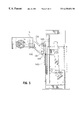
- FIGS. 10, 11 and 12 illustrate a preferred embodiment of the present invention.
- a detector head 305 of the nuclear camera 5 is supported between the two support arms 100 by a positioner 320 .
- the detector head 305 includes a casing 310 in which is contained a scintillation crystal and photomultiplier tubes. Attached to the underside of the casing 310 is a collimator plate 315 .
- the collimator plate 315 is made of lead perforated by narrow channels, and includes a collimator support 325 extending from the two edges of the collimator plate adjacent the support arms 100 .
- the collimator plate 315 is attached to the casing 310 by way of bolts 311 .
- the collimator plate 315 can be removed from the casing 310 and replaced by another collimator plate 315 .
- a particular design and weight of collimator is selected depending on the isotope being used or the type of study being conducted. Thus, the collimator plate 315 must be changed from time to time. Since the collimator plates 315 vary considerably in weight from one to another, the location of centre of gravity of the detector head 305 is dependent upon the weight of the collimator plate 315 attached to the casing 310 . Since the angle of the detector head 305 relative to the patient must be adjusted by an operator of the nuclear camera 5 , the detector head 305 must be rotatable relative to the arms 100 .
- the detector head 305 If the centre of gravity of the detector head 305 is positioned approximately on the axis of rotation of the detector head relative to the support arms 100 , then the detector head 305 will be balanced, and the angle of the detector head 305 relative to the support arms 100 will be adjustable by hand. However, changing the collimator plates moves the centre of gravity of the detector head. Since collimator plates 315 are so heavy, it becomes inconvenient or impossible to adjust the angle of the detector head 305 by hand.
- the positioner 320 enables the operator to adjust the position of the centre of gravity of the detector head 305 to be approximately aligned with the point of rotation of the detector head 305 , which passes through the support arms 100 .
- the positioner 320 attaches the detector head 305 to the support arms 100 and includes a pair of rigid elongate detector head links 330 for aligning the centre of gravity of the detector head 305 relative to the support arms 100 .
- Each detector head link 330 is rotatable relative to the support arms 100 in a plane substantially parallel to its adjacent support arm 100 .
- Each detector head link 330 includes an arm end 335 rotatably attached to the adjacent support arm 100 by way of an arm axle 340 .
- Each detector head link 330 also includes a head end 345 rotatably attached to the detector head 305 by way of a head axle 350 .
- the positioner 320 also includes a pair of locks 355 for selectively preventing rotation of the detector head 305 relative to the detector head links 330 .
- Each lock 355 includes the collimator support 325 extending 305 from the collimator plate 315 .
- Each lock 355 also includes a block 360 for supporting the detector head link 330 on the collimator support 325 .
- Each block 360 includes a pair of pins 365 located either side of the head axle 350 .
- each lock 355 supports the head end 345 of one of the detector head links 330 on the corresponding collimator support 325 .
- the distance between the head axle 350 and the collimator support 325 remains constant, and rotation of the detector head 305 relative to the detector head link 330 is prevented.
- the detector head 305 will be balanced, and the detector head 305 can be rotated manually by the operator. Once the detector head 305 has been rotated to the desired position relative to the support arms 100 , a brake (not shown) can be implemented to selectively prevent rotation of the detector head link about the arm axle 340 .
Abstract
A positioner for a scintillation camera detector head is designed for use with a detector head of the type having a center of gravity dependent upon the weight of a removable collimator plate and being supported between a pair of substantially parallel support arms such that the detector head is rotatable relative to the support arms about an axis of rotation passing through the support arms. The positioner includes a pair of rigid detector head links for aligning the center of gravity of the detector head relative to the support arms. Each detector head link includes an arm end rotatably attached to the adjacent support arm by way of an arm axle, and a head end rotatably attached to the detector head by way of a head axle. The positioner also includes a lock for selectively securing the relative positions of the detector head and the detector head links.
Description
The present invention relates to a centre of rotation adjustor for a scintillation camera detector head.
In the human body, increased metabolic activity is associated with an increase in emitted radiation. In the field of nuclear medicine, increased metabolic activity within a patient is detected using a radiation detector such as a scintillation camera.
Scintillation cameras are well known in the art, and are used for medical diagnostics. A patient ingests, or inhales or is injected with a small quantity of a radioactive isotope. The radioactive isotope emits photons that are detected by a scintillation medium in the scintillation camera. The scintillation medium is commonly a sodium iodide crystal, BGO or other. The scintillation medium emits a small flash or scintillation of light, in response to stimulating radiation, such as from a patient. The intensity of the scintillation of light is proportional to the energy of the stimulating photon, such as a gamma photon. Note that the relationship between the intensity of the scintillation of light and the gamma photon is not linear.
A conventional scintillation camera such as a gamma camera includes a detector which converts into electrical signals gamma rays emitted from a patient after radioisotope has been administered to the patient. The detector includes a scintillator and photomultiplier tubes. The gamma rays are directed to the scintillator which absorbs the radiation and produces, in response, a very small flash of light. An array of photodetectors, which are placed in optical communication with the scintillation crystal, converts these flashes into electrical signals which are subsequently processed. The processing enables the camera to produce an image of the distribution of the radioisotope within the patient.
Gamma radiation is emitted in all directions and it is necessary to collimate the radiation before the radiation impinges on the crystal scintillator. This is accomplished by a collimator which is a sheet of absorbing material, usually lead, perforated by relatively narrow channels. The collimator is detachably secured to the detector head, allowing the collimator to be changed to enable the detector head to be used with the different energies of isotope to suit particular characteristics of the patient study. A collimator may vary considerably in weight to match the isotope or study type.
Scintillation cameras are used to take four basic types of pictures: spot views, whole body views, partial whole body views, SPECT views, and whole body SPECT views.
A spot view is an image of a part of a patient. The area of the spot view is less than or equal to the size of the field of view of the gamma camera. In order to be able to achieve a full range of spot views, a gamma camera must be positionable at any location relative to a patient.
One type of whole body view is a series of spot views fitted together such that the whole body of the patient may be viewed at one time. Another type of whole body view is a continuous scan of the whole body of the patient. A partial whole body view is simply a whole body view that covers only part of the body of the patient. In order to be able to achieve a whole body view, a gamma camera must be positionable at any location relative to a patient in an automated sequence of views.
The acronym “SPECT” stands for single photon emission computerized tomography. A SPECT view is a series of slice-like images of the patient. The slice-like images are often, but not necessarily, transversely oriented with respect to the patient. Each slice-like image is made up of multiple views taken at different angles around the patient, the data from the various views being combined to form the slice-like image. In order to be able to achieve a SPECT view, a scintillation camera must be rotatable around a patient, with the direction of the detector head of the scintillation camera pointing in a series of known and precise directions such that reprojection of the data can be accurately undertaken.
A whole body SPECT view is a series of parallel slice-like transverse images of a patient. Typically, a whole body SPECT view consists of sixty four spaced apart SPECT views. A whole body SPECT view results from the simultaneous generation of whole body and SPECT image data. In order to be able to achieve a whole body SPECT view, a scintillation camera must be rotatable around a patient, with the direction of the detector head of the scintillation camera pointing in a series of known and precise directions such that reprojection of the data can be accurately undertaken.
Therefore, in order that the radiation detector be capable of achieving the above four basic views, the support structure for the radiation detector must be capable of positioning the radiation detector in any position relative to the patient. Furthermore, the support structure must be capable of moving the radiation detector relative to the patient in a controlled manner along any path.
The detector head of a scintillation camera includes a casing in which is contained the scintillator crystal and the photomultiplier tubes. Attached to the underside of the casing is a collimator or collimator plate, which is a sheet of absorbing material, usually lead, perforated by relatively narrow channels.
A particular design and weight of collimator must be selected depending on the isotope being used or the type of study being conducted. Thus, the collimator plate attached to the detector head must be changed from time to time. Collimator plates vary considerably in weight.
Generally, a detector head is supported by a pair of support arms. Since the angle of the detector head relative to the patient must be selectable, the detector head must be rotatable relative to the arms.
If a detector head is rotatable relative to the support arms at a point close to the centre of gravity of the detector head, then the angle of the detector head relative to a patient may be adjustable by hand. However, changing the collimator plates moves the centre of gravity of the detector head. Since collimator heads are so heavy, it becomes inconvenient or impossible to adjust the angle of the detector head by hand.
One prior art solution to the problem of adjusting the angle of a detector head is to provide an electric motor to adjust the angle of the detector head relative to the arms. However, the use of electric motors adds to the cost of manufacturing the machine. Furthermore, it is generally faster and more convenient to adjust the angle of the detector head by hand.
Another prior art solution is to adjust the point of rotation of the detector head relative to the support arms by providing lead screws driven by an electric motor. Again, the use of electric motors adds to the cost of manufacturing the machine. Furthermore, adjusting the point of rotation of the detector head using lead screws is time consuming.
An object of the invention is to provide an improved centre of rotation adjustor for a scintillation camera detector head.
A second object of the invention is to provide a centre of rotation adjustor for a scintillation camera detector head that is convenient to use.
A third object of the invention is to provide a centre of rotation adjustor for a scintillation camera detector head that avoids to use of a motor.
The invention relates to a positioner for a scintillation camera detector head. The detector head is of the type having a centre of gravity dependent upon the weight of a removable collimator plate and being supported by at least one support arm such that the detector head is rotatable relative to the support arm about an axis of rotation passing through the support arm. The positioner of the present invention includes a rigid detector head link for aligning the centre of gravity of the detector head relative to the support arm. The detector head link includes an arm end rotatably attached to the support arm. The detector head link also includes a head end rotatably attached to the detector head. The positioner also includes a lock for selectively securing the relative positions of the detector head and the detector head link.
An embodiment of the invention relates to a positioner for a scintillation camera detector head. The detector head is of the type having a centre of gravity dependent upon the weight of a removable collimator plate and being supported between a pair of substantially parallel support arms such that the detector head is rotatable relative to the support arms about an axis of rotation passing through the support arms. The positioner includes a pair of rigid elongate detector head links for aligning the centre of gravity of the detector head relative to the support arms. Each detector head link is substantially parallel to an adjacent support arm. Each detector head link includes an arm end rotatably attached to the adjacent support arm by way of an arm axle. Each detector head link also includes a head end rotatably attached to the detector head by way of a head axle. The positioner also includes a pair of locks for selectively preventing rotation of the detector head relative to the detector head links. Each lock includes a collimator support extending from the detector head adjacent the collimator plate. Each lock also includes a block for supporting the detector head link on the collimator support. Each block includes a pair of pins located either side of the head axle.
According to the invention, there is provided a positioner for a scintillation camera detector head, the detector head having a centre of gravity dependent upon the weight of a removable collimator plate and being supported by at least one support arm such that the detector head is rotatable relative to the support arm about an axis of rotation passing through the support arm, the positioner comprising: a rigid detector head link for aligning the centre of gravity of the detector head relative to the support arm, the detector head link comprising: an arm end rotatably attached to the support arm; and a head end rotatably attached to the detector head; and a lock for selectively securing the relative positions of the detector head and the detector head link.
According to the invention, there is further provided a positioner for a scintillation camera detector head, the detector head having a centre of gravity dependent upon the weight of a removable collimator plate and being supported between a pair of substantially parallel support arms such that the detector head is rotatable relative to the support arms about an axis of rotation passing through the support arms, the positioner comprising: a pair of rigid elongate detector head links for aligning the centre of gravity of the detector head relative to the support arms, each detector head link being substantially parallel to an adjacent support arm and comprising; an arm end rotatably attached to the adjacent support arm by way of an arm axle; and a head end rotatably attached to the detector head by way of a head axle; and a pair of locks for selectively preventing rotation of the detector head relative to the detector head links, each lock comprising: a collimator support extending from the detector head adjacent the collimator plate; and a block for supporting the detector head link on the collimator support, each block comprising a pair of pins located either side of the head axle.
Advantageously, the present invention provides: an improved centre of rotation adjustor for a scintillation camera detector head; a centre of rotation adjustor for a scintillation camera detector head that is convenient to use; and a centre of rotation adjustor for a scintillation camera detector head that avoids to use of a motor.
Other advantages, objects and features of the present invention will be readily apparent to those skilled in the art from a review of the following detailed description of preferred embodiments in conjunction with the accompanying drawings and claims.
The embodiments of the invention will now be described with reference to the accompanying drawings, in which:
FIG. 1 is a perspective view of a scintillation camera including a detached patient support in accordance with the invention;
FIG. 2 is a perspective view of the guide of a scintillation camera;
FIG. 3 is a front elevation view of a scintillation camera;
FIG. 4 is a side elevation view of a scintillation camera;
FIG. 5 is a side elevation view of a scintillation camera;
FIG. 6 is a front elevation view of a scintillation camera;
FIG. 7 is a top plan view of a scintillation camera;
FIG. 8 is a perspective view of the scintillation camera of FIG. 1, including the detached patient support and engaged patient support, with the stretcher removed;
FIG. 9 is a side view of a portion of the patient support apparatus;
FIG. 10 is a perspective view of the positioner of the present invention;
FIG. 11 is a side elevation view of the positioner of the present invention; and
FIG. 12 is a front elevation view of the positioner of the present invention.
Similar references are used in different figures to denote similar components.
Referring to FIGS. 1 to 12, a nuclear camera 5 is supported and positioned relative to a patient by a support structure 10. Nuclear cameras are heavy, usually weighing approximately three to four thousand pounds. Thus, the support structure 10 should be strong and stable in order to be able to position the camera 5 safely and accurately. The support structure 10 includes a base 15, an annular support 20, an elongate support 25, and a guide 30.
The base 15 includes a frame 35. The frame 35 includes twelve lengths of square steel tubing welded together in the shape of a rectangular parallelepiped. The frame 35 has a front square section 37 and a rear square section 38. In the illustrated embodiment, the frame 35 is approximately five feet wide, five feet high, and two feet deep. The frame 35 also includes eight triangular corner braces 40 welded to the front square section 37, that is, each corner of the front square section 37 has two corner braces 40, one towards the front of the front square section 37, and one towards the rear of the front square section 37. In the illustrated embodiment, the corner braces 40 are in the shape of equilateral right angle triangles.
Attached to the underside of the frame 35 are two horizontal legs 45. Attached to each leg 45 are two feet 50. An alternative to the use of feet 50 is to attach the base 15 to a floor by way of bolts set into the floor. The legs 45 extend beyond the frame 35 so as to position the feet 50 wider apart to increase the stability of the base 15. The feet 50 are adjustable so that the base 15 may be levelled. Thus constructed, the base 15 is strong, stable, rigid, and capable of supporting heavy loads.
The annular support 20 is vertically oriented, having an inner surface 55 defining an orifice 60, an outer surface 65, a front surface 70, and a rear surface 75. The annular support 20 is constructed of a ductile iron casting capable of supporting heavy loads. In the illustrated embodiment, the annular support 20 has an outside diameter of about fifty two inches (about 132 centimeters). The annular support 20 is supported by upper rollers 80 and lower rollers 85 which are mounted on the base 15. The upper rollers 80 and lower rollers 85 roll on the outer surface 65, thus enabling the annular support 20 to rotate relative to the base 15 in the plane defined by the annular support 20. Each of the upper rollers 80 and lower rollers 85 are mounted onto a pair of corner braces 40 by way of axles with deep groove bearings. The bearings should be low friction and be able to withstand heavy loads. The axles of the upper rollers 80 are radially adjustable relative to the annular support 20, so that the normal force exerted by the upper rollers 80 on the outer surface 65 is adjustable. The curved surfaces of the upper rollers 80 and lower rollers 85 (i.e. the surfaces that contact the outer surface 65) should be tough so as to be able to withstand the pressures exerted by the annular support 20, and should have a fairly high coefficient of friction so as to roll consistently relative to the annular support 20.
Attached to each pair of corner braces 40 is a stabilizing arm (not shown) oriented perpendicularly to the plane of the annular support 20. A pair of small stabilizing rollers are mounted (not shown) onto each stabilizing arm. Each pair of stabilizing rollers is positioned such that one stabilizing roller rolls on the front surface 70, and the other stabilizing roller rolls on the rear surface 75. The stabilizing rollers maintain the annular support 20 in the vertical plane.
The elongate support 25 includes a pair of support arms 100, each of which extends through an aperture in the annular support 20. The nuclear camera 5 is rotatably attached to one end of the pair of support arms 100, such that the nuclear camera 5 faces the front surface 70. A counter weight 105 is attached to the other end of the pair of support arms 100, such that the counterweight 105 faces the rear surface 75.
The counter weight 105 includes a pair of parallel counter weight members 110, each of which is pivotally attached to one of the support arms 100. A first weight 115 is attached to one end of the pair of counter weight members 110, and a second weight 120 is attached to the other end of the pair of counter weight members 110. A pair of counter weight links 121 connect the counter weight members 110 to the annular support 20. Each counter weight link 121 is pivotally attached at one end to its corresponding counter weight member 110. Each counter weight link 121 is pivotally attached at its other end to a counter weight bracket 122 which is rigidly attached to the annular support 20. The counter weight links 121 are attached to the counterweight members 110 and counter weight brackets 122 using bolts and tapered roller bearings. Each counter weight link 121 is pivotable relative to the annular support 20 in a plane perpendicular to and fixed relative to the annular support 20.
The guide 30 attaches the elongate support 25 to the annular support 20, and controls the position of the elongate support 25, and hence the scintillation camera 5, relative to the annular support 20. A pair of brackets 125 is rigidly attached to the annular support 20. A pair of rigid links 130 is pivotally attached at support arm pivot points 135 to the support arms 100. The pair of links 130 is also pivotally attached at bracket pivot points 140 to the brackets 125. At the support arm pivot points 135 and bracket pivot points 140 are tapered roller bearings mounted with bolts. Each link 130 is pivotable relative to the annular support 20 in a plane perpendicular to and fixed relative to the annular support 20. Thus, as the annular support 20 rotates relative to the base 15, the respective planes in which each link 130 and each support arm 100 can move remain fixed relative to the annular support 20.
A pair of linear tracks 145 are rigidly attached to the front surface 70 of the annular support 20. The tracks 145 are oriented such that they are parallel to the respective planes in which each link 130 and each support arm 100 can move. A pair of rigid sliding arms 150 (not shown in FIG. 1) include camera ends 155 and straight ends 160. Each camera end 155 is pivotally attached to one of the support arms 100 at the point of attachment of the scintillation camera 5. Each straight end 160 includes a pair of spaced apart cam followers or guides 165 slidable within the corresponding track 145. Thus, movement of the scintillation camera 5 relative to the annular support 20 (i.e. we are not concerned, at this point, with rotational movement of the scintillation camera 5 relative to the elongate support 25) is linear and parallel to the plane of the annular support 20. Note that if the camera ends 155 were pivotally attached to the support arms 100 between the nuclear camera 5 and the annular support 20, the movement of the nuclear camera 5 relative to the annular support 20 would not be linear.
Movement of the scintillation camera 5 relative to the annular support 20 is effected by an actuator 170. The actuator 170 includes a fixed end 175 pivotally attached to the annular support 20, and a movable end 180 pivotally attached to the elongate support 25. The actuator 170 is extendable and retractable, and is thus able to move the elongate support 25 relative to the annular support 20.
Movement of the annular support 20 relative to the base 15 is effected by a drive unit 185. The drive unit 185 includes a quarter horsepower permanent magnet DC motor and a gearbox to reduce the speed of the output shaft of the drive unit 185. Alternatively, other types of motors could be used, such as hydraulic or pneumatic motors. The output shaft of the drive unit 185 is coupled, by means of a toothed timing belt 195 and two pulley wheels 200, to the axle of a drive roller 190, which is simply one of the lower rollers 85, thus driving the drive roller 190. Power is then transferred from the drive roller 190 to the annular support 20 by friction between the drive roller 190 and the outer surface 65 of the annular support 20.
The support structure 10 of the illustrated embodiment is designed to operate with an apparatus for supporting and positioning a patient, such apparatus including a detached patient support 205, an engaged patient support 210, and a cylinder 245.
The detached patient support 205 includes rigid patient frame 215 supported by four casters 220. Mounted near the top of the patient frame 215 are first support wheels 225 for supporting a stretcher 227 upon which a patient is lying. Two parallel, spaced apart side rails 230 are rigidly attached to the patient frame 215. The first support wheels 225 and the side rails 230 are arranged to enable the stretcher 227 to roll lengthwise on the detached patient support 205. Thus, if the patient support 205 faces the front surface 70 such that the patient support is central and perpendicular relative to the annular support 20, the stretcher 227 is movable on the first patient support wheels 225 substantially along the axis of the annular support 20. A gear box and motor unit 237 driving at least one of the first patient support wheels 225 moves the stretcher 227 as described. A 0.125 horsepower permanent magnet DC motor has been found to be adequate.
The detached patient support 205 can be used both for transporting a patient to and from the scintillation camera 5 and support structure 10 therefor, and for supporting and positioning a patient relative to the base 15 during operation of the scintillation camera 5 and support structure 10. To ensure that the detached patient support 205 remains stationary during operation of the scintillation camera 5, four stabilizers 233 can be lowered. Thus lowered, the stabilizers 233 ensure that the detached patient support remains stationary relative to the floor.
The engaged patient support 210 includes second support wheels 235. The second support wheels 235 are positioned such that the stretcher 227 rolled along the first support wheels 225 can roll onto the second support wheels 235 until the stretcher 227 is either fully or partially supported by the second support wheels 235. The engaged patient support 210 also includes four transverse wheels 240.
The cylinder 245 is rigidly mounted to the annular support 20. The cylinder 245 is aligned with the orifice 60 of the annular support 20 such that the cylinder is coaxial with the annular support 20. The cylinder 245 includes a smooth inner surface 246 upon which rest the transverse wheels 240 of the engaged patient support 210. Thus, the arrangement is such that the patient remains stationary substantially along the axis of the annular support 20 as the annular support 20 rotates relative to the base 15, regardless of whether the board or stretcher is supported by the first support wheels 225, the second support wheels 235, or both.
The engaged patient support 210 also includes a stabilizer 250. The stabilizer 250 includes outside wheels 255 to maintain the engaged patient support 210 horizontal, that is, to stop the engaged patient support from tipping relative to the cylinder 245. The outside wheels 255 roll on the outside surface 243 of the cylinder 250. The stabilizer 245 also includes end wheels 256 to prevent the engaged patient support 210 from moving in a direction parallel to the axis of the cylinder 215. The end wheels 256 roll on the ends 244 of the cylinder 245.
FIGS. 10, 11 and 12 illustrate a preferred embodiment of the present invention. A detector head 305 of the nuclear camera 5 is supported between the two support arms 100 by a positioner 320. The detector head 305 includes a casing 310 in which is contained a scintillation crystal and photomultiplier tubes. Attached to the underside of the casing 310 is a collimator plate 315. The collimator plate 315 is made of lead perforated by narrow channels, and includes a collimator support 325 extending from the two edges of the collimator plate adjacent the support arms 100. The collimator plate 315 is attached to the casing 310 by way of bolts 311. By removing the bolts 311, the collimator plate 315 can be removed from the casing 310 and replaced by another collimator plate 315. A particular design and weight of collimator is selected depending on the isotope being used or the type of study being conducted. Thus, the collimator plate 315 must be changed from time to time. Since the collimator plates 315 vary considerably in weight from one to another, the location of centre of gravity of the detector head 305 is dependent upon the weight of the collimator plate 315 attached to the casing 310. Since the angle of the detector head 305 relative to the patient must be adjusted by an operator of the nuclear camera 5, the detector head 305 must be rotatable relative to the arms 100. If the centre of gravity of the detector head 305 is positioned approximately on the axis of rotation of the detector head relative to the support arms 100, then the detector head 305 will be balanced, and the angle of the detector head 305 relative to the support arms 100 will be adjustable by hand. However, changing the collimator plates moves the centre of gravity of the detector head. Since collimator plates 315 are so heavy, it becomes inconvenient or impossible to adjust the angle of the detector head 305 by hand. The positioner 320 enables the operator to adjust the position of the centre of gravity of the detector head 305 to be approximately aligned with the point of rotation of the detector head 305, which passes through the support arms 100.
The positioner 320 attaches the detector head 305 to the support arms 100 and includes a pair of rigid elongate detector head links 330 for aligning the centre of gravity of the detector head 305 relative to the support arms 100. Each detector head link 330 is rotatable relative to the support arms 100 in a plane substantially parallel to its adjacent support arm 100. Each detector head link 330 includes an arm end 335 rotatably attached to the adjacent support arm 100 by way of an arm axle 340. Each detector head link 330 also includes a head end 345 rotatably attached to the detector head 305 by way of a head axle 350.
The positioner 320 also includes a pair of locks 355 for selectively preventing rotation of the detector head 305 relative to the detector head links 330. Each lock 355 includes the collimator support 325 extending 305 from the collimator plate 315. Each lock 355 also includes a block 360 for supporting the detector head link 330 on the collimator support 325. Each block 360 includes a pair of pins 365 located either side of the head axle 350.
In operation, each lock 355 supports the head end 345 of one of the detector head links 330 on the corresponding collimator support 325. Thus, the distance between the head axle 350 and the collimator support 325 remains constant, and rotation of the detector head 305 relative to the detector head link 330 is prevented.
If a heavier collimator plate 315 is installed, shorter pins 365 are installed, thus reducing the distance between the head axle 350 and the collimator support 325, and aligning the centre of gravity of the detector head 305 with the axis of rotation of the detector head 305, which passes through the arm axles 340.
If a lighter collimator plate 315 is installed, longer pins 365 are installed, thus increasing the distance between the head axle 350 and the collimator support 325, and aligning the centre of gravity of the detector head 305 with the axis of rotation of the detector head 305, which passes through the arm axles 340.
Once the locks 355 are in place, the detector head 305 will be balanced, and the detector head 305 can be rotated manually by the operator. Once the detector head 305 has been rotated to the desired position relative to the support arms 100, a brake (not shown) can be implemented to selectively prevent rotation of the detector head link about the arm axle 340.
Numerous modifications, variations and adaptations may be made to the particular embodiments of the invention described above without departing from the scope of the invention, which is defined in the claims.
Claims (7)
1. A positioner for a scintillation camera detector head, the detector head having a centre of gravity dependent upon the weight of a removable collimator plate and being supported by at least one support arm such that the detector head is rotatable relative to the support arm about an axis of rotation passing through the support arm, the positioner comprising:
(a) a rigid detector head link comprising:
(i) an arm end rotatably attached to the support arm by way of an arm axle defining a first axis of rotation for adjusting the angle of the detector head relative to the support arm; and
(ii) head end rotatably attached to the detector head by way of a head axle defining a second axis of rotation for positioning the centre of gravity of the detector head relative to the first axis of rotation; and
(b) a lock for selectively securing the relative positions of the detector head and the detector head link.
2. A positioner for a scintillation camera detector head, the detector head having a centre of gravity dependent upon the weight of a removable collimator plate and being supported between a pair of substantially parallel adjacent support arms such that the detector head is rotatable relative to the support arms about an axis of rotation passing through the support arms, the positioner comprising:
(a) a pair of rigid detector head links for aligning the centre of gravity of the detector head relative to the support arms, each detector head link comprising:
(i) an arm end rotatably attached to the adjacent support arm by way of an arm axle defining a first axis of rotation for adjusting the angle of the detector head relative to the support arm; and
(ii) a head end rotatably attached to the detector head by way of a head axle defining a second axis of rotation for positioning the centre of gravity of the detector head relative to the first axis of rotation; and
(b) a lock for selectively securing the relative positions of the detector head and the detector head links.
3. A positioner as defined in claim 2, wherein each rigid link is elongate and is substantially parallel to an adjacent support arm.
4. A positioner as defined in claim 2, comprising a pair of locks for selectively preventing rotation of the detector head relative to the detector head links.
5. A positioner as defined in claim 2, the lock comprising:
(a) a collimator support extending from the detector head adjacent the collimator plate; and
(b) a block for supporting the detector head link on the collimator support.
6. A positioner as defined in claim 5, each block comprising a pair of pins located either side of the head axle.
7. A positioner for a scintillation camera detector head, the detector head having a centre of gravity dependent upon the weight of a removable collimator plate and being supported between a pair of substantially parallel support arms such that the detector head is rotatable relative to the support arms about an axis of rotation passing through the support arms, the positioner comprising:
(a) a pair of rigid elongated detector head links for aligning the centre of gravity of the detector head relative to the support arms, each detector head link being substantially parallel to an adjacent support arm and comprising;
(i) an arm end rotatably attached to the adjacent support arm by way of an arm axle; and
(ii) a head end rotatably attached to the detector head by way of a head axle; and
(b) a pair of locks for selectively preventing rotation of the detector head relative to the detector head links, each lock comprising;
(i) a collimator support extending from the detector head adjacent the collimator plate; and
(ii) a block for supporting the detector head link on the collimator support, each block adapted to receive a pair of removable fixed length pins located either side of the head axle, wherein the pins installed are exchangeable with pins of a different length dependent on the weight of the collimator plate installed.
Applications Claiming Priority (2)
| Application Number | Priority Date | Filing Date | Title |
|---|---|---|---|
| CA002212196A CA2212196A1 (en) | 1997-08-01 | 1997-08-01 | Medical diagnostic apparatus and method |
| CA2212196 | 1997-08-01 |
Publications (1)
| Publication Number | Publication Date |
|---|---|
| US6255656B1 true US6255656B1 (en) | 2001-07-03 |
Family
ID=4161179
Family Applications (6)
| Application Number | Title | Priority Date | Filing Date |
|---|---|---|---|
| US09/127,982 Expired - Fee Related US6255656B1 (en) | 1997-08-01 | 1998-08-03 | Positioner for a scintillation camera detector head |
| US09/127,987 Expired - Fee Related US6175119B1 (en) | 1997-08-01 | 1998-08-03 | Photomultiplier tube identifier |
| US09/127,985 Expired - Fee Related US6044504A (en) | 1997-08-01 | 1998-08-03 | Patient support for a scintillation camera |
| US09/127,990 Expired - Fee Related US6342698B1 (en) | 1997-08-01 | 1998-08-03 | Method for calibrating photomultiplier tubes in a scintillation camera |
| US09/127,989 Expired - Fee Related US6288398B1 (en) | 1997-08-01 | 1998-08-03 | Support structure for medical diagnostic equipment |
| US09/931,169 Expired - Fee Related US6639220B2 (en) | 1997-08-01 | 2001-08-17 | Data reducer for a scintillation camera |
Family Applications After (5)
| Application Number | Title | Priority Date | Filing Date |
|---|---|---|---|
| US09/127,987 Expired - Fee Related US6175119B1 (en) | 1997-08-01 | 1998-08-03 | Photomultiplier tube identifier |
| US09/127,985 Expired - Fee Related US6044504A (en) | 1997-08-01 | 1998-08-03 | Patient support for a scintillation camera |
| US09/127,990 Expired - Fee Related US6342698B1 (en) | 1997-08-01 | 1998-08-03 | Method for calibrating photomultiplier tubes in a scintillation camera |
| US09/127,989 Expired - Fee Related US6288398B1 (en) | 1997-08-01 | 1998-08-03 | Support structure for medical diagnostic equipment |
| US09/931,169 Expired - Fee Related US6639220B2 (en) | 1997-08-01 | 2001-08-17 | Data reducer for a scintillation camera |
Country Status (2)
| Country | Link |
|---|---|
| US (6) | US6255656B1 (en) |
| CA (1) | CA2212196A1 (en) |
Cited By (3)
| Publication number | Priority date | Publication date | Assignee | Title |
|---|---|---|---|---|
| US6444987B1 (en) * | 1998-11-27 | 2002-09-03 | Sopha Medical Vision International | Gamma camera usable in two positions of a patient |
| US20140116226A1 (en) * | 2012-10-29 | 2014-05-01 | Yamaha Corporation | Electric stringed instrument |
| DE102017111296B3 (en) | 2017-05-23 | 2018-08-02 | Medineering Gmbh | Robotic manipulator for guiding an endoscope with parallel kinematics |
Families Citing this family (34)
| Publication number | Priority date | Publication date | Assignee | Title |
|---|---|---|---|---|
| US6521893B2 (en) * | 1997-08-01 | 2003-02-18 | Is2 Research Inc. | Method and apparatus for improving image quality in positron emission tomography |
| US6208542B1 (en) * | 1998-06-30 | 2001-03-27 | Sandisk Corporation | Techniques for storing digital data in an analog or multilevel memory |
| US6484332B2 (en) * | 1999-12-08 | 2002-11-26 | Med-Tec Iowa, Inc. | System for vertical to horizontal movement and lateral movement of a patient |
| US6603125B1 (en) * | 2000-06-02 | 2003-08-05 | Koninklijke Philips Electronics, N.V. | Event localization and fall-off correction by distance-dependent weighting |
| US6949747B2 (en) * | 2000-06-02 | 2005-09-27 | Is2 Medical Systems Inc. | Apparatus and method for automatically adjusting the path of a medical camera |
| GB0109634D0 (en) * | 2001-04-19 | 2001-06-13 | Univ Southampton | An ultra-fast high resolution pet detector |
| US6810103B1 (en) * | 2001-07-16 | 2004-10-26 | Analogic Corporation | Gantry for combined tomography scanner |
| DE10206173B4 (en) * | 2002-02-14 | 2006-08-31 | Bruker Daltonik Gmbh | High-resolution detection for time-of-flight mass spectrometers |
| US6861321B2 (en) * | 2002-04-05 | 2005-03-01 | Asm America, Inc. | Method of loading a wafer onto a wafer holder to reduce thermal shock |
| FR2841456B1 (en) * | 2002-06-26 | 2005-06-03 | Sopha Medical Vision Internat | NUCLEAR MEDICINE MACHINE WITH A FIRING BED AND USE THEREOF |
| US6835935B2 (en) * | 2002-08-21 | 2004-12-28 | Siemens Medical Solutions Usa, Inc. | System and method for calibrating and tuning a gamma camera |
| US7945021B2 (en) | 2002-12-18 | 2011-05-17 | Varian Medical Systems, Inc. | Multi-mode cone beam CT radiotherapy simulator and treatment machine with a flat panel imager |
| US7071474B2 (en) * | 2002-12-20 | 2006-07-04 | Board Of Regents, The University Of Texas System | Methods and apparatus for tuning scintillation detectors |
| ES2534827T3 (en) * | 2003-04-07 | 2015-04-29 | Supernus Pharmaceuticals, Inc. | Tetracycline formulations in single daily dose |
| US7357575B2 (en) * | 2003-09-17 | 2008-04-15 | Koninklijke Philips Electronics N.V. | Telescoping table |
| US20050176252A1 (en) * | 2004-02-10 | 2005-08-11 | Goodman Matthew G. | Two-stage load for processing both sides of a wafer |
| US7297957B1 (en) | 2004-04-09 | 2007-11-20 | Gvi Technology Partners, Ltd. | Apparatus and method for gain calibration of a radiation detector |
| US7638760B1 (en) | 2004-05-28 | 2009-12-29 | Gvi Technology Partners, Ltd. | Method for tracking and correcting the baseline of a radiation detector |
| US8014850B2 (en) * | 2004-07-01 | 2011-09-06 | Gvi Technology Partners, Ltd. | Initiation of dynamic data acquisition |
| US7502500B2 (en) * | 2004-09-30 | 2009-03-10 | Gvi Technology Partners, Ltd. | Automated processing of dynamic cardiac acquisition data |
| US8231414B2 (en) * | 2004-10-04 | 2012-07-31 | Gvi Technology Partners, Ltd. | Sensor interconnect system |
| JP5192378B2 (en) * | 2005-08-04 | 2013-05-08 | コーニンクレッカ フィリップス エレクトロニクス エヌ ヴィ | Modular signal processing backbone for PET |
| US7612343B2 (en) * | 2006-10-16 | 2009-11-03 | Gvi Medical Devices | Collimator for radiation detectors and method of use |
| EP2133713A1 (en) * | 2008-06-13 | 2009-12-16 | Vrije Universiteit Brussel | Method, device and system for localizing an interaction point |
| DE102011083381A1 (en) * | 2011-09-26 | 2013-03-28 | Siemens Aktiengesellschaft | Medical imaging device |
| US10591416B2 (en) | 2013-02-22 | 2020-03-17 | Life Technologies Corporation | Optical systems and methods for biological analysis |
| US9618629B2 (en) | 2014-11-25 | 2017-04-11 | Jens Hovgaard | Apparatus and method for monitoring performance of radiation detector |
| US9903961B1 (en) * | 2016-09-01 | 2018-02-27 | FMI Medical Systems Co., Ltd. | Photodetector array readout multiplexer having summing, pulse shaping, and dynamic-switching circuits |
| CN110152202A (en) * | 2018-02-01 | 2019-08-23 | 青岛大学附属医院 | A kind of clinical therapy of tumor equipment and its application method |
| JP6878330B2 (en) * | 2018-02-09 | 2021-05-26 | 株式会社東芝 | Particle therapy device |
| DE202018103733U1 (en) * | 2018-06-29 | 2018-08-16 | Medical Intelligence Medizintechnik Gmbh | Radiotherapy System |
| CN111198211B (en) * | 2018-11-16 | 2022-01-25 | 中国科学院大连化学物理研究所 | Movable imaging device based on capacitive tomography sensor |
| CN111554424B (en) * | 2020-05-12 | 2022-04-15 | 武汉第二船舶设计研究所(中国船舶重工集团公司第七一九研究所) | Nuclear power station reactor protection system |
| US11675098B1 (en) | 2021-11-03 | 2023-06-13 | National Technology & Engineering Solutions Of Sandia, Llc | Systems and methods for in-situ calibration of scintillation spectrometer |
Citations (13)
| Publication number | Priority date | Publication date | Assignee | Title |
|---|---|---|---|---|
| US3765549A (en) | 1971-10-21 | 1973-10-16 | Transfer Systems | Apparatus and method for loading nuclear fuel into a shipping cask without immersion in a pool |
| US4064441A (en) | 1975-04-17 | 1977-12-20 | Ital Elettronica S.P.A. | Scanning device for scintigraphy of the human body |
| US4216381A (en) | 1979-05-10 | 1980-08-05 | General Electric Company | Structure for emission tomography scintillation camera |
| US4223222A (en) | 1978-09-28 | 1980-09-16 | General Electric Company | Suspended arm for a scintillation camera |
| US4426578A (en) * | 1980-10-08 | 1984-01-17 | Technicare Corporation | Support structure for rotatable scintillation detector |
| US4578585A (en) * | 1983-11-25 | 1986-03-25 | Siemens Gammasonics, Inc. | Detector head mounting mechanism |
| US4590378A (en) * | 1984-06-04 | 1986-05-20 | Siemens Gammasonics, Inc. | Counterbalanced radiation detection device |
| US4651007A (en) | 1984-09-13 | 1987-03-17 | Technicare Corporation | Medical diagnostic mechanical positioner |
| US4774411A (en) * | 1986-11-07 | 1988-09-27 | U.S. Philips Corporation | Gamma tomography apparatus |
| US5047641A (en) | 1990-03-14 | 1991-09-10 | Siemens Gammasonics, Inc. | Scintillation camera with automatically counterbalanced gantry |
| US5146094A (en) | 1991-06-07 | 1992-09-08 | Isis Inc. | Medical diagnostic nuclear camera system |
| US5262648A (en) | 1993-02-10 | 1993-11-16 | Independent Scintillation Imaging Systems (Isis) Inc. | Medical diagnostic nuclear camera fork mounting with offset |
| US5523571A (en) * | 1995-03-31 | 1996-06-04 | Siemens Medical Systems, Inc. | Versatile reconfigurable gantry for use in scintillation camera systems |
Family Cites Families (48)
| Publication number | Priority date | Publication date | Assignee | Title |
|---|---|---|---|---|
| US3011057A (en) | 1958-01-02 | 1961-11-28 | Hal O Anger | Radiation image device |
| US3050745A (en) * | 1960-11-21 | 1962-08-28 | Tabbert Mfg Company | Hospital stretcher |
| US3171763A (en) | 1963-02-21 | 1965-03-02 | Nippon Electric Co | Method for making silicon semiconductor devices |
| FR2168849B1 (en) | 1972-01-24 | 1976-09-03 | Schlumberger Prospection | |
| US3911278A (en) * | 1972-07-05 | 1975-10-07 | Ohio Nuclear | Radiation sensing device |
| US3777161A (en) * | 1972-11-08 | 1973-12-04 | Atomic Energy Commission | Hodoscope readout system |
| US4060730A (en) | 1973-09-07 | 1977-11-29 | Elscint, Ltd. | Scintillation camera for establishing the coordinates of a radiation stimuli produced by a radiation field |
| US3914611A (en) | 1973-11-21 | 1975-10-21 | Raytheon Co | Gamma camera |
| FR2286393A1 (en) | 1974-09-27 | 1976-04-23 | Labo Electronique Physique | AUTOMATIC PERMANENT CALIBRATION SYSTEM FOR SCINTILLATION CAMERA |
| FR2328207A1 (en) | 1975-10-17 | 1977-05-13 | Labo Electronique Physique | AUTOMATIC REGULATION SYSTEM FOR SCINTILLATION CAMERA |
| GB1554115A (en) * | 1976-06-28 | 1979-10-17 | Ohio Nuclear | Patient support systems |
| DE2826484C2 (en) | 1978-06-16 | 1982-08-26 | Laboratorium Prof. Dr. Rudolf Berthold, 7547 Wildbad | Control method for automatic drift stabilization during radiation measurement and uses in this method |
| JPS5759183A (en) | 1980-09-26 | 1982-04-09 | Toshiba Corp | Scintillation camera and its adjusting method |
| DK230481A (en) | 1981-05-26 | 1982-11-27 | Gen Electric Nuclear Medical A | DEVICE BY AN OLD CAMERA FOR AUTOMATIC REINFORCEMENT CONTROL |
| NL8102616A (en) * | 1981-05-29 | 1982-12-16 | Philips Nv | GAMMATOMOGRAPH WITH PARALLELOGRAM SUSPENSION. |
| NL8103058A (en) | 1981-06-24 | 1983-01-17 | Philips Nv | METHOD FOR CALIBRATING A GAMMA CAMERA AND GAMMA CAMERA WITH A CALIBRATION DEVICE |
| US4497024A (en) | 1981-07-01 | 1985-01-29 | General Electric Company | Nuclear image display controller |
| US4583187A (en) | 1983-02-02 | 1986-04-15 | Siemens Gammasonics, Inc. | Method and circuit for stabilizing conversion gain of radiation detectors of a radiation detection system |
| DE3328256C2 (en) | 1983-08-04 | 1986-08-28 | Endress U. Hauser Gmbh U. Co, 7867 Maulburg | Method and arrangement for the automatic stabilization of a scintillation detector |
| CA1219086A (en) | 1983-08-19 | 1987-03-10 | Kazuhiro Iinuma | Radiation imaging apparatus |
| US4605856A (en) | 1983-11-09 | 1986-08-12 | Siemens Gammasonics, Inc. | Method and device for stabilizing photomultiplier tubes of a radiation image device against drift |
| US4652758A (en) * | 1984-06-04 | 1987-03-24 | General Electric Company | Nuclear imaging tomography |
| JPS61162782A (en) | 1985-01-12 | 1986-07-23 | Hitachi Medical Corp | Scintillation camera |
| US4671728A (en) * | 1985-07-11 | 1987-06-09 | Applied Power, Inc. | Hydraulic system for a mobile transport vehicle that supports and positions a load relative to a docking structure |
| US4780823A (en) | 1986-03-11 | 1988-10-25 | Siemens Gammasonics, Inc. | Multiple pixel area-weighted acquisition system for scintillation cameras |
| EP0252566B1 (en) | 1986-07-09 | 1991-04-24 | Laboratoires D'electronique Philips | Scintillation camera |
| EP0280731B1 (en) | 1986-08-28 | 1992-07-22 | Shimadzu Corporation | Amplification degree stabilizer for photomultiplier tubes |
| FR2605745B1 (en) | 1986-10-24 | 1990-11-09 | Labo Electronique Physique | SCINTILLATION CAMERA |
| FR2615960B1 (en) | 1987-05-27 | 1991-09-06 | Commissariat Energie Atomique | NUCLEAR RADIATION LOCATION DEVICE, AND RADIATION IMAGE FORMING DEVICE INCLUDING SUCH LOCATION DEVICE |
| US5004904A (en) | 1988-06-17 | 1991-04-02 | Kabushiki Kaisha Toshiba | Method and system for controlling gain and offset in radiation measurement apparatus |
| DE69115968D1 (en) | 1990-03-30 | 1996-02-15 | Siemens Ag | Scintillation camera device and method of applying an algorithm for position determination |
| JPH0627828B2 (en) | 1991-02-27 | 1994-04-13 | 浜松ホトニクス株式会社 | Position detector |
| FR2677447A1 (en) * | 1991-06-07 | 1992-12-11 | Sopha Medical | GAMMA TOMOGRAPHIC CAMERA PROVIDED WITH AN ORIENTABLE DETECTOR. |
| JPH05203749A (en) | 1991-08-28 | 1993-08-10 | Siemens Ag | Position checking method of multiple scintillation event |
| DE59102128D1 (en) | 1991-09-11 | 1994-08-11 | Siemens Ag | Procedure for fast location using the maximum likelihood estimator for a gamma camera. |
| US5349190A (en) * | 1991-12-02 | 1994-09-20 | Adac Laboratories | Adjustable triple-detector image data acquisition system |
| US5309357A (en) | 1992-01-28 | 1994-05-03 | Independent Scintillation Imaging Systems (Isis) Inc. | Scintillation data collecting apparatus and method |
| US5237173A (en) | 1992-04-01 | 1993-08-17 | Independent Scintillation Imaging Systems, Inc. | Gain calibration in a scintillation camera |
| US5576546A (en) * | 1992-10-28 | 1996-11-19 | Park Medical Systems Inc. | Depth-of-interaction normalization of signals for improved positioning, and energy resolution in scintillation camera |
| FR2700859B1 (en) * | 1993-01-27 | 1995-03-31 | Sopha Medical | Gain compensation gamma camera. |
| GB9314398D0 (en) | 1993-07-12 | 1993-08-25 | Gen Electric | Signal processing in scintillation cameras for nuclear medicine |
| JP3532942B2 (en) * | 1993-08-04 | 2004-05-31 | 浜松ホトニクス株式会社 | Radiation position detector |
| EP1104890A3 (en) * | 1994-10-04 | 2002-10-30 | Adac Laboratories | Gamma camera system |
| US5717212A (en) * | 1996-04-25 | 1998-02-10 | Picker International, Inc. | Three detector head gamma camera system with independently circumferentially positionable detector heads |
| US5808468A (en) * | 1996-12-13 | 1998-09-15 | Bis; Kostaki G. | Universal kinematic imaging table for rapid positional changes in patient centering |
| US5866906A (en) * | 1997-05-30 | 1999-02-02 | General Electric Company | Gamma detector locking mechanism |
| US5960054A (en) * | 1997-11-26 | 1999-09-28 | Picker International, Inc. | Angiographic system incorporating a computerized tomographic (CT) scanner |
| US5998792A (en) * | 1998-02-02 | 1999-12-07 | Picker International, Inc. | Positron emission tomography with variable detector geometry |
-
1997
- 1997-08-01 CA CA002212196A patent/CA2212196A1/en not_active Abandoned
-
1998
- 1998-08-03 US US09/127,982 patent/US6255656B1/en not_active Expired - Fee Related
- 1998-08-03 US US09/127,987 patent/US6175119B1/en not_active Expired - Fee Related
- 1998-08-03 US US09/127,985 patent/US6044504A/en not_active Expired - Fee Related
- 1998-08-03 US US09/127,990 patent/US6342698B1/en not_active Expired - Fee Related
- 1998-08-03 US US09/127,989 patent/US6288398B1/en not_active Expired - Fee Related
-
2001
- 2001-08-17 US US09/931,169 patent/US6639220B2/en not_active Expired - Fee Related
Patent Citations (14)
| Publication number | Priority date | Publication date | Assignee | Title |
|---|---|---|---|---|
| US3765549A (en) | 1971-10-21 | 1973-10-16 | Transfer Systems | Apparatus and method for loading nuclear fuel into a shipping cask without immersion in a pool |
| US4064441A (en) | 1975-04-17 | 1977-12-20 | Ital Elettronica S.P.A. | Scanning device for scintigraphy of the human body |
| US4223222A (en) | 1978-09-28 | 1980-09-16 | General Electric Company | Suspended arm for a scintillation camera |
| US4216381B1 (en) | 1979-05-10 | 1988-09-27 | ||
| US4216381A (en) | 1979-05-10 | 1980-08-05 | General Electric Company | Structure for emission tomography scintillation camera |
| US4426578A (en) * | 1980-10-08 | 1984-01-17 | Technicare Corporation | Support structure for rotatable scintillation detector |
| US4578585A (en) * | 1983-11-25 | 1986-03-25 | Siemens Gammasonics, Inc. | Detector head mounting mechanism |
| US4590378A (en) * | 1984-06-04 | 1986-05-20 | Siemens Gammasonics, Inc. | Counterbalanced radiation detection device |
| US4651007A (en) | 1984-09-13 | 1987-03-17 | Technicare Corporation | Medical diagnostic mechanical positioner |
| US4774411A (en) * | 1986-11-07 | 1988-09-27 | U.S. Philips Corporation | Gamma tomography apparatus |
| US5047641A (en) | 1990-03-14 | 1991-09-10 | Siemens Gammasonics, Inc. | Scintillation camera with automatically counterbalanced gantry |
| US5146094A (en) | 1991-06-07 | 1992-09-08 | Isis Inc. | Medical diagnostic nuclear camera system |
| US5262648A (en) | 1993-02-10 | 1993-11-16 | Independent Scintillation Imaging Systems (Isis) Inc. | Medical diagnostic nuclear camera fork mounting with offset |
| US5523571A (en) * | 1995-03-31 | 1996-06-04 | Siemens Medical Systems, Inc. | Versatile reconfigurable gantry for use in scintillation camera systems |
Cited By (4)
| Publication number | Priority date | Publication date | Assignee | Title |
|---|---|---|---|---|
| US6444987B1 (en) * | 1998-11-27 | 2002-09-03 | Sopha Medical Vision International | Gamma camera usable in two positions of a patient |
| US20140116226A1 (en) * | 2012-10-29 | 2014-05-01 | Yamaha Corporation | Electric stringed instrument |
| US9424816B2 (en) * | 2012-10-29 | 2016-08-23 | Yamaha Corporation | Electric stringed instrument having a pivotable body |
| DE102017111296B3 (en) | 2017-05-23 | 2018-08-02 | Medineering Gmbh | Robotic manipulator for guiding an endoscope with parallel kinematics |
Also Published As
| Publication number | Publication date |
|---|---|
| US6342698B1 (en) | 2002-01-29 |
| US6044504A (en) | 2000-04-04 |
| CA2212196A1 (en) | 1999-02-01 |
| US6288398B1 (en) | 2001-09-11 |
| US6639220B2 (en) | 2003-10-28 |
| US20020036268A1 (en) | 2002-03-28 |
| US6175119B1 (en) | 2001-01-16 |
Similar Documents
| Publication | Publication Date | Title |
|---|---|---|
| US6255656B1 (en) | Positioner for a scintillation camera detector head | |
| US11596808B2 (en) | Radiation therapy system | |
| US9974496B2 (en) | Radiation therapy positioning system | |
| US9974980B2 (en) | Radiation therapy system | |
| US6281505B1 (en) | Adjustable dual-detector image data acquisition system | |
| US4651007A (en) | Medical diagnostic mechanical positioner | |
| US4705955A (en) | Radiation therapy for cancer patients | |
| US4115695A (en) | Gantry for computed tomography | |
| US20070069137A1 (en) | Apparatus and methods for guiding cables around a rotating gantry of a nuclear medicine camera | |
| US5146094A (en) | Medical diagnostic nuclear camera system | |
| JPH02263186A (en) | Scintillation camera | |
| EP0511379B1 (en) | Nuclear medicine camera gantry system with vertically stored collimators | |
| US6949747B2 (en) | Apparatus and method for automatically adjusting the path of a medical camera | |
| JPS63133077A (en) | Gamma tomographic device | |
| CA2385146C (en) | Apparatus and method for automatically adjusting the path of a medical camera | |
| US4401890A (en) | Photon emission tomographic apparatus | |
| US4093862A (en) | Gantry for computed tomography | |
| CA2326025A1 (en) | Scintillation camera comprising at least three fields of view | |
| JP5680510B2 (en) | Charged particle beam irradiation equipment | |
| CA2314205A1 (en) | Scintillation camera comprising at least three fields of view | |
| USRE37474E1 (en) | Adjustable dual-detector image data acquisition system | |
| CA2310533A1 (en) | Apparatus and method for automatically adjusting the path of a scintillation camera | |
| GB1597649A (en) | Gantry for computed tomography | |
| USRE38560E1 (en) | Adjustable dual-detector image data acquisition system | |
| JP3071802B2 (en) | Scintillation camera |
Legal Events
| Date | Code | Title | Description |
|---|---|---|---|
| AS | Assignment |
Owner name: IS2 RESEARCH INC., CANADA Free format text: ASSIGNMENT OF ASSIGNORS INTEREST;ASSIGNOR:STARK, IAIN;REEL/FRAME:009772/0835 Effective date: 19990111 |
|
| FEPP | Fee payment procedure |
Free format text: PAYOR NUMBER ASSIGNED (ORIGINAL EVENT CODE: ASPN); ENTITY STATUS OF PATENT OWNER: SMALL ENTITY |
|
| FPAY | Fee payment |
Year of fee payment: 4 |
|
| REMI | Maintenance fee reminder mailed | ||
| LAPS | Lapse for failure to pay maintenance fees | ||
| STCH | Information on status: patent discontinuation |
Free format text: PATENT EXPIRED DUE TO NONPAYMENT OF MAINTENANCE FEES UNDER 37 CFR 1.362 |
|
| FP | Lapsed due to failure to pay maintenance fee |
Effective date: 20090703 |