US6147673A - Computer input device and keyboard - Google Patents
Computer input device and keyboard Download PDFInfo
- Publication number
- US6147673A US6147673A US09/044,387 US4438798A US6147673A US 6147673 A US6147673 A US 6147673A US 4438798 A US4438798 A US 4438798A US 6147673 A US6147673 A US 6147673A
- Authority
- US
- United States
- Prior art keywords
- input
- input device
- assembly
- housing
- button
- Prior art date
- Legal status (The legal status is an assumption and is not a legal conclusion. Google has not performed a legal analysis and makes no representation as to the accuracy of the status listed.)
- Expired - Lifetime
Links
Images
Classifications
-
- G—PHYSICS
- G06—COMPUTING; CALCULATING OR COUNTING
- G06F—ELECTRIC DIGITAL DATA PROCESSING
- G06F3/00—Input arrangements for transferring data to be processed into a form capable of being handled by the computer; Output arrangements for transferring data from processing unit to output unit, e.g. interface arrangements
- G06F3/01—Input arrangements or combined input and output arrangements for interaction between user and computer
- G06F3/03—Arrangements for converting the position or the displacement of a member into a coded form
- G06F3/033—Pointing devices displaced or positioned by the user, e.g. mice, trackballs, pens or joysticks; Accessories therefor
- G06F3/0354—Pointing devices displaced or positioned by the user, e.g. mice, trackballs, pens or joysticks; Accessories therefor with detection of 2D relative movements between the device, or an operating part thereof, and a plane or surface, e.g. 2D mice, trackballs, pens or pucks
- G06F3/03549—Trackballs
-
- G—PHYSICS
- G06—COMPUTING; CALCULATING OR COUNTING
- G06F—ELECTRIC DIGITAL DATA PROCESSING
- G06F3/00—Input arrangements for transferring data to be processed into a form capable of being handled by the computer; Output arrangements for transferring data from processing unit to output unit, e.g. interface arrangements
- G06F3/01—Input arrangements or combined input and output arrangements for interaction between user and computer
- G06F3/02—Input arrangements using manually operated switches, e.g. using keyboards or dials
- G06F3/0202—Constructional details or processes of manufacture of the input device
- G06F3/021—Arrangements integrating additional peripherals in a keyboard, e.g. card or barcode reader, optical scanner
- G06F3/0213—Arrangements providing an integrated pointing device in a keyboard, e.g. trackball, mini-joystick
-
- G—PHYSICS
- G06—COMPUTING; CALCULATING OR COUNTING
- G06F—ELECTRIC DIGITAL DATA PROCESSING
- G06F3/00—Input arrangements for transferring data to be processed into a form capable of being handled by the computer; Output arrangements for transferring data from processing unit to output unit, e.g. interface arrangements
- G06F3/01—Input arrangements or combined input and output arrangements for interaction between user and computer
- G06F3/03—Arrangements for converting the position or the displacement of a member into a coded form
- G06F3/033—Pointing devices displaced or positioned by the user, e.g. mice, trackballs, pens or joysticks; Accessories therefor
- G06F3/0354—Pointing devices displaced or positioned by the user, e.g. mice, trackballs, pens or joysticks; Accessories therefor with detection of 2D relative movements between the device, or an operating part thereof, and a plane or surface, e.g. 2D mice, trackballs, pens or pucks
- G06F3/03547—Touch pads, in which fingers can move on a surface
Definitions
- the present invention is directed toward an input device and keyboard for a computer.
- Personal computers are relatively small computers that may be operated from a desktop or other flat work surface.
- Conventional personal computers typically include a display on the desktop and a processor coupled to the display.
- a first input device such as a keyboard, is coupled to the processor to allow a user to transmit alphanumeric commands to the processor.
- Conventional computers also generally include at least one second input device, such as a mouse, that has a pointing device and one or more input buttons.
- the pointing device of the second input device may include a roller ball, touch pad, joystick, or similar device used to manipulate or move images on the display.
- the input buttons of the second input device may be activated by the user to transmit additional commands to the processor.
- One drawback with a typical second input device is that it may be awkward to use the input buttons.
- the input buttons are difficult to operate because they are pads on an upper surface that must be pressed downwardly normal to a desktop or keyboard surface.
- users must generally utilize the muscles and tendons associated with the metacarpal bones of their hands while their first and second fingers are almost fully extended. Activating the input buttons with fully extended fingers may cause the users to suffer strain and/or repetitive stress disorders. If the users attempt to curl their fingers in a more natural position, only their fingertips may engage the input buttons, so that the rest of their fingers are unsupported. As a result, some people may experience fatigue while operating a mouse or other conventional second input devices.
- an incorrect input button may be depressed inadvertently causing an erroneous signal to be transmitted to the processor.
- Another drawback with conventional second input devices is that they are generally tailored to be used by either right-handed or left-handed users. As such, if the user needs to operate the second input device with either hand, or if the same computer is operated by both left-handed and right-handed users, separate left-hand and right-hand second input devices may need to be repeatedly interchanged with one another.
- second input devices are generally either a permanent, integral component of the keyboard or a permanent, separate component that may not be attached to the keyboard.
- Conventional second input devices are thus inconvenient to users who, on some occasions, wish to operate a second input device when it is attached to the keyboard, and on other occasions wish to operate the second input device when it is detached from the keyboard.
- the input device has a housing with an upper surface and a lower surface opposite the upper surface.
- An elongated input button is positioned proximate to the housing and is accessible to generate input commands that are transmitted to the computer.
- the elongated input button may be shaped to engage a relatively large portion of the user's finger.
- the input button may be curved so that users engage both the distal and middle phalanges of their fingers with the input button when their fingers are draped over the input button in an ergonomic position.
- the input button may also be concave to engage both a lower surface and a side surface of the users' fingers.
- the input button may also be canted so that the users may rotate their wrists to a comfortable position when engaging the input button.
- the keyboard may include two second input devices, one toward each end of the keyboard.
- Each second input device may be removably attachable to the keyboard to be operated when either attached to or detached from the keyboard.
- the keyboard for example, may have first and second openings or bays configured to hold the second input devices. Additionally, each bay may have a securing device to prevent the corresponding second input device from being inadvertently detached from the keyboard.
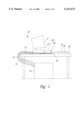
- FIG. 1 is a side view of a computer having a keyboard and two input devices in accordance with an embodiment of the invention.
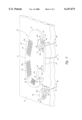
- FIG. 2 is a top rear isometric view of the keyboard shown in FIG. 1.
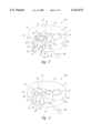
- FIG. 3 is a detailed top isometric view of one of the input devices shown in FIG. 2.
- FIG. 4 is a top isometric view of an input device having input buttons in accordance with another embodiment of the invention.
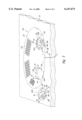
- FIG. 5 is a top rear isometric view of a keyboard and input devices in accordance with still another embodiment of the invention.
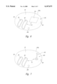
- FIG. 6 is a top isometric view of an input device having a pointing device in accordance with yet another embodiment of the invention.
- FIG. 7 is a top isometric view of an input device having a pointing device in accordance with yet another embodiment of the invention.
- the present invention is directed toward input devices and keyboards for personal computers.
- an input device may be attached to or detached from the keyboard, and the input device may have input buttons configured to engage a user's fingers in an ergonomic position.
- FIGS. 1-7 Many specific details of certain embodiments of the invention are set forth in the following description and in FIGS. 1-7 to provide a thorough understanding of such embodiments.
- FIG. 1 is a side view of a computer 20 having a display 21 coupled to a base 22.
- the base 22 is positioned on a flat work surface 23, such as a desktop, and is coupled to a processor 24 by a cable 25.
- a first input device such as a keyboard 30, is positioned on the work surface 23 adjacent the base 22, and the first input device is also coupled to the processor 24 by another cable 25.
- the keyboard 30 includes a plurality of input keys 36 and a pair of second input devices 50 (only one shown in FIG. 1).
- the second input devices 50 are each coupled to the processor 24 by a communication link 80.
- a user (not shown) transmits signals to the processor 24 via the communication link 80 and the cables 25 by manipulating the second input devices 50 and the input keys 36.
- FIG. 2 is a top rear isometric view of an embodiment of the keyboard 30 in accordance with the invention.
- the keyboard 30 includes a keyboard housing 41 having an upwardly facing top surface 31 and a downwardly facing bottom surface 32 opposite the top surface.
- a forward surface 33 facing toward the user and a rear surface 34 facing away from the user both extend between the top and bottom surfaces 31 and 32.
- the top surface 31 may have a curved outer edge 43, and in one embodiment, both the top surface 31 and bottom surface 32 have a generally oval shape to orient the input keys 36 and the second input devices 50 in ergonomic positions. In other embodiments, the top and bottom surfaces 31 and 32 may have other shapes that similarly orient the input keys 36 and the second input devices 50 in positions that are comfortable for the user.
- the top surface 31 includes a plurality of input key apertures 35 (shown by reference numbers 35a, 35b and 35c) from which the input keys 36 project.
- the input key apertures 35a and 35b may each accommodate approximately half a standard QWERTY input key configuration and may be canted toward each other to orient the user's hands in an ergonomic position.
- the input key aperture 35c may be shaped to accommodate additional input keys 36, such as number keys, function keys or other types of input keys.
- the top surface 31 further includes two device openings or bays 37 (shown by reference numbers 37a and 37b) positioned toward opposite ends of the keyboard 30. Each opening 37 is configured to removably receive one of the second input devices 50 (indicated by reference numbers 50a and 50b). Accordingly, the top surface 31 may include a right opening 37a to receive one second input device 50a and a left opening 37b to receive the other second input device 50b. Each of the second input devices 50 may be moved into and out of an opening 37 between an attached position and a detached position. For purposes of illustration, the second input device 50a is shown in the detached position, and the second input device 50b is shown in the attached position. As will be discussed in greater detail below, the second input devices 50 may be operated by the user when in either the attached or the detached positions.
- FIG. 3 is a detailed top isometric view of the second input device 50a shown in FIG. 2.
- the components and features of one second input device 50a may be similar to those of the other second input device 50b, and thus, unless otherwise noted, the description and reference numbers of the second input device 50a apply generally to the second input device 50b.
- the second input device 50a has a device housing 51 (FIG. 3) with an upper surface 53 (FIG. 3), a lower surface 54 (FIG. 3), and an outer surface 60 extending between the upper and lower surfaces 53 and 54.
- the outer surface 60 has a front portion 55 (FIG. 3) facing toward the user and a rear portion 56 facing away from the user when the user operates the second input device 50a.
- the upper surface 53 may include a convex region 62 between the front and rear portions 55 and 56 to support the palm of a user's hand.
- a plurality of controls 61 may be positioned at least partially rearward of the convex region 62 at the rear portion 56 of the housing 51. Signals generated by the controls 61 are transmitted to the processor 24 (FIG. 1) via the communication link 80, which may include a cable 81 extending from the rear portion 56.
- the controls 61 may include a pointing device 70 to move images on the display 21 (FIG. 1) and two input buttons 90 to transmit command signals to the processor 24 (FIG. 1).
- the pointing device 70 may include a roller ball 71 projecting upwardly from the upper surface 53. The roller ball 71 may be rotated relative to the housing 51 to move a pointing icon across the display 21.
- other pointing devices may be used in the second input devices 50 in other embodiments.
- the input buttons 90 may be positioned within the device housing 51 in two button apertures 52.
- the button apertures 52 and the input buttons 90 may have an elongated dimension extending along finger axes A 1 --A 1 and A 2 --A 2 .
- each input button 90 may have a top surface 98 extending along one of the finger axes A 1 --A 1 or A 2 --A 2 to engage and support a substantial portion of a user's finger in operation.
- the top surface 98 of each input button 90 more specifically, may have a proximal section 92 extending along one of the finger axes and a distal section 99 curving downwardly from the corresponding finger axis toward the lower surface 54 of the housing 51.
- the proximal section 92 may have a length between approximately 1.25" and approximately 5.0", and the distal section 99 may have a length between approximately 0.5" and 2.0".
- the curve between the proximal section 92 and the distal section 99 may be proximate to the back portion 56 of the housing 51.
- the top surface 98 of each button 90 is accordingly shaped to conform to a finger of the user when the distal phalange of the finger (i.e., the portion of the finger located between the last knuckle and the finger tip) is bent or curled slightly downwardly.
- the user's fingers may bend over the input buttons 90 in an ergonomic position such that the distal phalanges are engaged by the distal section 99 and the intermediate and/or the proximal phalanges (located progressively closer to the user's hand) are engaged by the proximal section 92.
- the button apertures 52 may extend through both the upper surface 53 and the back portion 56 of the housing 51. Additionally, the distal sections 99 of the input buttons 90 are accessible through the opening 37 in the keyboard housing 31 (FIG. 2) when the second input device 50 is attached to the keyboard 30 (FIG. 2).
- the top surface 98 of the input buttons 90 may also be contoured to engage more surface area of the user's finger.
- the top surface 98 is generally concave relative to the upper surface 53 and the back portion 56 of the housing 51.
- each top surface 98 may also have a rounded lower portion 95 to support the lower surface of the user's finger, and each top surface 98 may have side portions 93 to engage the side surfaces of the user's finger.
- the overall width of the top surface 98 may be between approximately 0.375" and approximately 1.5".
- the edges of the side portions 93 may be flush with the upper surface 53 of the housing 51 (shown in FIG. 3), or they may project slightly above or below the upper surface 53.
- an end portion 96 of each distal section 99 may be rounded.
- the input buttons 90 are movable relative to the device housing 51 along a motion path indicated by arrow 97 between a raised position (shown in FIG. 3) and a depressed position (not shown).
- the user vertically depresses the input buttons 90 in a conventional manner by pivoting the proximal and/or intermediate phalange of the user's finger relative to the user's hand.
- the input buttons 90 are movable horizontally as indicated by arrow 97a between an extended position (shown in FIG. 3) and a retracted position (not shown) by pivoting the distal and/or the intermediate phalanges of the user's fingers.
- users may rest their index fingers on one of the input buttons 90 and one of their middle fingers on the other input button to selectively activate either button.
- the input buttons 90 may be activated with other digits as well.
- the controls 61 of the second input device 50a are arranged so that right-handed users may engage one input button 90 with their index finger, the other input button 90 with one of their middle fingers, and the pointing device 70 with their thumb.
- the arrangement of the input buttons 90 and the pointing device 70 of the second input device 50b generally mirror the arrangement of the second input device 50a, except that the controls 61 of the second input device 50b are operated by the left hand of a user.
- the second input devices 50 may be attached to or detached from the keyboard 30 to be operated in either position.
- the second input device 50 may be pulled upward and out of the opening 37 (FIG. 2).
- the second input device 50 may be inserted downward into the opening 37.
- the second input device 50 may be slid horizontally into the device opening 37.
- the outer surface 60 of second input device 50 may be flush with the curved outer edge 43 of the keyboard 30 to define a smooth contour along the backside of the keyboard 30.
- the second input devices 50 may also be prevented from passing through the bottom surface 32 of the keyboard 30.
- a plurality of tabs 38 may project inwardly into each device opening 37 from the bottom surface 32 of the keyboard 30 to prevent the corresponding second input devices 50 from passing entirely through the device opening 37.
- the outer surface 60 of the second input device 50 and an inner surface 46 of the opening 37 may be tapered inwardly so that the second input device 50 wedges against the inner surface 46 when it is attached to the keyboard 30.
- the second input device 50 may also be releasably secured to the keyboard 30 with latching device 44.
- the latching device 44 includes a pair of first engagement members 42 that may be aligned with corresponding second engagement members 58 in the outer surface 60 of the second input device 50.
- the first engagement members 42 may be spring-loaded balls biased inwardly toward the center of the device opening 37, and the second engagement members 58 may be sockets in the second input device 50 that receive the balls 42 when the second input device is placed within the opening 37.
- the latching device 44 may have a tab (not shown) that snaps into a detent (not shown) or other mechanisms that releasably secure the second input devices 50 to the keyboard 30.
- the second input devices 50 and the keyboard 30 shown in FIGS. 1-3 may be more comfortable and less fatiguing to use than conventional input devices and keyboards.
- the input buttons 90 have an elongated proximal section 92 and a distal section 99 curved downward from the proximal section 92, each input button supports a substantial portion of a user's finger even when the finger is flexed at the knuckles in an ergonomic position. Accordingly, users may bend their fingers over the input buttons 90 in a relaxed position, potentially reducing the likelihood for fatigue and/or repetitive stress disorders.
- the second input devices 50 and the keyboard 30 may also be easier to use compared to conventional devices because the input buttons 90 may have concave top surfaces 98 to engage both the lower and side surfaces of the user's fingers.
- the concave shape of the top surfaces may potentially reduce the likelihood of inadvertently depressing the incorrect input button because they make it easier to feel the location of the buttons.
- the second input devices 50 may be easier to use.
- the second input device 50 and the keyboard 30 shown in FIGS. 1-3 also enhance the convenience and flexibility to operating the computer.
- the keyboard 30 includes two second input devices 50a and 50b that are configured to be engaged by the user's right hand and left hand, respectively. Accordingly, users may operate either the right input device 50a or the left input device 50b, depending on their preference. Furthermore, unlike conventional keyboards and input devices, multiple users with different preferences may operate the same keyboard 30 without having to replace one input device with another that more closely accommodates an individual user's dexterity.
- the second input device 50 and the keyboard 30 shown in FIGS. 1-3 may also enhance the versatility and convenience of the computer 20 because the second input devices 50 are accessible to the user in either the detached or attached positions. For example, in particularly cramped or confined situations, the second input device 50 may be operated in the attached position. Conversely, in less confined environments, the user may detach the second input device 50 and operate it apart from the keyboard 30.
- FIG. 4 is a top isometric view of another second input device 150a having input buttons 190 in accordance with another embodiment of the invention.
- each input button 190 is canted about a corresponding finger axis A 1 --A 1 or A 2 --A 2 from the vertical, as indicated by angle ⁇ , so that a distal section 199 of each input button 190 is inclined toward the pointing device 70.
- the button apertures 52 are shaped to accommodate the canted input buttons 190.
- the motion path 197 along which each input button 190 travels as it is activated is also canted so as to form an acute angle ⁇ with the housing upper surface 53.
- An advantage of the canted input buttons 190 shown in FIG. 4 is that users may rotate their wrists slightly outward when operating the input buttons 190. This orientation may be more comfortable and produce less strain in the tendons of the user's hands and fingers.
- FIG. 5 is a top isometric view of another keyboard 230 with two second input devices 250 (shown by reference numbers 250a and 250b) having rounded outer surfaces 260 and smoothly contoured upper surfaces 253 in accordance with another embodiment of the invention. Accordingly, a top surface 231 of the keyboard 230 may be smoothly contoured with both the rear surface 234 and the forward surface 233 to form a rounded outer edge 243.
- Two openings 237 (shown by reference numbers 237a and 237b) in the keyboard 230 are open to both the top surface 231 and the rear surface 234 to receive the second input devices 250.
- the outer surfaces 260 and the top surfaces 253 of the input devices 250 may be generally flush with the outer edge 243 and the top surface 231 of the keyboard 230 when the input devices 250 are positioned in the device openings 237.
- each opening 237 has an open end 239 in the top surface 231 and a closed end 240 in the bottom surface 232. Accordingly, the second input device 250 rests on the closed end 240 in the attached position so as not to pass completely through the device opening 237.
- each second input device 250 may include a pair of sockets 58 to receive spring-loaded balls 42 positioned in the inner surface 46 of the device opening 237 to secure the second input device 250 to the keyboard 230.
- the top surface 231 of the keyboard 230 may include a finger slot 245 at each opening 237 to more easily detach the second input devices 250 from the keyboard 230.
- Each second input device 250 may be operatively coupled to the computer 20 (FIG. 1) by a wireless communication link 280 having a transmitter 282 in the second input device 250 and a receiver 283 in the base 22 (FIG. 1).
- the controls 61 send command signals to the transmitter 282, which broadcasts the signals at a selected frequency to the receiver 283.
- the transmitter 282 and receiver 283 operate with infrared signals, and in another embodiment the transmitter 282 and receiver 283 operate at radio frequencies.
- the transmitter 282 may be positioned in the back portion 256 of the second input device 250 to be aligned with the receiver 283 when the second input device 250 is either attached to or detached from the keyboard 230.
- the curved second input device 250 and the curved keyboard 230 shown in FIG. 5 may be more comfortably gripped than a conventional square edged keyboard and input device. Additionally, the wireless communication link 280 allows the second input device 250 to be moved to a variety of positions to allow more convenient operation of the second input device 250.
- Still another advantage of the keyboard 230 is that the closed end 240 of the opening 237 may more completely support the second input device 250 when the second input device is in the attached position.
- the closed end 240 may also prevent the second input device from being inadvertently bumped upwardly out of the opening 237 from below.
- an advantage of the device opening 37 shown in FIG. 2 is that it may allow the input device to be more easily removed from the opening because the device opening 37 is open to the bottom surface 32 of the keyboard.
- the second input device may include several other pointing mechanisms.
- the pointing device 370 may be a touch-sensitive pad 373 to move images on the display 21 (FIG. 1) corresponding to the motion of the user's fingers on the surface of the touch pad 373.
- the pointing device 470 may be a joystick 472 that pivots with respect to the housing 51.
- An advantage of the touch pad 373 and joystick 472 is that either one may be preferred by certain users over the roller ball 71 shown in FIGS. 1-5.
- the second input devices shown in the figures may include more than two input buttons and/or more than one pointing device. Accordingly, the invention is not limited except as by the appended claims.
Abstract
Description
Claims (66)
Priority Applications (1)
| Application Number | Priority Date | Filing Date | Title |
|---|---|---|---|
| US09/044,387 US6147673A (en) | 1998-03-18 | 1998-03-18 | Computer input device and keyboard |
Applications Claiming Priority (1)
| Application Number | Priority Date | Filing Date | Title |
|---|---|---|---|
| US09/044,387 US6147673A (en) | 1998-03-18 | 1998-03-18 | Computer input device and keyboard |
Publications (1)
| Publication Number | Publication Date |
|---|---|
| US6147673A true US6147673A (en) | 2000-11-14 |
Family
ID=21932113
Family Applications (1)
| Application Number | Title | Priority Date | Filing Date |
|---|---|---|---|
| US09/044,387 Expired - Lifetime US6147673A (en) | 1998-03-18 | 1998-03-18 | Computer input device and keyboard |
Country Status (1)
| Country | Link |
|---|---|
| US (1) | US6147673A (en) |
Cited By (17)
| Publication number | Priority date | Publication date | Assignee | Title |
|---|---|---|---|---|
| US6549191B2 (en) | 1998-06-25 | 2003-04-15 | Micron Technology, Inc. | Method for operating an ergonomic keyboard |
| US6580421B1 (en) * | 1998-06-25 | 2003-06-17 | Micron Technology, Inc. | Ergonomic keyboard |
| US6581931B1 (en) | 2002-01-29 | 2003-06-24 | Connector Set Limited Partnership | Game board structure for construction toy set |
| US6609977B1 (en) | 2000-08-23 | 2003-08-26 | Nintendo Co., Ltd. | External interfaces for a 3D graphics system |
| US6690352B2 (en) * | 2001-03-08 | 2004-02-10 | Primax Electronics Ltd. | Multi-mode input control device |
| US6712534B2 (en) | 2001-07-23 | 2004-03-30 | Sanjay M. Patel | Ergonomic and efficient keyboard |
| US6757159B2 (en) | 1998-03-18 | 2004-06-29 | Micron Technology, Inc. | Laptop computer base |
| US20040204241A1 (en) * | 2001-10-03 | 2004-10-14 | Houston Lori A. | Virtual vegas video keyboard |
| US20070216651A1 (en) * | 2004-03-23 | 2007-09-20 | Sanjay Patel | Human-to-Computer Interfaces |
| US20080266263A1 (en) * | 2005-03-23 | 2008-10-30 | Keypoint Technologies (Uk) Limited | Human-To-Mobile Interfaces |
| US20080284731A1 (en) * | 2005-10-21 | 2008-11-20 | Vtech Electronics North America, Llc | Reconfigurable User Input Device For Both Left and Right Handed Users |
| US20110024497A1 (en) * | 2009-08-03 | 2011-02-03 | Toshiba Tec Kabushiki Kaisha | Card processing apparatus |
| US7976392B2 (en) | 2000-08-23 | 2011-07-12 | Nintendo Co., Ltd. | External interfaces for a 3D graphics system |
| US20110306423A1 (en) * | 2010-06-10 | 2011-12-15 | Isaac Calderon | Multi purpose wireless game control console |
| US9798717B2 (en) | 2005-03-23 | 2017-10-24 | Keypoint Technologies (Uk) Limited | Human-to-mobile interfaces |
| US20170354872A1 (en) * | 2016-06-10 | 2017-12-14 | Nintendo Co., Ltd. | Game controller |
| US10441878B2 (en) | 2016-06-10 | 2019-10-15 | Nintendo Co., Ltd. | Game controller |
Citations (46)
| Publication number | Priority date | Publication date | Assignee | Title |
|---|---|---|---|---|
| US2783109A (en) * | 1955-01-03 | 1957-02-26 | Frey Ephriam | Lap tray with leg-engaging means |
| US3859930A (en) * | 1972-03-28 | 1975-01-14 | Peter G Sherwin | Tiltable tray with pivotally mounted legs having extensible feet |
| US4052944A (en) * | 1975-11-20 | 1977-10-11 | Jennings Russell A | Portable shuffle desk |
| US4765583A (en) * | 1987-08-25 | 1988-08-23 | Tenner Wanda C | Lap desk |
| US4852498A (en) * | 1989-03-20 | 1989-08-01 | Curtis Manufacturing Company, Inc. | Lap top computer work station |
| CH674693A5 (en) * | 1988-01-26 | 1990-07-13 | Gafner Maschinenbau Ag | Manure spreader with transverse rotor - has deflecting stator, partly surrounding rotor, with peripheral adjustment, extending spreading angle |
| US5021771A (en) * | 1988-08-09 | 1991-06-04 | Lachman Ronald D | Computer input device with two cursor positioning spheres |
| US5029260A (en) * | 1990-03-19 | 1991-07-02 | The Board Of Supervisors Of Louisiana State University | Keyboard having convex curved surface |
| US5049863A (en) * | 1989-02-10 | 1991-09-17 | Kabushiki Kaisha Toshiba | Cursor key unit for a computer having a mouse function removably mounted on a keyboard section of a base |
| US5054736A (en) * | 1990-06-01 | 1991-10-08 | Bruno Champoux | Laptop reading and writing stand |
| GB2244546A (en) * | 1990-05-10 | 1991-12-04 | Primax Electronics Ltd | Computer input device |
| US5073050A (en) * | 1990-06-12 | 1991-12-17 | Steffen Andrews | Ergonomic keyboard apparatus |
| US5081936A (en) * | 1989-11-22 | 1992-01-21 | Drieling Gerald L | Compressible desk arrangements |
| US5187644A (en) * | 1991-11-14 | 1993-02-16 | Compaq Computer Corporation | Compact portable computer having an expandable full size keyboard with extendable supports |
| US5263423A (en) * | 1992-02-07 | 1993-11-23 | Rolf Anderson | Article securement device |
| US5281958A (en) * | 1989-10-23 | 1994-01-25 | Microsoft Corporation | Pointing device with adjustable clamp attachable to a keyboard |
| US5355811A (en) * | 1993-03-31 | 1994-10-18 | Brewer Brian H | Adjustable leg supported mouse pad |
| US5397189A (en) * | 1993-04-29 | 1995-03-14 | Minogue; Richard F. | Non-planar ergonomic keyboard |
| US5416498A (en) * | 1986-10-21 | 1995-05-16 | Ergonomics, Inc. | Prehensile positioning computer keyboard |
| US5416730A (en) * | 1993-11-19 | 1995-05-16 | Appcon Technologies, Inc. | Arm mounted computer |
| US5423227A (en) * | 1991-10-30 | 1995-06-13 | U.S. Philips Corporation | Device for generating multi-directional commands |
| US5428355A (en) * | 1992-03-23 | 1995-06-27 | Hewlett-Packard Corporation | Position encoder system |
| US5466078A (en) * | 1989-07-07 | 1995-11-14 | Health Care Keyboard Company | Input keyboard apparatus for information processing and other keyboard devices |
| US5502460A (en) * | 1993-05-26 | 1996-03-26 | Bowen; James H. | Ergonomic laptop computer and ergonomic keyboard |
| US5504500A (en) * | 1989-10-23 | 1996-04-02 | Microsoft Corporation | User programmable orientation of cursor movement direction |
| US5519569A (en) * | 1994-06-30 | 1996-05-21 | Compaq Computer Corporation | Compact notebook computer having a foldable and collapsible keyboard structure |
| US5527116A (en) * | 1993-11-12 | 1996-06-18 | Maxi Switch, Inc. | Adjustable keyboard |
| US5541593A (en) * | 1992-07-02 | 1996-07-30 | Arsem; A. Donald | Computer keyboard |
| US5564844A (en) * | 1994-12-06 | 1996-10-15 | Patterson, Jr.; John L. | Automatic keyboard moving apparatus |
| US5583744A (en) * | 1994-09-06 | 1996-12-10 | Citizen Watch Co., Ltd. | Portable computer with detachable battery pack |
| US5644338A (en) * | 1993-05-26 | 1997-07-01 | Bowen; James H. | Ergonomic laptop computer and ergonomic keyboard |
| US5645277A (en) * | 1994-11-15 | 1997-07-08 | Top Game & Company Ltd. | Controller for a video game console |
| US5648772A (en) * | 1995-01-11 | 1997-07-15 | Deckel Maho Gmbh | Control console for a program-controlled machine tool |
| US5659307A (en) * | 1994-03-23 | 1997-08-19 | International Business Machines Corporation | Keyboard with biased movable keyboard sections |
| US5662422A (en) * | 1991-09-05 | 1997-09-02 | Fort; Chris | Bifurcated keyboard arrangement |
| US5692815A (en) * | 1996-04-24 | 1997-12-02 | Murphy; Kevin M. | Computer mouse pad and item holder |
| US5726683A (en) * | 1995-08-09 | 1998-03-10 | Midas Mouse International Pty. | Ergonomic computer mouse |
| US5732910A (en) * | 1995-10-02 | 1998-03-31 | Martin; Mary L. | Computer support apparatus |
| US5743666A (en) * | 1997-02-25 | 1998-04-28 | Datahand Systems, Inc. | Adjustable keyboard |
| US5818690A (en) * | 1997-04-30 | 1998-10-06 | Gateway 2000, Inc. | Lap top computer system with front elevating feet |
| US5825612A (en) * | 1997-03-31 | 1998-10-20 | Compaq Computer Corporation | Lap-supportable remote infrared computer keyboard |
| US5862933A (en) * | 1997-10-06 | 1999-01-26 | Neville; Boyd A. | Portable lap tray |
| US5871094A (en) * | 1998-01-22 | 1999-02-16 | Leibowitz; Marc | Laptop computer case and stand |
| US5886686A (en) * | 1996-10-21 | 1999-03-23 | Chen; Frank | Keyboard with replaceable cursor control means |
| US5893540A (en) * | 1997-09-04 | 1999-04-13 | Webtv Networks, Inc. | Keyboard saddle |
| US5957595A (en) * | 1997-12-30 | 1999-09-28 | Chen; Kuo-An | Multimedia keyboard device having game rods on each end |
-
1998
- 1998-03-18 US US09/044,387 patent/US6147673A/en not_active Expired - Lifetime
Patent Citations (46)
| Publication number | Priority date | Publication date | Assignee | Title |
|---|---|---|---|---|
| US2783109A (en) * | 1955-01-03 | 1957-02-26 | Frey Ephriam | Lap tray with leg-engaging means |
| US3859930A (en) * | 1972-03-28 | 1975-01-14 | Peter G Sherwin | Tiltable tray with pivotally mounted legs having extensible feet |
| US4052944A (en) * | 1975-11-20 | 1977-10-11 | Jennings Russell A | Portable shuffle desk |
| US5416498A (en) * | 1986-10-21 | 1995-05-16 | Ergonomics, Inc. | Prehensile positioning computer keyboard |
| US4765583A (en) * | 1987-08-25 | 1988-08-23 | Tenner Wanda C | Lap desk |
| CH674693A5 (en) * | 1988-01-26 | 1990-07-13 | Gafner Maschinenbau Ag | Manure spreader with transverse rotor - has deflecting stator, partly surrounding rotor, with peripheral adjustment, extending spreading angle |
| US5021771A (en) * | 1988-08-09 | 1991-06-04 | Lachman Ronald D | Computer input device with two cursor positioning spheres |
| US5049863A (en) * | 1989-02-10 | 1991-09-17 | Kabushiki Kaisha Toshiba | Cursor key unit for a computer having a mouse function removably mounted on a keyboard section of a base |
| US4852498A (en) * | 1989-03-20 | 1989-08-01 | Curtis Manufacturing Company, Inc. | Lap top computer work station |
| US5466078A (en) * | 1989-07-07 | 1995-11-14 | Health Care Keyboard Company | Input keyboard apparatus for information processing and other keyboard devices |
| US5504500A (en) * | 1989-10-23 | 1996-04-02 | Microsoft Corporation | User programmable orientation of cursor movement direction |
| US5281958A (en) * | 1989-10-23 | 1994-01-25 | Microsoft Corporation | Pointing device with adjustable clamp attachable to a keyboard |
| US5081936A (en) * | 1989-11-22 | 1992-01-21 | Drieling Gerald L | Compressible desk arrangements |
| US5029260A (en) * | 1990-03-19 | 1991-07-02 | The Board Of Supervisors Of Louisiana State University | Keyboard having convex curved surface |
| GB2244546A (en) * | 1990-05-10 | 1991-12-04 | Primax Electronics Ltd | Computer input device |
| US5054736A (en) * | 1990-06-01 | 1991-10-08 | Bruno Champoux | Laptop reading and writing stand |
| US5073050A (en) * | 1990-06-12 | 1991-12-17 | Steffen Andrews | Ergonomic keyboard apparatus |
| US5662422A (en) * | 1991-09-05 | 1997-09-02 | Fort; Chris | Bifurcated keyboard arrangement |
| US5423227A (en) * | 1991-10-30 | 1995-06-13 | U.S. Philips Corporation | Device for generating multi-directional commands |
| US5187644A (en) * | 1991-11-14 | 1993-02-16 | Compaq Computer Corporation | Compact portable computer having an expandable full size keyboard with extendable supports |
| US5263423A (en) * | 1992-02-07 | 1993-11-23 | Rolf Anderson | Article securement device |
| US5428355A (en) * | 1992-03-23 | 1995-06-27 | Hewlett-Packard Corporation | Position encoder system |
| US5541593A (en) * | 1992-07-02 | 1996-07-30 | Arsem; A. Donald | Computer keyboard |
| US5355811A (en) * | 1993-03-31 | 1994-10-18 | Brewer Brian H | Adjustable leg supported mouse pad |
| US5397189A (en) * | 1993-04-29 | 1995-03-14 | Minogue; Richard F. | Non-planar ergonomic keyboard |
| US5502460A (en) * | 1993-05-26 | 1996-03-26 | Bowen; James H. | Ergonomic laptop computer and ergonomic keyboard |
| US5644338A (en) * | 1993-05-26 | 1997-07-01 | Bowen; James H. | Ergonomic laptop computer and ergonomic keyboard |
| US5527116A (en) * | 1993-11-12 | 1996-06-18 | Maxi Switch, Inc. | Adjustable keyboard |
| US5416730A (en) * | 1993-11-19 | 1995-05-16 | Appcon Technologies, Inc. | Arm mounted computer |
| US5659307A (en) * | 1994-03-23 | 1997-08-19 | International Business Machines Corporation | Keyboard with biased movable keyboard sections |
| US5519569A (en) * | 1994-06-30 | 1996-05-21 | Compaq Computer Corporation | Compact notebook computer having a foldable and collapsible keyboard structure |
| US5583744A (en) * | 1994-09-06 | 1996-12-10 | Citizen Watch Co., Ltd. | Portable computer with detachable battery pack |
| US5645277A (en) * | 1994-11-15 | 1997-07-08 | Top Game & Company Ltd. | Controller for a video game console |
| US5564844A (en) * | 1994-12-06 | 1996-10-15 | Patterson, Jr.; John L. | Automatic keyboard moving apparatus |
| US5648772A (en) * | 1995-01-11 | 1997-07-15 | Deckel Maho Gmbh | Control console for a program-controlled machine tool |
| US5726683A (en) * | 1995-08-09 | 1998-03-10 | Midas Mouse International Pty. | Ergonomic computer mouse |
| US5732910A (en) * | 1995-10-02 | 1998-03-31 | Martin; Mary L. | Computer support apparatus |
| US5692815A (en) * | 1996-04-24 | 1997-12-02 | Murphy; Kevin M. | Computer mouse pad and item holder |
| US5886686A (en) * | 1996-10-21 | 1999-03-23 | Chen; Frank | Keyboard with replaceable cursor control means |
| US5743666A (en) * | 1997-02-25 | 1998-04-28 | Datahand Systems, Inc. | Adjustable keyboard |
| US5825612A (en) * | 1997-03-31 | 1998-10-20 | Compaq Computer Corporation | Lap-supportable remote infrared computer keyboard |
| US5818690A (en) * | 1997-04-30 | 1998-10-06 | Gateway 2000, Inc. | Lap top computer system with front elevating feet |
| US5893540A (en) * | 1997-09-04 | 1999-04-13 | Webtv Networks, Inc. | Keyboard saddle |
| US5862933A (en) * | 1997-10-06 | 1999-01-26 | Neville; Boyd A. | Portable lap tray |
| US5957595A (en) * | 1997-12-30 | 1999-09-28 | Chen; Kuo-An | Multimedia keyboard device having game rods on each end |
| US5871094A (en) * | 1998-01-22 | 1999-02-16 | Leibowitz; Marc | Laptop computer case and stand |
Non-Patent Citations (7)
| Title |
|---|
| RCA Remote Model No. RTB100, Bottom Isometric View. * |
| RCA Remote Model No. RTB100, Top Isometric View. * |
| Sejin Electron Inc., SWK 5697WT, Bottom Isometric View. * |
| Sejin Electron inc., SWK 5697WT, Top Isometric View. * |
| Sejin Electron Inc., SWK-5697WT, Bottom Isometric View. |
| Sejin Electron inc., SWK-5697WT, Top Isometric View. |
| Sony Playstation, Top Isometric View. * |
Cited By (24)
| Publication number | Priority date | Publication date | Assignee | Title |
|---|---|---|---|---|
| US6757159B2 (en) | 1998-03-18 | 2004-06-29 | Micron Technology, Inc. | Laptop computer base |
| US20040228084A1 (en) * | 1998-03-18 | 2004-11-18 | Lynne Zarek | Laptop computer base |
| US6894894B2 (en) | 1998-03-18 | 2005-05-17 | Micron Technology, Inc. | Laptop computer base |
| US6580421B1 (en) * | 1998-06-25 | 2003-06-17 | Micron Technology, Inc. | Ergonomic keyboard |
| US6549191B2 (en) | 1998-06-25 | 2003-04-15 | Micron Technology, Inc. | Method for operating an ergonomic keyboard |
| US7976392B2 (en) | 2000-08-23 | 2011-07-12 | Nintendo Co., Ltd. | External interfaces for a 3D graphics system |
| US6609977B1 (en) | 2000-08-23 | 2003-08-26 | Nintendo Co., Ltd. | External interfaces for a 3D graphics system |
| US6690352B2 (en) * | 2001-03-08 | 2004-02-10 | Primax Electronics Ltd. | Multi-mode input control device |
| US6712534B2 (en) | 2001-07-23 | 2004-03-30 | Sanjay M. Patel | Ergonomic and efficient keyboard |
| US20040204241A1 (en) * | 2001-10-03 | 2004-10-14 | Houston Lori A. | Virtual vegas video keyboard |
| US6581931B1 (en) | 2002-01-29 | 2003-06-24 | Connector Set Limited Partnership | Game board structure for construction toy set |
| US9678580B2 (en) | 2004-03-23 | 2017-06-13 | Keypoint Technologies (UK) Limted | Human-to-computer interfaces |
| US20070216651A1 (en) * | 2004-03-23 | 2007-09-20 | Sanjay Patel | Human-to-Computer Interfaces |
| US20080266263A1 (en) * | 2005-03-23 | 2008-10-30 | Keypoint Technologies (Uk) Limited | Human-To-Mobile Interfaces |
| US9798717B2 (en) | 2005-03-23 | 2017-10-24 | Keypoint Technologies (Uk) Limited | Human-to-mobile interfaces |
| US10365727B2 (en) | 2005-03-23 | 2019-07-30 | Keypoint Technologies (Uk) Limited | Human-to-mobile interfaces |
| US20080284731A1 (en) * | 2005-10-21 | 2008-11-20 | Vtech Electronics North America, Llc | Reconfigurable User Input Device For Both Left and Right Handed Users |
| US8493325B2 (en) * | 2005-10-21 | 2013-07-23 | Stephine Mak Pui See | Reconfigurable user input device for both left and right handed users |
| US20110024497A1 (en) * | 2009-08-03 | 2011-02-03 | Toshiba Tec Kabushiki Kaisha | Card processing apparatus |
| US8632004B2 (en) * | 2009-08-03 | 2014-01-21 | Toshiba Tec Kabushiki Kaisha | Card processing apparatus |
| US20110306423A1 (en) * | 2010-06-10 | 2011-12-15 | Isaac Calderon | Multi purpose wireless game control console |
| US20170354872A1 (en) * | 2016-06-10 | 2017-12-14 | Nintendo Co., Ltd. | Game controller |
| US10441878B2 (en) | 2016-06-10 | 2019-10-15 | Nintendo Co., Ltd. | Game controller |
| US11224800B2 (en) * | 2016-06-10 | 2022-01-18 | Nintendo Co., Ltd. | Game controller |
Similar Documents
| Publication | Publication Date | Title |
|---|---|---|
| US6147673A (en) | Computer input device and keyboard | |
| US7277083B2 (en) | Ergonomically designed computer gaming device | |
| US6549191B2 (en) | Method for operating an ergonomic keyboard | |
| US5719743A (en) | Torso worn computer which can stand alone | |
| US6545667B1 (en) | Apparatus for a convenient and comfortable cursor control device | |
| US5433407A (en) | Palm rest for use with computer pointing devices | |
| US5831819A (en) | Hand-held data collection terminal with a contoured protrusion | |
| US7701443B2 (en) | Ergonomic computer mouse | |
| US6850224B2 (en) | Wearable ergonomic computer mouse | |
| US6088022A (en) | Spherical keyboard with built-in mouse | |
| KR0133549B1 (en) | Laptop computer with pomlest and keyboard and cursor | |
| US20020175894A1 (en) | Hand-supported mouse for computer input | |
| US20020140676A1 (en) | Key free mouse | |
| US9063587B2 (en) | Computer input device with ergonomically formed and positioned actuators | |
| US5990870A (en) | Finger rest structure of computer mouse | |
| US20050052291A1 (en) | Portable data input device and use of such a device | |
| GB2318764A (en) | Ergonomic computer keyboard | |
| US6847352B2 (en) | Stress relieving mouse | |
| US6549189B1 (en) | Method for operating a computer input device and keyboard | |
| US6954198B2 (en) | Ergonomically shaped computer pointing device | |
| US6580421B1 (en) | Ergonomic keyboard | |
| EA002610B1 (en) | Thumb-actuated computer-input device | |
| US20070285400A1 (en) | Palm attached touch-pad computer mouse | |
| US20230205327A1 (en) | Adjustable supporting assembly for user of ergonomic mouse, and ergonomic adjustable computer mouse | |
| US6614421B1 (en) | Keyboard having buttons positioned for operation by heel of hand |
Legal Events
| Date | Code | Title | Description |
|---|---|---|---|
| AS | Assignment |
Owner name: MICRON ELECTRONICS, INC., IDAHO Free format text: ASSIGNMENT OF ASSIGNORS INTEREST;ASSIGNOR:ZAREK, LYNNE;REEL/FRAME:009073/0279 Effective date: 19980311 |
|
| STCF | Information on status: patent grant |
Free format text: PATENTED CASE |
|
| FEPP | Fee payment procedure |
Free format text: PAYOR NUMBER ASSIGNED (ORIGINAL EVENT CODE: ASPN); ENTITY STATUS OF PATENT OWNER: LARGE ENTITY |
|
| AS | Assignment |
Owner name: MEI CALIFORNIA, INC., CALIFORNIA Free format text: ASSIGNMENT OF ASSIGNORS INTEREST;ASSIGNOR:MICRON ELECTRONICS, INC.;REEL/FRAME:011658/0956 Effective date: 20010322 |
|
| FPAY | Fee payment |
Year of fee payment: 4 |
|
| FPAY | Fee payment |
Year of fee payment: 8 |
|
| FPAY | Fee payment |
Year of fee payment: 12 |
|
| AS | Assignment |
Owner name: U.S. BANK NATIONAL ASSOCIATION, AS COLLATERAL AGENT, CALIFORNIA Free format text: SECURITY INTEREST;ASSIGNOR:MICRON TECHNOLOGY, INC.;REEL/FRAME:038669/0001 Effective date: 20160426 Owner name: U.S. BANK NATIONAL ASSOCIATION, AS COLLATERAL AGEN Free format text: SECURITY INTEREST;ASSIGNOR:MICRON TECHNOLOGY, INC.;REEL/FRAME:038669/0001 Effective date: 20160426 |
|
| AS | Assignment |
Owner name: MORGAN STANLEY SENIOR FUNDING, INC., AS COLLATERAL AGENT, MARYLAND Free format text: PATENT SECURITY AGREEMENT;ASSIGNOR:MICRON TECHNOLOGY, INC.;REEL/FRAME:038954/0001 Effective date: 20160426 Owner name: MORGAN STANLEY SENIOR FUNDING, INC., AS COLLATERAL Free format text: PATENT SECURITY AGREEMENT;ASSIGNOR:MICRON TECHNOLOGY, INC.;REEL/FRAME:038954/0001 Effective date: 20160426 |
|
| AS | Assignment |
Owner name: U.S. BANK NATIONAL ASSOCIATION, AS COLLATERAL AGENT, CALIFORNIA Free format text: CORRECTIVE ASSIGNMENT TO CORRECT THE REPLACE ERRONEOUSLY FILED PATENT #7358718 WITH THE CORRECT PATENT #7358178 PREVIOUSLY RECORDED ON REEL 038669 FRAME 0001. ASSIGNOR(S) HEREBY CONFIRMS THE SECURITY INTEREST;ASSIGNOR:MICRON TECHNOLOGY, INC.;REEL/FRAME:043079/0001 Effective date: 20160426 Owner name: U.S. BANK NATIONAL ASSOCIATION, AS COLLATERAL AGEN Free format text: CORRECTIVE ASSIGNMENT TO CORRECT THE REPLACE ERRONEOUSLY FILED PATENT #7358718 WITH THE CORRECT PATENT #7358178 PREVIOUSLY RECORDED ON REEL 038669 FRAME 0001. ASSIGNOR(S) HEREBY CONFIRMS THE SECURITY INTEREST;ASSIGNOR:MICRON TECHNOLOGY, INC.;REEL/FRAME:043079/0001 Effective date: 20160426 |
|
| AS | Assignment |
Owner name: MICRON TECHNOLOGY, INC., IDAHO Free format text: RELEASE BY SECURED PARTY;ASSIGNOR:U.S. BANK NATIONAL ASSOCIATION, AS COLLATERAL AGENT;REEL/FRAME:047243/0001 Effective date: 20180629 |
|
| AS | Assignment |
Owner name: MICRON TECHNOLOGY, INC., IDAHO Free format text: RELEASE BY SECURED PARTY;ASSIGNOR:MORGAN STANLEY SENIOR FUNDING, INC., AS COLLATERAL AGENT;REEL/FRAME:050937/0001 Effective date: 20190731 |