US5259016A - Assembly for radiographic imaging - Google Patents
Assembly for radiographic imaging Download PDFInfo
- Publication number
- US5259016A US5259016A US07/965,147 US96514792A US5259016A US 5259016 A US5259016 A US 5259016A US 96514792 A US96514792 A US 96514792A US 5259016 A US5259016 A US 5259016A
- Authority
- US
- United States
- Prior art keywords
- emulsion layer
- layer unit
- imaging assembly
- screen
- apertures
- Prior art date
- Legal status (The legal status is an assumption and is not a legal conclusion. Google has not performed a legal analysis and makes no representation as to the accuracy of the status listed.)
- Expired - Lifetime
Links
- 238000003384 imaging method Methods 0.000 title claims abstract description 46
- 239000000839 emulsion Substances 0.000 claims abstract description 101
- -1 silver halide Chemical class 0.000 claims abstract description 47
- 229910052709 silver Inorganic materials 0.000 claims abstract description 27
- 239000004332 silver Substances 0.000 claims abstract description 27
- 239000000463 material Substances 0.000 claims abstract description 12
- 230000005540 biological transmission Effects 0.000 claims abstract description 9
- 238000012546 transfer Methods 0.000 claims abstract description 9
- OAICVXFJPJFONN-UHFFFAOYSA-N Phosphorus Chemical compound [P] OAICVXFJPJFONN-UHFFFAOYSA-N 0.000 claims description 31
- 229910052761 rare earth metal Inorganic materials 0.000 claims description 12
- 229910052771 Terbium Inorganic materials 0.000 claims description 10
- 230000005855 radiation Effects 0.000 claims description 10
- 229910052688 Gadolinium Inorganic materials 0.000 claims description 7
- 150000002910 rare earth metals Chemical class 0.000 claims description 7
- 229910052798 chalcogen Inorganic materials 0.000 claims description 6
- 150000001787 chalcogens Chemical class 0.000 claims description 6
- UIWYJDYFSGRHKR-UHFFFAOYSA-N gadolinium atom Chemical compound [Gd] UIWYJDYFSGRHKR-UHFFFAOYSA-N 0.000 claims description 6
- OYPRJOBELJOOCE-UHFFFAOYSA-N Calcium Chemical compound [Ca] OYPRJOBELJOOCE-UHFFFAOYSA-N 0.000 claims description 5
- 229910052775 Thulium Inorganic materials 0.000 claims description 5
- 239000011575 calcium Substances 0.000 claims description 5
- 229910052791 calcium Inorganic materials 0.000 claims description 5
- GZCRRIHWUXGPOV-UHFFFAOYSA-N terbium atom Chemical compound [Tb] GZCRRIHWUXGPOV-UHFFFAOYSA-N 0.000 claims description 5
- PBYZMCDFOULPGH-UHFFFAOYSA-N tungstate Chemical compound [O-][W]([O-])(=O)=O PBYZMCDFOULPGH-UHFFFAOYSA-N 0.000 claims description 5
- 229910052727 yttrium Inorganic materials 0.000 claims description 5
- VWQVUPCCIRVNHF-UHFFFAOYSA-N yttrium atom Chemical compound [Y] VWQVUPCCIRVNHF-UHFFFAOYSA-N 0.000 claims description 5
- 229910052765 Lutetium Inorganic materials 0.000 claims description 4
- 229910052769 Ytterbium Inorganic materials 0.000 claims description 4
- 229910052736 halogen Inorganic materials 0.000 claims description 4
- OHSVLFRHMCKCQY-UHFFFAOYSA-N lutetium atom Chemical compound [Lu] OHSVLFRHMCKCQY-UHFFFAOYSA-N 0.000 claims description 4
- 230000005670 electromagnetic radiation Effects 0.000 claims description 3
- 150000002367 halogens Chemical class 0.000 claims description 3
- BAZGIOYKWQZSCP-UHFFFAOYSA-N lutetium sulfur monoxide Chemical compound [Lu].O=S BAZGIOYKWQZSCP-UHFFFAOYSA-N 0.000 claims description 3
- 229910052751 metal Inorganic materials 0.000 claims description 3
- 239000002184 metal Substances 0.000 claims description 3
- 229910052758 niobium Inorganic materials 0.000 claims description 3
- 239000010955 niobium Substances 0.000 claims description 3
- GUCVJGMIXFAOAE-UHFFFAOYSA-N niobium atom Chemical compound [Nb] GUCVJGMIXFAOAE-UHFFFAOYSA-N 0.000 claims description 3
- NAWDYIZEMPQZHO-UHFFFAOYSA-N ytterbium Chemical compound [Yb] NAWDYIZEMPQZHO-UHFFFAOYSA-N 0.000 claims description 3
- 229910052692 Dysprosium Inorganic materials 0.000 claims description 2
- 229910052691 Erbium Inorganic materials 0.000 claims description 2
- 229910052693 Europium Inorganic materials 0.000 claims description 2
- 229910052689 Holmium Inorganic materials 0.000 claims description 2
- 229910052779 Neodymium Inorganic materials 0.000 claims description 2
- 229910052777 Praseodymium Inorganic materials 0.000 claims description 2
- 229910052772 Samarium Inorganic materials 0.000 claims description 2
- KBQHZAAAGSGFKK-UHFFFAOYSA-N dysprosium atom Chemical compound [Dy] KBQHZAAAGSGFKK-UHFFFAOYSA-N 0.000 claims description 2
- UYAHIZSMUZPPFV-UHFFFAOYSA-N erbium Chemical compound [Er] UYAHIZSMUZPPFV-UHFFFAOYSA-N 0.000 claims description 2
- OGPBJKLSAFTDLK-UHFFFAOYSA-N europium atom Chemical compound [Eu] OGPBJKLSAFTDLK-UHFFFAOYSA-N 0.000 claims description 2
- 150000004820 halides Chemical class 0.000 claims description 2
- KJZYNXUDTRRSPN-UHFFFAOYSA-N holmium atom Chemical compound [Ho] KJZYNXUDTRRSPN-UHFFFAOYSA-N 0.000 claims description 2
- 229910052746 lanthanum Inorganic materials 0.000 claims description 2
- FZLIPJUXYLNCLC-UHFFFAOYSA-N lanthanum atom Chemical compound [La] FZLIPJUXYLNCLC-UHFFFAOYSA-N 0.000 claims description 2
- 150000002739 metals Chemical class 0.000 claims description 2
- QEFYFXOXNSNQGX-UHFFFAOYSA-N neodymium atom Chemical compound [Nd] QEFYFXOXNSNQGX-UHFFFAOYSA-N 0.000 claims description 2
- PUDIUYLPXJFUGB-UHFFFAOYSA-N praseodymium atom Chemical compound [Pr] PUDIUYLPXJFUGB-UHFFFAOYSA-N 0.000 claims description 2
- KZUNJOHGWZRPMI-UHFFFAOYSA-N samarium atom Chemical compound [Sm] KZUNJOHGWZRPMI-UHFFFAOYSA-N 0.000 claims description 2
- 229910052711 selenium Inorganic materials 0.000 claims description 2
- 229910052717 sulfur Inorganic materials 0.000 claims description 2
- 238000001739 density measurement Methods 0.000 claims 2
- 125000005843 halogen group Chemical group 0.000 claims 1
- 229910052714 tellurium Inorganic materials 0.000 claims 1
- 239000010410 layer Substances 0.000 description 112
- 239000011230 binding agent Substances 0.000 description 21
- 230000009977 dual effect Effects 0.000 description 20
- 239000000975 dye Substances 0.000 description 14
- 238000012545 processing Methods 0.000 description 13
- 238000010276 construction Methods 0.000 description 11
- 230000000712 assembly Effects 0.000 description 9
- 238000000429 assembly Methods 0.000 description 9
- 108010010803 Gelatin Proteins 0.000 description 8
- 238000010521 absorption reaction Methods 0.000 description 8
- 229920000159 gelatin Polymers 0.000 description 8
- 239000008273 gelatin Substances 0.000 description 8
- 235000019322 gelatine Nutrition 0.000 description 8
- 235000011852 gelatine desserts Nutrition 0.000 description 8
- 239000000203 mixture Substances 0.000 description 8
- 229920000642 polymer Polymers 0.000 description 7
- 238000011160 research Methods 0.000 description 7
- QTBSBXVTEAMEQO-UHFFFAOYSA-N Acetic acid Chemical compound CC(O)=O QTBSBXVTEAMEQO-UHFFFAOYSA-N 0.000 description 6
- 230000008901 benefit Effects 0.000 description 6
- 238000000576 coating method Methods 0.000 description 6
- 230000001747 exhibiting effect Effects 0.000 description 6
- 230000006870 function Effects 0.000 description 6
- 239000006096 absorbing agent Substances 0.000 description 5
- 239000000084 colloidal system Substances 0.000 description 5
- 238000005259 measurement Methods 0.000 description 5
- 229920002635 polyurethane Polymers 0.000 description 5
- 239000004814 polyurethane Substances 0.000 description 5
- 230000001235 sensitizing effect Effects 0.000 description 5
- QIGBRXMKCJKVMJ-UHFFFAOYSA-N Hydroquinone Chemical compound OC1=CC=C(O)C=C1 QIGBRXMKCJKVMJ-UHFFFAOYSA-N 0.000 description 4
- 239000011248 coating agent Substances 0.000 description 4
- 238000011161 development Methods 0.000 description 4
- 230000001965 increasing effect Effects 0.000 description 4
- 230000031700 light absorption Effects 0.000 description 4
- 239000000049 pigment Substances 0.000 description 4
- 230000009467 reduction Effects 0.000 description 4
- JHJLBTNAGRQEKS-UHFFFAOYSA-M sodium bromide Chemical compound [Na+].[Br-] JHJLBTNAGRQEKS-UHFFFAOYSA-M 0.000 description 4
- 230000003595 spectral effect Effects 0.000 description 4
- XLYOFNOQVPJJNP-UHFFFAOYSA-N water Substances O XLYOFNOQVPJJNP-UHFFFAOYSA-N 0.000 description 4
- BQCADISMDOOEFD-UHFFFAOYSA-N Silver Chemical compound [Ag] BQCADISMDOOEFD-UHFFFAOYSA-N 0.000 description 3
- 239000002245 particle Substances 0.000 description 3
- NLKNQRATVPKPDG-UHFFFAOYSA-M potassium iodide Chemical compound [K+].[I-] NLKNQRATVPKPDG-UHFFFAOYSA-M 0.000 description 3
- 230000001681 protective effect Effects 0.000 description 3
- KAMCBFNNGGVPPW-UHFFFAOYSA-N 1-(ethenylsulfonylmethoxymethylsulfonyl)ethene Chemical compound C=CS(=O)(=O)COCS(=O)(=O)C=C KAMCBFNNGGVPPW-UHFFFAOYSA-N 0.000 description 2
- LRUDIIUSNGCQKF-UHFFFAOYSA-N 5-methyl-1H-benzotriazole Chemical compound C1=C(C)C=CC2=NNN=C21 LRUDIIUSNGCQKF-UHFFFAOYSA-N 0.000 description 2
- 229930185605 Bisphenol Natural products 0.000 description 2
- 229910052684 Cerium Inorganic materials 0.000 description 2
- LFQSCWFLJHTTHZ-UHFFFAOYSA-N Ethanol Chemical compound CCO LFQSCWFLJHTTHZ-UHFFFAOYSA-N 0.000 description 2
- SXRSQZLOMIGNAQ-UHFFFAOYSA-N Glutaraldehyde Chemical compound O=CCCCC=O SXRSQZLOMIGNAQ-UHFFFAOYSA-N 0.000 description 2
- GWEVSGVZZGPLCZ-UHFFFAOYSA-N Titan oxide Chemical compound O=[Ti]=O GWEVSGVZZGPLCZ-UHFFFAOYSA-N 0.000 description 2
- 125000005250 alkyl acrylate group Chemical group 0.000 description 2
- 229910052782 aluminium Inorganic materials 0.000 description 2
- XAGFODPZIPBFFR-UHFFFAOYSA-N aluminium Chemical compound [Al] XAGFODPZIPBFFR-UHFFFAOYSA-N 0.000 description 2
- DIZPMCHEQGEION-UHFFFAOYSA-H aluminium sulfate (anhydrous) Chemical compound [Al+3].[Al+3].[O-]S([O-])(=O)=O.[O-]S([O-])(=O)=O.[O-]S([O-])(=O)=O DIZPMCHEQGEION-UHFFFAOYSA-H 0.000 description 2
- XYXNTHIYBIDHGM-UHFFFAOYSA-N ammonium thiosulfate Chemical compound [NH4+].[NH4+].[O-]S([O-])(=O)=S XYXNTHIYBIDHGM-UHFFFAOYSA-N 0.000 description 2
- KGBXLFKZBHKPEV-UHFFFAOYSA-N boric acid Chemical compound OB(O)O KGBXLFKZBHKPEV-UHFFFAOYSA-N 0.000 description 2
- 239000004327 boric acid Substances 0.000 description 2
- 229920002301 cellulose acetate Polymers 0.000 description 2
- 229920001577 copolymer Polymers 0.000 description 2
- 238000001035 drying Methods 0.000 description 2
- 239000011888 foil Substances 0.000 description 2
- 230000006872 improvement Effects 0.000 description 2
- 238000010348 incorporation Methods 0.000 description 2
- 239000006224 matting agent Substances 0.000 description 2
- 150000002734 metacrylic acid derivatives Chemical class 0.000 description 2
- 238000000034 method Methods 0.000 description 2
- AJDUTMFFZHIJEM-UHFFFAOYSA-N n-(9,10-dioxoanthracen-1-yl)-4-[4-[[4-[4-[(9,10-dioxoanthracen-1-yl)carbamoyl]phenyl]phenyl]diazenyl]phenyl]benzamide Chemical compound O=C1C2=CC=CC=C2C(=O)C2=C1C=CC=C2NC(=O)C(C=C1)=CC=C1C(C=C1)=CC=C1N=NC(C=C1)=CC=C1C(C=C1)=CC=C1C(=O)NC1=CC=CC2=C1C(=O)C1=CC=CC=C1C2=O AJDUTMFFZHIJEM-UHFFFAOYSA-N 0.000 description 2
- CMCWWLVWPDLCRM-UHFFFAOYSA-N phenidone Chemical compound N1C(=O)CCN1C1=CC=CC=C1 CMCWWLVWPDLCRM-UHFFFAOYSA-N 0.000 description 2
- 229920000728 polyester Polymers 0.000 description 2
- 229920006267 polyester film Polymers 0.000 description 2
- 230000035945 sensitivity Effects 0.000 description 2
- 239000011734 sodium Substances 0.000 description 2
- WBHQBSYUUJJSRZ-UHFFFAOYSA-M sodium bisulfate Chemical compound [Na+].OS([O-])(=O)=O WBHQBSYUUJJSRZ-UHFFFAOYSA-M 0.000 description 2
- 229910000342 sodium bisulfate Inorganic materials 0.000 description 2
- 238000001228 spectrum Methods 0.000 description 2
- 238000002834 transmittance Methods 0.000 description 2
- 230000000007 visual effect Effects 0.000 description 2
- 238000005406 washing Methods 0.000 description 2
- 239000001043 yellow dye Substances 0.000 description 2
- IWYGVDBZCSCJGT-UHFFFAOYSA-N 1-(2,5-dimethoxy-4-methylphenyl)-n-methylpropan-2-amine Chemical compound CNC(C)CC1=CC(OC)=C(C)C=C1OC IWYGVDBZCSCJGT-UHFFFAOYSA-N 0.000 description 1
- JKFYKCYQEWQPTM-UHFFFAOYSA-N 2-azaniumyl-2-(4-fluorophenyl)acetate Chemical compound OC(=O)C(N)C1=CC=C(F)C=C1 JKFYKCYQEWQPTM-UHFFFAOYSA-N 0.000 description 1
- LLLVZDVNHNWSDS-UHFFFAOYSA-N 4-methylidene-3,5-dioxabicyclo[5.2.2]undeca-1(9),7,10-triene-2,6-dione Chemical compound C1(C2=CC=C(C(=O)OC(=C)O1)C=C2)=O LLLVZDVNHNWSDS-UHFFFAOYSA-N 0.000 description 1
- 229920002799 BoPET Polymers 0.000 description 1
- 241000887125 Chaptalia nutans Species 0.000 description 1
- 229920005479 Lucite® Polymers 0.000 description 1
- 206010070834 Sensitisation Diseases 0.000 description 1
- 229910021612 Silver iodide Inorganic materials 0.000 description 1
- 108010074506 Transfer Factor Proteins 0.000 description 1
- 229910052770 Uranium Inorganic materials 0.000 description 1
- 210000001015 abdomen Anatomy 0.000 description 1
- 238000000862 absorption spectrum Methods 0.000 description 1
- 238000009825 accumulation Methods 0.000 description 1
- DHKHKXVYLBGOIT-UHFFFAOYSA-N acetaldehyde Diethyl Acetal Natural products CCOC(C)OCC DHKHKXVYLBGOIT-UHFFFAOYSA-N 0.000 description 1
- NIXOWILDQLNWCW-UHFFFAOYSA-N acrylic acid group Chemical group C(C=C)(=O)O NIXOWILDQLNWCW-UHFFFAOYSA-N 0.000 description 1
- 239000012190 activator Substances 0.000 description 1
- 239000000853 adhesive Substances 0.000 description 1
- 230000001070 adhesive effect Effects 0.000 description 1
- 239000012790 adhesive layer Substances 0.000 description 1
- 238000013459 approach Methods 0.000 description 1
- 238000003491 array Methods 0.000 description 1
- 125000003968 arylidene group Chemical group [H]C(c)=* 0.000 description 1
- 229910052797 bismuth Inorganic materials 0.000 description 1
- JCXGWMGPZLAOME-UHFFFAOYSA-N bismuth atom Chemical compound [Bi] JCXGWMGPZLAOME-UHFFFAOYSA-N 0.000 description 1
- IISBACLAFKSPIT-UHFFFAOYSA-N bisphenol A Chemical compound C=1C=C(O)C=CC=1C(C)(C)C1=CC=C(O)C=C1 IISBACLAFKSPIT-UHFFFAOYSA-N 0.000 description 1
- 230000000903 blocking effect Effects 0.000 description 1
- 239000006229 carbon black Substances 0.000 description 1
- 230000015556 catabolic process Effects 0.000 description 1
- AGOYDEPGAOXOCK-KCBOHYOISA-N clarithromycin Chemical compound O([C@@H]1[C@@H](C)C(=O)O[C@@H]([C@@]([C@H](O)[C@@H](C)C(=O)[C@H](C)C[C@](C)([C@H](O[C@H]2[C@@H]([C@H](C[C@@H](C)O2)N(C)C)O)[C@H]1C)OC)(C)O)CC)[C@H]1C[C@@](C)(OC)[C@@H](O)[C@H](C)O1 AGOYDEPGAOXOCK-KCBOHYOISA-N 0.000 description 1
- 239000002131 composite material Substances 0.000 description 1
- 230000006835 compression Effects 0.000 description 1
- 238000007906 compression Methods 0.000 description 1
- 238000006731 degradation reaction Methods 0.000 description 1
- 238000003745 diagnosis Methods 0.000 description 1
- 238000002059 diagnostic imaging Methods 0.000 description 1
- 238000010586 diagram Methods 0.000 description 1
- 230000003292 diminished effect Effects 0.000 description 1
- 230000000694 effects Effects 0.000 description 1
- 230000002708 enhancing effect Effects 0.000 description 1
- 238000001914 filtration Methods 0.000 description 1
- 239000006260 foam Substances 0.000 description 1
- 230000036541 health Effects 0.000 description 1
- XMBWDFGMSWQBCA-UHFFFAOYSA-N hydrogen iodide Chemical compound I XMBWDFGMSWQBCA-UHFFFAOYSA-N 0.000 description 1
- XLYOFNOQVPJJNP-UHFFFAOYSA-M hydroxide Chemical compound [OH-] XLYOFNOQVPJJNP-UHFFFAOYSA-M 0.000 description 1
- 229920002681 hypalon Polymers 0.000 description 1
- 239000004615 ingredient Substances 0.000 description 1
- 238000011835 investigation Methods 0.000 description 1
- 239000000314 lubricant Substances 0.000 description 1
- 238000009607 mammography Methods 0.000 description 1
- 125000005395 methacrylic acid group Chemical class 0.000 description 1
- 238000002156 mixing Methods 0.000 description 1
- 238000012986 modification Methods 0.000 description 1
- 230000004048 modification Effects 0.000 description 1
- 229920001778 nylon Polymers 0.000 description 1
- 239000004014 plasticizer Substances 0.000 description 1
- 229920000233 poly(alkylene oxides) Polymers 0.000 description 1
- 229920002037 poly(vinyl butyral) polymer Polymers 0.000 description 1
- 229920000515 polycarbonate Polymers 0.000 description 1
- 239000004417 polycarbonate Substances 0.000 description 1
- 229920000139 polyethylene terephthalate Polymers 0.000 description 1
- 239000005020 polyethylene terephthalate Substances 0.000 description 1
- 239000004926 polymethyl methacrylate Substances 0.000 description 1
- 229920003225 polyurethane elastomer Polymers 0.000 description 1
- 229920002451 polyvinyl alcohol Polymers 0.000 description 1
- 239000004800 polyvinyl chloride Substances 0.000 description 1
- 229920000915 polyvinyl chloride Polymers 0.000 description 1
- 230000001737 promoting effect Effects 0.000 description 1
- 239000011241 protective layer Substances 0.000 description 1
- 238000002601 radiography Methods 0.000 description 1
- 230000008313 sensitization Effects 0.000 description 1
- ADZWSOLPGZMUMY-UHFFFAOYSA-M silver bromide Chemical compound [Ag]Br ADZWSOLPGZMUMY-UHFFFAOYSA-M 0.000 description 1
- ZUNKMNLKJXRCDM-UHFFFAOYSA-N silver bromoiodide Chemical compound [Ag].IBr ZUNKMNLKJXRCDM-UHFFFAOYSA-N 0.000 description 1
- 229940045105 silver iodide Drugs 0.000 description 1
- 230000003068 static effect Effects 0.000 description 1
- 229910052720 vanadium Inorganic materials 0.000 description 1
- 239000001052 yellow pigment Substances 0.000 description 1
Images


Classifications
-
- G—PHYSICS
- G03—PHOTOGRAPHY; CINEMATOGRAPHY; ANALOGOUS TECHNIQUES USING WAVES OTHER THAN OPTICAL WAVES; ELECTROGRAPHY; HOLOGRAPHY
- G03B—APPARATUS OR ARRANGEMENTS FOR TAKING PHOTOGRAPHS OR FOR PROJECTING OR VIEWING THEM; APPARATUS OR ARRANGEMENTS EMPLOYING ANALOGOUS TECHNIQUES USING WAVES OTHER THAN OPTICAL WAVES; ACCESSORIES THEREFOR
- G03B42/00—Obtaining records using waves other than optical waves; Visualisation of such records by using optical means
- G03B42/02—Obtaining records using waves other than optical waves; Visualisation of such records by using optical means using X-rays
- G03B42/04—Holders for X-ray films
-
- G—PHYSICS
- G03—PHOTOGRAPHY; CINEMATOGRAPHY; ANALOGOUS TECHNIQUES USING WAVES OTHER THAN OPTICAL WAVES; ELECTROGRAPHY; HOLOGRAPHY
- G03C—PHOTOSENSITIVE MATERIALS FOR PHOTOGRAPHIC PURPOSES; PHOTOGRAPHIC PROCESSES, e.g. CINE, X-RAY, COLOUR, STEREO-PHOTOGRAPHIC PROCESSES; AUXILIARY PROCESSES IN PHOTOGRAPHY
- G03C5/00—Photographic processes or agents therefor; Regeneration of such processing agents
- G03C5/16—X-ray, infrared, or ultraviolet ray processes
- G03C5/17—X-ray, infrared, or ultraviolet ray processes using screens to intensify X-ray images
-
- G—PHYSICS
- G21—NUCLEAR PHYSICS; NUCLEAR ENGINEERING
- G21K—TECHNIQUES FOR HANDLING PARTICLES OR IONISING RADIATION NOT OTHERWISE PROVIDED FOR; IRRADIATION DEVICES; GAMMA RAY OR X-RAY MICROSCOPES
- G21K1/00—Arrangements for handling particles or ionising radiation, e.g. focusing or moderating
- G21K1/02—Arrangements for handling particles or ionising radiation, e.g. focusing or moderating using diaphragms, collimators
- G21K1/025—Arrangements for handling particles or ionising radiation, e.g. focusing or moderating using diaphragms, collimators using multiple collimators, e.g. Bucky screens; other devices for eliminating undesired or dispersed radiation
-
- G—PHYSICS
- G03—PHOTOGRAPHY; CINEMATOGRAPHY; ANALOGOUS TECHNIQUES USING WAVES OTHER THAN OPTICAL WAVES; ELECTROGRAPHY; HOLOGRAPHY
- G03C—PHOTOSENSITIVE MATERIALS FOR PHOTOGRAPHIC PURPOSES; PHOTOGRAPHIC PROCESSES, e.g. CINE, X-RAY, COLOUR, STEREO-PHOTOGRAPHIC PROCESSES; AUXILIARY PROCESSES IN PHOTOGRAPHY
- G03C2200/00—Details
- G03C2200/58—Sensitometric characteristics
Definitions
- the invention relates to an assembly for radiographic imaging comprised of a silver halide radiographic element, a pair of intensifying screens and an X-radiation collimating grid.
- Silver halide photography was well established commercially before the discovery of X-radiation. It was immediately recognized that silver halide photographic elements could be used for X-ray imaging (i.e., as radiographic elements), with medical diagnostic imaging being soon recognized as a important application. However, there were some problems Image contrast was low and X-radiation, particularly in large doses, was soon recognized to present a medical risk.
- X-ray collimating grids These grids, usually an array or two perpendicular arrays of linear slats formed of an X-ray opaque material, such as lead, absorb X-radiation that has been deflected in passing through the patient before the X-radiation reaches the radiographic element to be exposed.
- X-ray collimating grids are provided by Freeman U.S. Pat. No. 2,133,385, Stevens U.S. Pat. No. 3,919,559, Albert U.S. Pat. No. 4,288,697, and Moore et al U.S. Pat. No. 4,951,305.
- Silver halide emulsion layers are much less efficient in capturing X-radiation than in capturing light. Only about 1 to 2 percent of X-radiation received on exposure is absorbed by a silver halide emulsion layer.
- X-radiation absorption can be doubled, thereby halving patient exposure.
- X-ray intensifying screens The function of these screens is to absorb an imagewise pattern of X-radiation and to emit light to the silver halide emulsion layer or layers of a radiographic element. This typically reduces patient exposure to X-radiation by a factor of about 20.
- the most efficient imaging systems are those that employ a dual coated radiographic element mounted between a front and back pair of intensifying screens.
- the front screen is intended to expose a silver halide emulsion layer unit on the front side of the support while the back screen is intended to expose a silver halide emulsion layer unit on the back side of the support.
- Crossover is the term used to indicate exposure by an intensifying screen of the silver halide emulsion layer unit on the opposite side of the support.
- the longer light transmission path permits a larger lateral offset between the point of X-ray absorption and the point of light absorption by the back emulsion layer unit than would have occurred if absorption had occurred in the front emulsion layer unit. This larger lateral offset reduces image sharpness.
- ECD represents the equivalent circular diameter of the tabular grains in micrometers ( ⁇ m)
- t represents the thickness of the tabular grains in ⁇ m.
- Dual coated radiographic elements constructed as taught by Abbott et al are capable of reducing crossover to levels below 20 percent.
- the second step toward eliminating the problem of crossover was the addition of processing solution bleachable dye layers beneath the front and back spectrally sensitized high tabularity emulsion layer units, taught by Dickerson et al U.S. Pat. Nos. 4,803,150 and 4,900,652. Following the teachings of Dickerson et al the first practically attractive dual coated radiographic graphic elements with low ( ⁇ 10%) crossover levels were achieved. The Dickerson et al dual coated radiographic elements, in fact, can allow crossover to be eliminated entirely, the term "zero crossover" being applied to such dual coated radiographic elements.
- this invention is directed to an X-ray imaging assembly comprised of
- a radiographic element mounted between the front and back intensifying screens comprised of a transparent film support, a front spectrally sensitized high tabularity silver halide emulsion layer unit coated on the support and located adjacent the front intensifying screen, a back spectrally sensitized high tabularity silver halide emulsion layer unit coated on the support and located adjacent the back intensifying screen, and means for reducing to less than 10 percent crossover to the front and back emulsion layers from the back and front screens, respectively, of radiation longer than 300 nm in wavelength, and
- an X-ray collimating grid located adjacent the front screen to receive X-radiation prior to the front screen comprised of an X-ray opaque material forming an array of at least 85 X-ray transmission apertures per inch providing at least 50 percent open area, the apertures having nonlinear boundaries and a ratio of maximum to minimum cross-sectional widths ranging from 1:1 to 3:2.
- the superimposed image pattern produced by conventional slat collimating grids is either eliminated or sufficiently diminished as to be no more than minimally noticeable.
- the resulting radiographic imaging assembly is capable of realizing high levels of imaging sensitivity, high levels of image sharpness, and high levels of image contrast without an objectionably noticeable grid pattern superimposed on the image.
- FIG. 1 is a schematic diagram of a radiographic imaging assembly consisting of an X-ray collimating grid, a front intensifying screen, a dual coated radiographic element, and a back intensifying screen.
- FIG. 2 is a plot of modulation transfer factors (MTF) versus spatial frequency in cycles per millimeter, providing a boundary for minimum acceptable MTF levels of the front intensifying screen of FIG. 1.
- MTF modulation transfer factors
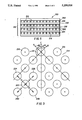
- FIG. 3 is a magnified plan view of a halftone pattern of X-radiation transmission apertures of type found in one preferred embodiment of the collimating grid.
- FIG. 4 is a magnified plan view of a hexagonal array of X-radiation transmission apertures of the type found in a second preferred embodiment of the collimating grid.
- FIG. 5 is an enlarged side sectional view of a preferred apertured multilayer radiographic collimating grid.
- FIG. 6 is a perspective view of a cassette housing containing the imaging assembly of FIG. 1.
- FIG. 1 a radiographic imaging assembly satisfying the requirements of the invention is shown consisting of an X-ray collimating grid 212, a front intensifying screen 201, a dual coated radiographic element 100, and a back intensifying screen 202.
- the radiographic element is comprised of a transparent film support, a front spectrally sensitized high tabularity silver halide emulsion layer unit coated on the support and located adjacent the front intensifying screen, a back spectrally sensitized high tabularity silver halide emulsion layer unit coated on the support and located adjacent the back intensifying screen, and means for reducing to less than 10 percent crossover to the front and back emulsion layers from the back and front screens, respectively, of radiation longer than 300 nm in wavelength.
- the radiographic element 100 is comprised of a transparent film support 101, typically blue tinted (a customary preference of radiologists), and optional subbing layer units 103 and 105, each of which can be formed of one or more adhesion promoting layers.
- a transparent film support 101 typically blue tinted (a customary preference of radiologists)
- optional subbing layer units 103 and 105 each of which can be formed of one or more adhesion promoting layers.
- On the first and second opposed major faces 107 and 109 of the subbing layer units are crossover reducing hydrophilic colloid layers 111 and 113, respectively.
- Overlying the crossover reducing layers 111 and 113 are light recording latent image forming silver halide emulsion layer units 115 and 117, respectively.
- Each of the emulsion layer units is formed of one or more hydrophilic colloid layers including at least one high tabularity silver halide emulsion layer.
- Overlying the emulsion layer units 115 and 117 are optional protective overcoat layers
- the front and back intensifying screens 201 and 202 are each capable of absorbing X-radiation and emitting electromagnetic radiation longer than 300 nm. To produce sharp images it is not only essential that the radiographic element exhibit low (less than 10 percent) crossover, it is also necessary that at least the front intensifying screen have the capacity to emit sharp image patterns The front screen therefore is chosen to exhibit modulation transfer factors greater than those of reference curve A in FIG. 2.
- the X-ray collimating grid 212 is located to receive X-radiation prior to the front screen 201. Typically some of the X-radiation reaching the grid has been absorbed and some deflected in passing through the imaging subject (e.g., the chest or abdomen of a medical patient).
- the function which the grid must perform is to minimize the deflection component of the X-radiation reaching the emulsion layer units. To accomplish this the grid must contain openings that allow the transmission of nondeflected X-radiation from the imaging subject to the radiographic element, and the openings must be formed by an X-ray opaque material capable of absorbing the deflected component of the X-radiation.
- the visual impact of the grid pattern on the radiographic image can be significantly reduced or eliminated by forming apertures with nonlinear boundaries in an X-radiation opaque material.
- the grid contains an array of at least 85 X-ray transmission apertures per inch providing at least 50 percent open area.
- Circular apertures are most convenient to construct and are preferred; however, apertures with nonlinear boundaries can take any convenient geometrical form that approximates a circular form--e.g., an elliptical or oval form. Generally any aperture having nonlinear boundaries and a ratio of maximum to minimum cross-sectional widths ranging from 1:1 to 3:2 is satisfactory for purposes of this invention. It is believed that the nonlinear boundaries of the apertures are responsible for visually obscuring the grid pattern as a component of the radiographic image. The restricted ratio of maximum to minimum cross-sectional widths insures that curved boundaries that approach linearity are excluded.
- the grids should have at least 85 radiation apertures per linear inch and an open area ranging from about 50 to about 70 percent, and more preferably, from 60 to 65 percent open area.
- the open area or openness of the X-ray opaque sheet reflects the amount of lead or other X-ray opaque material removed from the sheet in forming the apertures.
- the density of the radiation apertures should range from 85 to about 200 per linear inch.
- the density of the radiation apertures is from 85 to about 130 per linear inch, most preferably in the range from about 115 to about 130 apertures/linear inch.
- the number of apertures can be in the range of 180 to 200 per linear inch.
- the apertures can be arranged in any convenient array.
- the array can embody any of a variety of known patterns.
- the grid apertures are arranged in the form of a halftone pattern, as illustrated in FIG. 3.
- the term "halftone" is intended to denote a pattern in which a central aperture is equidistant from four adjacent apertures.
- central radiation aperture 222 has as its nearest four neighbors radiation apertures 224, 226, 228 and 230.
- the distances a, b, c and d between central aperture 222 and four neighboring apertures 224, 226, 228 and 230 are equal.
- angle AB angle between lines connecting the centers of the nearest neighbors
- Axes A and B each form 45° angles AC and BC, respectively, with axis C.
- AC and BC are preferably 45° angles, a workable range of angles is from 30° to 75°.
- a second preferred aperture pattern is the hexagonal pattern shown in FIG. 4.
- the hexagonal pattern consists of central apertures (e.g., aperture 231 and six nearest neighboring apertures 232, 234, 236, 238, 240 and 242 at distances a, b, c, d, e and f, between aperture centers which are equal. Notice that in the hexagonal pattern the adjacent apertures lie along one of three axis orientations and notice that the axes intersect at 60° angles.
- the grid consists of a stacked series of sheets comprised of an X-ray transparent support 218 which is preferably a polymeric film support of high dimensional integrity, such as poly(ethylene terephthalate, and an X-ray opaque layer 214 containing apertures 216.
- the sheets are assembled as a unitary element using adhesive layers 220 with an extra support 218 positioned on the top of the stack to protect the uppermost X-ray opaque layer.
- the apertures in the stacked layers are in alignment.
- the alignment can be a vertical alignment as shown or a focused alignment--that is the centers of apertures in the stack can be aligned along the direction of transmission of X-radiation.
- the grid can be formed of any desired number of stacked sheets. A convenient construction contains from 4 to 14 sheets with from 6 to 10 sheets being preferred. Further details of this preferred grid construction are provided by Moore et al U.S. Pat. No. 4,951,305, the disclosure of which is here incorporated by reference.
- the intensifying screens can take any convenient conventional form, provided at least the front screen exhibits modulation transfer factors (MTF) greater than those of reference curve A in FIG. 2.
- MTF modulation transfer factors
- Table I The numerical values of MTF are provided in Table I in the Examples below. From FIG. 2 and Table I it is apparent that MTF varies as a function of spatial frequency measured in cycles per millimeter (mm). MTF measurement for screen-film radiographic systems is described by Kunio Doi et al, "MTF and Wiener Spectra of Radiographic Screen-Film Systems", U.S. Department of Health and Human Services, pamphlet FDA 82-8187. The profile of the individual MTF factors over a range of cycles per mm constitutes a modulation transfer function. Preferred lower MTF limits for front and back screen employed for mammographic imaging applications are set out in FIG. 3 and Table III of Luckey et al U.S. Pat. No. 4,710,637, the disclosure of which is here incorporated by reference.
- the front and back intensifying screens each include a fluorescent layer comprised of a phosphor chosen from rare earth oxychalcogenide and halide phosphors of the formula:
- M is at least one of the metals yttrium, lanthanum, gadolinium, or lutetium,
- M' is at least one of the rare earth metals dysprosium, erbium, europium, holmium, neodymium, praseodymium, samarium, terbium, thulium, or ytterbium,
- X is a middle chalcogen (S, Se, or Te) or halogen
- n 0.0002 to 0.2
- w is 1 when X is halogen or 2 when X is chalcogen.
- phosphors include calcium tungstate, niobium-activated or thulium-activated yttrium tantalate, and terbium-activated gadolinium or lutetium oxysulfide.
- Calcium tungstate phosphors are illustrated by Wynd et al in U.S. Pat. No. 2,303,942.
- Niobium-activated and rare earth activated yttrium, lutetium and gadolinium tantalates are disclosed by Brixner in U.S. Pat. No. 4,225,653.
- Rare earth activated gadolinium and yttrium middle chalcogen phosphors are taught by Royce in U.S. Pat. No. 3,418,246.
- Rare earth activated lanthanum and lutetium middle chalcogen phosphors are illustrated by Yocom in U.S. Pat. No. 3,418,247.
- Terbium-activated lanthanium, gadolinium and lutetium oxysulfide phosphors are disclosed by Buchanan et al in U.S. Pat. No. 3,725,704. Cerium activated lanthanum oxychloride phosphors are taught by Swindells in U.S. Pat. No. 2,729,604. Terbium activated and optionally cerium activated lanthanum and gadolinium oxyhalide phosphors are disclosed by Rabatin in U.S. Pat. No. 3,617,743 and Ferri et al in U.S. Pat. No. 3,974,389. Rare earth activated rare earth oxyhalide phosphors are disclosed by Rabatin in U.S. Pat.
- Nonrare earth co-activators can be employed as illustrated by bismuth and ytterbium activated lanthanum oxychloride phosphors disclosed by Luckey et al in U.S. Pat. No. 4,311,487. The mixing of phosphors as well as the coating of phosphors in separate layers of the same screen are specifically recognized.
- a phosphor mixture of calcium tungstate and yttrium tantalate is disclosed by Patten in U.S. Pat. No. 4,387,141. However, in general neither mixtures nor multiple phosphor layers within a single screen are preferred or required.
- the phosphor layers need not contain separate binders, in most applications the phosphor layers contain sufficient binder to provide structural coherence to the phosphor layer.
- the binders useful in the practice of the invention are those conventionally employed in the art. Binders are generally chosen from a wide variety of known polymers which are transparent to X-radiation and emitted light.
- Binders commonly employed in the art include sodium o-sulfobenzaldehyde acetal of poly(vinyl alcohol), chlorosulfonated polyethylene; a mixture of macromolecular bisphenol polycarbonates and copolymers comprising bisphenol carbonates and poly(alkylene oxides); aqueous ethanol soluble nylons; poly(alkyl acrylates and methacrylates) and copolymers of poly(alkyl acrylates and methacrylates) with acrylic and methacrylic acids; poly(vinyl butyral); and polyurethane elastomers. These and other useful binders are disclosed in U.S. Pat. Nos.
- phosphor to binder ratios While a wide range of phosphor to binder ratios can be employed, generally thinner phosphor layers and sharper images are realized when a high weight ratio of phosphor to binder is employed.
- Preferred phosphor to binder ratios are in the range of from about 10:1 to 25:1 for screen constructions intended to equal commercial screen exposure repetitions without loss of structural integrity. For limited or single exposure applications it is, of course, appreciated that any minimal amount of binder consistent with structural integrity is satisfactory.
- the phosphor layer is modified to impart a small, but significant degree of light absorption. If the binder is chosen to exhibit the desired degree of light absorption, then no other ingredient of the phosphor layer is required to perform the light attenuation function. For example, a slightly yellow transparent polymer will absorb a significant fraction of phosphor emitted blue light. U/V absorption can be similarly achieved. It is specifically noted that the less structural complex chromophores for U/V absorption particularly lend themselves to incorporation in polymers.
- a separate absorber is incorporated in the phosphor layer to reduce its effective thickness.
- the absorber can be a dye or pigment capable of absorbing light within the spectrum emitted by the phosphor. Yellow dye or pigment selectively absorbs blue light emissions and is particularly useful with a blue emitting phosphor. On the other hand, a green emitting phosphor is better used in combination with magenta dyes and pigments.
- U/V emitting phosphors can be used with known U/V absorbers. Black dyes and pigments are, of course, generally useful with phosphors because of their broad absorption spectra. Carbon black is a preferred light absorber for incorporation in the phosphor layers. Luckey et al in U.S. Pat. No. 4,259,588, hereby incorporated by-reference, teach that increased sharpness can be achieved by incorporating a yellow dye in a terbium-activated gadolinium oxysulfide phosphor layer.
- Screen supports are most commonly film supports of high dimensional integrity, and include PET film supports, for example.
- the phosphor layer contains an absorber or a black surface is positioned adjacent the anticurl layer during exposure.
- a black polyvinyl chloride or paper sheet can be positioned adjacent the anticurl layer.
- the adjacent interior surface of the cassette in which the assembly is mounted is a black polyurethane or similar polymeric foam layer, which can be relied upon for light absorption contributing to image sharpness.
- the screen supports are not themselves black, best sharpness levels are realized when a black film or paper is interposed between the cassette and each screen of the image recording assembly.
- the front screen support and/or its subbing and anticurl layers can be black or suitably colored to absorb emitted light, thereby minimizing light reflection and image sharpness degradation.
- the back screen support as well as its subbing and anticurl layers can be of the same form as described for the front screen. If desired to increase speed, either or both of the front and back screen supports and/or their subbing or anticurl layers can be reflective of emitted light.
- a blue or white back screen support can be chosen to reflect light emitted by calcium tungstate or rare earth-activated yttrium tantalate or a green or white support can be chosen to reflect light emitted from a rare earth-activated lutetium gadolinium oxysulfide phosphor.
- Titania is preferably coated on or incorporated in the front and back screen supports to maximize reflection of green light.
- Metal layers such as aluminum can be used to enhance reflection.
- Paper supports, though less common for intensifying screens than film supports, are known and can be used for specific applications.
- Dyes and pigments are commonly loaded into supports to enhance absorption or reflection of light. Air can be trapped in supports to reflect U/V light.
- Intensifying screen supports and the subbing layers used to improve coating adhesion can be chosen from among those employed for silver halide photographic and radiographic elements, as illustrated by Research Disclosure, Item 17643, supra, Section XVII, and research Disclosure, Item 18431, supra, Section I, the disclosures of which are hereby incorporated-by-reference herein.
- overcoat though not required, is commonly located over the phosphor layer for humidity and wear protection.
- the overcoat can be chosen using the criteria described above in connection with the binder.
- the overcoat can be chosen from among the same polymers used to form either the screen binder or the support, with the requirements of toughness and scratch resistance usually favoring polymers conventionally employed for film supports.
- cellulose acetate is a preferred overcoat used with the preferred polyurethane binders.
- Overcoat polymers are often used also to seal the edges of the phosphor layer
- anticurl layers are not required for the intensifying screens, they are generally preferred for inclusion.
- the function of the anticurl layer is to balance the forces exerted by the layers coated on the opposite major surface of the screen support which if left unchecked, cause the screen to assume a non-planar configuration, e.g. to curl or roll-up on itself.
- Materials forming the anticurl layers can be chosen from among those identified above for use as binders and overcoats.
- an anticurl layer is formed for the same polymer as the overcoat on the opposite side of the support. For example, cellulose acetate is preferred for both overcoat and anticurl layers.
- the overcoats of the phosphor layers can include a matting agent, although more commonly employed in radiographic elements then with screens.
- a matting agent can be selected from those cited by Research Disclosure, Item 308119, December 1989, Section XVI.
- a variety of other optional materials can be included in the surface coatings of the intensifying screens, such as materials to reduce static electrical charge accumulation, plasticizers, lubricants, and the like. However, such materials are more commonly included in the radiographic elements which come into contact with the intensifying screens.
- the radiographic elements forming a part of the imaging assemblies of the invention contain in the front and back emulsion layer units at least one spectrally sensitized high tabularity silver halide emulsion, where "high tabularity" is defined as described in the Background section of the specification.
- high tabularity is defined as described in the Background section of the specification.
- tabularities range from 40 to 1000 although both higher and lower tabularities can be employed to advantage.
- Specifically preferred tabular grain emulsions are those in which greater than 50 percent, preferably at least 70 percent and optimally at least 90 percent of the total grain population is accounted for by tabular grains having a thickness of less than 0.3 ⁇ m and preferably less than 0.2 ⁇ m.
- the tabular grain emulsions are contemplated to have average aspect ratios (ECD/t) of at least 5 and preferably at least 8. Any conventional tabular grain emulsion satisfying these criteria can be employed, but for radiographic applications it is generally preferred to limit iodide concentrations to less than 5 mole percent, optimally less than 3 mole percent, based on total silver.
- any conventional dual coated radiographic element exhibiting low ( ⁇ 10%) crossover can be employed in the radiographic imaging assemblies of the invention. This means simply that of the light emitted by one intensifying screen adjacent one emulsion layer unit less than 10 percent reaches the emulsion layer unit on the opposite side of the support.
- Preferred dual coated radiographic elements are those than exhibit crossover of less than 5 percent and, optimally, measurable (zero) crossover. Techniques for crossover measurement are disclosed in Abbott et al U.S. Pat. Nos. 4,425,425 and 4,425,426, the disclosures of which are here incorporated by reference.
- Low crossover is preferably achieved by incorporating at least one crossover reducing layer between the support and an overlying emulsion layer unit in a radiographic element.
- preferred forms of the crossover reducing layers 111 and 113 are those disclosed by Dickerson et al U.S Pat. Nos. 4,803,150 and 4,900,652, here incorporated by reference.
- microcrystalline dyes capable of being decolorized during processing can be incorporated in hydrophilic colloid binders to form the crossover reducing layers.
- hydrophilic colloid binders to form the crossover reducing layers.
- Another technique for crossover reduction useful with blue emitting intensifying screens is to incorporate ⁇ phase silver iodide particles in the crossover reducing layers, as taught by Daubendiek et al U.S. Pat. No. 4,639,411.
- Dickerson et al U.S. Pat. No. 4,994,355 here incorporated by reference, demonstrates medical application advantages for such radiographic elements constructed with a first emulsion layer unit exhibiting a contrast of less than 2.0 and a second emulsion layer unit exhibiting a contrast of at least 2.5. Both contrasts were based on measurements at 0.25 and 2.0 above minimum density and with the first and second emulsion layer units each being coated on both sides of a transparent support, thereby allowing contrasts to be measured in a manner comparable to contrast measurements on symmetrical radiographic elements Dickerson et al U.S. Pat. No.
- Bunch et al U.S. Pat. No. 5,021,327 discloses extending asymmetry of the radiographic imaging assembly beyond asymmetry in the dual coated low crossover radiographic elements to differences in the photicity of the front emulsion layer unit and front screen as compared to the photicity of the back emulsion layer unit and back screen.
- Bunch et al discloses that improvements in detective quantum efficiencies (DQE), the ratio of input noise to output noise, can be improved by increasing the photicity of the back portion of the assembly to at least twice (preferably from 2 to 10 times) that of the front portion of the assembly.
- DQE detective quantum efficiencies
- photicity is the integrated product of (1) the total emission of the screen over the wavelength range to which the emulsion layer is responsive, (2) the sensitivity of the emulsion layer unit over this emission range, and (3) the transmittance of radiation between the screen and the adjacent emulsion layer unit over this emission range. Transmittance is typically near unity and can in this instance be ignored. Photicity is discussed in greater detail in Mees, The Theory of the Photographic process3rd Ed., Macmillan, 1966, at page 462. From the above definition of photicity it is apparent that the desired asymmetry in photicity can be realized with asymmetrical emulsion layer unit selections, asymmetrical screen selections or a combination.
- any one or combination of speed, contrast and photicity can be varied to achieve specific imaging advantages.
- FIG. 6 provides a view of a partially opened cassette 248 for bedside radiography.
- Cassette 248 includes a cover 250 to which the flexible stacked grid 212 and the front intensifying screen 201 are, as shown, attached, although attachment is optional.
- the radiographic element 100 and the back intensifying screen 202 are also present in the cassette When the cassette is closed for use all of the elements of the imaging assembly are held firmly in position by compression. Usually a compressible pad, not shown, is included for this purpose, although the same effect can be realized by constructing the cassette with a concave curvature of the cover and cooperating bottom surface of the cassette.
- the radiographic element 100 is removed from association with the intensifying screens and the scatter radiation reducing grid for processing in a rapid access processor, such as an RP-X-OmatTM processor, which is capable of producing an image bearing radiographic element dry to the touch in less than 90 seconds.
- Rapid access processors are disclosed by Barnes et al, U.S. Pat. No. 3,545,971 and Akio et al published European Patent Application 248,390.
- radiographic elements satisfying the requirements of the present invention are specifically identified as being those which are capable of emerging dry to the touch when processed in 90 seconds according to the following reference conditions:
- the development step employs the following developer:
- This screen has a composition and structure corresponding to that of a commercial, medium to high resolution screen. It consists of a terbium activated gadolinium oxysulfide phosphor having a median particle size of 5 to 6 ⁇ m coated on a blue dyed polyester support in a Permuthane polyurethane binder at a total phosphor coverage of 3.1 g/dm 2 at a phosphor to binder ratio of 19:1.
- This screen has a composition and structure corresponding to that of a commercial, high speed screen. It consists of a terbium activated gadolinium oxysulfide phosphor having a median particle size of 8 to 9 ⁇ m coated on a white pigmented polyester support in a Permuthane polyurethane binder at a total phosphor coverage of 13.3 g/dm 2 at a phosphor to binder ratio of 19:1.
- Radiographic element A was a dual coated radiographic element exhibiting near zero crossover.
- Radiographic element A was constructed of a low crossover support composite (LXO) consisting of a blue tinted transparent polyester film support on each side with a crossover reducing layer consisting of gelatin (0.52 g/m 2 ) containing 200 mg/m 2 of a processing solution bleachable arylidene dye (dye 59 of Dickerson et al U.S. Pat. No. 4,994,355).
- LXO low crossover support composite
- Low contrast (LC) and high contrast (HC) emulsion layers were coated on opposite sides of the support over the crossover reducing layers. Both emulsions were green-sensitized high tabularity silver bromide emulsions.
- the low contrast emulsion was a blend of three emulsions whereas the first emulsion exhibited an ECD of 3.0 ⁇ m and an average grain thickness of 0.13 ⁇ m, the second emulsion exhibited an ECD of 2.0 ⁇ m and an average grain thickness of 0.13 ⁇ m, while the third emulsion exhibited an ECD of 0.8 ⁇ m and an average thickness of 0.13 ⁇ m.
- the high contrast emulsion exhibited less polydispersity than the low contrast emulsion.
- Both the high and low contrast emulsions were spectrally sensitized with 400 mg/Ag mol of anhydro-5,5-dichloro-9-ethyl-3-3-bis(3-sulfopropyl)-oxacarbocyanine hydroxide, followed by 300 mg/Ag mol of potassium iodide.
- the emulsion layers were each coated with a silver coverage of 2.42 g/m 2 and a gelatin coverage of 3.22 g/m 2 .
- Protective gelatin layers (0.69 g/m 2 ) were coated over the emulsion layers.
- Each of the gelatin containing layers were hardened with bis(vinylsulfonylmethyl) ether at 1.5% of the total gelatin.
- Emulsion LC When coated as described above, but symmetrically, with Emulsion LC coated on both sides of the support and Emulsion HC omitted, using a pair of screens having the MTF characteristics of Curve A, Emulsion LC exhibited a relative log speed of 98 and an average contrast of 1.8. Similarly, Emulsion HC when coated symmetrically with Emulsion LC omitted exhibited a relative log speed of 85 with an average contrast of 3.0. The emulsion layer units thus differed in average contrast by 1.2 while differing in speed by 13 relative log speed units (or 0.13 log E).
- Element A When Element A was tested for crossover as described by Abbott et al in U.S. Pat. No. 4,425,425, it exhibited an apparent crossover of 2%. However, as explained by Abbott et al, there was no actual crossover, since this amount of apparent crossover is produced by direct X-ray absorption in the absence of crossover. Element A was labeled "(EmHC)LXOA(EmC)".
- Radiographic element B was a conventional double coated radiographic element exhibiting extended exposure latitude.
- Radiographic element B was constructed of a blue tinted transparent polyester film support lacking the crossover reducing layers of radiographic Element A.
- Identical emulsion layers (L) were coated on opposite sides of the support.
- the emulsion employed was a green sensitized polydispersed silver bromoiodide emulsion.
- the same spectral sensitizing dye was employed as in Element A, but only 42 mg/Ag mole was required, since the emulsion was not a high aspect ratio tabular grain emulsion, and therefore, required much less dye for substantially optimum sensitization.
- Each emulsion layer was coated to provide a silver coverage of 2.62 g/m 2 and a gelatin coverage of 2.85 g/m 2 .
- Protective gelatin layers (0.70 g/m 2 ) were coated over the emulsion layers. Each of the layers were hardened with bis(vinylsulfonylmethyl) ether at 0.5% of the total gelatin.
- Element B When Element B was tested for crossover as described by Abbott et al in U.S. Pat. No. 4,425,425, it exhibited a crossover of 25%. Element B was labeled "(Em. L)HXOB(Em. L)".
- Grid C1 was a standard linear array grid consisting of 103 lines per inch (hereinafter indicated as lpi) with a 8:1 grid ratio, where grid ratio is the ratio of the thickness of the grid (h) divided by the width (d) of the grid slat spacing. Generally, a higher grid ratio indicates a grid capable of producing sharper images.
- Grid E2 was constructed of 8 sheets each of which consisted of a 2 mil layer of lead foil laminated to a 4 mil layer of poly(ethylene terephthalate) film support.
- the lead foil was etched to form a halftone pattern of circular apertures (the pattern of FIG. 3).
- the apertures were 7 mils in diameter and were spaced 8.33 mils apart (center-to-center) spacing.
- the sheets contained 100 apertures per inch (hereinafter referred to as api). There were 10,000 apertures per square inch in each sheet.
- the grid was assembled by aligning the apertures of each sheet with those of the sheets stacked above and below. The sheets were then bonded together in alignment using a thermally activated adhesive.
- the resulting 8 sheet stack had a total thickness of 52 mils and a calculated grid ratio of approximately 6:1.
- the lead content of the grid was approximately 170 mg/cm 2 .
- the assemblies were exposed to 100 KVp X-radiation, varying either current (mA) or time, using a 3-phase Picker Medical (Model VTX-650) X-ray unit containing filtration up to 3 mm of aluminum. Four inches of Lucite were used as the source of scatter and a 41 inch focus to film distance.
- the development step employed the following developer:
- the assemblies were exposed to produce a maximum density of 1.2 in the radiographic elements after processing.
- the processed elements were examined for visibility of grid image patterns (artifacts) as shown in Table III below.
- V(EmHC)LXOA(EmLC)W was found to produce images of such sharpness that it produces a very noticeable image of the superimposed linear grid C1.
- the grid lines were observed to interfere with radiographic anatomical information, a quite undesirable characteristic. It was expected that objectionable grid patterns would be produced by the assembly using any variety of grids with similar grid ratios. Surprisingly however, it was found that with the use of the grid (E2) the superimposed grid image was only minimally noticeable.
Abstract
Description
ECD/t.sup.2 >25
M.sub.(w-n) M'.sub.n O.sub.w X
______________________________________
development      24 seconds at 35° C.,
fixing           20 seconds at 35° C.,
washing          10 seconds at 35° C., and
drying           20 seconds at 65° C.,
______________________________________
______________________________________
Hydroquinone           30     g
1-Phenyl-3-pyrazolidone
                       1.5    g
KOH                    21     g
NaHCO.sub.3            7.5    g
K.sub.2 SO.sub.3       44.2   g
Na.sub.2 S.sub.2 O.sub.5
                       12.6   g
NaBr                   35     g
5-Methylbenzotriazole  0.06   g
Glutaraldehyde         4.9    g
______________________________________
______________________________________
Ammonium thiosulfate 60%
                        260.0  g
Sodium bisulfate        180.0  g
Boric acid              25.0   g
Acetic acid             10.0   g
Aluminum sulfate        8.0    g
Water to 1 liter at pH
3.9 to 4.5
______________________________________
TABLE I ______________________________________ Modulation Transfer Factors of Screens % Modulation Transfer Factor at Various Cycles per mm ______________________________________ Scrn. 0 1.0 2.0 3.0 4.0 5.0 ______________________________________V 100 87.7 68.5 52.8 40.3 30.6W 100 47.1 20.8 11.0 6.8 4.5 A 100 63.6 33.0 18.9 11.4 7.8 ______________________________________ Scrn 6.0 7.0 8.0 9.0 10.0 ______________________________________ V 23.5 18.4 14.8 12.0 9.8 W 3.1 2.4 1.9 1.5 1.3 A 5.6 4.2 3.2 2.5 2.0 ______________________________________
              TABLE II
______________________________________
Grid/Screen/Film/Screen Assembly
______________________________________
1.       [(C1) 100 lpi linear]V
                            (Control)
         (EmL)HXOB(EmL)W
2.       [(E2) 100 api halftone]V
                            (Control)
         (EmL)HXOB(EmL)W
3.       [(C1) 100 lpi linear]V
                            (Control)
         (EmHC)LXOA(EmLC)W
4.       [(E2) 100 api halftone]V
                            (Example)
         (EmHC)LXOA(EmLC)W
______________________________________
______________________________________
development      24 seconds at 35° C.,
fixing           20 seconds at 35° C.,
washing          10 seconds at 35° C., and
drying           20 seconds at 65° C.,
______________________________________
______________________________________
Hydroquinone           30     g
1-Phenyl-3-pyrazolidone
                       1.5    g
KOH                    21     g
NaHCO.sub.3            7.5    g
K.sub.2 SO.sub.3       44.2   g
Na.sub.2 S.sub.2 O.sub.5
                       12.6   g
NaBr                   35     g
5-Methylbenzotriazole  0.06   g
Glutaraldehyde         4.9    g
______________________________________
______________________________________
Ammonium thiosulfate 60%
                        260.0  g
Sodium bisulfate        180.0  g
Boric acid              25.0   g
Acetic acid             10.0   g
Aluminum sulfate        8.0    g
Water to 1 liter at pH
3.9 to 4.5
______________________________________
              TABLE III
______________________________________
       Assembly  Subjective Rating*
______________________________________
1.       (Control)    3 (slightly noticeable)
2.       (Control)    1 (minimally noticeable)
3.       (Control)   10 (very noticeable)
4.       (Example)    2 (minimally noticeable)
______________________________________
 *Ranging from 1 to 10 with the 1 being the least noticeable and 10 being
 the most noticeable
Claims (19)
M.sub.(w-n) M'.sub.n O.sub.w X
Priority Applications (1)
| Application Number | Priority Date | Filing Date | Title |
|---|---|---|---|
| US07/965,147 US5259016A (en) | 1992-10-22 | 1992-10-22 | Assembly for radiographic imaging |
Applications Claiming Priority (1)
| Application Number | Priority Date | Filing Date | Title |
|---|---|---|---|
| US07/965,147 US5259016A (en) | 1992-10-22 | 1992-10-22 | Assembly for radiographic imaging |
Publications (1)
| Publication Number | Publication Date |
|---|---|
| US5259016A true US5259016A (en) | 1993-11-02 |
Family
ID=25509521
Family Applications (1)
| Application Number | Title | Priority Date | Filing Date |
|---|---|---|---|
| US07/965,147 Expired - Lifetime US5259016A (en) | 1992-10-22 | 1992-10-22 | Assembly for radiographic imaging |
Country Status (1)
| Country | Link |
|---|---|
| US (1) | US5259016A (en) |
Cited By (8)
| Publication number | Priority date | Publication date | Assignee | Title |
|---|---|---|---|---|
| EP0800078A2 (en) * | 1996-04-04 | 1997-10-08 | Hitachi, Ltd. | Non-destructive inspection apparatus and inspection system using it |
| US5716774A (en) * | 1996-09-30 | 1998-02-10 | Eastman Kodak Company | Radiographic elements containing ultrathin tabular grain emulsions |
| US6366643B1 (en) | 1998-10-29 | 2002-04-02 | Direct Radiography Corp. | Anti scatter radiation grid for a detector having discreet sensing elements |
| US6472137B1 (en) * | 1999-11-26 | 2002-10-29 | Agfa-Gevaert | Light-sensitive silver halide photographic film material and radiographic intensifying screen-film combination |
| US20030063708A1 (en) * | 2001-10-02 | 2003-04-03 | Takehiko Shoji | Cassette for radiographic imaging, radiographic image reading apparatus and radiographic image reading method |
| US6690767B2 (en) | 1998-10-29 | 2004-02-10 | Direct Radiography Corp. | Prototile motif for anti-scatter grids |
| US20070023667A1 (en) * | 2005-07-13 | 2007-02-01 | Canon Kabushiki Kaisha | Portable radiographic imaging apparatus |
| US20140339443A1 (en) * | 2011-11-25 | 2014-11-20 | Zhiping Mu | Collimating apparatus for emission tomography |
Citations (19)
| Publication number | Priority date | Publication date | Assignee | Title |
|---|---|---|---|---|
| US2133385A (en) * | 1937-05-08 | 1938-10-18 | Antony P Freeman | X-ray grid and method of making same |
| US2806958A (en) * | 1954-01-21 | 1957-09-17 | Gen Electric | Radiographic diaphragm and method of making the same |
| US3919559A (en) * | 1972-08-28 | 1975-11-11 | Minnesota Mining & Mfg | Louvered film for unidirectional light from a point source |
| US4127398A (en) * | 1963-09-18 | 1978-11-28 | Ni-Tec, Inc. | Multiple-channel tubular devices |
| US4288697A (en) * | 1979-05-03 | 1981-09-08 | Albert Richard D | Laminate radiation collimator |
| US4389729A (en) * | 1981-12-15 | 1983-06-21 | American Science And Engineering, Inc. | High resolution digital radiography system |
| US4425425A (en) * | 1981-11-12 | 1984-01-10 | Eastman Kodak Company | Radiographic elements exhibiting reduced crossover |
| US4425426A (en) * | 1982-09-30 | 1984-01-10 | Eastman Kodak Company | Radiographic elements exhibiting reduced crossover |
| US4710637A (en) * | 1986-02-10 | 1987-12-01 | Eastman Kodak Company | High efficiency fluorescent screen pair for use in low energy X radiation imaging |
| US4803150A (en) * | 1986-12-23 | 1989-02-07 | Eastman Kodak Company | Radiographic element exhibiting reduced crossover |
| US4900652A (en) * | 1987-07-13 | 1990-02-13 | Eastman Kodak Company | Radiographic element |
| US4951305A (en) * | 1989-05-30 | 1990-08-21 | Eastman Kodak Company | X-ray grid for medical radiography and method of making and using same |
| US4969176A (en) * | 1988-03-18 | 1990-11-06 | U.S. Philips Corporation | X-ray examination apparatus having a stray radiation grid with anti-vignetting effect |
| US4994355A (en) * | 1989-07-26 | 1991-02-19 | Eastman Kodak Company | Radiographic elements with selected contrast relationships |
| US4997750A (en) * | 1989-02-23 | 1991-03-05 | Eastman Kodak Company | Radiographic elements with selected speed relationships |
| US5008920A (en) * | 1989-11-27 | 1991-04-16 | Liebel-Flarsheim Company | X-ray film cassette with flexible grid bonded to prestressed cover |
| US5021327A (en) * | 1989-06-29 | 1991-06-04 | Eastman Kodak Company | Radiographic screen/film assemblies with improved detection quantum efficiencies |
| US5033046A (en) * | 1989-09-22 | 1991-07-16 | Romero Jose M | Device of x-ray intensifying and anti-diffusion screens for intra-oral dental radiographic plates |
| US5108881A (en) * | 1990-03-29 | 1992-04-28 | Eastman Kodak Company | Minimal crossover radiographic elements adapted for varied intensifying screen exposures |
-
1992
- 1992-10-22 US US07/965,147 patent/US5259016A/en not_active Expired - Lifetime
Patent Citations (20)
| Publication number | Priority date | Publication date | Assignee | Title |
|---|---|---|---|---|
| US2133385A (en) * | 1937-05-08 | 1938-10-18 | Antony P Freeman | X-ray grid and method of making same |
| US2806958A (en) * | 1954-01-21 | 1957-09-17 | Gen Electric | Radiographic diaphragm and method of making the same |
| US4127398A (en) * | 1963-09-18 | 1978-11-28 | Ni-Tec, Inc. | Multiple-channel tubular devices |
| US3919559A (en) * | 1972-08-28 | 1975-11-11 | Minnesota Mining & Mfg | Louvered film for unidirectional light from a point source |
| US4288697A (en) * | 1979-05-03 | 1981-09-08 | Albert Richard D | Laminate radiation collimator |
| US4425425A (en) * | 1981-11-12 | 1984-01-10 | Eastman Kodak Company | Radiographic elements exhibiting reduced crossover |
| US4389729A (en) * | 1981-12-15 | 1983-06-21 | American Science And Engineering, Inc. | High resolution digital radiography system |
| US4425426A (en) * | 1982-09-30 | 1984-01-10 | Eastman Kodak Company | Radiographic elements exhibiting reduced crossover |
| US4425426B1 (en) * | 1982-09-30 | 1988-08-09 | ||
| US4710637A (en) * | 1986-02-10 | 1987-12-01 | Eastman Kodak Company | High efficiency fluorescent screen pair for use in low energy X radiation imaging |
| US4803150A (en) * | 1986-12-23 | 1989-02-07 | Eastman Kodak Company | Radiographic element exhibiting reduced crossover |
| US4900652A (en) * | 1987-07-13 | 1990-02-13 | Eastman Kodak Company | Radiographic element |
| US4969176A (en) * | 1988-03-18 | 1990-11-06 | U.S. Philips Corporation | X-ray examination apparatus having a stray radiation grid with anti-vignetting effect |
| US4997750A (en) * | 1989-02-23 | 1991-03-05 | Eastman Kodak Company | Radiographic elements with selected speed relationships |
| US4951305A (en) * | 1989-05-30 | 1990-08-21 | Eastman Kodak Company | X-ray grid for medical radiography and method of making and using same |
| US5021327A (en) * | 1989-06-29 | 1991-06-04 | Eastman Kodak Company | Radiographic screen/film assemblies with improved detection quantum efficiencies |
| US4994355A (en) * | 1989-07-26 | 1991-02-19 | Eastman Kodak Company | Radiographic elements with selected contrast relationships |
| US5033046A (en) * | 1989-09-22 | 1991-07-16 | Romero Jose M | Device of x-ray intensifying and anti-diffusion screens for intra-oral dental radiographic plates |
| US5008920A (en) * | 1989-11-27 | 1991-04-16 | Liebel-Flarsheim Company | X-ray film cassette with flexible grid bonded to prestressed cover |
| US5108881A (en) * | 1990-03-29 | 1992-04-28 | Eastman Kodak Company | Minimal crossover radiographic elements adapted for varied intensifying screen exposures |
Cited By (14)
| Publication number | Priority date | Publication date | Assignee | Title |
|---|---|---|---|---|
| EP0800078A2 (en) * | 1996-04-04 | 1997-10-08 | Hitachi, Ltd. | Non-destructive inspection apparatus and inspection system using it |
| EP0800078A3 (en) * | 1996-04-04 | 1999-02-03 | Hitachi, Ltd. | Non-destructive inspection apparatus and inspection system using it |
| US5933473A (en) * | 1996-04-04 | 1999-08-03 | Hitachi, Ltd. | Non-destructive inspection apparatus and inspection system using it |
| US6049586A (en) * | 1996-04-04 | 2000-04-11 | Hitachi, Ltd. | Non-destructive inspection apparatus and inspection system using it |
| US6333962B1 (en) | 1996-04-04 | 2001-12-25 | Hitachi, Ltd. | Non-destructive inspection apparatus and inspection system using it |
| US5716774A (en) * | 1996-09-30 | 1998-02-10 | Eastman Kodak Company | Radiographic elements containing ultrathin tabular grain emulsions |
| US6366643B1 (en) | 1998-10-29 | 2002-04-02 | Direct Radiography Corp. | Anti scatter radiation grid for a detector having discreet sensing elements |
| US6690767B2 (en) | 1998-10-29 | 2004-02-10 | Direct Radiography Corp. | Prototile motif for anti-scatter grids |
| US6472137B1 (en) * | 1999-11-26 | 2002-10-29 | Agfa-Gevaert | Light-sensitive silver halide photographic film material and radiographic intensifying screen-film combination |
| US20030063708A1 (en) * | 2001-10-02 | 2003-04-03 | Takehiko Shoji | Cassette for radiographic imaging, radiographic image reading apparatus and radiographic image reading method |
| US6969861B2 (en) * | 2001-10-02 | 2005-11-29 | Konica Corporation | Cassette for radiographic imaging, radiographic image reading apparatus and radiographic image reading method |
| US20070023667A1 (en) * | 2005-07-13 | 2007-02-01 | Canon Kabushiki Kaisha | Portable radiographic imaging apparatus |
| US7429131B2 (en) * | 2005-07-13 | 2008-09-30 | Canon Kabushiki Kaisha | Portable radiographic imaging apparatus |
| US20140339443A1 (en) * | 2011-11-25 | 2014-11-20 | Zhiping Mu | Collimating apparatus for emission tomography |
Similar Documents
| Publication | Publication Date | Title |
|---|---|---|
| US4710637A (en) | High efficiency fluorescent screen pair for use in low energy X radiation imaging | |
| US5285490A (en) | Imaging combination for detecting soft tissue anomalies | |
| US5475229A (en) | Radiographic intensifying screen | |
| US4865944A (en) | Unitary intensifying screen and radiographic element | |
| JP3479574B2 (en) | Radiation intensifying screen and radiation intensifying screen assembly for front side | |
| US5259016A (en) | Assembly for radiographic imaging | |
| US5461660A (en) | Medical X-ray recording system | |
| US5460916A (en) | Silver halide photographic material and method of forming radiation image using said material | |
| US6457860B1 (en) | Light-weight imaging assemblies for oncology portal imaging | |
| US5482813A (en) | Radiological image forming method | |
| EP0486783B1 (en) | Mixed phosphor X-ray intensifying screens with improved resolution | |
| EP0994388A1 (en) | Medical diagnostic film for soft tissue imaging (II) | |
| US6042986A (en) | Portal localization radiographic element and method of imaging | |
| EP0627744A2 (en) | Improved radiological system employing phospors of different densities | |
| US6967071B2 (en) | High speed radiographic imaging assembly | |
| US7005226B2 (en) | High speed imaging assembly for radiography | |
| EP1422561B1 (en) | Radiographic imaging assembly for mammography | |
| EP0559578A1 (en) | Means for assuring proper orientation of the film in an asymmetrical radiographic assembly | |
| EP0232888B1 (en) | High efficiency fluorescent screen pair for use in low energy x radiation imaging | |
| US6828077B2 (en) | Mammography imaging method using high peak voltage | |
| US6864045B2 (en) | Mammography film and imaging assembly for use with rhodium or tungsten anodes | |
| US20040096028A1 (en) | Mammography imaging method using high peak voltage and rhodium or tungsten anodes | |
| EP1422557A1 (en) | Mammography film and imaging assembly for use with rhodium or tungsten anodes | |
| CA2143694A1 (en) | Method of autoradiographic imaging | |
| JPH07301697A (en) | Radiographic fluorescent intensifying screen |
Legal Events
| Date | Code | Title | Description |
|---|---|---|---|
| AS | Assignment |
Owner name: EASTMAN KODAK COMPANY, NEW YORK Free format text: ASSIGNMENT OF ASSIGNORS INTEREST.;ASSIGNORS:DICKERSON, ROBERT E.;BUNCH, PHILLIP C.;STEKLENSKI, DAVID E.;REEL/FRAME:006347/0464 Effective date: 19921016 |
|
| FEPP | Fee payment procedure |
Free format text: PAYOR NUMBER ASSIGNED (ORIGINAL EVENT CODE: ASPN); ENTITY STATUS OF PATENT OWNER: LARGE ENTITY |
|
| AS | Assignment |
Owner name: EASTMAN KODAK COMPANY, NEW YORK Free format text: RE-RECORD OF INSTRUMENT PREVIOUSLY RECORDED ON OCTOBER 22, 1992, AND TO CORRECT THE ASSIGNOR'S NAME.;ASSIGNORS:DICKERSON, ROBERT E.;BUNCH, PHILLIP C.;STEKLENSKI, DAVID J.;REEL/FRAME:006550/0023 Effective date: 19921016 |
|
| STCF | Information on status: patent grant |
Free format text: PATENTED CASE |
|
| FEPP | Fee payment procedure |
Free format text: PAYOR NUMBER ASSIGNED (ORIGINAL EVENT CODE: ASPN); ENTITY STATUS OF PATENT OWNER: LARGE ENTITY Free format text: PAYER NUMBER DE-ASSIGNED (ORIGINAL EVENT CODE: RMPN); ENTITY STATUS OF PATENT OWNER: LARGE ENTITY |
|
| FPAY | Fee payment |
Year of fee payment: 4 |
|
| FPAY | Fee payment |
Year of fee payment: 8 |
|
| FPAY | Fee payment |
Year of fee payment: 12 |
|
| AS | Assignment |
Owner name: CREDIT SUISSE, CAYMAN ISLANDS BRANCH, AS ADMINISTR Free format text: FIRST LIEN OF INTELLECTUAL PROPERTY SECURITY AGREEMENT;ASSIGNOR:CARESTREAM HEALTH, INC.;REEL/FRAME:019649/0454 Effective date: 20070430 Owner name: CREDIT SUISSE, CAYMAN ISLANDS BRANCH, AS ADMINISTR Free format text: SECOND LIEN INTELLECTUAL PROPERTY SECURITY AGREEME;ASSIGNOR:CARESTREAM HEALTH, INC.;REEL/FRAME:019773/0319 Effective date: 20070430 |
|
| AS | Assignment |
Owner name: CARESTREAM HEALTH, INC., NEW YORK Free format text: ASSIGNMENT OF ASSIGNORS INTEREST;ASSIGNOR:EASTMAN KODAK COMPANY;REEL/FRAME:020741/0126 Effective date: 20070501 Owner name: CARESTREAM HEALTH, INC., NEW YORK Free format text: ASSIGNMENT OF ASSIGNORS INTEREST;ASSIGNOR:EASTMAN KODAK COMPANY;REEL/FRAME:020756/0500 Effective date: 20070501 Owner name: CARESTREAM HEALTH, INC.,NEW YORK Free format text: ASSIGNMENT OF ASSIGNORS INTEREST;ASSIGNOR:EASTMAN KODAK COMPANY;REEL/FRAME:020741/0126 Effective date: 20070501 Owner name: CARESTREAM HEALTH, INC.,NEW YORK Free format text: ASSIGNMENT OF ASSIGNORS INTEREST;ASSIGNOR:EASTMAN KODAK COMPANY;REEL/FRAME:020756/0500 Effective date: 20070501 |
|
| AS | Assignment |
Owner name: CARESTREAM HEALTH, INC., NEW YORK Free format text: RELEASE OF SECURITY INTEREST IN INTELLECTUAL PROPERTY (FIRST LIEN);ASSIGNOR:CREDIT SUISSE AG, CAYMAN ISLANDS BRANCH;REEL/FRAME:026069/0012 Effective date: 20110225 |
|
| AS | Assignment |
Owner name: CREDIT SUISSE AG, CAYMAN ISLANDS BRANCH, NEW YORK Free format text: INTELLECTUAL PROPERTY SECURITY AGREEMENT;ASSIGNORS:CARESTREAM HEALTH, INC.;CARESTREAM DENTAL, LLC;QUANTUM MEDICAL IMAGING, L.L.C.;AND OTHERS;REEL/FRAME:026269/0411 Effective date: 20110225 |
|
| AS | Assignment |
Owner name: CARESTREAM HEALTH, INC., NEW YORK Free format text: RELEASE OF SECURITY INTEREST IN INTELLECTUAL PROPERTY (SECOND LIEN);ASSIGNOR:CREDIT SUISSE AG, CAYMAN ISLANDS BRANCH;REEL/FRAME:027851/0812 Effective date: 20110225 |
|
| AS | Assignment |
Owner name: TROPHY DENTAL INC., GEORGIA Free format text: RELEASE BY SECURED PARTY;ASSIGNOR:CREDIT SUISSE AG, CAYMAN ISLANDS BRANCH;REEL/FRAME:061681/0380 Effective date: 20220930 Owner name: QUANTUM MEDICAL HOLDINGS, LLC, NEW YORK Free format text: RELEASE BY SECURED PARTY;ASSIGNOR:CREDIT SUISSE AG, CAYMAN ISLANDS BRANCH;REEL/FRAME:061681/0380 Effective date: 20220930 Owner name: QUANTUM MEDICAL IMAGING, L.L.C., NEW YORK Free format text: RELEASE BY SECURED PARTY;ASSIGNOR:CREDIT SUISSE AG, CAYMAN ISLANDS BRANCH;REEL/FRAME:061681/0380 Effective date: 20220930 Owner name: CARESTREAM DENTAL, LLC, GEORGIA Free format text: RELEASE BY SECURED PARTY;ASSIGNOR:CREDIT SUISSE AG, CAYMAN ISLANDS BRANCH;REEL/FRAME:061681/0380 Effective date: 20220930 Owner name: CARESTREAM HEALTH, INC., NEW YORK Free format text: RELEASE BY SECURED PARTY;ASSIGNOR:CREDIT SUISSE AG, CAYMAN ISLANDS BRANCH;REEL/FRAME:061681/0380 Effective date: 20220930 |