US5258917A - Method for nesting contours to be cut out of natural leather - Google Patents
Method for nesting contours to be cut out of natural leather Download PDFInfo
- Publication number
- US5258917A US5258917A US07/688,908 US68890891A US5258917A US 5258917 A US5258917 A US 5258917A US 68890891 A US68890891 A US 68890891A US 5258917 A US5258917 A US 5258917A
- Authority
- US
- United States
- Prior art keywords
- defect
- contours
- defects
- degree
- color
- Prior art date
- Legal status (The legal status is an assumption and is not a legal conclusion. Google has not performed a legal analysis and makes no representation as to the accuracy of the status listed.)
- Expired - Lifetime
Links
Images


Classifications
-
- B—PERFORMING OPERATIONS; TRANSPORTING
- B26—HAND CUTTING TOOLS; CUTTING; SEVERING
- B26D—CUTTING; DETAILS COMMON TO MACHINES FOR PERFORATING, PUNCHING, CUTTING-OUT, STAMPING-OUT OR SEVERING
- B26D5/00—Arrangements for operating and controlling machines or devices for cutting, cutting-out, stamping-out, punching, perforating, or severing by means other than cutting
- B26D5/007—Control means comprising cameras, vision or image processing systems
-
- B—PERFORMING OPERATIONS; TRANSPORTING
- B23—MACHINE TOOLS; METAL-WORKING NOT OTHERWISE PROVIDED FOR
- B23K—SOLDERING OR UNSOLDERING; WELDING; CLADDING OR PLATING BY SOLDERING OR WELDING; CUTTING BY APPLYING HEAT LOCALLY, e.g. FLAME CUTTING; WORKING BY LASER BEAM
- B23K26/00—Working by laser beam, e.g. welding, cutting or boring
- B23K26/02—Positioning or observing the workpiece, e.g. with respect to the point of impact; Aligning, aiming or focusing the laser beam
- B23K26/03—Observing, e.g. monitoring, the workpiece
- B23K26/032—Observing, e.g. monitoring, the workpiece using optical means
-
- B—PERFORMING OPERATIONS; TRANSPORTING
- B23—MACHINE TOOLS; METAL-WORKING NOT OTHERWISE PROVIDED FOR
- B23K—SOLDERING OR UNSOLDERING; WELDING; CLADDING OR PLATING BY SOLDERING OR WELDING; CUTTING BY APPLYING HEAT LOCALLY, e.g. FLAME CUTTING; WORKING BY LASER BEAM
- B23K26/00—Working by laser beam, e.g. welding, cutting or boring
- B23K26/08—Devices involving relative movement between laser beam and workpiece
- B23K26/0869—Devices involving movement of the laser head in at least one axial direction
- B23K26/0876—Devices involving movement of the laser head in at least one axial direction in at least two axial directions
-
- B—PERFORMING OPERATIONS; TRANSPORTING
- B23—MACHINE TOOLS; METAL-WORKING NOT OTHERWISE PROVIDED FOR
- B23K—SOLDERING OR UNSOLDERING; WELDING; CLADDING OR PLATING BY SOLDERING OR WELDING; CUTTING BY APPLYING HEAT LOCALLY, e.g. FLAME CUTTING; WORKING BY LASER BEAM
- B23K26/00—Working by laser beam, e.g. welding, cutting or boring
- B23K26/36—Removing material
- B23K26/38—Removing material by boring or cutting
-
- B—PERFORMING OPERATIONS; TRANSPORTING
- B26—HAND CUTTING TOOLS; CUTTING; SEVERING
- B26D—CUTTING; DETAILS COMMON TO MACHINES FOR PERFORATING, PUNCHING, CUTTING-OUT, STAMPING-OUT OR SEVERING
- B26D5/00—Arrangements for operating and controlling machines or devices for cutting, cutting-out, stamping-out, punching, perforating, or severing by means other than cutting
- B26D5/005—Computer numerical control means
-
- B—PERFORMING OPERATIONS; TRANSPORTING
- B26—HAND CUTTING TOOLS; CUTTING; SEVERING
- B26F—PERFORATING; PUNCHING; CUTTING-OUT; STAMPING-OUT; SEVERING BY MEANS OTHER THAN CUTTING
- B26F1/00—Perforating; Punching; Cutting-out; Stamping-out; Apparatus therefor
- B26F1/38—Cutting-out; Stamping-out
-
- B—PERFORMING OPERATIONS; TRANSPORTING
- B27—WORKING OR PRESERVING WOOD OR SIMILAR MATERIAL; NAILING OR STAPLING MACHINES IN GENERAL
- B27G—ACCESSORY MACHINES OR APPARATUS FOR WORKING WOOD OR SIMILAR MATERIALS; TOOLS FOR WORKING WOOD OR SIMILAR MATERIALS; SAFETY DEVICES FOR WOOD WORKING MACHINES OR TOOLS
- B27G1/00—Machines or devices for removing knots or other irregularities or for filling-up holes
-
- C—CHEMISTRY; METALLURGY
- C14—SKINS; HIDES; PELTS; LEATHER
- C14B—MECHANICAL TREATMENT OR PROCESSING OF SKINS, HIDES OR LEATHER IN GENERAL; PELT-SHEARING MACHINES; INTESTINE-SPLITTING MACHINES
- C14B17/00—Details of apparatus or machines for manufacturing or treating skins, hides, leather, or furs
- C14B17/005—Inspecting hides or furs
-
- C—CHEMISTRY; METALLURGY
- C14—SKINS; HIDES; PELTS; LEATHER
- C14B—MECHANICAL TREATMENT OR PROCESSING OF SKINS, HIDES OR LEATHER IN GENERAL; PELT-SHEARING MACHINES; INTESTINE-SPLITTING MACHINES
- C14B5/00—Clicking, perforating, or cutting leather
-
- G—PHYSICS
- G01—MEASURING; TESTING
- G01N—INVESTIGATING OR ANALYSING MATERIALS BY DETERMINING THEIR CHEMICAL OR PHYSICAL PROPERTIES
- G01N33/00—Investigating or analysing materials by specific methods not covered by groups G01N1/00 - G01N31/00
- G01N33/44—Resins; rubber; leather
- G01N33/447—Leather
-
- B—PERFORMING OPERATIONS; TRANSPORTING
- B26—HAND CUTTING TOOLS; CUTTING; SEVERING
- B26D—CUTTING; DETAILS COMMON TO MACHINES FOR PERFORATING, PUNCHING, CUTTING-OUT, STAMPING-OUT OR SEVERING
- B26D7/00—Details of apparatus for cutting, cutting-out, stamping-out, punching, perforating, or severing by means other than cutting
- B26D2007/0012—Details, accessories or auxiliary or special operations not otherwise provided for
- B26D2007/0068—Trimming and removing web edges
-
- B—PERFORMING OPERATIONS; TRANSPORTING
- B26—HAND CUTTING TOOLS; CUTTING; SEVERING
- B26F—PERFORATING; PUNCHING; CUTTING-OUT; STAMPING-OUT; SEVERING BY MEANS OTHER THAN CUTTING
- B26F3/00—Severing by means other than cutting; Apparatus therefor
- B26F3/004—Severing by means other than cutting; Apparatus therefor by means of a fluid jet
-
- Y—GENERAL TAGGING OF NEW TECHNOLOGICAL DEVELOPMENTS; GENERAL TAGGING OF CROSS-SECTIONAL TECHNOLOGIES SPANNING OVER SEVERAL SECTIONS OF THE IPC; TECHNICAL SUBJECTS COVERED BY FORMER USPC CROSS-REFERENCE ART COLLECTIONS [XRACs] AND DIGESTS
- Y10—TECHNICAL SUBJECTS COVERED BY FORMER USPC
- Y10S—TECHNICAL SUBJECTS COVERED BY FORMER USPC CROSS-REFERENCE ART COLLECTIONS [XRACs] AND DIGESTS
- Y10S83/00—Cutting
- Y10S83/929—Particular nature of work or product
- Y10S83/936—Cloth or leather
- Y10S83/939—Cloth or leather with work support
Definitions
- the present invention relates to a method of optimally nesting the contours of parts to be cut out of a piece of natural leather.
- EP OS 0 277 066 For further automating the nesting process, particularly for natural leather, it is known from EP OS 0 277 066 to mark the defective places in the leather and to have them processed directly under the control of the cutting system.
- the defects are marked by the operator by fluorescent means.
- the marked places are detected by a camera and transmitted to a computer system which is provided with a stamping program for stamping out a given set of contours.
- the detected markings are interpreted by the computer system and are suitably taken into consideration as constraints upon the stamping program, so that the prescribed contours can then be stamped out automatically without defects being present in the material at places which cannot be tolerated.
- different markings are used by the operator for different qualities of defects, and these different markings can then be taken into consideration later on.
- the central object of the present invention is to develop a method for nesting contours to be cut out of natural leather which can be carried out without requiring any manual steps, from the initial detection of the defects in the leather, up to the final cutting step.
- This object may be achieved by a method for nesting contours to be cut out of a piece of natural leather comprising the steps of:
- regions in the stored contours of the parts to be cut out said regions having respective degree-of-defect ranges, which specify a maximum degree of defect to be accepted in each said region;
- the locations of the defects in the structure or material of the leather are detected by the camera or optical device as a function of the degree of the defect, which is correlated in turn to different shades of detected color. Regions corresponding to a given shade or color corresponding to a given degree of defect may be associated with the contours to be cut out, and stored in the control unit, whereby an automatic comparison can be effected as to whether the contours to be cut later on will contain only defects which can be tolerated.
- each individual skin is scanned initially, then a cutting program can be established and stored individually for each skin. In this way, the nesting can be optimized over a very large number of skins which can be placed in a goods storage area until they are ready to be used, for a very efficient cutting process. Since each skin then has a given cutting program associated with it, the nesting process and the cutting process can be separated from each other by a period of time which is as long as desired.
- the degree of utilization can be optimized over a correspondingly large number of skins.
- the optimizing is extended to a day's, week's or month's production of a cutting plant.
- the optical detection system may include a black-and-white camera or a color camera.
- colors of correspondingly higher color temperatures may be recorded by the camera.
- a color camera it is possible to grade the individual degrees of defects more precisely and provide additional criteria to optimize the nesting process.
- colors of higher temperature may be defined to include all colors of lower temperature so that an acceptance range (Gmax>G4>G3>. . . >G1) of degrees of defect (FG1, . . . , FGmax) is created, the acceptance range (Gn) permissible in each case including all lower and equal degrees of the detected defects (FG1, . . . , FGn-1; FGn)
- the optical detection system may include a laser scanner which detects the outer contour and/or the defects.
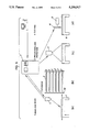
- FIG. 1 shows a laying table with an electronic camera arranged above it
- FIG. 2 shows an electronically controlled high-pressure, fluid-jet or laser-beam cutting system
- FIG. 3 shows the cutting system of FIG. 2 with a projector arranged above it;
- FIGS. 4, 4a show, by way of example, two contours which are to be cut out from a piece of natural leather
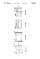
- FIGS. 5-5D show diagrammatically a series of individual work stations and operations performed there, from the nesting step to the cutting step, shown in each case in elevation and in top view.
- FIG. 1 shows, in diagrammatic form, a laying table 1 with an electronic camera 5 arranged above it.
- Each individual skin 3 is placed on a pallet 2 which can be received by the laying table 1.
- the camera 5 is arranged above the laying table and is moveable in transverse direction Y on a support 12 which can be moved in the longitudinal direction X and is connected via a data line 13 with the control unit 7.
- the contours of the skin 3 can be detected and digitized (for instance, by a scanner, not shown). The detected contours of the skin 3 are transmitted to the control unit 7.
- the camera 5 is then guided, line by line, over the pallet 2 in order to detect any defects present in the skin 3, advantageously including their locations and sizes Defects FG1, FG2, FG3 and FG4 are shown in FIG. 1.
- the line-by-line scanning of the skin 3 is effected by moving the support 12 step-by-step in the X direction over rollers 15 which travel on rails 16.
- the camera 5 preferably moves in the Y-direction while the support 12 is stopped.
- the drive can be effected by electric motors, not shown in detail, which are controlled by the control unit 7.
- the surface of the pallet 2 is advantageously colored so that it forms a good color contrast with the leather skin resting on it.
- the contour of the skin 3 can also be directly detected and transmitted to the control unit 7, as a result of which the additional use of a scanner can be dispensed with.
- a contrasting background also advantageously permits a hole to be detected with a color camera, by detecting the background color showing through the hole.
- the recording of that defect in the camera 5 or transmission to the control unit 7 is represented as a different shade of color, hereinafter "shade", or in the case of a black-and-white camera, by correspondingly graded gray values.
- shade or in the case of a black-and-white camera, by correspondingly graded gray values.
- the sizes of the defects are also detected.
- a color camera can be expected to give better resolution, since it can detect different colors and shades of colors, which can be distinguished better than merely gray values, having distinct color temperatures which are correspondingly far apart.
- the shades that a black-and-white camera can reproduce are white, . . . , light gray, . . . , dark gray, . . . , and black.
- a color camera can render the shades light blue, medium blue, and dark blue, or light red, medium red, and dark red, for example.
- the color of a defect--a scar, rip, or hole--in a piece of leather differs from that of the surrounding area. Otherwise, the human eye would be unable to detect it A scar that is elevated above the surface of the leather will throw a different kind of shadow than a crack, which is lower than its surroundings. Like the human eye, the camera can represent these defects only as varying shades. When the images of a series of cracks, scars, and other defects are compared, it will be evident that a particular type of defect always has a particular color. This color depends on the type of camera employed. It is conceivable, for instance, for cracks always to show up as white, with scars being gray and holes black.
- the classification of defects into levels G1, . . . , G4, . . . depends on how they affect the aesthetic sensitivity of the observer, considering the final product to be manufactured
- a scar for example is considered less unpleasing than a crack, a small hole less than a large hole, etc. Assuming that a scar is defined as the lowest level G1 of defect, and if it is known from experience that the camera will represent it as white, every white spot will represent a scar, namely defect level G1.
- a small hole may have the same color as a large hole, because that color depends on the background color that shows through the hole. If a degree of defect G3 is assigned to a small hole and degree G4 is assigned to a large hole, the degree of the defect would be assessed not merely from the color per se, but also from the size of the detected spot.
- a degree of defect can be expanded to any extent desired.
- a level G3 defect for example could be defined to be a simple color variation in the leather, and level G4 could be defined to be a hole, so that various values would be redefined.
- many different defect levels can be defined as desired.
- the camera of course does not detect the defect levels per se. Rather, the defect level G1, G2, etc., to be associated with each color value detected by the camera is prescribed ahead of time.
- Camera 5 in the disclosed embodiment is a commercially available video camera. It can be either black-and-white or color
- the Kodak MEGAPLUSTM video camera described in the brochure titled KODAK MEGAPLUSTM CAMERA (incorporated by reference) is capable of distinguishing 256 gray levels in a 1.4-million-pixel image and generating a digital or analog output video signal
- the advantage of a color camera is that it can handle not just shades of gray but also various hues in the leather. Defects of color such as discolored spots are accordingly easier to detect than with a black-and-white camera, since a color camera can detect the actual color deviation. Therefore, various defect levels can be defined in terms of defective hue.
- the camera detects essentially what the human eye detects It may detect an artifact colored light gray, dark gray, red, green, etc.
- the control unit In order to properly respond to that artifact, the control unit must be informed ahead of time what sort of structure is represented as light gray, dark gray, red, or green, and what sort of processing of the leather skin should be provided in response to that detected structure.
- All contours M1, M2, M3, M4 . . . Mmax to be cut from the skin 3 have been previously stored in digital form in the control unit 7. Furthermore, for each individual contour M, areas or regions may be defined where respective ranges of degree of defect (G1, G2, G3, G4 . . . , Gmax) are permissible (FIGS. 4, 4a).
- the permissible range of degree of defect defines the degree (scar, tear, small hole, large hole, etc.) that a detected defect FG1, . . . FG4 may have, without substantially disturbing the finished part so as to make it unacceptable.
- the maximum Gmax may be defined as a hole having a given diameter and the minimum defect Gmin may be defined as a scar of a given length
- the degrees of the illustrated defects are characterized as G1 to G4, G4 representing the maximum degree of defect and G1 the minimum degree of defect.
- contours M1, M2, M3, . . . can be given additional restrictions.
- An example of such a restriction is that the fibril matting pattern in section A2 of contour M2 may be constrained to be congruous with that in section A1 of contour M3, because the two contours M2, M3 adjoin here in the finished product In this way, disturbing transitions in structure are avoided
- Waste can also be avoided by requiring adjacent contours to match closely.
- each pallet 2, 2', 2'' is provided with a different coding 4 (see FIGS. 1 and 5A-5D), for instance a bar code, which can be read by a known reader so that the stored cutting layout is associated with a given code 4 and thus with a specific pallet 2 or skin 3.
- the pallet 2 with the skin 3 resting on it can then be placed in an intermediate storage space SP (FIGS. 5 and 5B) which, for reasons of efficient manufacture, serves as intermediate storage for skins after nesting of the contours to be cut, until they are to be worked further.
- nesting is effected on another skin in accordance with the nesting process described above.
- the number of possible nesting processes is accordingly limited only by the storage capacity of the computer or the spatial conditions of the intermediate storage space SP.
- the pallets 2, 2', 2'' are placed on the cutting table 8 of a numerically controlled cutting system, for instance a high-pressure fluid-jet or a laser-beam cutting system (FIG. 2).
- the coding 4 is detected either by an electronic reader (not shown) or manually and is transmitted to the control unit 7.
- the coding 4 of each pallet 2, 2' . . . it is also possible for the coding 4 of each pallet 2, 2' . . . to be detected and transmitted by the camera 5.
- the corresponding cutting pattern is now selected on the basis of the pallet coding which has been entered and that cutting pattern is used as the cutting program for the cutting system.
- the cutting nozzle 11 travels according to the individual contour data M which have been stored during the nesting process.
- a projection device 6 such as, for instance, the one sold by Hughes Aircraft under the name “Graphics Projector 700" (incorporated by reference) may be connected with the electronic control unit 7, and arranged above the work table 8. With this projection device, before the cutting is effected, the cutting program or the position of the cutting pattern can be projected onto the leather and can be visually checked by an experienced operator to make certain that the image of the cutting pattern found in the simulation satisfies all requirements (FIGS. 3, 5, 5C). In this connection, the areas having specific permissible defect degree ranges G1, G2, . . . can also be projected.
- the moveable pallet system as well as the intermediate storage space SP can be dispensed with if the cutting region is identical to the layout region and the detection region In that case, the optional visual verification step and the cutting step can take place directly after the nesting process.
- the camera 5 may be arranged directly on the gantry 10 of the cutting system so as to move with the latter over the cutting table 8.
Abstract
Description
Claims (11)
Applications Claiming Priority (2)
| Application Number | Priority Date | Filing Date | Title |
|---|---|---|---|
| DE4012462A DE4012462A1 (en) | 1990-04-19 | 1990-04-19 | METHOD FOR NESTING NATURAL LEATHER |
| DE4012462 | 1990-04-19 |
Publications (1)
| Publication Number | Publication Date |
|---|---|
| US5258917A true US5258917A (en) | 1993-11-02 |
Family
ID=6404652
Family Applications (1)
| Application Number | Title | Priority Date | Filing Date |
|---|---|---|---|
| US07/688,908 Expired - Lifetime US5258917A (en) | 1990-04-19 | 1991-04-19 | Method for nesting contours to be cut out of natural leather |
Country Status (6)
| Country | Link |
|---|---|
| US (1) | US5258917A (en) |
| JP (1) | JP3108456B2 (en) |
| DE (1) | DE4012462A1 (en) |
| ES (1) | ES2037582B1 (en) |
| FR (1) | FR2661193B1 (en) |
| IT (1) | IT1245714B (en) |
Cited By (74)
| Publication number | Priority date | Publication date | Assignee | Title |
|---|---|---|---|---|
| US5388318A (en) * | 1992-10-09 | 1995-02-14 | Laharco, Inc. | Method for defining a template for assembling a structure |
| US5551910A (en) * | 1992-09-08 | 1996-09-03 | Lumetech A/S | Arrangement and plant for fluid jet cutting of food products |
| US5590046A (en) * | 1990-10-31 | 1996-12-31 | The Boeing Company | Automated floor panel workcell |
| EP0762251A1 (en) * | 1995-09-08 | 1997-03-12 | Gerber Garment Technology, Inc. | A pattern alignment and cutting system |
| US5663885A (en) * | 1994-04-23 | 1997-09-02 | Stahl; Anton | Procedure and device for processing cutting material |
| WO1997032045A2 (en) * | 1996-03-02 | 1997-09-04 | Dokoupilova, Magda | Rapidly replaceable membranes for vacuum stretching and cleaning machines for leather |
| EP0799898A2 (en) * | 1996-04-02 | 1997-10-08 | GFM GmbH | Process for cutting out blanks from flat, irregular workpieces, in particular leather |
| US5684692A (en) * | 1995-09-08 | 1997-11-04 | Gerber Garment Technology, Inc. | Multipaneled digitizer |
| US5727433A (en) * | 1995-09-08 | 1998-03-17 | Gerber Garment Technology, Inc. | Method for cutting sheet material |
| US5748762A (en) * | 1996-03-01 | 1998-05-05 | Guez; Allon | Hierarchical multi-resolution, multi-agent parts nesting process |
| GB2320099A (en) * | 1996-12-04 | 1998-06-10 | Duerkopp Adler Ag | Identifying defects on an animal skin |
| WO1998034767A1 (en) * | 1997-02-07 | 1998-08-13 | Alberto Peron | Method and apparatus for automatically laying, cutting and removing, on and from a continuously moving conveyor |
| US5815398A (en) * | 1996-01-16 | 1998-09-29 | Massachusettes Institute Of Technology | Method and apparatus for placing parts in a bounded region |
| EP0880910A1 (en) * | 1997-05-30 | 1998-12-02 | Assyst GmbH | Method and system for automatic marker making |
| EP0883074A2 (en) * | 1997-06-03 | 1998-12-09 | Balsira S.A. | Processes for cutting skins, and associated intermediate product |
| EP0899640A1 (en) * | 1997-08-26 | 1999-03-03 | Balsira S.A. | A method of determining the cutting outlines of hides |
| EP0903574A2 (en) * | 1997-08-18 | 1999-03-24 | McDonnell Douglas Corporation | Foreign object video detection and alert system and method |
| WO1999016595A1 (en) * | 1997-09-30 | 1999-04-08 | Eastman Machine Company | Continuous system and method for cutting sheet material |
| DE19829912C1 (en) * | 1998-07-06 | 2000-03-30 | Wolfgang Bruder | Upholstery industry leather skin laser cutter moves on overhead supports between several cutting benches |
| FR2785841A1 (en) | 1998-11-13 | 2000-05-19 | Lectra Systemes Sa | METHOD OF AUTOMATICALLY PLACING PARTS ON SKINS FOR THE PRODUCTION OF LEATHER ARTICLES |
| US6170163B1 (en) | 1997-02-11 | 2001-01-09 | Virtek Vision Corporation | Method of assembling components of an assembly using a laser image system |
| US6192777B1 (en) | 1998-04-17 | 2001-02-27 | Gerber Garment Technology, Inc. | Method and apparatus for pattern matching with active visual feedback |
| US6205370B1 (en) * | 1997-08-21 | 2001-03-20 | Gfm Beteiligungs-Und Management Gmbh & Co. Kg | Method of making a nest of cuts |
| US6298275B1 (en) | 1995-03-23 | 2001-10-02 | Gerber Garment Technology, Inc. | Non-intrusive part identification system for parts cut from a sheet material |
| US20020141632A1 (en) * | 2001-03-28 | 2002-10-03 | The Boeing Company | System and method for identifying defects in a composite structure |
| WO2002081158A1 (en) * | 2001-04-05 | 2002-10-17 | Mikkelsen Graphic Engineering | Improved method and apparatus for precision cutting of graphics areas form sheets |
| US6502489B2 (en) * | 2000-05-26 | 2003-01-07 | Gerber Technology, Inc. | Method for cutting a layup of sheet material |
| CN1100646C (en) * | 1995-04-24 | 2003-02-05 | 安东·施塔尔 | Method and apparatus for working cut material |
| US20030028247A1 (en) * | 2001-01-29 | 2003-02-06 | Cali Douglas S. | Method of cutting material for use in implantable medical device |
| US6520056B1 (en) * | 1999-08-26 | 2003-02-18 | Rockwell Collins, Inc. | Method and apparatus for cutting optical films having precision alignment of optical axes with optical film edges |
| US6619168B2 (en) | 2001-04-05 | 2003-09-16 | Mikkelsen Graphic Engineering | Method and apparatus for automatic precision cutting of graphics areas from sheets |
| US6634928B2 (en) | 2001-11-09 | 2003-10-21 | International Business Machines Corporation | Fluid jet cutting method and apparatus |
| US20030228829A1 (en) * | 2002-06-07 | 2003-12-11 | Falk Ned R. | Splash Hoop |
| US20040083862A1 (en) * | 2002-10-30 | 2004-05-06 | Steen Mikkelsen | Method for preparing graphics on sheets |
| US20040129121A1 (en) * | 2002-07-29 | 2004-07-08 | Gerber Technology, Inc. | Method for scanning sheet-type work material and cutting pattern pieces therefrom |
| US6772661B1 (en) * | 1999-10-04 | 2004-08-10 | Mikkelsen Graphic Engineering | Method and apparatus for precision cutting and the like of graphics areas from sheets |
| US6856843B1 (en) * | 1998-09-09 | 2005-02-15 | Gerber Technology, Inc. | Method and apparatus for displaying an image of a sheet material and cutting parts from the sheet material |
| US6871684B2 (en) | 2002-08-13 | 2005-03-29 | The Boeing Company | System for identifying defects in a composite structure |
| US6876958B1 (en) | 1999-07-01 | 2005-04-05 | New Breed Corporations | Method and system of optimized sequencing and configuring of items for packing in a bounded region |
| US20050247173A1 (en) * | 2004-05-05 | 2005-11-10 | Peter Alsten | Automated method and apparatus for vision registration of graphics areas operating from the unprinted side |
| US20060032348A1 (en) * | 2002-06-12 | 2006-02-16 | Mikko Veikkolainen | Method of cutting a sheet and reducing the remnant material |
| US20060108048A1 (en) * | 2004-11-24 | 2006-05-25 | The Boeing Company | In-process vision detection of flaws and fod by back field illumination |
| US20070293975A1 (en) * | 2004-11-10 | 2007-12-20 | Shima Seiki Manufacturing Ltd. | Sheet Material Patterning Apparatus, And Method And Program For Same |
| US7424902B2 (en) | 2004-11-24 | 2008-09-16 | The Boeing Company | In-process vision detection of flaw and FOD characteristics |
| WO2008144717A1 (en) * | 2007-05-21 | 2008-11-27 | Gerber Scientific International, Inc. | Automated detection of leather hide and flexible material defects |
| US20100318319A1 (en) * | 2009-06-12 | 2010-12-16 | Konrad Maierhofer | Projection apparatus |
| US20110280449A1 (en) * | 2010-05-14 | 2011-11-17 | Vision Automation, LLC | Systems and methods for processing of coverings such as leather hides and fabrics for furniture and other products |
| WO2012060726A1 (en) * | 2010-11-04 | 2012-05-10 | Couro Azul - Indústria E Comércio De Couros, Sa | Process to detect defects in leather |
| US20120137849A1 (en) * | 2009-09-04 | 2012-06-07 | Comelz S.P.A. | Apparatus for cutting hides and the like |
| US20130176422A1 (en) * | 2010-05-14 | 2013-07-11 | Automated Vision, Llc | Systems, methods and computer program products for processing of coverings such as leather hides and fabrics for furniture and other products |
| WO2014029940A1 (en) * | 2012-08-21 | 2014-02-27 | Lectra | Method for smoothing out the edges of a swatch of flexible material to be cut out |
| US20140208902A1 (en) * | 2013-01-29 | 2014-07-31 | Gerber Scientific International, Inc. | Leather process automation for die cutting operations |
| US20140352511A1 (en) * | 2013-05-28 | 2014-12-04 | Brother Kogyo Kabushiki Kaisha | Apparatus and non-transitory computer-readable medium |
| US20150107033A1 (en) * | 2013-10-21 | 2015-04-23 | Nike, Inc. | Automated Trimming Of Pliable Items |
| CN104907694A (en) * | 2015-06-25 | 2015-09-16 | 中机西南能源科技有限公司 | Laser welding device for honeycomb panel-type heat exchanger |
| CN105133280A (en) * | 2015-07-16 | 2015-12-09 | 合肥奥瑞数控科技有限公司 | Cloth spreading and cutting plotter and control method thereof |
| US9302404B2 (en) | 2013-05-28 | 2016-04-05 | Brother Kogyo Kabushiki Kaisha | Apparatus and non-transitory computer-readable medium |
| DE102014115355A1 (en) | 2014-10-22 | 2016-04-28 | Pqc - Process Quality Competence Gmbh | Device and method for the analysis of sheet materials |
| DE102014115354A1 (en) | 2014-10-22 | 2016-04-28 | Pqc - Process Quality Competence Gmbh | Device and method for the analysis of sheet materials |
| US9421692B2 (en) | 2010-05-14 | 2016-08-23 | Automated Vision, Llc | Methods and computer program products for processing of coverings such as leather hides and fabrics for furniture and other products |
| US20160250769A1 (en) * | 2015-02-26 | 2016-09-01 | Kuris-Spezialmaschinen GmbH | Installation and method for detecting and cutting flat web material |
| EP3124190A1 (en) * | 2015-07-24 | 2017-02-01 | Guangdong Ruizhou Technology Co. Ltd | Plane cutting machine for soft materials |
| US20170131703A1 (en) * | 2015-11-10 | 2017-05-11 | Gerber Scientific International, Inc. | Remote material yield optimization for leather and other heterogeneous material |
| CN107114866A (en) * | 2017-05-02 | 2017-09-01 | 盐城市裕正精密机械有限公司 | A kind of shoemaking side material cutting machine and cutting method |
| US20180130038A1 (en) * | 2016-11-08 | 2018-05-10 | Jeffery James Jackson | Kiosk and method for making puzzle tags |
| CN108890769A (en) * | 2018-07-03 | 2018-11-27 | 奇瑞新能源汽车技术有限公司 | A kind of device and method cut for flooring laminate |
| IT201700091806A1 (en) * | 2017-08-08 | 2019-02-08 | Protek Srl | METHOD AND RELATIVE SYSTEM FOR CUTTING AND / OR ENGRAVING ITEMS OR SFRIDES |
| US20190241985A1 (en) * | 2018-02-05 | 2019-08-08 | Foshan Shike Intelligent Technology co. LTD | Flexible leather slice blanking apparatus and implementation method |
| CN110607405A (en) * | 2019-08-01 | 2019-12-24 | 佛山市南海区广工大数控装备协同创新研究院 | Leather inner contour recognition cutting device and method based on machine vision industrial application |
| US10579049B2 (en) | 2014-09-08 | 2020-03-03 | The Boeing Company | Automatic material cutting system |
| US10703088B2 (en) * | 2004-12-20 | 2020-07-07 | World Class Athletic Surfaces, Inc. | Automated method for customized field stencils |
| US10759074B2 (en) * | 2016-06-24 | 2020-09-01 | Zünd Systemtechnik Ag | System for cutting of cutting stock |
| US10955403B2 (en) * | 2018-05-22 | 2021-03-23 | Nike, Inc. | Leather inspection system |
| US20220219347A1 (en) * | 2017-04-05 | 2022-07-14 | Zünd Systemtechnik Ag | Cutting machine with overview camera |
Families Citing this family (18)
| Publication number | Priority date | Publication date | Assignee | Title |
|---|---|---|---|---|
| DE59505405D1 (en) * | 1994-04-23 | 1999-04-29 | Stahl Anton Dipl Betriebsw | Method and device for processing cut material |
| DE19521616C1 (en) * | 1995-06-14 | 1997-07-17 | Felber Peter | Economical vacuum application to worktable holding down flexible film |
| DE19522717C1 (en) * | 1995-06-22 | 1996-12-12 | Duerkopp Adler Ag | Process for cutting or punching individual parts from an animal skin |
| DE19719196C2 (en) * | 1996-05-08 | 2000-06-29 | Wolfgang Bruder | Method and device for producing blanks from defective, flat, flaccid materials |
| DE19824304A1 (en) * | 1998-05-28 | 1999-12-02 | Maass Ruth | Apparatus for classifying pieces of leather, having a camera to scan the leather on a digitizing bed and a computer to evaluate the data |
| DE19836071A1 (en) * | 1998-08-10 | 2000-02-17 | Schlafhorst & Co W | Process for the detection of thread residues on spinning head sleeves |
| US6487473B1 (en) * | 1998-09-03 | 2002-11-26 | Seton Company | Method and apparatus for real time yield control |
| DE10207574B4 (en) * | 2002-02-22 | 2019-05-09 | Wolfgang Bruder | Machining table for flat, pliable body made of leather and method for detecting errors |
| DE102004008300A1 (en) * | 2004-02-20 | 2005-09-01 | Daimlerchrysler Ag | Cleaning method for a motor vehicle's/car's raw bodywork carcass uses an optical image-capture system and a pattern-recognition device to scan for traces of adhesive and to detect impurities |
| DE102007018203A1 (en) * | 2007-04-16 | 2008-10-30 | Bruder, Wolfgang, Dipl.-Ing. | Defective area detecting device for animal skin, has marking element formed based on type of writing implement, which permits fitting of line-shaped markings on animal skin, where fluorescent symbols are applied on animal skin by die |
| JP5179941B2 (en) * | 2008-05-02 | 2013-04-10 | 株式会社島精機製作所 | Cutting device and contour extraction method for cutting object in cutting device |
| DE102010021274B4 (en) | 2010-05-19 | 2013-11-14 | Wolfgang Bruder | Process for the nesting of natural leather and plant for carrying out the process |
| DE102011050627A1 (en) * | 2011-05-24 | 2012-11-29 | Matthias Felber | METHOD FOR DETERMINING FROM WHERE IT IS TO CUT FROM THE MATERIAL WHERE TO REMOVE IT FROM A MATERIAL |
| DE102018213280A1 (en) * | 2018-08-08 | 2020-02-13 | Sms Group Gmbh | Quality-optimized cutting of metal strips |
| CN109202302A (en) * | 2018-10-09 | 2019-01-15 | 马鞍山沐及信息科技有限公司 | A kind of laser cutting machine |
| CN113005238A (en) * | 2019-12-21 | 2021-06-22 | 芜湖瑞泰汽车零部件有限公司 | Leather cutting device is used in production of car seat cover |
| CN112575127A (en) * | 2020-12-15 | 2021-03-30 | 阳信亘嘉皮革制品有限公司 | Leather product edge cutting equipment |
| CN113930551A (en) * | 2021-11-22 | 2022-01-14 | 江西索立德特种鞋服制造有限公司 | Cutting device for production of upper of leather shoe |
Citations (10)
| Publication number | Priority date | Publication date | Assignee | Title |
|---|---|---|---|---|
| FR2548077A1 (en) * | 1983-06-30 | 1985-01-04 | Gerber Scient Inc | APPARATUS FOR HELPING AN OPERATOR TO SOLVE PROBLEMS POSED BY FAULTS OF FABRICS |
| DE3519806A1 (en) * | 1985-02-01 | 1986-08-07 | Investronica, S.A., Madrid | Process and device for adapting the patterns of blanks before cutting from web-shaped patterned material |
| WO1986006676A1 (en) * | 1985-05-17 | 1986-11-20 | Ersue Enis | Process and installation for automatically cutting plane-parallel workpieces |
| US4725961A (en) * | 1986-03-20 | 1988-02-16 | Gerber Garment Technology, Inc. | Method and apparatus for cutting parts from pieces of irregularly shaped and sized sheet material |
| US4739487A (en) * | 1984-05-22 | 1988-04-19 | Etablissements G. Imbert | Method and apparatus for a reciprocating lay system of profile pieces on a base for the purpose of plotting and/or cutting |
| EP0277066A1 (en) * | 1987-01-20 | 1988-08-03 | Jean-Marc Loriot | Process for taking cuts from a work piece, depending on the characteristics of said work piece |
| US4901359A (en) * | 1985-12-14 | 1990-02-13 | Durkopp System Technik Gmbh | Method and apparatus for automatically cutting material in standard patterns |
| US4941183A (en) * | 1986-08-06 | 1990-07-10 | Durkopp System Technik Gmbh | Method and apparatus for optimizing the cutting of material |
| US5068799A (en) * | 1985-04-24 | 1991-11-26 | Jarrett Jr Harold M | System and method for detecting flaws in continuous web materials |
| US5089971A (en) * | 1990-04-09 | 1992-02-18 | Gerber Garment Technology, Inc. | Method and apparatus for cutting parts from hides or similar irregular pieces of sheet material |
Family Cites Families (1)
| Publication number | Priority date | Publication date | Assignee | Title |
|---|---|---|---|---|
| FR2603513A1 (en) * | 1986-09-04 | 1988-03-11 | Automatique Indle | Machine for cutting products in sheet form, particularly hides and skins |
-
1990
- 1990-04-19 DE DE4012462A patent/DE4012462A1/en active Granted
-
1991
- 1991-04-09 IT ITMI910971A patent/IT1245714B/en active IP Right Grant
- 1991-04-16 ES ES9100979A patent/ES2037582B1/en not_active Expired - Fee Related
- 1991-04-17 JP JP03085466A patent/JP3108456B2/en not_active Expired - Fee Related
- 1991-04-17 FR FR919104706A patent/FR2661193B1/en not_active Expired - Fee Related
- 1991-04-19 US US07/688,908 patent/US5258917A/en not_active Expired - Lifetime
Patent Citations (13)
| Publication number | Priority date | Publication date | Assignee | Title |
|---|---|---|---|---|
| GB2143423A (en) * | 1983-06-30 | 1985-02-13 | Gerber Scient Inc | Fabric flaw assessment system |
| US4583181A (en) * | 1983-06-30 | 1986-04-15 | Gerber Scientific, Inc. | Fabric flaw related system |
| FR2548077A1 (en) * | 1983-06-30 | 1985-01-04 | Gerber Scient Inc | APPARATUS FOR HELPING AN OPERATOR TO SOLVE PROBLEMS POSED BY FAULTS OF FABRICS |
| US4739487A (en) * | 1984-05-22 | 1988-04-19 | Etablissements G. Imbert | Method and apparatus for a reciprocating lay system of profile pieces on a base for the purpose of plotting and/or cutting |
| DE3519806A1 (en) * | 1985-02-01 | 1986-08-07 | Investronica, S.A., Madrid | Process and device for adapting the patterns of blanks before cutting from web-shaped patterned material |
| US5068799A (en) * | 1985-04-24 | 1991-11-26 | Jarrett Jr Harold M | System and method for detecting flaws in continuous web materials |
| WO1986006676A1 (en) * | 1985-05-17 | 1986-11-20 | Ersue Enis | Process and installation for automatically cutting plane-parallel workpieces |
| US4901359A (en) * | 1985-12-14 | 1990-02-13 | Durkopp System Technik Gmbh | Method and apparatus for automatically cutting material in standard patterns |
| US4725961A (en) * | 1986-03-20 | 1988-02-16 | Gerber Garment Technology, Inc. | Method and apparatus for cutting parts from pieces of irregularly shaped and sized sheet material |
| US4941183A (en) * | 1986-08-06 | 1990-07-10 | Durkopp System Technik Gmbh | Method and apparatus for optimizing the cutting of material |
| EP0277066A1 (en) * | 1987-01-20 | 1988-08-03 | Jean-Marc Loriot | Process for taking cuts from a work piece, depending on the characteristics of said work piece |
| US4982437A (en) * | 1987-01-20 | 1991-01-01 | Manufacture Francaise Des Chaussures Eram | Method of cutting an object as a function of particularities of said object |
| US5089971A (en) * | 1990-04-09 | 1992-02-18 | Gerber Garment Technology, Inc. | Method and apparatus for cutting parts from hides or similar irregular pieces of sheet material |
Non-Patent Citations (6)
| Title |
|---|
| IEEE Transactions on Pattern Analysis and Machine Intelligence vol. PAMI 5, No. 6, Nov. 1983, Conners et al., pp. 573 583. * |
| IEEE Transactions on Pattern Analysis and Machine Intelligence vol. PAMI-5, No. 6, Nov. 1983, Conners et al., pp. 573-583. |
| Kodak Megaplus Camera published prior to Apr. 19, 1991. * |
| Kodak Megaplus™ Camera published prior to Apr. 19, 1991. |
| Leslie, "Automated Water Jet Cutting", Mechanical Engineering, vol. 98, No. 12, Dec. 1976, at 40-44. |
| Leslie, Automated Water Jet Cutting , Mechanical Engineering , vol. 98, No. 12, Dec. 1976, at 40 44. * |
Cited By (142)
| Publication number | Priority date | Publication date | Assignee | Title |
|---|---|---|---|---|
| US5590046A (en) * | 1990-10-31 | 1996-12-31 | The Boeing Company | Automated floor panel workcell |
| US5551910A (en) * | 1992-09-08 | 1996-09-03 | Lumetech A/S | Arrangement and plant for fluid jet cutting of food products |
| US5388318A (en) * | 1992-10-09 | 1995-02-14 | Laharco, Inc. | Method for defining a template for assembling a structure |
| US5646859A (en) * | 1992-10-09 | 1997-07-08 | Laharco Inc | Method and apparatus for defining a template for assembling a structure |
| US5663885A (en) * | 1994-04-23 | 1997-09-02 | Stahl; Anton | Procedure and device for processing cutting material |
| US6298275B1 (en) | 1995-03-23 | 2001-10-02 | Gerber Garment Technology, Inc. | Non-intrusive part identification system for parts cut from a sheet material |
| CN1100646C (en) * | 1995-04-24 | 2003-02-05 | 安东·施塔尔 | Method and apparatus for working cut material |
| EP0762251A1 (en) * | 1995-09-08 | 1997-03-12 | Gerber Garment Technology, Inc. | A pattern alignment and cutting system |
| US6178859B1 (en) | 1995-09-08 | 2001-01-30 | Gerber Technology, Inc. | Apparatus for cutting sheet material |
| US5684692A (en) * | 1995-09-08 | 1997-11-04 | Gerber Garment Technology, Inc. | Multipaneled digitizer |
| US5727433A (en) * | 1995-09-08 | 1998-03-17 | Gerber Garment Technology, Inc. | Method for cutting sheet material |
| US5831857A (en) * | 1995-09-08 | 1998-11-03 | Gerber Garment Technology, Inc. | Pattern alignment and cutting system |
| US5806390A (en) * | 1995-09-08 | 1998-09-15 | Gerber Garment Technology, Inc. | Method for cutting sheet material |
| US5815398A (en) * | 1996-01-16 | 1998-09-29 | Massachusettes Institute Of Technology | Method and apparatus for placing parts in a bounded region |
| US5748762A (en) * | 1996-03-01 | 1998-05-05 | Guez; Allon | Hierarchical multi-resolution, multi-agent parts nesting process |
| WO1997032045A3 (en) * | 1996-03-02 | 1997-10-23 | Dokoupilova Magda | Rapidly replaceable membranes for vacuum stretching and cleaning machines for leather |
| WO1997032045A2 (en) * | 1996-03-02 | 1997-09-04 | Dokoupilova, Magda | Rapidly replaceable membranes for vacuum stretching and cleaning machines for leather |
| EP0799898A2 (en) * | 1996-04-02 | 1997-10-08 | GFM GmbH | Process for cutting out blanks from flat, irregular workpieces, in particular leather |
| EP0799898A3 (en) * | 1996-04-02 | 1998-09-23 | GFM GmbH | Process for cutting out blanks from flat, irregular workpieces, in particular leather |
| GB2320099A (en) * | 1996-12-04 | 1998-06-10 | Duerkopp Adler Ag | Identifying defects on an animal skin |
| WO1998034767A1 (en) * | 1997-02-07 | 1998-08-13 | Alberto Peron | Method and apparatus for automatically laying, cutting and removing, on and from a continuously moving conveyor |
| US6349241B1 (en) | 1997-02-07 | 2002-02-19 | Alberto Peron | Method and apparatus for automatically laying, cutting and removing material on and from a continuously moving conveyor |
| US6170163B1 (en) | 1997-02-11 | 2001-01-09 | Virtek Vision Corporation | Method of assembling components of an assembly using a laser image system |
| EP0880910A1 (en) * | 1997-05-30 | 1998-12-02 | Assyst GmbH | Method and system for automatic marker making |
| WO1998053717A1 (en) * | 1997-05-30 | 1998-12-03 | Assyst - Gesellschaft Für Automatisierung, Software Und Systeme Mbh | Method and system for automatic marker making |
| EP0883074A2 (en) * | 1997-06-03 | 1998-12-09 | Balsira S.A. | Processes for cutting skins, and associated intermediate product |
| EP0883074A3 (en) * | 1997-06-03 | 2000-03-08 | Balsira S.A. | Processes for cutting skins, and associated intermediate product |
| EP0903574A3 (en) * | 1997-08-18 | 1999-04-21 | McDonnell Douglas Corporation | Foreign object video detection and alert system and method |
| EP0903574A2 (en) * | 1997-08-18 | 1999-03-24 | McDonnell Douglas Corporation | Foreign object video detection and alert system and method |
| US6205370B1 (en) * | 1997-08-21 | 2001-03-20 | Gfm Beteiligungs-Und Management Gmbh & Co. Kg | Method of making a nest of cuts |
| EP0899640A1 (en) * | 1997-08-26 | 1999-03-03 | Balsira S.A. | A method of determining the cutting outlines of hides |
| US6520057B1 (en) * | 1997-09-30 | 2003-02-18 | Eastman Machine Company | Continuous system and method for cutting sheet material |
| US20030230178A1 (en) * | 1997-09-30 | 2003-12-18 | Steadman Erich F. | Continuous system and method for cutting sheet material |
| WO1999016595A1 (en) * | 1997-09-30 | 1999-04-08 | Eastman Machine Company | Continuous system and method for cutting sheet material |
| US6192777B1 (en) | 1998-04-17 | 2001-02-27 | Gerber Garment Technology, Inc. | Method and apparatus for pattern matching with active visual feedback |
| DE19829912C1 (en) * | 1998-07-06 | 2000-03-30 | Wolfgang Bruder | Upholstery industry leather skin laser cutter moves on overhead supports between several cutting benches |
| US6856843B1 (en) * | 1998-09-09 | 2005-02-15 | Gerber Technology, Inc. | Method and apparatus for displaying an image of a sheet material and cutting parts from the sheet material |
| WO2000029627A1 (en) * | 1998-11-13 | 2000-05-25 | Lectra Systemes | Method for automatically placing parts on leather pieces with non-homogeneous characteristics |
| US6868303B1 (en) | 1998-11-13 | 2005-03-15 | Lectra Sa | Method for automatically placing parts on leather pieces with non-homogeneous characteristics |
| FR2785841A1 (en) | 1998-11-13 | 2000-05-19 | Lectra Systemes Sa | METHOD OF AUTOMATICALLY PLACING PARTS ON SKINS FOR THE PRODUCTION OF LEATHER ARTICLES |
| US6876958B1 (en) | 1999-07-01 | 2005-04-05 | New Breed Corporations | Method and system of optimized sequencing and configuring of items for packing in a bounded region |
| US6520056B1 (en) * | 1999-08-26 | 2003-02-18 | Rockwell Collins, Inc. | Method and apparatus for cutting optical films having precision alignment of optical axes with optical film edges |
| US6772661B1 (en) * | 1999-10-04 | 2004-08-10 | Mikkelsen Graphic Engineering | Method and apparatus for precision cutting and the like of graphics areas from sheets |
| US20090188900A1 (en) * | 2000-01-27 | 2009-07-30 | 3F Therapeutics, Inc. | Method of cutting material for use in implantable medical device |
| USRE42818E1 (en) | 2000-01-27 | 2011-10-11 | 3F Therapeutics, Inc. | Method of cutting material for use in implantable medical device |
| USRE42857E1 (en) | 2000-01-27 | 2011-10-18 | 3F Therapeutics, Inc. | Method of laser cutting pericardial tissue for use with an implantable medical device |
| US8043450B2 (en) | 2000-01-27 | 2011-10-25 | 3F Therapeutics, Inc. | Method of cutting tissue using a laser |
| US8672999B2 (en) | 2000-01-27 | 2014-03-18 | Medtronic 3F Therapeutics, Inc. | Prosthetic heart valve assemblies |
| US20090326524A1 (en) * | 2000-01-27 | 2009-12-31 | 3F Therapeutics, Inc | Method of cutting tissue using a laser |
| US6502489B2 (en) * | 2000-05-26 | 2003-01-07 | Gerber Technology, Inc. | Method for cutting a layup of sheet material |
| US20030028247A1 (en) * | 2001-01-29 | 2003-02-06 | Cali Douglas S. | Method of cutting material for use in implantable medical device |
| US6872226B2 (en) | 2001-01-29 | 2005-03-29 | 3F Therapeutics, Inc. | Method of cutting material for use in implantable medical device |
| US20020141632A1 (en) * | 2001-03-28 | 2002-10-03 | The Boeing Company | System and method for identifying defects in a composite structure |
| US7171033B2 (en) | 2001-03-28 | 2007-01-30 | The Boeing Company | System and method for identifying defects in a composite structure |
| US6672187B2 (en) | 2001-04-05 | 2004-01-06 | Mikkelsen Graphic Engineering, Inc. | Method and apparatus for rapid precision cutting of graphics areas from sheets |
| WO2002081158A1 (en) * | 2001-04-05 | 2002-10-17 | Mikkelsen Graphic Engineering | Improved method and apparatus for precision cutting of graphics areas form sheets |
| US6619168B2 (en) | 2001-04-05 | 2003-09-16 | Mikkelsen Graphic Engineering | Method and apparatus for automatic precision cutting of graphics areas from sheets |
| US6619167B2 (en) * | 2001-04-05 | 2003-09-16 | Steen Mikkelsen | Method and apparatus for precision cutting of graphics areas from sheets |
| US7594974B2 (en) | 2001-07-26 | 2009-09-29 | 3F Therapeutics, Inc. | Method of cutting material for use in implantable medical device |
| US20050098547A1 (en) * | 2001-07-26 | 2005-05-12 | Cali Douglas S. | Method of cutting material for use in implantable medical device |
| US6634928B2 (en) | 2001-11-09 | 2003-10-21 | International Business Machines Corporation | Fluid jet cutting method and apparatus |
| US20030228829A1 (en) * | 2002-06-07 | 2003-12-11 | Falk Ned R. | Splash Hoop |
| US20060032348A1 (en) * | 2002-06-12 | 2006-02-16 | Mikko Veikkolainen | Method of cutting a sheet and reducing the remnant material |
| US20040129121A1 (en) * | 2002-07-29 | 2004-07-08 | Gerber Technology, Inc. | Method for scanning sheet-type work material and cutting pattern pieces therefrom |
| US6871684B2 (en) | 2002-08-13 | 2005-03-29 | The Boeing Company | System for identifying defects in a composite structure |
| WO2004042654A2 (en) * | 2002-10-30 | 2004-05-21 | Mikkelsen Graphic Engineering, Inc. | Improved method for preparing graphics on sheets |
| US20060196381A1 (en) * | 2002-10-30 | 2006-09-07 | Steen Mikkelsen | Method for preparing graphics on sheets |
| US7040204B2 (en) * | 2002-10-30 | 2006-05-09 | Mikkelsen Graphic Engineering | Method for preparing graphics on sheets |
| WO2004042654A3 (en) * | 2002-10-30 | 2005-03-17 | Mikkelsen Graphic Engineering | Improved method for preparing graphics on sheets |
| US20040083862A1 (en) * | 2002-10-30 | 2004-05-06 | Steen Mikkelsen | Method for preparing graphics on sheets |
| US7140283B2 (en) | 2004-05-05 | 2006-11-28 | Mikkelsen Graphic Engineering | Automated method and apparatus for vision registration of graphics areas operating from the unprinted side |
| US20050247173A1 (en) * | 2004-05-05 | 2005-11-10 | Peter Alsten | Automated method and apparatus for vision registration of graphics areas operating from the unprinted side |
| US7912571B2 (en) * | 2004-11-10 | 2011-03-22 | Shima Seiki Manufacturing, Ltd. | Sheet material patterning apparatus, and method and program for same |
| US20070293975A1 (en) * | 2004-11-10 | 2007-12-20 | Shima Seiki Manufacturing Ltd. | Sheet Material Patterning Apparatus, And Method And Program For Same |
| US20090002693A1 (en) * | 2004-11-24 | 2009-01-01 | The Boeing Corporation | In-process vision detection of flaw and fod characteristics |
| US7424902B2 (en) | 2004-11-24 | 2008-09-16 | The Boeing Company | In-process vision detection of flaw and FOD characteristics |
| US7678214B2 (en) | 2004-11-24 | 2010-03-16 | The Boeing Company | In-process vision detection of flaws and FOD by back field illumination |
| US7688434B2 (en) | 2004-11-24 | 2010-03-30 | The Boeing Company | In-process vision detection of flaw and FOD characteristics |
| US7712502B2 (en) | 2004-11-24 | 2010-05-11 | The Boeing Company | In-process vision detection of flaw and FOD characteristics |
| US20100204929A1 (en) * | 2004-11-24 | 2010-08-12 | The Boeing Company | In-Process Vision Detection of Flaw and FOD Characteristics |
| US20060108048A1 (en) * | 2004-11-24 | 2006-05-25 | The Boeing Company | In-process vision detection of flaws and fod by back field illumination |
| US8770248B2 (en) | 2004-11-24 | 2014-07-08 | The Boeing Company | In-process vision detection of flaw and FOD characteristics |
| US20080277042A1 (en) * | 2004-11-24 | 2008-11-13 | The Boeing Company | In-process vision detection of flaws and fod by back field illumination |
| US20080278716A1 (en) * | 2004-11-24 | 2008-11-13 | The Boeing Company | In-process vision detection of flaws and fod by back field illumination |
| US8524021B2 (en) | 2004-11-24 | 2013-09-03 | The Boeing Company | In-process vision detection of flaw and FOD characteristics |
| US7576850B2 (en) | 2004-11-24 | 2009-08-18 | The Boeing Company | In-process vision detection of flaws and FOD by back field illumination |
| US10703088B2 (en) * | 2004-12-20 | 2020-07-07 | World Class Athletic Surfaces, Inc. | Automated method for customized field stencils |
| WO2008144717A1 (en) * | 2007-05-21 | 2008-11-27 | Gerber Scientific International, Inc. | Automated detection of leather hide and flexible material defects |
| US20100318319A1 (en) * | 2009-06-12 | 2010-12-16 | Konrad Maierhofer | Projection apparatus |
| US20120137849A1 (en) * | 2009-09-04 | 2012-06-07 | Comelz S.P.A. | Apparatus for cutting hides and the like |
| US9157182B2 (en) * | 2010-05-14 | 2015-10-13 | Automated Vision, Llc | Systems, methods and computer program products for processing of coverings such as leather hides and fabrics for furniture and other products |
| US8811678B2 (en) * | 2010-05-14 | 2014-08-19 | Automated Vision, Llc | Systems and methods for processing of coverings such as leather hides and fabrics for furniture and other products |
| EP2569454A4 (en) * | 2010-05-14 | 2015-11-04 | Automated Vision Llc | Systems and methods for processing of coverings such as leather hides and fabrics for furniture and other products |
| US9421692B2 (en) | 2010-05-14 | 2016-08-23 | Automated Vision, Llc | Methods and computer program products for processing of coverings such as leather hides and fabrics for furniture and other products |
| US20130163826A1 (en) * | 2010-05-14 | 2013-06-27 | Vision Automation, LLC | Systems and Methods for Processing of Coverings Such as Leather Hides and Fabrics for Furniture and Other Products |
| US8295555B2 (en) * | 2010-05-14 | 2012-10-23 | Automated Vision, Llc | Systems and methods for processing of coverings such as leather hides and fabrics for furniture and other products |
| US20130176422A1 (en) * | 2010-05-14 | 2013-07-11 | Automated Vision, Llc | Systems, methods and computer program products for processing of coverings such as leather hides and fabrics for furniture and other products |
| US20110280449A1 (en) * | 2010-05-14 | 2011-11-17 | Vision Automation, LLC | Systems and methods for processing of coverings such as leather hides and fabrics for furniture and other products |
| WO2012060726A1 (en) * | 2010-11-04 | 2012-05-10 | Couro Azul - Indústria E Comércio De Couros, Sa | Process to detect defects in leather |
| FR2994698A1 (en) * | 2012-08-21 | 2014-02-28 | Lectra | METHOD FOR FLOWING THE EDGES OF A COUPON OF SOFT MATERIAL |
| RU2628789C2 (en) * | 2012-08-21 | 2017-08-22 | Лектра | Method of smoothing flakes of flexible material shaped fabric |
| CN104736727A (en) * | 2012-08-21 | 2015-06-24 | 力克公司 | Method for smoothing out the edges of a swatch of flexible material to be cut out |
| CN104736727B (en) * | 2012-08-21 | 2016-09-28 | 力克公司 | A kind of method of the sample edge of smooth flexible material to be cut |
| WO2014029940A1 (en) * | 2012-08-21 | 2014-02-27 | Lectra | Method for smoothing out the edges of a swatch of flexible material to be cut out |
| US10245741B2 (en) | 2012-08-21 | 2019-04-02 | Lectra | Method of flattening the edges of a swatch of flexible material to be cut |
| US20140208902A1 (en) * | 2013-01-29 | 2014-07-31 | Gerber Scientific International, Inc. | Leather process automation for die cutting operations |
| US9302404B2 (en) | 2013-05-28 | 2016-04-05 | Brother Kogyo Kabushiki Kaisha | Apparatus and non-transitory computer-readable medium |
| US9283687B2 (en) * | 2013-05-28 | 2016-03-15 | Brother Kogyo Kabushiki Kaisha | Apparatus and non-transitory computer-readable medium |
| US20140352511A1 (en) * | 2013-05-28 | 2014-12-04 | Brother Kogyo Kabushiki Kaisha | Apparatus and non-transitory computer-readable medium |
| US20150107033A1 (en) * | 2013-10-21 | 2015-04-23 | Nike, Inc. | Automated Trimming Of Pliable Items |
| US9635908B2 (en) * | 2013-10-21 | 2017-05-02 | Nike, Inc. | Automated trimming of pliable items |
| US10579049B2 (en) | 2014-09-08 | 2020-03-03 | The Boeing Company | Automatic material cutting system |
| DE102014115355A1 (en) | 2014-10-22 | 2016-04-28 | Pqc - Process Quality Competence Gmbh | Device and method for the analysis of sheet materials |
| DE102014115354A1 (en) | 2014-10-22 | 2016-04-28 | Pqc - Process Quality Competence Gmbh | Device and method for the analysis of sheet materials |
| DE102014115354B4 (en) * | 2014-10-22 | 2016-11-24 | Pqc - Process Quality Competence Gmbh | Device and method for the analysis of sheet materials |
| DE102014115355B4 (en) * | 2014-10-22 | 2016-11-24 | Pqc - Process Quality Competence Gmbh | Device and method for the analysis of sheet materials |
| US20160250769A1 (en) * | 2015-02-26 | 2016-09-01 | Kuris-Spezialmaschinen GmbH | Installation and method for detecting and cutting flat web material |
| CN104907694A (en) * | 2015-06-25 | 2015-09-16 | 中机西南能源科技有限公司 | Laser welding device for honeycomb panel-type heat exchanger |
| CN104907694B (en) * | 2015-06-25 | 2016-06-08 | 中机西南能源科技有限公司 | A kind of honeycombed sheet type ice making heat exchanger laser soldering device |
| CN105133280A (en) * | 2015-07-16 | 2015-12-09 | 合肥奥瑞数控科技有限公司 | Cloth spreading and cutting plotter and control method thereof |
| CN105133280B (en) * | 2015-07-16 | 2017-07-28 | 合肥奥瑞数控科技有限公司 | One kind paving cloth cutting and drawing apparatus and its control method |
| EP3124190A1 (en) * | 2015-07-24 | 2017-02-01 | Guangdong Ruizhou Technology Co. Ltd | Plane cutting machine for soft materials |
| US10338564B2 (en) * | 2015-11-10 | 2019-07-02 | Gerber Technology Llc | Remote material yield optimization for leather and other heterogeneous material |
| EP4123400A1 (en) * | 2015-11-10 | 2023-01-25 | Gerber Technology LLC | Remote material yield optimization for leather and other heterogeneous material |
| CN108780308A (en) * | 2015-11-10 | 2018-11-09 | 格伯技术公司 | Long-range material yield optimization for leather and other heterogeneous materials |
| CN108780308B (en) * | 2015-11-10 | 2021-08-20 | 格伯技术有限责任公司 | Remote material yield optimization for leather and other heterogeneous materials |
| WO2017083344A1 (en) * | 2015-11-10 | 2017-05-18 | Gerber Technology, Inc. | Remote material yield optimization for leather and other heterogeneous material |
| US20170131703A1 (en) * | 2015-11-10 | 2017-05-11 | Gerber Scientific International, Inc. | Remote material yield optimization for leather and other heterogeneous material |
| US10759074B2 (en) * | 2016-06-24 | 2020-09-01 | Zünd Systemtechnik Ag | System for cutting of cutting stock |
| US20180130038A1 (en) * | 2016-11-08 | 2018-05-10 | Jeffery James Jackson | Kiosk and method for making puzzle tags |
| US10814668B2 (en) * | 2016-11-08 | 2020-10-27 | Jeffery James Jackson | Kiosk and method for making puzzle tags |
| US11712815B2 (en) * | 2017-04-05 | 2023-08-01 | Zünd Systemtechnik Ag | Cutting machine with overview camera |
| US20220219347A1 (en) * | 2017-04-05 | 2022-07-14 | Zünd Systemtechnik Ag | Cutting machine with overview camera |
| CN107114866A (en) * | 2017-05-02 | 2017-09-01 | 盐城市裕正精密机械有限公司 | A kind of shoemaking side material cutting machine and cutting method |
| IT201700091806A1 (en) * | 2017-08-08 | 2019-02-08 | Protek Srl | METHOD AND RELATIVE SYSTEM FOR CUTTING AND / OR ENGRAVING ITEMS OR SFRIDES |
| US10662488B2 (en) * | 2018-02-05 | 2020-05-26 | Foshan Shike Intelligent Technology co. LTD | Flexible leather slice blanking apparatus and implementation method |
| US20190241985A1 (en) * | 2018-02-05 | 2019-08-08 | Foshan Shike Intelligent Technology co. LTD | Flexible leather slice blanking apparatus and implementation method |
| US10955403B2 (en) * | 2018-05-22 | 2021-03-23 | Nike, Inc. | Leather inspection system |
| US11668694B2 (en) | 2018-05-22 | 2023-06-06 | Nike, Inc. | Leather inspection system |
| CN108890769B (en) * | 2018-07-03 | 2020-09-22 | 奇瑞新能源汽车股份有限公司 | Device and method for cutting plastic flooring |
| CN108890769A (en) * | 2018-07-03 | 2018-11-27 | 奇瑞新能源汽车技术有限公司 | A kind of device and method cut for flooring laminate |
| CN110607405A (en) * | 2019-08-01 | 2019-12-24 | 佛山市南海区广工大数控装备协同创新研究院 | Leather inner contour recognition cutting device and method based on machine vision industrial application |
Also Published As
| Publication number | Publication date |
|---|---|
| DE4012462C2 (en) | 1992-04-30 |
| JP3108456B2 (en) | 2000-11-13 |
| DE4012462A1 (en) | 1991-10-24 |
| ES2037582B1 (en) | 1994-01-16 |
| ES2037582A1 (en) | 1993-06-16 |
| FR2661193B1 (en) | 1994-08-05 |
| IT1245714B (en) | 1994-10-14 |
| JPH04225100A (en) | 1992-08-14 |
| FR2661193A1 (en) | 1991-10-25 |
| ITMI910971A1 (en) | 1992-10-09 |
| ITMI910971A0 (en) | 1991-04-09 |
Similar Documents
| Publication | Publication Date | Title |
|---|---|---|
| US5258917A (en) | Method for nesting contours to be cut out of natural leather | |
| US6205370B1 (en) | Method of making a nest of cuts | |
| US5953232A (en) | Method of cutting out blanks from, irregular workpieces of sheet material | |
| US4894790A (en) | Input method for reference printed circuit board assembly data to an image processing printed circuit board assembly automatic inspection apparatus | |
| US5831857A (en) | Pattern alignment and cutting system | |
| US6434444B2 (en) | Method and apparatus for transforming a part periphery to be cut from a patterned sheet material | |
| CA2080723C (en) | Method and apparatus for defining a template for assembling a structure | |
| US4901359A (en) | Method and apparatus for automatically cutting material in standard patterns | |
| US5089971A (en) | Method and apparatus for cutting parts from hides or similar irregular pieces of sheet material | |
| EP0526080B1 (en) | Teaching method and system for mounted component inspection | |
| US6856843B1 (en) | Method and apparatus for displaying an image of a sheet material and cutting parts from the sheet material | |
| EP1710566A2 (en) | Defect inspection method and defect inspection system using the method | |
| US20040153195A1 (en) | System and method for inspecting custom-made clothing | |
| US5831854A (en) | Method and device for supporting the repair of defective substrates | |
| CN100386773C (en) | Image processing method, substrate inspection method, substrate inspection apparatus and method of generating substrate inspection data | |
| EP1563271B1 (en) | Automated inspection of tinted ophthalmic parts | |
| US8331727B2 (en) | Method for making mosaics | |
| US5225891A (en) | Wire bonding external appearance inspecting apparatus | |
| JP3691022B2 (en) | Method and apparatus for displaying a copy of a sheet member and cutting fragments from the sheet member | |
| JP6831772B2 (en) | Image projection device | |
| JP2720759B2 (en) | Automatic bonding wire inspection system | |
| EP0718623A2 (en) | Method and device to establish viewing zones and to inspect products using viewing zones | |
| JPH0439789A (en) | Reader | |
| WO1996023626A1 (en) | Edge detection in automatic sewing apparatus | |
| JPH09183088A (en) | Robot device with visual sensor |
Legal Events
| Date | Code | Title | Description |
|---|---|---|---|
| AS | Assignment |
Owner name: DURKOPP SYSTEMTECHNIK GMBH Free format text: ASSIGNMENT OF ASSIGNORS INTEREST.;ASSIGNORS:BRUDER, WOLFGANG;KUPPER, GERD;REEL/FRAME:005737/0696;SIGNING DATES FROM 19910506 TO 19910508 |
|
| STCF | Information on status: patent grant |
Free format text: PATENTED CASE |
|
| FPAY | Fee payment |
Year of fee payment: 4 |
|
| FEPP | Fee payment procedure |
Free format text: PAT HOLDER CLAIMS SMALL ENTITY STATUS - SMALL BUSINESS (ORIGINAL EVENT CODE: SM02); ENTITY STATUS OF PATENT OWNER: SMALL ENTITY |
|
| REMI | Maintenance fee reminder mailed | ||
| FPAY | Fee payment |
Year of fee payment: 8 |
|
| SULP | Surcharge for late payment |
Year of fee payment: 7 |
|
| AS | Assignment |
Owner name: DURKOPP FORDERTECHNIK GMBH, GERMANY Free format text: CHANGE OF NAME;ASSIGNOR:DURKOPP SYSTEMTECHNIK GMBH;REEL/FRAME:013184/0782 Effective date: 20010326 Owner name: WOLFGANG BRUDER, GERMANY Free format text: ASSIGNMENT OF ASSIGNORS INTEREST;ASSIGNOR:DURKOPP FORDERTECHNIK GMBH;REEL/FRAME:013184/0770 Effective date: 20010817 |
|
| FEPP | Fee payment procedure |
Free format text: PAYOR NUMBER ASSIGNED (ORIGINAL EVENT CODE: ASPN); ENTITY STATUS OF PATENT OWNER: SMALL ENTITY |
|
| FPAY | Fee payment |
Year of fee payment: 12 |