US5146094A - Medical diagnostic nuclear camera system - Google Patents
Medical diagnostic nuclear camera system Download PDFInfo
- Publication number
- US5146094A US5146094A US07/712,352 US71235291A US5146094A US 5146094 A US5146094 A US 5146094A US 71235291 A US71235291 A US 71235291A US 5146094 A US5146094 A US 5146094A
- Authority
- US
- United States
- Prior art keywords
- camera
- collimator
- drum
- collimators
- track
- Prior art date
- Legal status (The legal status is an assumption and is not a legal conclusion. Google has not performed a legal analysis and makes no representation as to the accuracy of the status listed.)
- Expired - Fee Related
Links
Images


Classifications
-
- G—PHYSICS
- G01—MEASURING; TESTING
- G01T—MEASUREMENT OF NUCLEAR OR X-RADIATION
- G01T1/00—Measuring X-radiation, gamma radiation, corpuscular radiation, or cosmic radiation
- G01T1/16—Measuring radiation intensity
- G01T1/161—Applications in the field of nuclear medicine, e.g. in vivo counting
- G01T1/164—Scintigraphy
- G01T1/166—Scintigraphy involving relative movement between detector and subject
-
- A—HUMAN NECESSITIES
- A61—MEDICAL OR VETERINARY SCIENCE; HYGIENE
- A61B—DIAGNOSIS; SURGERY; IDENTIFICATION
- A61B6/00—Apparatus for radiation diagnosis, e.g. combined with radiation therapy equipment
- A61B6/02—Devices for diagnosis sequentially in different planes; Stereoscopic radiation diagnosis
- A61B6/03—Computerised tomographs
- A61B6/037—Emission tomography
-
- A—HUMAN NECESSITIES
- A61—MEDICAL OR VETERINARY SCIENCE; HYGIENE
- A61B—DIAGNOSIS; SURGERY; IDENTIFICATION
- A61B6/00—Apparatus for radiation diagnosis, e.g. combined with radiation therapy equipment
- A61B6/44—Constructional features of apparatus for radiation diagnosis
- A61B6/4429—Constructional features of apparatus for radiation diagnosis related to the mounting of source units and detector units
Definitions
- the present invention relates to a medical diagnostic nuclear camera system.
- the invention relates further to a mechanical positioner and to a collimator changer for a medical diagnostic nuclear camera system.
- all known nuclear camera systems whether or not including emission computed tomography (ECT) capability, feature a counterbalanced detector, with an inherent flexure of the structure and a variable viewing point in the patient due to the radius from the pivot to the detector, or a toe or forward projecting structure to stabilize the medical diagnostic positioner.
- the systems inherently suffer flexure due to the permissible dimensions of the structural sections and high concentrations of structural loadings, leading to inaccuracies in reproducible positioning.
- the loss of resolution and contrast of the imaging device, the scintillation camera detector head arises from mechanical flexure in the rotating cantilever structure supporting the scintillation detector or camera head and from a lack of position alignment between the bed and the detector head, particularly during rotation of the camera head.
- a nuclear camera system capable of both whole body static imaging as well as emission computed tomography or ECT is the Gemini system available from General Electric Corporation, Milwaukee, Wis., and described in U.S. Pat. No. 4,651,007 (Perusek et al.).
- U.S. Pat. Nos. 4,645,933 (Gambini et al.) and 4,692,625 (Hanz et al.) also describe medical diagnostic detector support systems having rotating cantilevered structures.
- a collimator for a nuclear camera is a nuclear radiation absorbing and focussing screen having a mass between 10 and 100 kilograms.
- the collimators for nuclear cameras have an array of parallel holes which provide the one to one correspondence between the emission of the pattern of radiation from the patient to the pattern of individual detectors of the detector crystal.
- the collimators are usually made of lead and have particular characteristics most suited to the patient study and the energy of emission of the radio-pharmaceutical agent ingested by the patient. This defines that the collimators will not be of the same weight, if they encompass the energy range and have the optimum geometry for the particular application.
- collimators were stored on individual trolleys or a storage rack.
- the trolleys are positioned under the detector head of the scintillation camera and the detector head is lowered onto the collimator and the collimator is fixed to the detector head by bolts or similar means.
- a mobile trolley lifts the collimator from the rack, the trolley is moved to the detector head where it is lowered onto the detector and fixed by bolts or similar means. Both systems function in a satisfactory degree to a greater or lesser extent.
- the present invention provides a medical diagnostic nuclear camera system comprising: a nuclear scintillation camera; positioner track means providing an elongated linear path of travel; a positioner frame unit rotatably supporting a cylindrical shell drum and mobile on the positioner track means along the path, the drum having an axis which is horizontal and perpendicular to the path; mounting means connected to one end of the drum for supporting the camera, the mounting means able to rotate the camera about an axis parallel to the axis of the drum; counterweight means connected to an opposite end of the drum diametrically opposite the mounting means for substantially balancing a weight of the camera such that a center of gravity of the positioner frame unit lies stably over the positioner track means; frame drive means for moving the positioner frame unit along the path on the positioner track means; drum drive means for rotating the drum; mounting drive means for causing the mounting means to rotate the camera; means provided on the camera for slideably receiving and fastening a collimator in a plane parallel to a front surface of the camera; a
- the invention also provides a medical diagnostic nuclear camera mechanical positioner comprising: track means providing an elongated linear path of travel; a main frame unit rotatably supporting a cylindrical shell drum and mobile on the track means along the path, the drum having an axis which is horizontal and perpendicular to the path; mounting means connected to one end of the drum for supporting the camera, the mounting means able to rotate the camera about an axis parallel to the axis of the drum; counterweight means connected to an opposite end of the drum diametrically opposite the mounting means for substantially balancing a weight of the camera such that a center of gravity of the main frame unit lies stably over the track means; frame drive means for moving the main frame unit along the path on the track means; drum drive means for rotating the drum; and mounting drive means for causing the mounting means to rotate the camera.
- the invention also provides a collimator changer for scintillation camera, the camera having means for slidably receiving and fastening a collimator in front of the camera, the changer comprising: a collimator storage stand having a plurality of collimator holders vertically disposed one above the other for holding a plurality of collimators; track means provided at each collimator holder for slideably holding one of the collimators in each holder and for allowing the collimator held in the holder to slide between the holder and the means for slideably receiving and fastening; and drive means for moving the collimator held in the holder along the track means between the stand and the camera.
- FIG. 1 is a perspective view of a medical diagnostic mechanical positioner according to a preferred embodiment
- FIG. 2 is a side view of a medical diagnostic nuclear camera system including the mechanical positioner and a collimator changer for the scintillation camera showing the collimator changer placed at a side of the camera for ease of illustration;
- FIG. 3 is a side view of the mechanical positioner of FIG. 2 with the cover plates and nuclear camera removed in order to show the rotating drum and associated drive means;
- FIG. 4 is a top view of the mechanical positioner as shown in FIG. 3;
- FIG. 5 is an oblique partially cut-away view of the mechanical positioner shown in FIG. 3;
- FIG. 6 is an enlarged cut-away view showing the frame drive means used for linearly moving the mechanical positioner frame unit along its track;
- FIG. 7 shows a top view of the mechanical positioner supporting the scintillation camera detector head in position to exchange a collimator with the collimator changer;
- FIG. 8 shows a detailed break-away view of the collimator changer drive means
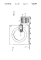
- FIG. 9 shows an enlarged view of a collimator mounted on the scintillation camera detector and the solenoid release mechanism.
- the medical diagnostic nuclear camera mechanical positioner (10) has a track (11) which provides an elongated linear path (12) along which a main frame unit (13) can travel.
- the main frame unit (13) rotatably supports a cylindrical shell drum (14).
- the drum (14) has an axis (15) which is horizontal and perpendicular to the path (12).
- Mounting means (16) support a camera (17) and are connected to one end of the drum (14) and are able to rotate the camera about an axis parallel to axis (15) of drum (14).
- camera (17) may be rotated about axis (15), may be moved linearly along path (12), and the mounting means (16) may rotate the camera (17) about an axis parallel to axis (15) and about an axis perpendicular to axis (15) and parallel with an aperture surface (18) of camera (17) (as shown in FIG. 2).
- the heavy camera (17) is cantilevered only a short distance from its support on drum (14) and all basic linear and rotational movements can be provided with ease of control and a simplified structure.
- main frame unit (13) is provided with a number of trucks (19) which roll along the track (11) for linear movement along path (12).
- Drum (14) is supported by rollers (20) at the bottom and top in order to allow drum (14) to rotate within frame (13).
- the trucks (19) preferably comprise V-wheels such as those available from Bishop-Wisecarver of Pittsburg, Calif.
- the surface of the rails of track (11) is made preferably of hardened steel, and the track (11) can be mounted on either adjustable pads or bolts set into the floor.
- a counterweight (21) is provided diametrically opposite the support member (22) of mounting means (16) and provides a sufficient counterbalance so as to place the center of gravity of drum (14) containing mounting means (16) and camera (17) close to the center of track (11) when camera (17) supports an average weight collimator (23).
- Drum (14) is rotated by drum drive means (24).
- the supporting member (22) is rotated by a motor (25) connected to a gearreduction box (26).
- drum (14) includes a cylindrical shell body (27) on which three annular disks (28), (29) and (30) are mounted.
- a first one (28) of the disks is located on the camera side, a second one (30) of the disks is mounted on the counterweight side and a third one (29) of the disks is mounted centrally on body (27).
- the cylindrical support member (22) is rotatably mounted on disks (28) and (29) and the drum drive means (24) are provided to engage the drum between disks (29) and (30).
- the drum drive means (24) include a motor with gear-reducing box (31) which drive a pulley (32) and a belt or belts (33) for engaging a specially adapted surface of body (27).
- the frame drive means (34) include a motor (35) connected to a gear-reduction box (36) for driving a pulley (37) which is in working engagement with a timing belt (38) for being able to provide a precise linear movement along path (12).
- FIGS. 2 and 7 it is shown how the mechanical positioner (10) can be used to place nuclear camera (17) in line with collimator storage stand (39) which has a plurality (six shown in FIG. 2) of collimator holders (40) vertically disposed one above the other for holding a plurality of collimators (23) and a precalibrated radioactive source (41) having a form similar to the collimators (23).
- Camera (17) has an aperture surface (18) over which collimator (23) is to be placed.
- Camera (17) can be adjusted in height by rotating drum (14) and support member (22) in order to bring surface (18) in line with holder (40).
- the stand (39) is located in front of camera (17).
- the camera aperture surface (18) is provided with means (41) for receiving and fastening a collimator (23) in front of surface (18).
- the collimators (23) are provided with tongues made of UHM plastic which slide along grooves also made of UHM plastic of holders (40) and onto grooves (42) made of UHM plastic of means (41).
- Holders (40) are each provided with two grooves (43), one on each side, which correspond with a pair of grooves (42) of the means (41) provided on camera (17).
- grooves (42) and (43) are brought into accurate alignment so that the tongues of the collimator can slide in the grooves (42), (43) with ease between the camera (17) and the stand (39).
- FIG. 8 shows a cross section of the collimator drive means which comprise feed screw means (44) for each collimator holder (40).
- the feed screw means (44) include a feed screw shaft (45), a smooth shaft (47) parallel to the feed screw shaft (45), a locking member (46) for hooking into collimator (23).
- Nut member (48) has threads for engaging the feed screw shaft (45) and has a slide for engaging the smooth shaft.
- the locking member (46) is pivotally attached to the nut member and is resiliently biased in the vertical direction.
- the nut member (48) may be moved along the feed screw shaft and the smooth shaft by rotation of the feed screw shaft (45) by means of motor (49).
- the locking member (46) is forked and has two prongs for engaging complementary receiving notches (50) of collimator (23). Ends (51) of member (46) may only engage notches (50) when the solenoid release mechanism shown in FIG. 9 is activated.
- FIG. 9 there is shown an end view of camera (17).
- Collimator (23) is slidable in slots or grooves (42) and (43) by tongues (52).
- the collimator locking rods (53) are maintained in a secure position in collimator locking notches (50) by springs (54) and may only be retracted by energizing solenoids (55).
- the solenoids (55) are fixed to a front end of camera (17).
- the collimator (23) has guide slots (56) for guiding the spring biased retracting members (46). Thus, members (46) cannot engage collimator (23) unless solenoids (55) are activated and locking rods (53) are moved out of notches (50) allowing ends (51) to enter notches (50).
Abstract
Description
Claims (14)
Priority Applications (5)
| Application Number | Priority Date | Filing Date | Title |
|---|---|---|---|
| US07/712,352 US5146094A (en) | 1991-06-07 | 1991-06-07 | Medical diagnostic nuclear camera system |
| AU17603/92A AU1760392A (en) | 1991-06-07 | 1992-05-28 | Medical diagnostic nuclear camera system |
| PCT/CA1992/000222 WO1992022246A2 (en) | 1991-06-07 | 1992-05-28 | Medical diagnostic nuclear camera system |
| IL102081A IL102081A0 (en) | 1991-06-07 | 1992-06-02 | Medical diagnostic nuclear camera system |
| ZA924078A ZA924078B (en) | 1991-06-07 | 1992-06-04 | Medical diagnostic nuclear camera system |
Applications Claiming Priority (1)
| Application Number | Priority Date | Filing Date | Title |
|---|---|---|---|
| US07/712,352 US5146094A (en) | 1991-06-07 | 1991-06-07 | Medical diagnostic nuclear camera system |
Publications (1)
| Publication Number | Publication Date |
|---|---|
| US5146094A true US5146094A (en) | 1992-09-08 |
Family
ID=24861755
Family Applications (1)
| Application Number | Title | Priority Date | Filing Date |
|---|---|---|---|
| US07/712,352 Expired - Fee Related US5146094A (en) | 1991-06-07 | 1991-06-07 | Medical diagnostic nuclear camera system |
Country Status (5)
| Country | Link |
|---|---|
| US (1) | US5146094A (en) |
| AU (1) | AU1760392A (en) |
| IL (1) | IL102081A0 (en) |
| WO (1) | WO1992022246A2 (en) |
| ZA (1) | ZA924078B (en) |
Cited By (15)
| Publication number | Priority date | Publication date | Assignee | Title |
|---|---|---|---|---|
| US5262648A (en) * | 1993-02-10 | 1993-11-16 | Independent Scintillation Imaging Systems (Isis) Inc. | Medical diagnostic nuclear camera fork mounting with offset |
| US5278416A (en) * | 1991-06-07 | 1994-01-11 | Sopha Medical | Tomographic gamma camera provided with a swivelling detector |
| US5519223A (en) * | 1994-03-03 | 1996-05-21 | Adac Laboratories, Inc. | Apparatus and method for automated collimator exchange |
| US6044504A (en) * | 1997-08-01 | 2000-04-04 | Is2 Research, Inc. | Patient support for a scintillation camera |
| US6590214B1 (en) | 1999-01-26 | 2003-07-08 | Koninklijke Philips Electronics N.V. | Collimator exchange system |
| WO2004002315A2 (en) * | 2002-06-26 | 2004-01-08 | Sopha Medical Vision International | Method for changing the sighting devices of isotope scanning sensors |
| US20100193698A1 (en) * | 2005-05-16 | 2010-08-05 | Koninklijke Philips Electronics N. V. | Gantry mounted patient table and exchanger for medical imaging |
| US20110228910A1 (en) * | 2010-03-19 | 2011-09-22 | Gregerson Eugene A | Diagnostic imaging apparatus with airflow cooling system |
| US9125613B2 (en) | 2012-06-12 | 2015-09-08 | Mobius Imaging, Llc | Detector system for imaging device |
| US20170135652A1 (en) * | 2014-07-22 | 2017-05-18 | Carestream Health, Inc. | Extremity imaging apparatus for cone beam computed tomography |
| WO2020149743A1 (en) * | 2019-01-17 | 2020-07-23 | Milabs B.V. | Multimodal imaging system and method |
| US10799194B2 (en) | 2010-03-12 | 2020-10-13 | Mobius Imaging, Llc | Caster system for mobile apparatus |
| US10835190B2 (en) | 2013-03-15 | 2020-11-17 | Mobius Imaging, Llc | Mobile X-ray imaging system |
| CN115607174A (en) * | 2022-10-28 | 2023-01-17 | 京心禾(北京)医疗科技有限公司 | Independent collimating device and imaging equipment |
| US11944469B2 (en) | 2010-03-12 | 2024-04-02 | Mobius Imaging Llc | Caster system for mobile apparatus |
Citations (29)
| Publication number | Priority date | Publication date | Assignee | Title |
|---|---|---|---|---|
| US3624398A (en) * | 1969-09-25 | 1971-11-30 | Weldon D Arndt | Serial radiograph table |
| US3982133A (en) * | 1972-11-15 | 1976-09-21 | G. D. Searle & Co. | Collimator changer for scintillation camera |
| US4088889A (en) * | 1977-03-23 | 1978-05-09 | Detroit Osteopathic Hospital Corp. | X-ray film guide |
| US4109155A (en) * | 1973-01-16 | 1978-08-22 | Siemens Aktiengesellschaft | Gamma camera |
| US4129784A (en) * | 1974-06-14 | 1978-12-12 | Siemens Aktiengesellschaft | Gamma camera |
| US4220861A (en) * | 1977-06-15 | 1980-09-02 | SELO Societa Electtronica Lombarda S.p.A. | Gamma camera tomography apparatus |
| US4221971A (en) * | 1979-01-15 | 1980-09-09 | William Burger | Protective shield device |
| US4241254A (en) * | 1976-12-10 | 1980-12-23 | Syntex (U.S.A.) Inc. | X-Ray source moving mechanism suitable for panoramic radiography |
| US4365342A (en) * | 1975-09-26 | 1982-12-21 | Picker International, Inc. | X-Ray film changer for the serial radiography |
| JPS5830685A (en) * | 1981-08-19 | 1983-02-23 | Toshiba Corp | Multi-purpose gamma camera |
| US4445035A (en) * | 1980-08-28 | 1984-04-24 | Tokyo Shibaura Denki Kabushiki Kaisha | Emission computed tomography having radial position control of radiation detector |
| US4459485A (en) * | 1981-05-29 | 1984-07-10 | U.S. Philips Corporation | Gamma tomography apparatus comprising a parallelogram suspension system |
| US4460832A (en) * | 1981-06-15 | 1984-07-17 | Bigham Keith E | Attenuator for providing a test image from a radiation source |
| JPS59178382A (en) * | 1983-03-29 | 1984-10-09 | Hitachi Medical Corp | Emission ct scanning by scintillation camera |
| US4517460A (en) * | 1981-06-24 | 1985-05-14 | U.S. Philips Corporation | Method of calibrating a gamma camera, and a gamma camera including a calibration device |
| US4541108A (en) * | 1984-01-30 | 1985-09-10 | John K. Grady | X-Ray apparatus with tilting table |
| US4645933A (en) * | 1983-07-29 | 1987-02-24 | Picker International, Inc. | Emissive computed tomography |
| US4649277A (en) * | 1983-10-27 | 1987-03-10 | S.E.L.O. Societa Elettronica Lombarda S.P.A. | Multipurpose apparatus for normal or tomographic investigations by means of a gamma camera |
| US4652759A (en) * | 1984-07-13 | 1987-03-24 | Siemens Gammasonics, Inc. | Counterbalanced radiation detection system |
| US4692625A (en) * | 1985-06-24 | 1987-09-08 | Siemens Gammasonics, Inc. | Detector head mounting mechanism and supporting structure |
| US4694481A (en) * | 1985-08-15 | 1987-09-15 | New England Institute Of Comparative Medicine | Transportable X-ray apparatus |
| US4716581A (en) * | 1984-04-09 | 1987-12-29 | Siemens Aktiengesellschaft | X-ray examination apparatus |
| JPS6390787A (en) * | 1986-10-03 | 1988-04-21 | Hitachi Medical Corp | Single photon ect scanner |
| US4741015A (en) * | 1986-12-05 | 1988-04-26 | B. C. Medical Compagnie Limitee | Universal X-ray unit |
| US4758726A (en) * | 1985-03-15 | 1988-07-19 | U.S. Philips Corporation | Collimator exchanging system |
| US4774411A (en) * | 1986-11-07 | 1988-09-27 | U.S. Philips Corporation | Gamma tomography apparatus |
| US4774412A (en) * | 1985-12-03 | 1988-09-27 | Kabushiki Kaisha Toshiba | Scintillation camera system |
| US4809313A (en) * | 1986-03-12 | 1989-02-28 | Minnesota Mining And Manufacturing Company | X-ray film feeding magazine usable in film handling automatic apparatus |
| JPH02263185A (en) * | 1989-04-04 | 1990-10-25 | Toshiba Corp | Collimator change device of radiation detector for nuclear medical diagnostic device |
Family Cites Families (4)
| Publication number | Priority date | Publication date | Assignee | Title |
|---|---|---|---|---|
| US4669105A (en) * | 1984-05-29 | 1987-05-26 | Aaron Fenster | System for quantitative arteriography |
| JPH0619449B2 (en) * | 1989-04-04 | 1994-03-16 | 株式会社東芝 | Scintillation camera |
| JPH0462492A (en) * | 1990-06-29 | 1992-02-27 | Toshiba Corp | Nuclear medical diagnostic device |
| US5075554A (en) * | 1990-09-27 | 1991-12-24 | Siemens Gammasonics, Inc. | Scintillation camera gantry supporting a plurality of detector heads between two parallel plates |
-
1991
- 1991-06-07 US US07/712,352 patent/US5146094A/en not_active Expired - Fee Related
-
1992
- 1992-05-28 WO PCT/CA1992/000222 patent/WO1992022246A2/en active Application Filing
- 1992-05-28 AU AU17603/92A patent/AU1760392A/en not_active Abandoned
- 1992-06-02 IL IL102081A patent/IL102081A0/en unknown
- 1992-06-04 ZA ZA924078A patent/ZA924078B/en unknown
Patent Citations (29)
| Publication number | Priority date | Publication date | Assignee | Title |
|---|---|---|---|---|
| US3624398A (en) * | 1969-09-25 | 1971-11-30 | Weldon D Arndt | Serial radiograph table |
| US3982133A (en) * | 1972-11-15 | 1976-09-21 | G. D. Searle & Co. | Collimator changer for scintillation camera |
| US4109155A (en) * | 1973-01-16 | 1978-08-22 | Siemens Aktiengesellschaft | Gamma camera |
| US4129784A (en) * | 1974-06-14 | 1978-12-12 | Siemens Aktiengesellschaft | Gamma camera |
| US4365342A (en) * | 1975-09-26 | 1982-12-21 | Picker International, Inc. | X-Ray film changer for the serial radiography |
| US4241254A (en) * | 1976-12-10 | 1980-12-23 | Syntex (U.S.A.) Inc. | X-Ray source moving mechanism suitable for panoramic radiography |
| US4088889A (en) * | 1977-03-23 | 1978-05-09 | Detroit Osteopathic Hospital Corp. | X-ray film guide |
| US4220861A (en) * | 1977-06-15 | 1980-09-02 | SELO Societa Electtronica Lombarda S.p.A. | Gamma camera tomography apparatus |
| US4221971A (en) * | 1979-01-15 | 1980-09-09 | William Burger | Protective shield device |
| US4445035A (en) * | 1980-08-28 | 1984-04-24 | Tokyo Shibaura Denki Kabushiki Kaisha | Emission computed tomography having radial position control of radiation detector |
| US4459485A (en) * | 1981-05-29 | 1984-07-10 | U.S. Philips Corporation | Gamma tomography apparatus comprising a parallelogram suspension system |
| US4460832A (en) * | 1981-06-15 | 1984-07-17 | Bigham Keith E | Attenuator for providing a test image from a radiation source |
| US4517460A (en) * | 1981-06-24 | 1985-05-14 | U.S. Philips Corporation | Method of calibrating a gamma camera, and a gamma camera including a calibration device |
| JPS5830685A (en) * | 1981-08-19 | 1983-02-23 | Toshiba Corp | Multi-purpose gamma camera |
| JPS59178382A (en) * | 1983-03-29 | 1984-10-09 | Hitachi Medical Corp | Emission ct scanning by scintillation camera |
| US4645933A (en) * | 1983-07-29 | 1987-02-24 | Picker International, Inc. | Emissive computed tomography |
| US4649277A (en) * | 1983-10-27 | 1987-03-10 | S.E.L.O. Societa Elettronica Lombarda S.P.A. | Multipurpose apparatus for normal or tomographic investigations by means of a gamma camera |
| US4541108A (en) * | 1984-01-30 | 1985-09-10 | John K. Grady | X-Ray apparatus with tilting table |
| US4716581A (en) * | 1984-04-09 | 1987-12-29 | Siemens Aktiengesellschaft | X-ray examination apparatus |
| US4652759A (en) * | 1984-07-13 | 1987-03-24 | Siemens Gammasonics, Inc. | Counterbalanced radiation detection system |
| US4758726A (en) * | 1985-03-15 | 1988-07-19 | U.S. Philips Corporation | Collimator exchanging system |
| US4692625A (en) * | 1985-06-24 | 1987-09-08 | Siemens Gammasonics, Inc. | Detector head mounting mechanism and supporting structure |
| US4694481A (en) * | 1985-08-15 | 1987-09-15 | New England Institute Of Comparative Medicine | Transportable X-ray apparatus |
| US4774412A (en) * | 1985-12-03 | 1988-09-27 | Kabushiki Kaisha Toshiba | Scintillation camera system |
| US4809313A (en) * | 1986-03-12 | 1989-02-28 | Minnesota Mining And Manufacturing Company | X-ray film feeding magazine usable in film handling automatic apparatus |
| JPS6390787A (en) * | 1986-10-03 | 1988-04-21 | Hitachi Medical Corp | Single photon ect scanner |
| US4774411A (en) * | 1986-11-07 | 1988-09-27 | U.S. Philips Corporation | Gamma tomography apparatus |
| US4741015A (en) * | 1986-12-05 | 1988-04-26 | B. C. Medical Compagnie Limitee | Universal X-ray unit |
| JPH02263185A (en) * | 1989-04-04 | 1990-10-25 | Toshiba Corp | Collimator change device of radiation detector for nuclear medical diagnostic device |
Cited By (26)
| Publication number | Priority date | Publication date | Assignee | Title |
|---|---|---|---|---|
| US5278416A (en) * | 1991-06-07 | 1994-01-11 | Sopha Medical | Tomographic gamma camera provided with a swivelling detector |
| US5262648A (en) * | 1993-02-10 | 1993-11-16 | Independent Scintillation Imaging Systems (Isis) Inc. | Medical diagnostic nuclear camera fork mounting with offset |
| US5519223A (en) * | 1994-03-03 | 1996-05-21 | Adac Laboratories, Inc. | Apparatus and method for automated collimator exchange |
| US6044504A (en) * | 1997-08-01 | 2000-04-04 | Is2 Research, Inc. | Patient support for a scintillation camera |
| US6255656B1 (en) | 1997-08-01 | 2001-07-03 | Is2 Research Inc. | Positioner for a scintillation camera detector head |
| US6288398B1 (en) | 1997-08-01 | 2001-09-11 | Is2 Research Inc. | Support structure for medical diagnostic equipment |
| US6590214B1 (en) | 1999-01-26 | 2003-07-08 | Koninklijke Philips Electronics N.V. | Collimator exchange system |
| WO2004002315A2 (en) * | 2002-06-26 | 2004-01-08 | Sopha Medical Vision International | Method for changing the sighting devices of isotope scanning sensors |
| WO2004002315A3 (en) * | 2002-06-26 | 2004-03-18 | Sopha Medical Vision Internat | Method for changing the sighting devices of isotope scanning sensors |
| US20100193698A1 (en) * | 2005-05-16 | 2010-08-05 | Koninklijke Philips Electronics N. V. | Gantry mounted patient table and exchanger for medical imaging |
| US9462984B2 (en) | 2009-10-09 | 2016-10-11 | Mobius Imaging, Llc | Diagnostic imaging apparatus with airflow cooling system |
| US11944469B2 (en) | 2010-03-12 | 2024-04-02 | Mobius Imaging Llc | Caster system for mobile apparatus |
| US10799194B2 (en) | 2010-03-12 | 2020-10-13 | Mobius Imaging, Llc | Caster system for mobile apparatus |
| US8770839B2 (en) | 2010-03-19 | 2014-07-08 | Mobius Imaging, Llc | Diagnostic imaging apparatus with airflow cooling system |
| WO2011115711A1 (en) * | 2010-03-19 | 2011-09-22 | Mobius Imaging, Llp | Diagnostic imaging apparatus with airflow cooling system |
| US20110228910A1 (en) * | 2010-03-19 | 2011-09-22 | Gregerson Eugene A | Diagnostic imaging apparatus with airflow cooling system |
| US9125613B2 (en) | 2012-06-12 | 2015-09-08 | Mobius Imaging, Llc | Detector system for imaging device |
| US10835190B2 (en) | 2013-03-15 | 2020-11-17 | Mobius Imaging, Llc | Mobile X-ray imaging system |
| US10874359B2 (en) | 2013-03-15 | 2020-12-29 | Mobius Imaging, Llc | Caster system for mobile apparatus |
| US11957493B2 (en) | 2013-03-15 | 2024-04-16 | Mobius Imaging, Llc | Mobile X-ray imaging system |
| US20170135652A1 (en) * | 2014-07-22 | 2017-05-18 | Carestream Health, Inc. | Extremity imaging apparatus for cone beam computed tomography |
| US10548540B2 (en) * | 2014-07-22 | 2020-02-04 | Carestream Health, Inc. | Extremity imaging apparatus for cone beam computed tomography |
| WO2020149743A1 (en) * | 2019-01-17 | 2020-07-23 | Milabs B.V. | Multimodal imaging system and method |
| NL2022409B1 (en) * | 2019-01-17 | 2020-08-18 | Milabs Bv | Multimodal imaging system |
| CN115607174A (en) * | 2022-10-28 | 2023-01-17 | 京心禾(北京)医疗科技有限公司 | Independent collimating device and imaging equipment |
| CN115607174B (en) * | 2022-10-28 | 2023-10-10 | 中核粒子医疗科技有限公司 | Independent collimation device and imaging equipment |
Also Published As
| Publication number | Publication date |
|---|---|
| WO1992022246A2 (en) | 1992-12-23 |
| IL102081A0 (en) | 1993-01-14 |
| AU1760392A (en) | 1993-01-12 |
| WO1992022246A3 (en) | 1993-04-01 |
| ZA924078B (en) | 1993-02-24 |
Similar Documents
| Publication | Publication Date | Title |
|---|---|---|
| US5146094A (en) | Medical diagnostic nuclear camera system | |
| US6288398B1 (en) | Support structure for medical diagnostic equipment | |
| US4426578A (en) | Support structure for rotatable scintillation detector | |
| US4475072A (en) | Patient-positioning X-ray table | |
| US4645933A (en) | Emissive computed tomography | |
| US4651007A (en) | Medical diagnostic mechanical positioner | |
| US6184530B1 (en) | Adjustable dual-detector image data acquisition system | |
| US5210422A (en) | Scintillation camera | |
| US5097132A (en) | Nuclear medicine camera system with improved gantry and patient table | |
| CN1140403A (en) | Stabilized, cantilevered, patient trauma table system | |
| JP2005527800A (en) | System and method for imaging large field objects | |
| US3852601A (en) | Scanning device for scintigraphy according to three orthogonal planes | |
| EP0391259B1 (en) | Scintillation camera | |
| EP0511379B1 (en) | Nuclear medicine camera gantry system with vertically stored collimators | |
| EP0453736A1 (en) | Scintillation camera with automatically counterbalanced gantry | |
| CN101175441A (en) | A gantry mounted patient table and exchanger for medical imaging | |
| JPS63133077A (en) | Gamma tomographic device | |
| US6590214B1 (en) | Collimator exchange system | |
| US5093575A (en) | Dual rotatable head gamma camera | |
| JP3122821B2 (en) | Gantry device for nuclear medicine cameras with vertical storage collimator | |
| US5325413A (en) | X-ray examination apparatus | |
| US3244883A (en) | X-ray tubestand | |
| USRE37474E1 (en) | Adjustable dual-detector image data acquisition system | |
| US6949747B2 (en) | Apparatus and method for automatically adjusting the path of a medical camera | |
| JP4409865B2 (en) | Nuclear medicine diagnostic equipment |
Legal Events
| Date | Code | Title | Description |
|---|---|---|---|
| AS | Assignment |
Owner name: ISIS INC., CANADA Free format text: ASSIGNMENT OF ASSIGNORS INTEREST.;ASSIGNOR:STARK, IAIN E.;REEL/FRAME:005744/0969 Effective date: 19910606 |
|
| AS | Assignment |
Owner name: INDEPENDENT SCINTILLATION IMAGING SYSTEMS (ISIS) I Free format text: ASSIGNMENT OF ASSIGNORS INTEREST.;ASSIGNOR:STARK, IAIN E.;REEL/FRAME:006159/0730 Effective date: 19920505 |
|
| FPAY | Fee payment |
Year of fee payment: 4 |
|
| AS | Assignment |
Owner name: PARK MEDICAL SYSTEMS INC., CANADA Free format text: CHANGE OF NAME;ASSIGNOR:INDEPENDENCE SCINTILLATION IMAGING SYSTEMS (ISIS) INC.;REEL/FRAME:007846/0065 Effective date: 19940407 |
|
| AS | Assignment |
Owner name: MIDWEST NUCLEAR, INC., OHIO Free format text: ASSIGNMENT OF ASSIGNORS INTEREST;ASSIGNOR:CARON BELANGER ERNST & YOUNG, INC., TRUSTEE TO THE BANKRUPTCY ESTATE OF PARK MEDICAL SYSTEMS, INC.;REEL/FRAME:009662/0580 Effective date: 19980904 |
|
| FEPP | Fee payment procedure |
Free format text: PAYOR NUMBER ASSIGNED (ORIGINAL EVENT CODE: ASPN); ENTITY STATUS OF PATENT OWNER: SMALL ENTITY |
|
| REMI | Maintenance fee reminder mailed | ||
| FPAY | Fee payment |
Year of fee payment: 8 |
|
| SULP | Surcharge for late payment | ||
| REMI | Maintenance fee reminder mailed | ||
| LAPS | Lapse for failure to pay maintenance fees | ||
| FP | Lapsed due to failure to pay maintenance fee |
Effective date: 20040908 |
|
| AS | Assignment |
Owner name: TAASCO, L.L.C., IOWA Free format text: ASSIGNMENT OF ASSIGNORS INTEREST;ASSIGNOR:MIDWEST NUCLEAR, INC.;REEL/FRAME:020174/0232 Effective date: 20051022 |
|
| AS | Assignment |
Owner name: VERISTA IMAGING, INC., IOWA Free format text: ASSIGNMENT OF ASSIGNORS INTEREST;ASSIGNOR:TAASCO, L.L.C.;REEL/FRAME:020417/0443 Effective date: 20080123 |
|
| STCH | Information on status: patent discontinuation |
Free format text: PATENT EXPIRED DUE TO NONPAYMENT OF MAINTENANCE FEES UNDER 37 CFR 1.362 |