US5090297A - All-elastomer fluid-pressure-actuatable twistors and twistor drive assemblies - Google Patents
All-elastomer fluid-pressure-actuatable twistors and twistor drive assemblies Download PDFInfo
- Publication number
- US5090297A US5090297A US07/521,232 US52123290A US5090297A US 5090297 A US5090297 A US 5090297A US 52123290 A US52123290 A US 52123290A US 5090297 A US5090297 A US 5090297A
- Authority
- US
- United States
- Prior art keywords
- twistor
- twistors
- drive gear
- fluid
- drive
- Prior art date
- Legal status (The legal status is an assumption and is not a legal conclusion. Google has not performed a legal analysis and makes no representation as to the accuracy of the status listed.)
- Expired - Fee Related
Links
Images


Classifications
-
- F—MECHANICAL ENGINEERING; LIGHTING; HEATING; WEAPONS; BLASTING
- F04—POSITIVE - DISPLACEMENT MACHINES FOR LIQUIDS; PUMPS FOR LIQUIDS OR ELASTIC FLUIDS
- F04B—POSITIVE-DISPLACEMENT MACHINES FOR LIQUIDS; PUMPS
- F04B43/00—Machines, pumps, or pumping installations having flexible working members
- F04B43/08—Machines, pumps, or pumping installations having flexible working members having tubular flexible members
- F04B43/084—Machines, pumps, or pumping installations having flexible working members having tubular flexible members the tubular member being deformed by stretching or distortion
-
- F—MECHANICAL ENGINEERING; LIGHTING; HEATING; WEAPONS; BLASTING
- F01—MACHINES OR ENGINES IN GENERAL; ENGINE PLANTS IN GENERAL; STEAM ENGINES
- F01B—MACHINES OR ENGINES, IN GENERAL OR OF POSITIVE-DISPLACEMENT TYPE, e.g. STEAM ENGINES
- F01B19/00—Positive-displacement machines or engines of flexible-wall type
- F01B19/04—Positive-displacement machines or engines of flexible-wall type with tubular flexible members
-
- F—MECHANICAL ENGINEERING; LIGHTING; HEATING; WEAPONS; BLASTING
- F15—FLUID-PRESSURE ACTUATORS; HYDRAULICS OR PNEUMATICS IN GENERAL
- F15B—SYSTEMS ACTING BY MEANS OF FLUIDS IN GENERAL; FLUID-PRESSURE ACTUATORS, e.g. SERVOMOTORS; DETAILS OF FLUID-PRESSURE SYSTEMS, NOT OTHERWISE PROVIDED FOR
- F15B15/00—Fluid-actuated devices for displacing a member from one position to another; Gearing associated therewith
- F15B15/08—Characterised by the construction of the motor unit
- F15B15/10—Characterised by the construction of the motor unit the motor being of diaphragm type
- F15B15/103—Characterised by the construction of the motor unit the motor being of diaphragm type using inflatable bodies that contract when fluid pressure is applied, e.g. pneumatic artificial muscles or McKibben-type actuators
Definitions
- the present invention is in the field of fluid-pressure actuators and more particularly relates to all-elastomer fluid-pressure-actuatable twistors each advantageously moldable or formable from resilient elastomeric material and especially adapted to be used in opposed pairs pre-twisted in opposite senses and geared to a common output shaft to produce rotation of the shaft in opposite directions in a twistor drive assembly. Feeding fluid under various and different controlled pressures into the opposed pairs of twistors causes the common output shaft to be rotated smoothly into various predeterminable angular positions in an open-loop control system. By cyclically reversing the shaft rotation, a continuous fluid motor results upon attaching a sprag to the shaft.
- this network of inextensible strands was bonded or attached to the outside surface of the bladder.
- Yarlott U.S. Pat. No. 3,645,173 and Paynter U.S. Pat. Nos. 4,108,050, 4,751,868 and 4,751,869 disclosed relatively inextensible strands bonded to the exterior surface of the bladder.
- Kukolj in FIG. 16 showed a network of non-stretchable flexible elements, such as braided wire, embedded within the elastomeric material from which the wall of the bladder was made.
- All-elastomer fluid-pressure-actuatable twistors include a tubular wall and interior webs of various configurations which reinforce the tubular wall so as to prevent ballooning and which reduce the "dead volume" of the chamber surrounded by the tubular wall so as to reduce fluid demand.
- the tubular wall includes first and second mounting means at its respective ends.
- these interior webs are imperforate partitions joined together along a twist axis of the twistor and joined to the tubular wall, thereby separating the chamber into multiple compartments extending longitudinally along the twistor. These interior compartments are accessible for inflation by pressurized fluid fed into the compartments through at least on end of the twistor.
- the twistor By applying torque to the first mounting means in one sense around the twist axis relative to the second mounting means, the twistor becomes twisted around its twist axis into a generally helically twisted configuration.
- the twistor By feeding fluid under pressure into the compartments, the twistor is caused to untwist, thereby overcoming the applied torque for turning the first mounting means around the twist axis in the other sense to provide useful, smooth turning motion.
- the twistors as described are each advantageously moldable or formable from tough, resilient, elastomeric material such as polyurethane as a monolithic all-elastomer unit.
- the first and second mounting means are shown in some embodiments as comprising first and second rims encircling the twist axis at opposite ends of the twistor. These rims are also integrally moldable with the respective ends of the tubular wall.
- Splined mounting end lugs with encircling O-ring seals on the ends of twistors can be slid into support sockets for quick and convenient installation into twistor drive assemblies.
- pairs of these twistors are pre-twisted in opposite senses and are geared to a common output shaft for acting as opposed pairs in a twistor drive assembly capable of turning the shaft in either direction.
- the common output shaft is turned into predetermined angular positions by controlling the respective pressure levels of fluid being supplied into the opposed pairs of twistors in an advantageous open-loop control system which uniquely offers simple direct manipulation of output shaft position and effective stiffness.
- twistor drive assemblies ar especially adapted for stacking in an end-to-end relationship in an axially extended stacked array having a common output shaft extending through the entire stacked array.
- the turning moments of these stacked twistor drive subassemblies in the array are added together in jointly turning the common output shaft in either direction.
- twistor drive assemblies are designed to accommodate various gear ratios between the pairs of opposed twistors and their common output shaft, thereby providing great flexibility for use in various applications, some of which may require a greater range of angular travel of the common output shaft and others of which may require greater turning moment with less angular travel of the common output shaft. Moreover, multiple twistor drive assemblies can be stacked together in an end-to-end array in applications where greater output turning moments are desired.
- a continuous, reversible, nutating motor is provided upon attaching a sprag drive to the output shaft.
- twistors By virtue of their all-elastomer construction, the various configurations of these twistors as disclosed are less expensive to fabricate than prior twistor actuators and they offer promise of longer operating lives than prior pressurized-fluid-driven actuators having composite structures incorporating relatively inextensible or non-stretchable flexible reinforcing strands which caused deleterious stress-concentrations and/or abrasions of the strands and in the bladder wall.
- the twistor body (which comprises a tubular wall having internal elements integral with the tubular wall, for example, such as webs, ribs, flanges, fillets or partitions) is formed by extruding.
- the end mounting means can comprise two separate end fittings, which are attached to the opposite ends of the twistor body with an air-tight attachment.
- the twistor body can be relatively elongated for providing a plurality of twistors in series in end-to-end relationship, thereby comprising a "twistor string”.
- each twistor in the twistor string can readily supply 60 degrees of rotation
- the "N" twistors in a twistor string can readily supply N ⁇ 60 degrees of rotation, which can then be geared down, if desired, to increase torque output.
- Such a gearing down can be obtained by bevel gearing or by a worm-gear drive or by spur gearing.
- the twistor string can be arranged to extend longitudinally along a strut serving like a bone in an arm or leg of a robot.
- a strut can be a hollow tube with the twistor string extending longitudinally within this tube.
- a worm-gear drive or a bevel-gear drive is used in association with a pivoted joint or articulation for moving a second strut, which is swingably joined to the strut containing the twistor string.
- end fittings are shown and various attachments between these end fittings and an extruded twistor body are described.
- the end fitting can be arranged to mount within a socket in a keyed engaged relationship with the socket for preventing rotation of the end fitting relative to its socket.
- a keyed engaged relationship is provided by a hexagonal or splined shape or other non-circular shape of the mounting portion of the end fitting.
- the end fitting can have a tailored shape for acting as an output device for imparting motion or torque, for example, an end fitting is shown with a rim having spur gear teeth.
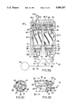
- FIG. 1 is a longitudinal sectional view of an all-elastomer twistor embodying the present invention. This sectional view in FIG. 1 is taken along the line 1--1 in FIG. 2, which is slightly offset to the left of the twistor axis for more clearly showing the reinforcing web-partition structure.
- the two end fittings are shown as flanges on opposite ends of the tubular elastomer twistor body and being integral with the twistor body.
- FIG. 1A is a longitudinal sectional view similar to FIG. 1, except that FIG. 1A shows that the twistor body can be an elongated extruded elastomer tube having internal webs integral with the tubular wall. These internal webs are internally joined along the axis of the twistor body forming partitions dividing the interior of the twistor into multiple longitudinally-extending sector-shaped compartments. The two end fittings are separate pieces which are clamped air-tight to opposite ends of the twistor body.
- FIG. 1B is an end elevation of the twistor of FIG. 1A, as seen from the position 1B--1B, showing a hexagonal shape of a flange on an end fitting.
- FIG. 1C is an end elevation of the other end of the twistor of FIG. 1A, as seen from the position 1C--1C, showing a circular shape of a flange on an end fitting.
- FIG. 1D is an enlarged perspective view of an end fitting, and FIG. 1D includes a fragmentary perspective view for showing a flange on an end fitting provided with spur gear teeth, and also a stub shaft as shown in dashed outline may project axially from this spur gear.
- FIG. 1E is a longitudinal sectional view similar to FIG. 1A showing that the end fittings are bonded to the twistor body, for example, by adhesive.
- FIG. 2 is an end elevational view of the twistor of FIG. 1 as seen from the end position 2--2 in FIG. 1.
- FIG. 2A is a cross-sectional view of the twistor of FIGS. 1 and 2 and of the twistors of FIGS. 1A and 1E and of FIGS. 8 and 9. This cross-sectional view in FIG. 2A is taken along the plane 2A--2A in FIG. 1 and in FIG. 1A and in FIG. 1E and in FIG. 8 and in FIG. 9.
- FIG. 3 is an elevational sectional view of a twistor drive assembly (herein also called a "twistor pack") showing a pair of oppositely pre-twisted twistors operating as an opposed pair for turning a common output shaft in either direction.
- FIG. 3 is a view taken along the plane 3--3 in FIG. 4.
- FIG. 3A is an elevational sectional view, similar to FIG. 3, for showing an alternative embodiment of the twistor drive assembly (twistor pack).
- the common output shaft seen in FIG. 3 has been removed; and in lieu thereof, an output shaft is directly connected to one of the twistors.
- Hexagonal mounting portions of end fittings fit into hexagonal sockets in the housing for providing a keyed engagement in each socket mount for anchoring the end fittings against rotation.
- FIG. 3B is a partial elevational sectional view of one of the twistors in the twistor drive assembly of FIG. 3A showing the end fitting attached to the twistor body by an encircling clamp.
- FIG. 3C is a cross-sectional view taken along plane 3C--3C in FIG. 3B showing the internal web-partitions within the twistor body and the clamp encircling the tubular wall. Slots in the end fitting receive and engage the web-partitions.
- FIG. 4 is a plan cross-sectional view taken along the plane 4--4 in the twistor drive assembly (twistor pack) of FIG. 3 for showing the gearing arrangement for four twistors operating as two opposed pairs.
- FIG. 4 also indicates the fluid passages for feeding these four twistors operating as two opposed pairs.
- FIG. 5 is a partial elevational sectional view for further showing the fluid feed passages and also for showing a fluid control system for operating the twistor drive assembly of FIGS. 3, 4 and 5 in an open-loop control system.
- FIG. 3A shows an open-loop control system similar to that shown in FIG. 5.
- FIG. 6 shows the convenient manner in which multiple twistor drive assemblies can be stacked in end-to-end array for adding together their turning moments applied to a common output shaft extending through the entire stack.
- FIG. 7 (on Sheet 7) is a partial plan sectional view taken along a plane corresponding to the plane 4--4 in FIG. 3 for showing a different gear ratio from that seen in FIG. 4.
- FIG. 7A shows a gearing arrangement for a six-twistor drive assembly (six-twistor pack).
- FIGS. 8 and 9 are longitudinal sectional views similar to FIGS. 1, 1A and 1E showing other embodiments of twistors in which the reinforcing webs have circular openings or square openings, respectively.
- FIG. 10 is a longitudinal sectional view of a twistor body similar to FIGS. 1, 1A and 1E in which the reinforcing webs have generally triangular cross-sectional shapes as seen in FIG. 10A, which is a cross section taken along the plane 10A--10A in FIG. 10.
- the twistor body shape of FIG. 10A can be formed, for example, by extrusion.
- FIG. 10B is a cross-sectional view of a twistor body formed, for example, by extrusion in which the partitions include fillets contiguous with the tubular wall.
- FIG. 11 is a longitudinal sectional view of a twistor body similar to FIGS. 1, 1E and 10 in which the reinforcing webs have generally rounded shapes as seen in FIG. 11A, a cross section taken along the plane 11A--11A in FIG. 11.
- FIG. 11B is a cross-sectional view of a twistor body formed, for example, by extrusion in which there are eight partitions dividing the interior of the tubular wall into eight sector-shaped compartments.
- FIG. 12 is an elevational view of an all elastomer twistor having an internal configuration corresponding to any one of the twistors previously shown.
- An end mounting of this twistor has a keyed (splined) shape with an encircling O-ring for quick easy mounting in sealed (air-tight) relationship in a conforming socket.
- FIG. 13 is an end elevational view of the twistor of FIG. 12 as seen from the position 13--13 in FIG. 12 and showing further details of the keyed (splined) mounting end.
- FIG. 14 is a sectional view through another embodiment of a twistor drive assembly (twistor pack) in which a pair of twistors are attached to each drive gear on opposite sides in a monolithic twistor-pair drive arrangement.
- Each pair of twistors is helically twisted in the same sense, thus providing both forward (F) and reverse (R) drive torque.
- This drive arrangement utilizes the unique flexural properties of monolithic twistor pairs in an improvement upon the drive arrangement taught in my U.S. Pat. No. 4,751,868. In such and similar arrangements arbitrary gear-ratios are readily obtained (as illustrated in FIGS. 4, 7 and 7A).
- Advantageously, only two shaft bushings or bearings are required for rotatably mounting the common output shaft, regardless of the number of monolithic twistor-pairs employed.
- FIG. 15 is a partial sectional view taken along the plane 15--15 in FIG. 14 showing the gearing engagement and fluid-powered torque action.
- FIG. 16 is a sectional view through another twistor pack in which each drive gear straddles a pair of twistors in a monolithic dual twistor-pair drive arrangement.
- Each pair of twistors is helically twisted in opposite senses.
- the two twistors attached to a gear are operating in parallel aiding relationship, thereby providing twice the forward drive torque (2F) or twice the reverse drive torque (2R) from each such monolithic dual twistor-pair.
- FIG. 17 is a partial sectional view taken along the plane 17--17 in FIG. 16 showing the gearing arrangement and fluid-powered torque action.
- FIG. 18 is a partial sectional view taken along the plane 18--18 in FIG. 19.
- FIG. 18 depicts another gearing arrangement yielding a compact powerful twistor pack in which four forward/reverse (F, R) twistor-pairs are engaged directly with the centrally-located shaft gear, while four more reverse/forward (R, F) twistor-pairs engage only with the adjacent gears of the forward/reverse twistors.
- F, R forward/reverse
- R, F reverse/forward
- eight twistor-pairs are included in this twistor pack.
- FIG. 19 is an elevational sectional view taken along the plane 19--19 in FIG. 18.
- the unique feature of my invention is that the twistor-pairs are intentionally mounted in a bow-legged configuration, as is clearly illustrated in FIG. 19, for holding their output drive gears firmly in engagement with the driven gear on the common output shaft or firmly in engagement with the gear of an adjacent twistor-pair.
- a similar bow-legged twistor-pair mounting arrangement is shown in FIGS. 14 and 16, but FIG. 19 shows this bow-legged arrangement more clearly than in FIGS. 14 and 16.
- FIG. 20 depicts a gearing arrangement similar to FIG. 18, in which four forward drive twistor-pairs (2F) engage directly with the centrally-located shaft gear, and four more reverse drive twistor-pairs (2R) engage only with the adjacent gears of the forward drive twistors.
- Each of these forward drive twistor-pairs (2F) is similar to the forward drive twistor pair shown in FIG. 16, and each of these reverse drive twistor-pairs 2R is similar to the reverse drive twistor-pair shown in FIG. 16.
- FIG. 21 shows a gearing arrangement similar to FIGS. 18 and 20.
- FIG. 21 shows a gearing arrangement similar to FIGS. 18 and 20.
- the relative positions of the four forward drive twistor-pairs (2F) are interchanged with the relative positions of the four reverse drive twistor-pairs (2R).
- FIG. 22 is a disassembled perspective view.
- sheet 11 shows a pair of twistors on opposite sides of their central drive gear.
- Each twistor has a keyed mounting end (hexagonal-shaped end) adapted to be inserted into a conforming socket.
- the central gear is generally ring-shaped and has a hexagonal axial opening for providing clearance to fit over a hexagonal end of the twistor-pair.
- This central gear is captured on a twin-lug central mount and is held in place by a washer-shaped retainer having a hexagonal axial opening for providing clearance to fit over the other hexagonal end of the twistor-pair.
- U-shaped washers and other capturing devices are also possible.
- FIG. 23 (Sheet 9) shows bearing sleeves and a gear mounted on a keyed shaft for ease of assembly.
- FIG. 24 (Sheet 9) is a cross sectional view taken along the plane 24--24 in FIG. 23.
- FIG. 25 (Sheet 12) illustrates a multiple twistor pack drive assembly employed with a reversible sprag (one-way clutch) to achieve a compact and powerful fluid motor providing continuous rotation of an output shaft.
- FIG. 26 (Sheet 13) is an elevational view of a fluid-driven, single-acting jointed strut arrangement suitable for use as an arm in a manipulator or for use as an arm or leg in a robot.
- This pivoted joint is fluid-power-driven in one direction by a twistor string acting through a bevel-gear drive and is moved back in the other direction by a return spring.
- FIG. 27 is an elevational sectional view of the joint arrangement of FIG. 26 showing a twistor string-mounted within a tubular strut for turning one of the bevel gears. All of these twistors in this twistor string drive in the same direction, which may be considered the fluid-driven-powered forward direction, and the return spring may be considered as moving the joint in the reverse direction. Since all of these twistors now drive in the same direction, only one fluid inlet port is used.
- FIG. 28 is an elevational sectional view of a jointed strut arrangement generally similar to FIG. 27, except that the twistor string in FIG. 28 has a central output spur gear with two forward-drive twistors in series on one side of this central gear and two reverse-drive twistors in series on the other side of this central gear; thus, two fluid inlet ports are provided.
- FIG. 28 shows a joint which is fluid-power-driven in either direction, i.e. a double-acting powered joint.
- the central spur gear drives a transfer shaft which operates a worm-gear, thereby providing a powerfully driven joint movement between these pivoted struts.
- FIG. 29 shows a side elevational view of the double-acting fluid-power-driven jointed strut arrangement of FIG. 28. A portion of a strut in FIG. 29 is broken away for showing the twistor string located within the tubular strut.
- FIG. 30 is a perspective view of a twistor drive assembly (twistor pack), wherein the two end pieces of the housing frame are identical, and the top and bottom housing pieces are also identical. These end pieces and top and bottom pieces are adapted to be injection molded of relatively hard plastic.
- FIG. 31 is an enlarged perspective view of one of the end pieces or components of the housing frame seen in FIG. 30.
- FIG. 32 is an enlarged perspective view of a top or a bottom piece (component) of the housing frame seen in FIG. 30. It will be noted that the twistor-pair of FIG. 22 with its hexagonal end mounts will neatly fit and nest into the housing components of FIGS. 32 and 31.
- FIG. 33 sets forth analytical force diagrams and equations for explaining the advantageous action of the bowed (bow-legged) twistor-pair mounting arrangement shown in FIGS. 19, 14 and 16, respectively.
- FIGS. 1, 2 and 2A there is shown a twistor 10 in its initial untwisted condition having a twistor body 18 comprising tubular wall 12 extending between mounting rims 14 and 16 located at opposite ends of the twistor body.
- the twistor 10 has a twist axis 15 extending longitudinally through the twistor body 18 concentric with the tubular wall 12, which is shown as having a circular cylindrical shape.
- the mounting rims 14 and 16 are shown as flanges projecting radially outwardly from opposite ends of the tubular wall 12. It is to be noted that separate end pieces, as shown in FIGS. 1A and 1E, can be mounted on an extruded tubular body 18.
- each of the four compartments 20 Surrounded by the tubular wall 12 is an internal chamber 11 separated into four longitudinally extending compartments 20 by four reinforcing web-partitions 22 joined together at a common junction 24 extending along the twist axis 15. These partitions are also joined to the tubular wall 12 at four junctions 26 uniformly angularly spaced around the twist axis. These web-partitions 22 are imperforate and are shown as being planar; thus each of the four compartments 20 has a sector sectional shape, as seen in FIGS. 2 and 2A.
- the four interior web-partitions 22 together with their common junction 24 have the shape of an equal-arm orthogonal cross as seen in FIGS. 2 and 2A. Since these web-partitions are planar and have a common junction 24 extending along the twist axis, and since the tubular wall 12 is circular cylindrical in shape, it is noted that the four junctions 26 with the tubular wall extend straight and parallel with the twist axis 15, when the twistor body 18 is in its initial untwisted condition as shown in FIGS. 1, 2 and 2A.
- the tubular wall 12 and the web-partitions 22 of the twistor body 18 are integrally formed of resilient, tough, elastomeric material, for example, such as polyurethane.
- This twistor 10, including the tubular wall 12, the interior reinforcing web-partitions 22, and the outwardly projecting mounting rims 14 and 16 can be molded as an integral unit in one molding operation from the same resilient elastomeric material throughout the whole twistor 10.
- the cost of such an integrally molded twistor is greatly reduced as compared with any prior composite fluid-pressure-actuatable torsional actuator (twistor) fabricated or built up from various different materials or reinforced with fiber windings or patterns of strands or filaments or braided, woven or knit sleeves or built-up layers.
- the circular cylindrical tubular wall 12 and the web-partitions 22 of the twistor body 18 are molded in one molding operation from the same elastomeric material, for example, by injection molding or by extrusion with the opposite ends of the tubular wall each protruding slightly in the axial direction. Then, the mounting rims 14 and 16 are formed by softening the protruding portions of the tubular wall and re-forming them as outwardly projecting rims. Thus, if desired, the twistor 10 is molded as an integral unit and its ends are then re-formed into the mounting rims 14 and 16.
- the gearing, keyed mounting means, or the feed port at the respective ends of the all-elastomer twistor can also be integrally formed as two separate end pieces, as shown in FIGS. 1A through 1E, and attached to such twistor during its fabrication.
- FIGS. 1A through 1E show a twistor 10 in which two end fittings 14A and 16A are attached in air-tight relationship to opposite ends of an extruded body 18 for forming the twistor 10.
- Each of these end fittings 14A and 16A is shown as having been injection molded from a relatively hard, tough plastic material.
- these end fittings can be shaped from suitable metal, for example, from aluminum or brass, or may be die-cast.
- Concentric, axially aligned fluid ports 17 are provided in each of these end fittings 14A and 16A for feeding pressurized fluid, for example, pressurized air, into the compartments 20 of the internal chamber 11 for fluid-powering the twistor 10 in the untwisting direction and for allowing fluid to escape during the re-twisting of the twistor.
- the twistor body 18 is shown as being secured to the respective end fittings 14A and 16A by encircling ring clamps 19.
- each end fitting can have any desired useful configuration.
- the outer end portion of the end fitting 14A comprises a hexagonal mounting flange 21.
- This hexagonal mount 21 is adapted to fit into a conforming socket in a frame or housing, and the hexagonal shape serves as keying means for anchoring the fitting to prevent rotation relative to its socket.
- the outer end portion 23 of an end fitting can have a circular flange configuration adapted to be adhesively secured in mounting relationship to a stationary housing component or adhesively secured to a rotational component of a twistor pack assembly as will be described later.
- FIG. 1D shows an appropriate structure for an end fitting 14A or 16A.
- each encircling ring clamp 19 FIG. 1A secures the tubular wall 12 to these dentations 25 with the slots 27 engaging the respective partitions 22.
- the periphery of a circular flange 23 may comprise a spur gear 46 for imparting the rotational drive from the twistor 10.
- This spur gear 46 may (but need not) have an axially extending stub shaft 44, as shown in dashed outline.
- the twistor 10 of FIG. 1E is identical to the twistor shown in FIG. 1A, except that the tubular wall 12 is attached in air-tight relationship to the dentations 25 of the end fittings 14A and 16A by a thin layer of adhesive cement 28.
- twistor base housing 32 In the four-twistor drive assembly 30 shown in FIGS. 3, 4 and 5, there is a twistor base housing 32, a gear mount housing 34 and a top cover 36.
- the twistor base housing 32 includes a base deck 38 to which the mounting flanges or ends 16 or 23 or 21 of four twistors 10-1, 10-2, 10-3 and 10-4 are anchored in fluid-tight relationship, for example by adhesive or by seating in sockets as shown at 31 in FIG. 3A.
- the two twistors 10-1 and 10-2 constitute an opposed pair as shown by the directional sense of their respective drive arrows 40-1 and 40-2 (FIG. 4, Sheet 4) around their respective twist axes 15-1 and 15-2.
- twistors 10-3 and 10-4 constitute another opposed pair as shown by the directional sense of their respective drive arrows 40-3 and 40-4 around their twist axes 15-3 and 15-4. It is noted that these twist axes 15-1, 15-2, 15-3 and 15-4 are uniformly angularly spaced around a common output driven shaft 41, and these twist axes are equidistant from this driven shaft.
- the other mounting rims 14 or 21 of the four twistors are each attached to a rigid disk 42 having a concentric stub shaft 44 projecting from the outer surface of the disk 42 and aligned axially with the twist axis of the respective twistor.
- the disk 42 blocks on end of each compartment 20 in fluid-tight relationship, for example by adhesive cement attachment of the disk 42 to the mounting rim 14.
- either of the end fittings 14A or 16A, shown in FIGS. 1A through 1E can be formed with an axially projecting concentric stub shaft 44, rather than being formed with a fluid port 17.
- a spur gear 46 (FIG. 1D) can be formed in addition to a stub shaft 44, as shown in dashed outline in FIG. 1D.
- spur gears 46-1, 46-2, 46-3 and 46-4 are fastened to their shafts by mechanical attachment, for example, such as by keying or splining.
- the spur gear 46 and stub shaft 44 can be formed on an end fitting 14A or 16A by molding or machining, in which event the gear mount housing 34 is configured to accommodate the integral stub shaft 44 and spur gear 46 located at the end of the twistors.
- These spur gears 46 each engages a common spur gear 48 fastened to the common shaft 41, for example by keying or splining.
- the stub shafts 44 are rotatably received in clearance openings 50 in the gear mount housing 34, and are journalled in bearings 52 in the top cover 36.
- the common shaft 41 is rotatably mounted in bearings 54 and 5 in the base and top cover, respectively.
- the opposed pairs of twistors 10-1 and 10-2, 10-3 and 10-4 are pre-twisted by equal amounts in opposite senses, as seen in FIG. 3, before the top cover 36 is installed.
- the driven common gear 48 is keyed or splined to its shaft 41 by an elongated key or spline 60 (FIGS. 23 and 24, Sheet 9)
- this driven common gear 48 can be held up out of engagement with the four drive gears 46 while the respective pairs of twistors are pre-twisted in opposite senses.
- the common gear 48 is slid down along its key or spline 60 into engagement with its drive gears 46, thereby conveniently keeping the pre-twisted twistors in their equal and opposite pre-twisted condition.
- the cover 36 can be used to retain this driven gear 48 in its desired axial position on the shaft 41.
- this gear 48 can be adhered to the shaft 48 by strong, fast-setting cement, for example cyanoacrylate glue.
- the twistor drive assembly (twistor pack) 30 of FIGS. 3 and 4 may comprise only two opposed twistors 10-1 and 10-2, rather than four as indicated in FIG. 4.
- twistor drive assembly (twistor pack) 30', as shown in FIG. 3A, the common output shaft 41 and common output gear 48 of FIG. 3 have been omitted. Instead, one of the stub shafts 44 has been extended, as shown at 44A for serving as the output shaft.
- the gears 46-1 and 46-3 of an opposed pair of twistors 10-1 and 10-3 directly engage each other. If desired, only a pair of opposed twistors 10-1 and 10-3 can comprise the fluid drive of this twistor pack embodiment 30' of FIG. 3A.
- this twistor pack 30' (without a common shaft 41 and without a common gear 48) comprise four twistors
- the spur gear 46-2 (Please see FIG. 4) engages the spur gear 46-3, so that the twistors 10-2 and 10-3 are aiding each other, and also the fourth spur gear 46-4 engages the first spur gear 46-1, so that the twistors 46-4 and 46-1 are aiding each other. Further, the spur gears 46-2 and 46-4 engage each other.
- the twistors in the twistor stack 30' of FIG. 3A are made with end fittings 14A having hexagonal-shaped mounting ends 21 fitting into hexagonal sockets 31 in the end wall of the base housing 32.
- this hexagonal shape serves as keying means for anchoring the end fitting 14A against turning relative to the housing 32, and it will be understood that a key shape or spline shape may also be used to provide such non-rotational keyed engagement with a conforming socket.
- these end fittings 14A are equipped with encircling O-rings 33 which sealingly engage a cylindrical socket region 35 concentric with the hexagonal socket 31.
- each end fitting 14A in FIG. 3A has a circumferential groove 37 on a circular cylindrical portion 61 of the end fitting for receiving and holding the O-ring 33.
- the end wall of the housing 32 in FIG. 3A includes fluid passages 43 communicating with the respective fluid ports 17 in the end fittings 14A and also communicating with couplings 45 connected to an open-loop, pressurized-fluid control system 47, which includes a source 49 of pressurized fluid, for example compressed air.
- pressurized fluid is supplied from its source 49 through a supply line 55 leading to first and second fluid-pressure control means 51 and 53 for controlling the respective fluid pressure levels P1 and P2 within the chamber 11 inside of the respective twistors 10-1 and 10-3.
- These fluid-pressure control means 51 and 53 are connected through couplings 45 to the fluid passages 43 and may comprise any suitable, controllable pressure-regulating means having vents 57 to the atmosphere.
- the twistor drive assembly (twistor pack) 30 or 30' includes only two opposed twistor-pairs, i.e.
- controllable pressure-regulating means 51 and 53 may comprise a pneumatic bridge having a programmable control panel 59, such as described and shown in FIG. 4 of U.S. Pat. No. 4,784,042, issued Nov. 15, 1988, in my name as inventor.
- a pneumatic bridge is adapted to supply fluid pressures:
- Po is a suitable predetermined and adjustable reference pressure level
- ⁇ P is a controllable pressure increment above or below the reference pressure level Po.
- the fluid passages 43 are suitably arranged for providing the respective fluid pressure levels P1 and P2 in appropriate relationship to all of the respective twistor ports 17.
- controllable fluid pressures P1 and P2 are supplied through couplings 45 communicating with feed tubes 62, which, in turn, communicate through fluid passages 43 with the interiors 11 of the respective twistors.
- the passages 43 branch off from the respective feed tubes 62 for communicating with the interiors 11 of respective twistors 10-1, 10-2, 10-3 and 10-4.
- the twistors 10-1 and 10-3 aid each other; the twistors 10-2 and 10-4 also aid each other; and twistors 10-1 and 10-3 are operating in opposed relationship to twistors 10-2 and 10-4.
- feed tubes 62 extend in an axial direction through the twistor pack 30 with coupling means 64, for example, a taper-lock socket, being provided at the upper ends of these feed tubes 62.
- the coupling means 64 are provided so that a plurality of these twistor packs 30 can be stacked together in end-to-end relationship, as shown in FIG. 6.
- the feed tubes 62 extend continuously through a whole stack 30-1, 30-2, etc., as shown in FIG. 6.
- the coupling means 64 at the upper ends of the feed tubes in the last twistor pack 30-1 are plugged, as shown at 66 in FIG. 6.
- the housing 32, 34 of a twistor pack 30 may have an overall polygonal configuration, for example, an octagonal shape, as seen looking in a direction parallel with the rotational axes 15 of the twistors, i.e., as seen in a direction parallel with the common output shaft 41.
- the base housing 32 has a shallow polygonal (octagonal) socket 68 (FIG. 6) and the cover 36 has a shallow raised deck 70 of polygonal (octagonal) configuration for fitting snugly into the socket 68 of the adjoining twistor pack in a stack 30-1, 30-2, etc.
- the fluid-driven twistors 10-1 and 10-3 are aiding each other in torque output; the fluid-driven twistors 10-2 and 10-4 are aiding each other in torque output; and the twistors 10-1 and 10-3 are fluid-driven in the opposite torque sense from the twistors 10-2 and 10-4.
- the fluid-driven twistors 10-1, 10-3 and 10-5 are aiding each other in torque output; the fluid-driven twistors 10-2, 10-4 and 10-6 are aiding each other in torque output; and the twistors 10-1, 10-3 and 10-5 are fluid-driven in the opposite torque sense from the twistors 10-2, 10-4 and 10-6.
- the twistor 10A in FIG. 8 includes circular openings 72 in the webs 22 of the twistor body 18 for increasing torsional flexibility of this twistor 10A.
- fluid communication can occur through these openings 72, and so the sector-shaped compartments 20 (FIG. 2A) of the internal chamber 11 are not isolated from each other.
- the twistor 10B in FIG. 9 includes square openings 74 in the webs 22 of its twistor body 18 for increasing the torsional flexibility of this twistor 10B. As discussed above regarding the twistor 10A, in this twistor 10B there is fluid communication through the openings 74 in the webs 22, and so the sector-shaped compartments 20 (FIG. 2A) of the internal chamber 11 are not isolated one from another.
- FIGS. 10 and 10A a twistor 10C, wherein the circular tubular wall 12 of the twistor body 18 includes integrally formed internally projecting rib webs 22A of isosceles triangular cross-sectional shape, as seen in FIG. 10A.
- This twistor body 18, as shown in FIGS. 10 and 10A, is adapted to be formed by extrusion of tough, flexible elastomeric material, for example, polyurethane.
- FIG. 10B shows a twistor 10D, wherein the twistor body 18 has a circular tubular wall 12 in its untwisted state, including integrally formed web partitions 22 meeting at an on-axis common junction 24 separating the internal chamber 11 into multiple, axially extending compartments 20, which are isolated one from another. There are integrally formed fillets 76 at the juncture 26 of each web-partition with the tubular wall 12.
- a twistor body 18 of the shape shown in FIG. 10B is adapted to be formed from tough, flexible elastomer by extrusion.
- FIG. 11B a cross-sectional view of a twistor 10E in which the twistor body 18 has a circular tubular wall 12 in its untwisted state including eight web-partitions 22 which divide the internal chamber 11 into eight sector-shaped compartments 20 extending longitudinally within the twistor body and isolated one from another. These web-partitions 22 meet at a common on-axis junction 24 and are integrally joined with the tubular wall along junctions 26 extending parallel with the axis of the twistor 10E.
- a twistor body 18 of the shape shown in FIG. 11B is adapted to be formed by extrusion from a tough, flexible elastomer.
- FIGS. 11 and 11A is shown a twistor 10F wherein the twistor body 18 has a circular tubular wall 12 with eight rounded rib-shaped webs 22B integrally formed with the tubular wall along axially extending junctions 26, for example, this twistor body 18 being formed by extrusion.
- the twistor 10G shown in FIGS. 12 and 13 is made with an integrally formed mounting end fitting 14A having a splined mounting end 21 for mounting in keyed engaged relationship into a conforming socket in a housing, for example, generally similar to the socket 31 in FIG. 3A, except that this socket would be splined to mate with the splined mounting end 21 in FIGS. 12 and 13.
- An encircling O-ring 33 is received in a circumferential groove 37 on a circular cylindrical portion 61 of this end fitting.
- each twistor drive assembly (twistor pack) 30.
- the drive gear 46 was located at one end of the single twistor, and a stub shaft 44 with a bearing 52 was used to keep the desired rotational position of the drive gear 46.
- the other end of the single twistor on each axis 15 was mounted to a housing or frame, as shown in FIGS. 3 and 3A.
- FIGS. 14 and 15 show a twistor drive assembly (twistor pack) 30A in which a plurality of twistors 10-1 and 10-2 are located on the same twist axis.
- a pair of twistors 10-1 and 10-2 on one and the same twist axis are attached to their drive gear 46-1 on opposite sides in a monolithic twistor-pair drive arrangement.
- This spur drive gear 46-1 engages a common spur gear (driven gear) 48 on a common output shaft 41.
- Another pair of twistors 10-1 and 10-2 on another twist axis are attached to their drive gear 46-3 in another monolithic twistor-pair drive arrangement.
- This spur drive gear 46-3 also engages the common gear 48.
- Each monolithic pair of twistors is helically twisted in the same sense, thus providing both forward (F) and reverse (R) fluid-driven torque, as is indicated in FIG. 15 by the notations "F,R".
- the housing includes a side 32 and two ends 38, with the twistor ends 16 or 23 or 21 being anchored in non-rotational, air-tight relationship to these respective ends 38 of the housing.
- the twistor ends 16 or 23 or 21 may be anchored to the housing ends 38 by adhesive cement or by mounting them in sockets, as shown in FIG. 3A.
- the housing ends 38 include fluid passages 43 communicating with the interiors of the respective twistors. It will be understood that the interiors of these twistors 10-1 and 10-2 in FIGS. 14 and 15 may have any of the various configurations shown for the twistor bodies 18 in FIGS. 1, 1A, 1B, 1C, 1E, 2A, 3B, 3C, 8, 9, 10, 10A, 10B, 11, 11A and 11B.
- this twistor drive assembly 30A utilizes the unique flexural properties of monolithic twistor-pairs 10-1 and 10-2 on a common twist axis in an improved multiple twistor torque drive which is an improvement upon the combined joint and motor drive arrangement taught in my U.S. Pat. No. 4,751,868. Only two shaft bushings or bearings 54 and 58 (FIG. 14) are required for rotatably mounting the common output shaft 41, even though four monolithic twistor pairs 10-1 and 10-2 comprising a total of eight twistors are employed in the twistor pack 30A of FIGS. 14 and 15.
- FIGS. 16 and 17 show a twistor drive assembly (twistor pack) 30B which is generally similar to the twistor pack 30A in FIGS. 14 and 15, except that there is a port 78 through each gear 46-1 and 46-2, so that the interiors of the two twistors 10-1 on a common twist axis communicate with each other, and also the interiors of the two twistors 10-2 on a common twist axis communicate with each other.
- the two common-axis twistors 10-1 are helically twisted in opposite senses, as seen in FIG. 16, and the two common-axis twistors 10-2 are also twisted in opposite senses.
- the two common-axis twistors 10-1 aid each other in providing fluid-driven forward (F) torque drive in the clockwise direction in FIG. 17. Since these pairs of twistors 10-1 are in aiding relationship in the forward direction around their common twist axis, the notations "2F” are shown for twistors 10-1 in FIG. 17. Similarly, the two twistors 10-2 aid each other in providing fluid-driven reverse (R) torque drive in the counterclockwise direction in FIG. 17. The notations "2R” are shown in FIG. 17 for indicating that the pairs of twistors 10-2 are aiding each other in the reverse (R) counterclockwise direction around their common twist axis.
- the twistor pack 30B also needs only two shaft bushings or bearings 54 and 58 for rotatably mounting the common output shaft 41, even though four monolithic twistor-pairs 10-1 and 10-1, 10-2 and 10-2 comprising a total of eight twistors are employed in this twistor pack 30B.
- FIGS. 18 and 19 show a twistor drive assembly (twistor pack) 30C which is similar to the twistor pack 30A of FIGS. 14 and 15, except that a total of eight monolithic twistor-pairs comprising a total of sixteen twistors are employed in this twistor pack 30C. Therefore, this twistor pack 30C is a relatively compact and powerful double-acting fluid-driven torque drive unit in which a total of eight twistor 10-1 are fluid-driven in the forward F direction and a total of eight twistors 10-2 are fluid-driven in the reverse R direction.
- the twistor ends or 21 can be mounted in air-tight relationship to the housing ends 3 by adhesive cement attachment or by keyed engagement in sockets, as shown in FIG. 3A.
- FIG. 19 it is to be noted in FIG. 19 that the twistor-pairs on a common twist axis are bowed relative to the common driven gear 48 in a bow-legged (convex outward) relationship. This same bow-legged relationship is shown in FIGS. 14 and 16, but is more clearly illustrated in FIG. 19. Looking at FIG. 18, it is to be understood that the twistor-pair on a respective common twist axis which engage the respective drive gears 46-3 are similarly bowed convex outwardly relative to their common driven gear 48. Moreover, the four twistor-pairs on the respective four common twist axes at the four corners of the gear pattern shown in plan view in FIG.
- twistor drive assembly (twistor pack) 30D which is similar to the twistor pack 30B of FIGS. 16 and 17, except that a total of eight monolithic twistor-pairs comprising a total of sixteen twistors are employed. Consequently, this twistor pack 30D is a relatively compact and powerful double-acting fluid-driven torque drive unit in which a total of eight twistors provide the respective four "2F” drives and a total of eight twistors provide the respective four "2R” drives.
- Each of the twistor-pairs on a common twist axis in FIG. 20 are bowed convex outwardly relative to the engagement of their drive gear with each driven gear similar to the arrangement, as explained in FIGS. 18 and 19.
- FIG. 21 shows a twistor drive assembly (twistor pack) 30E which is identical to the twistor pack 30D, except that the relative positions of the "2F” and “2R" twistor-pairs are interchanged with respect to their positions, as shown in FIG. 20.
- FIG. 21 along with FIGS. 15, 17, 18 and 20 illustrate the flexibility of the twistor drive configurations which can be provided.
- twistor-pairs can be assembled around the periphery of the square patterns shown in FIGS. 15, 17, 18, 20 and 21 if greater torque output is desired. Nevertheless, only one output shaft 41 with only two bushings or bearings 54 and 58 are needed, regardless of the total number of twistor-pairs.
- FIG. 22 shows a common twist axis twistor-pair 10-1 or 10-2 which is adapted to be injection molded as one monolithic integral fluid-driven torque unit 90.
- this monolithic torque unit 90 may comprise two forward drive twistors 10-1 and 10-1 or may comprise two reverse drive twistors 10-2 and 10-2, or may comprise a double-acting twistor pair 10-1 and 10-2.
- a central fluid port 78 may be provided or may be omitted, depending upon the desired fluid feed arrangement.
- Each end of this fluid-driven twistor-pair has a hexagonal mounting flange 21 for keyed engagement into a housing socket.
- central hub 92 of hexagonal shape having a pair of lugs 94 projecting from opposite corners of the hexagon.
- This hub hexagon is slightly larger in peripheral size than the two hexagonal end mounts 21, which are of equal size.
- a ring gear 46 has an axial aperture 96 adapted snugly to engage and seat upon the hub 92.
- this aperture 96 has a hexagonal shape with two diametrically opposed extending recesses 98 for seating on the lugs 94.
- One axial side of each recess 98 is closed by a wall 100.
- this ring gear 46 can be assembled with its hub 92 by passing the aperture 96 over one of the hexagonal end mounts 21 and then positioning the recesses 98 onto the lugs 94 with the two walls 100 flush against surfaces of these lugs.
- a retainer ring 104 having a central hexagonal opening 106 slightly larger than an end mount 21 is passed over the other end mount 21, as shown by a dashed arrow 108.
- This retainer ring abuts flush against the opposite surfaces of the lugs 94 from the recess walls 100 of the ring gear 46.
- the retainer ring has two relatively small holes 110 which fasten to two pins 112 on the ring gear 46.
- FIG. 25 shows a stack 120 of twistor packs 30 for turning a common shaft 41 in alternate forward and reverse directions, as indicted by the legend "Nutation” and by the double-headed curved arrow 122.
- Limit switches 124 are responsive to the rotation of the shaft 41 in opposite directions 122 for controlling the respective fluid-pressure controls 51 and 53, for example, shown as three-way valves, each with a vent 57 to atmosphere.
- these valves 51 and 53 are solenoid actuated for electrical control operation by the limit switches 124.
- the nutating shaft 41 is connected to a reversible sprag 126 (one-way drive clutch) for rotating an output shaft 128 with continuous rotation 130.
- the direction of this continuous rotation 130 is determined by setting the reversible sprag 126 in a "Forward” or “Reverse” direction, as may be desired by the user.
- each twistor 10 was located adjacent to its drive gear 46.
- a single twistor 10 was adjacent to its drive 46, as shown in FIGS. 3 and 3A.
- a pair of twistors 10 were on opposite sides of their common drive gear 46 in FIGS. 14, 16 and 19, so that each twistor was adjacent to its drive gear.
- a further twistor drive arrangement as shown in FIGS. 27, 28 and 29, provides a "string" of twistors on a common twist axis, such that at least one twistor 10 in the string is located away from its drive gear 46 and is connected to its drive gear through at least one intervening twistor.
- a "string" of twistors is defined as comprising at least two twistors on a common twist axis and being connected axially end-to-end and both located on the same axial side of their drive gear.
- FIGS. 26 and 27 show a single-acting fluid-powered joint 140 between two struts 142 and 144 pivotally hinged together at 146 for providing joint action between these struts 142, 144.
- the strut 142 is a tube strut having an axial bore 148 (FIG. 27), and a twistor string 150 extends axially within this bore 148.
- This twistor string 150 comprises a multiplicity of twistors 10 on a common twist axis connected in end-to-end relationship with their interiors communicating with each other.
- ring clamps 152 encircling the string 150 between the respective twistors 10. These ring clamps 152 are uniformly spaced apart in the axial direction by an axial distance "S" having a length in the range of about 1.5 to about 3.0 times the outside diameter "D" of the twistors 10 in untwisted condition.
- the upper end of the twistor string 150 is terminated by an end fitting 14A having a stub shaft 44 secured to a first bevel gear 154 engaging a second bevel gear 156 secured to the pivot shaft 146.
- This pivot shaft 146 is journalled in bearings in a clevis 158 formed on the upper end of the strut 142 and is connected by a hinge element 160 to the hinge end of the second strut 144, which may also be tubular, if desired.
- each twistor 10 in the string 150 can readily supply in excess of 60 degrees of rotation, the total number "N" of the twistors 10 can supply 60 ⁇ N degrees of rotation, which can be usefully geared down by a smaller diameter bevel gear 154 driving a larger diameter bevel gear 156 for increasing the torque of this joint 140.
- a leaf spring return 162 is connected to the upper strut 144 and curves around the joint pivot shaft 146 and is anchored to the clevis 158.
- the twistor string 150 is placed under adequate depressured tension in order to prevent a corkscrew effect.
- the underside of the first bevel gear 154 serves as a thrust bearing engaging against an upper end wall 164 of the first strut 142. This ambient tension level also tends to improve the torque output of the twistor.
- FIGS. 28 and 29 show a double-acting fluid powered joint 140A.
- first and second twistor strings 150-1 and 150-2 respectively, on opposite sides of and attached to their spur drive gear 46 which engages a driven spur gear 48 on a transfer shaft 41 having a worm gear 166 engaging a driven worm gear 168 connected to the joint pivot shaft 146 which, in turn, is secured to a hinge element 160 connected to the lower end of the upper strut 144.
- the lower end of the first twistor string 150-1 is anchored to the lower end wall 38 in air-tight relation encircling the lower fluid passage 43 supplied with fluid pressure P1 and the upper end of the second twistor string 150-2 is anchored to an upper end wall 38 in air-tight relation encircling an upper fluid passage 43 supplied with fluid pressure P2.
- initial axial tension augments the radial engagement force and improves performance.
- the struts 142 and 144 can serve as shanks in an arm of a manipulator or robot having an arm joint 140 or 140A or can serve as shanks in the leg of a robot having a knee or ankle joint 140 or 140A.
- FIGS. 30 through 32 show how a monolithic torque unit, such as shown in FIG. 22, can advantageously be mounted in a four-piece housing frame 170 (FIG. 30) comprising four molded hard parts including two identical end pieces 38 and two identical side pieces 32. These two sides 32 and ends 38 can be machined from aluminum or machinable plastic, such as Delrin, or can be injection molded from relatively hard plastic.
- each side piece 32 is shown in FIG. 32, and it will be seen that the two hexagonal mounting ends 21 of the dual twistor 90 shown in FIG. 22 will engage in respective semi-hex socket recesses 174 located at opposite ends of this side piece 32.
- Semi-cylindrical recesses 176 receive the respective tubular bodies of the two twistors.
- the central portion of each side piece 32 has a channel shape indicated at 178 for providing clearance for the drive gears 46 seen in FIG. 30.
- Fluid feed passages 43 (FIG. 31) are provided in the end pieces. If only one pair of such passages 43 is to be used, the unused passages in the other end piece are plugged.
- An end piece 38 as shown in FIG. 31, includes a semi-hex socket recess 178 at each end adjacent to a semi-cylindrical recess 180, and has a central bearing opening 54 for journalling the shaft 41.
- the sides of the housing frame 170 in FIG. 30 are left open and the precise width of the frame 170 relative to the drive gears 46 is so chosen so that several such frames 170 can be aligned and rigidly attached side-by-side with their respective drive gears mating and engaged.
- This efficient form of my invention requires only a single driven gear 48 on a single output shaft 41 regardless of the number of frames 170 so attaches side-by-side.
- This relationship between P1 and P2 was set forth earlier in connection with a description of the control system 47.
- This open-loop control relationship means that the amount of angular displacement of an output shaft or joint produced by a twistor pack 30, 30', 30A, 30B, 30C, 30D or 30E in the absence of any externally applied opposing torque depends solely upon the difference between the pressures P1 and P2.
- P1 might be 3 pounds per square inch (psi) and P2 might be at 7 psi, with Po being 5 psi.
- This difference of 4 psi between 3 psi and 7 psi will produce a predetermined angular displacement in the absence of any externally applied opposing torque.
- an externally applied opposing torque will have the effect of reducing the angular displacement from the desired amount of displacement which would otherwise be provided by the difference of 4 psi produced by P1 at 3 psi and P2 at 7 psi.
- the reference (average) pressure level Po is increased.
- setting Po at 55 psi and then providing P1 at 53 psi and P2 at 57 psi will produce the same angular displacement in the absence of opposition as P1 at 3 psi and P2 at 7 psi.
- the higher reference pressure level Po at 55 psi as compared with 5 psi provides a control response which is much stiffer (about ten or eleven times stiffer) in resisting the disturbing effects of opposing torque loadings.
- twistors 10 need to be able to resist ballooning, i.e., to resist outward bulging of the wall 12 by pressurized fluid within the internal chamber 11.
- Webs 22 which are joined together by an on-axis junction 24 greatly strengthen the tubular wall 12 of the twistor body 18 for providing increased resistance against ballooning.
- the twistor configurations 10D (FIG. 10B) and 10E (FIG. 11B) are stronger for resisting ballooning than the other configurations shown. Therefore, it is my preference to use twistor body configurations similar to 10D or 10E where increased average pressure levels Po will be used for providing enhanced open-loop control response stiffness as desired for minimizing the displacement disturbances caused by significant external torque loadings.
- twisting the tubular wall 12 and its internal reinforcing webs 22, 22A or 22B or 22, 76 of a twistor from an untwisted condition into a helically twisted condition around the twist axis 15 reduces the volume of the internal chamber 11 inside of the tubular wall, thereby expelling fluid from the internal chamber 11 thereby deflating the twistor.
- pressurized fluid is fed into the internal chamber 11, thereby inflating the twistor.
- dead space The portion of the internal volume which remains filled with fluid when the twistor is twisted to a desired limit is called “dead space", because this dead space must be inflated with pressurized fluid during the production of torque and does not contribute to the torque output. Thus, the amount of pressurized fluid needed to inflate this dead space is wasted. Consequently, it is desirable to reduce the dead space as much as possible.
- Those webs 22 which are imperforate and which are joined together at an on-axis junction 24 and which divide the internal chamber 11 into multiple compartments 20 isolated one from another are highly effective in reducing the undesired dead space in the internal chamber 11 in addition to providing increased resistance against ballooning of the tubular wall 12.
- the webs 22 be even in number, for example four, six, eight, ten or twelve of them uniformly spaced around the twist axis 15 so that these webs form pairs joined at the twist axis and oriented diametrically opposite each other (as will be most readily understood by looking at FIG. 11B) for providing wall-to-wall connections extending diametrically through the twist axis for resisting outward bulging of the wall 12.
- FIG. 33 provides an analysis regarding the bowed mounting arrangement, which is most clearly illustrated in FIG. 19 for providing a "RADIAL BOW FORCE".
- the radial bow force "F” is shown by an arrow 188 in a vector force diagram 190 having the legend “Force Diagram”.
- the opposed gear-engagement force F is shown by an arrow 192.
- the vectors "T” at an angle “ ⁇ ” represent the tension force in the twistors 10. This angle ⁇ is the angle between the twist axis 15 of each twistor 10 and the rotational axis 189 of the twistor-drive gear 46.
- another vector force diagram 194 analyzes the magnitude of the radial bow force F (vector 188, in diagram 194) in terms of the tension force "T” and the bow angle " ⁇ ".
- This vector analysis 194 results in an equation 196 for expressing the magnitude of the radial bow force F (indicated by vector 188) in terms of "T" and " ⁇ ".
- Equation 198 expresses the dynamic fact that the twistor tension force "T” is a function of the predetermined average (reference) fluid pressure Po by which these twistors 10 are being inflated.
- the symbol “K” represents a constant multiplied times the fluid pressure Po.
- the tension To represents the initial pretension.
- This "TWISTOR Active Stiffness Torque Level” is equal to a constant “C” times the average inflation pressure Po as expressed by the equation 202.
- This torque level “Mo” is being analyzed, because the level of torque being delivered by the drive gear 46 to the driven gear 48 produces a reaction cam effect which is tending to cam (radially displace) the gear 46 away from the driven gear 48. (The driven gear 48 cannot significantly be displaced in a radial direction, since it is mounted on a stiff shaft 41; whereas, the drive gear 46 is flexurally mounted.)
- Equation 202 shows that the Torque Level "Mo" is also directly proportional to the average inflation pressure Po. Therefore, as expressed by the final equation 204 the radial bow force F is advantageously increased with the gear-disengagement effect of the Torque Level Mo:
- the increase in the radial bow force F is generally proportional to the increase in the stiffness torque level Mo for continuing in a matched relationship to resist the increasing tendency of the drive gear 46 to try to cam itself away from engagement with the driven gear 48 as pressure levels and torques are increased.
Abstract
Description
P1=Po±ΔP (1)
P2=Po∓ΔP (2)
P1=Po±ΔP (1)
P2=Po∓ΔP (2)
F=[2K Sin θ.sub.o ]P.sub.o +F.sub.o (200)
F.sub.o =[2 sin θ.sub.o ]T.sub.o
F=F.sub.o +k M.sub.o (204)
Claims (65)
P1=P.sub.o ±ΔP
P2=P.sub.o ∓ΔP
Priority Applications (1)
| Application Number | Priority Date | Filing Date | Title |
|---|---|---|---|
| US07/521,232 US5090297A (en) | 1990-05-09 | 1990-05-09 | All-elastomer fluid-pressure-actuatable twistors and twistor drive assemblies |
Applications Claiming Priority (1)
| Application Number | Priority Date | Filing Date | Title |
|---|---|---|---|
| US07/521,232 US5090297A (en) | 1990-05-09 | 1990-05-09 | All-elastomer fluid-pressure-actuatable twistors and twistor drive assemblies |
Publications (1)
| Publication Number | Publication Date |
|---|---|
| US5090297A true US5090297A (en) | 1992-02-25 |
Family
ID=24075932
Family Applications (1)
| Application Number | Title | Priority Date | Filing Date |
|---|---|---|---|
| US07/521,232 Expired - Fee Related US5090297A (en) | 1990-05-09 | 1990-05-09 | All-elastomer fluid-pressure-actuatable twistors and twistor drive assemblies |
Country Status (1)
| Country | Link |
|---|---|
| US (1) | US5090297A (en) |
Cited By (21)
| Publication number | Priority date | Publication date | Assignee | Title |
|---|---|---|---|---|
| US5474485A (en) * | 1990-02-20 | 1995-12-12 | Smrt; Thomas J. | Animation method and device |
| FR2767874A1 (en) * | 1997-08-26 | 1999-02-26 | Commissariat Energie Atomique | Fluid actuator for implantable cardiac assist operating in counter pulse mode. |
| WO2001066959A1 (en) * | 2000-03-08 | 2001-09-13 | Festo Ag & Co. | Actuating device |
| US20030194264A1 (en) * | 2002-04-12 | 2003-10-16 | Festo Ag & Co. | Gas operated contraction drive |
| US20040107829A1 (en) * | 2002-08-13 | 2004-06-10 | Davis Donald L. | Fluidic actuator |
| DE102005025610A1 (en) * | 2005-06-03 | 2006-12-07 | Bayerische Motoren Werke Ag | Chassis of vehicle with split stabilizer bar, comprises anisotropic elements with hydraulically operated bridges |
| DE102011104026A1 (en) | 2010-06-09 | 2011-12-15 | Technische Universität Ilmenau | Resilient fluid drive for generating exact bidirectional screw movement of coupling surface between drive and operating element for e.g. robotics, has cavity element arranged in initial state without mechanical prestressing |
| US20140160044A1 (en) * | 2008-01-04 | 2014-06-12 | Tactus Technology, Inc. | Dynamic tactile interface |
| US9372565B2 (en) | 2008-01-04 | 2016-06-21 | Tactus Technology, Inc. | Dynamic tactile interface |
| US9405417B2 (en) | 2012-09-24 | 2016-08-02 | Tactus Technology, Inc. | Dynamic tactile interface and methods |
| US9448630B2 (en) | 2008-01-04 | 2016-09-20 | Tactus Technology, Inc. | Method for actuating a tactile interface layer |
| US9477308B2 (en) | 2008-01-04 | 2016-10-25 | Tactus Technology, Inc. | User interface system |
| US9495055B2 (en) | 2008-01-04 | 2016-11-15 | Tactus Technology, Inc. | User interface and methods |
| US9557915B2 (en) | 2008-01-04 | 2017-01-31 | Tactus Technology, Inc. | Dynamic tactile interface |
| US9557813B2 (en) | 2013-06-28 | 2017-01-31 | Tactus Technology, Inc. | Method for reducing perceived optical distortion |
| US9588684B2 (en) | 2009-01-05 | 2017-03-07 | Tactus Technology, Inc. | Tactile interface for a computing device |
| US9588683B2 (en) | 2008-01-04 | 2017-03-07 | Tactus Technology, Inc. | Dynamic tactile interface |
| US9619030B2 (en) | 2008-01-04 | 2017-04-11 | Tactus Technology, Inc. | User interface system and method |
| US9626059B2 (en) | 2008-01-04 | 2017-04-18 | Tactus Technology, Inc. | User interface system |
| US9720501B2 (en) | 2008-01-04 | 2017-08-01 | Tactus Technology, Inc. | Dynamic tactile interface |
| US9760172B2 (en) | 2008-01-04 | 2017-09-12 | Tactus Technology, Inc. | Dynamic tactile interface |
Citations (21)
| Publication number | Priority date | Publication date | Assignee | Title |
|---|---|---|---|---|
| US3019772A (en) * | 1960-02-08 | 1962-02-06 | Gen Gas Light Co | Fluid motor with flexible tubular cylinders symmetrically spaced about the power shaft |
| US3066853A (en) * | 1960-03-28 | 1962-12-04 | Walter Anderes | Bellows air pump |
| US3453967A (en) * | 1967-09-15 | 1969-07-08 | Electro Medical Systems Inc | Pump |
| US3490733A (en) * | 1967-07-21 | 1970-01-20 | Commissariat Energie Atomique | Valve operating device |
| US3613455A (en) * | 1968-08-19 | 1971-10-19 | Sparton Corp | Fluted transducer pressure sensing member |
| US3638536A (en) * | 1969-07-23 | 1972-02-01 | Hans Kleinwachter | Device with a pressurizable variable capacity chamber for transforming a fluid pressure into a motion |
| US3645173A (en) * | 1969-10-20 | 1972-02-29 | Trish Energetics Inc | Fluid actuator |
| US3854383A (en) * | 1972-12-26 | 1974-12-17 | Dynacycle Corp | Tension actuated pressurized gas driven rotary motors |
| DE2701843A1 (en) * | 1977-01-18 | 1978-07-20 | Dunlop Ltd | Rotary hydraulic servo element - has length of hose with spiral reinforcement wound in one direction to provide limited rotary movement |
| US4108050A (en) * | 1974-08-14 | 1978-08-22 | Paynter Henry M | Fluid-driven torsional operators for turning rotary valves and the like |
| US4138206A (en) * | 1974-05-17 | 1979-02-06 | Zinevich Vladimir D | Gear-type positive-displacement machine |
| US4370917A (en) * | 1979-07-14 | 1983-02-01 | Bunyard Alan D | Piston-rack rotary actuator |
| JPS5881205A (en) * | 1981-11-09 | 1983-05-16 | Shunji Hirabayashi | Hydraulic actuator |
| US4721030A (en) * | 1985-07-16 | 1988-01-26 | Paynter Henry M | Hyperboloid of revolution fluid-driven tension actuators and method of making |
| US4733603A (en) * | 1983-11-21 | 1988-03-29 | Mirko Kukolj | Axially contractable actuator |
| US4751869A (en) * | 1985-07-12 | 1988-06-21 | Paynter Henry M | High pressure fluid-driven tension actuators and method for constructing them |
| US4751868A (en) * | 1986-02-12 | 1988-06-21 | Paynter Henry M | Method and system employing double-acting, fluid-driven twistor-pairs as combined joints and motors in arthrobots |
| US4784042A (en) * | 1986-02-12 | 1988-11-15 | Nathaniel A. Hardin | Method and system employing strings of opposed gaseous-fluid inflatable tension actuators in jointed arms, legs, beams and columns for controlling their movements |
| US4792173A (en) * | 1987-10-30 | 1988-12-20 | Duke University | Fluid actuated limb |
| US4976191A (en) * | 1988-10-17 | 1990-12-11 | Kabushiki Kaisha Toshiba | Elastically deformable fluid actuator |
| US5033270A (en) * | 1990-10-01 | 1991-07-23 | The United States Of America As Represented By The Secretary Of The Navy | Rotary bellows |
-
1990
- 1990-05-09 US US07/521,232 patent/US5090297A/en not_active Expired - Fee Related
Patent Citations (21)
| Publication number | Priority date | Publication date | Assignee | Title |
|---|---|---|---|---|
| US3019772A (en) * | 1960-02-08 | 1962-02-06 | Gen Gas Light Co | Fluid motor with flexible tubular cylinders symmetrically spaced about the power shaft |
| US3066853A (en) * | 1960-03-28 | 1962-12-04 | Walter Anderes | Bellows air pump |
| US3490733A (en) * | 1967-07-21 | 1970-01-20 | Commissariat Energie Atomique | Valve operating device |
| US3453967A (en) * | 1967-09-15 | 1969-07-08 | Electro Medical Systems Inc | Pump |
| US3613455A (en) * | 1968-08-19 | 1971-10-19 | Sparton Corp | Fluted transducer pressure sensing member |
| US3638536A (en) * | 1969-07-23 | 1972-02-01 | Hans Kleinwachter | Device with a pressurizable variable capacity chamber for transforming a fluid pressure into a motion |
| US3645173A (en) * | 1969-10-20 | 1972-02-29 | Trish Energetics Inc | Fluid actuator |
| US3854383A (en) * | 1972-12-26 | 1974-12-17 | Dynacycle Corp | Tension actuated pressurized gas driven rotary motors |
| US4138206A (en) * | 1974-05-17 | 1979-02-06 | Zinevich Vladimir D | Gear-type positive-displacement machine |
| US4108050A (en) * | 1974-08-14 | 1978-08-22 | Paynter Henry M | Fluid-driven torsional operators for turning rotary valves and the like |
| DE2701843A1 (en) * | 1977-01-18 | 1978-07-20 | Dunlop Ltd | Rotary hydraulic servo element - has length of hose with spiral reinforcement wound in one direction to provide limited rotary movement |
| US4370917A (en) * | 1979-07-14 | 1983-02-01 | Bunyard Alan D | Piston-rack rotary actuator |
| JPS5881205A (en) * | 1981-11-09 | 1983-05-16 | Shunji Hirabayashi | Hydraulic actuator |
| US4733603A (en) * | 1983-11-21 | 1988-03-29 | Mirko Kukolj | Axially contractable actuator |
| US4751869A (en) * | 1985-07-12 | 1988-06-21 | Paynter Henry M | High pressure fluid-driven tension actuators and method for constructing them |
| US4721030A (en) * | 1985-07-16 | 1988-01-26 | Paynter Henry M | Hyperboloid of revolution fluid-driven tension actuators and method of making |
| US4751868A (en) * | 1986-02-12 | 1988-06-21 | Paynter Henry M | Method and system employing double-acting, fluid-driven twistor-pairs as combined joints and motors in arthrobots |
| US4784042A (en) * | 1986-02-12 | 1988-11-15 | Nathaniel A. Hardin | Method and system employing strings of opposed gaseous-fluid inflatable tension actuators in jointed arms, legs, beams and columns for controlling their movements |
| US4792173A (en) * | 1987-10-30 | 1988-12-20 | Duke University | Fluid actuated limb |
| US4976191A (en) * | 1988-10-17 | 1990-12-11 | Kabushiki Kaisha Toshiba | Elastically deformable fluid actuator |
| US5033270A (en) * | 1990-10-01 | 1991-07-23 | The United States Of America As Represented By The Secretary Of The Navy | Rotary bellows |
Cited By (28)
| Publication number | Priority date | Publication date | Assignee | Title |
|---|---|---|---|---|
| US5474485A (en) * | 1990-02-20 | 1995-12-12 | Smrt; Thomas J. | Animation method and device |
| FR2767874A1 (en) * | 1997-08-26 | 1999-02-26 | Commissariat Energie Atomique | Fluid actuator for implantable cardiac assist operating in counter pulse mode. |
| WO2001066959A1 (en) * | 2000-03-08 | 2001-09-13 | Festo Ag & Co. | Actuating device |
| US20030029312A1 (en) * | 2000-03-08 | 2003-02-13 | Ansgar Kriwet | Actuating device |
| US6840152B2 (en) | 2000-03-08 | 2005-01-11 | Festo Ag & Co. | Actuating means |
| US20030194264A1 (en) * | 2002-04-12 | 2003-10-16 | Festo Ag & Co. | Gas operated contraction drive |
| US6871500B2 (en) * | 2002-04-12 | 2005-03-29 | Festo Ag & Co. | Gas operated contraction drive |
| US20040107829A1 (en) * | 2002-08-13 | 2004-06-10 | Davis Donald L. | Fluidic actuator |
| US6868773B2 (en) * | 2002-08-13 | 2005-03-22 | Electro Cam Corporation | Fluidic actuator |
| DE102005025610A1 (en) * | 2005-06-03 | 2006-12-07 | Bayerische Motoren Werke Ag | Chassis of vehicle with split stabilizer bar, comprises anisotropic elements with hydraulically operated bridges |
| US9372565B2 (en) | 2008-01-04 | 2016-06-21 | Tactus Technology, Inc. | Dynamic tactile interface |
| US9588683B2 (en) | 2008-01-04 | 2017-03-07 | Tactus Technology, Inc. | Dynamic tactile interface |
| US20140160044A1 (en) * | 2008-01-04 | 2014-06-12 | Tactus Technology, Inc. | Dynamic tactile interface |
| US9128525B2 (en) * | 2008-01-04 | 2015-09-08 | Tactus Technology, Inc. | Dynamic tactile interface |
| US9760172B2 (en) | 2008-01-04 | 2017-09-12 | Tactus Technology, Inc. | Dynamic tactile interface |
| US9720501B2 (en) | 2008-01-04 | 2017-08-01 | Tactus Technology, Inc. | Dynamic tactile interface |
| US9430074B2 (en) | 2008-01-04 | 2016-08-30 | Tactus Technology, Inc. | Dynamic tactile interface |
| US9448630B2 (en) | 2008-01-04 | 2016-09-20 | Tactus Technology, Inc. | Method for actuating a tactile interface layer |
| US9477308B2 (en) | 2008-01-04 | 2016-10-25 | Tactus Technology, Inc. | User interface system |
| US9495055B2 (en) | 2008-01-04 | 2016-11-15 | Tactus Technology, Inc. | User interface and methods |
| US9557915B2 (en) | 2008-01-04 | 2017-01-31 | Tactus Technology, Inc. | Dynamic tactile interface |
| US9626059B2 (en) | 2008-01-04 | 2017-04-18 | Tactus Technology, Inc. | User interface system |
| US9619030B2 (en) | 2008-01-04 | 2017-04-11 | Tactus Technology, Inc. | User interface system and method |
| US9588684B2 (en) | 2009-01-05 | 2017-03-07 | Tactus Technology, Inc. | Tactile interface for a computing device |
| DE102011104026B4 (en) * | 2010-06-09 | 2013-04-11 | Technische Universität Ilmenau | Flexible fluid drive for producing a nearly exact bidirectional screw movement and associated method |
| DE102011104026A1 (en) | 2010-06-09 | 2011-12-15 | Technische Universität Ilmenau | Resilient fluid drive for generating exact bidirectional screw movement of coupling surface between drive and operating element for e.g. robotics, has cavity element arranged in initial state without mechanical prestressing |
| US9405417B2 (en) | 2012-09-24 | 2016-08-02 | Tactus Technology, Inc. | Dynamic tactile interface and methods |
| US9557813B2 (en) | 2013-06-28 | 2017-01-31 | Tactus Technology, Inc. | Method for reducing perceived optical distortion |
Similar Documents
| Publication | Publication Date | Title |
|---|---|---|
| US5090297A (en) | All-elastomer fluid-pressure-actuatable twistors and twistor drive assemblies | |
| US20230405843A1 (en) | Soft robotic actuator enhancements | |
| US9427876B2 (en) | Inflatable robots, robotic components and assemblies and methods including same | |
| US5351602A (en) | Jointed assembly actuated by fluid pressure | |
| US4751868A (en) | Method and system employing double-acting, fluid-driven twistor-pairs as combined joints and motors in arthrobots | |
| US4976191A (en) | Elastically deformable fluid actuator | |
| US5181452A (en) | Bellows actuator | |
| US5158005A (en) | Actuator using elastic extensible member | |
| US5201262A (en) | Actuator using elastic extensible member | |
| US4108050A (en) | Fluid-driven torsional operators for turning rotary valves and the like | |
| US20020083828A1 (en) | Flexible actuator | |
| US20170328384A1 (en) | Actuator, actuator system, and channel component | |
| US4939982A (en) | Axially contractable actuator | |
| CN102597537A (en) | Rotation actuator | |
| US5079999A (en) | Bendable actuator | |
| ES2203148T3 (en) | LOW PRESSURE ACTUATOR. | |
| JPH04145206A (en) | Hollow elastic expansion body | |
| US5065640A (en) | Inflatable structure | |
| US3973471A (en) | Motors | |
| CA2050162A1 (en) | All-elastomer fluid-pressure-actuatable twistors and twistor drive assemblies including multiple pairs of counter-rotating all-elastomer twistors | |
| US11378169B2 (en) | Fluid rotary joint and method of using the same | |
| JP2022537027A (en) | Retraction device for use as actuator, pump or compressor | |
| CS254331B2 (en) | Device for rotatory motion transmission | |
| CN113103219B (en) | Pneumatic driver, robot and robot control method | |
| CN113442164B (en) | Robot arm and robot |
Legal Events
| Date | Code | Title | Description |
|---|---|---|---|
| AS | Assignment |
Owner name: HARDIN, NATHANIEL A. (70%) Free format text: ASSIGNMENT OF A PART OF ASSIGNORS INTEREST 70.0 PERCENT;ASSIGNOR:PAYNTER, HENRY M.;REEL/FRAME:005836/0990 Effective date: 19910913 |
|
| FEPP | Fee payment procedure |
Free format text: PAYOR NUMBER ASSIGNED (ORIGINAL EVENT CODE: ASPN); ENTITY STATUS OF PATENT OWNER: SMALL ENTITY |
|
| FEPP | Fee payment procedure |
Free format text: PAYER NUMBER DE-ASSIGNED (ORIGINAL EVENT CODE: RMPN); ENTITY STATUS OF PATENT OWNER: SMALL ENTITY Free format text: PAYOR NUMBER ASSIGNED (ORIGINAL EVENT CODE: ASPN); ENTITY STATUS OF PATENT OWNER: SMALL ENTITY |
|
| FEPP | Fee payment procedure |
Free format text: PAT HLDR NO LONGER CLAIMS SMALL ENT STAT AS INDIV INVENTOR (ORIGINAL EVENT CODE: LSM1); ENTITY STATUS OF PATENT OWNER: SMALL ENTITY |
|
| FPAY | Fee payment |
Year of fee payment: 4 |
|
| REMI | Maintenance fee reminder mailed | ||
| FEPP | Fee payment procedure |
Free format text: PAT HOLDER CLAIMS SMALL ENTITY STATUS - SMALL BUSINESS (ORIGINAL EVENT CODE: SM02); ENTITY STATUS OF PATENT OWNER: SMALL ENTITY |
|
| REFU | Refund |
Free format text: REFUND - PAYMENT OF MAINTENANCE FEE, 8TH YEAR, LARGE ENTITY (ORIGINAL EVENT CODE: R184); ENTITY STATUS OF PATENT OWNER: SMALL ENTITY Free format text: REFUND - SURCHARGE FOR LATE PAYMENT, LARGE ENTITY (ORIGINAL EVENT CODE: R186); ENTITY STATUS OF PATENT OWNER: SMALL ENTITY |
|
| FPAY | Fee payment |
Year of fee payment: 8 |
|
| SULP | Surcharge for late payment | ||
| AS | Assignment |
Owner name: PAYNTER, HENRY M., VERMONT Free format text: (ASSIGNMENT OF ASSIGNOR'S INTEREST) RE-RECORD TO CORRECT THE NUMBER OF MICROFILM PAGES ON REEL 11007, FRAME 0348.;ASSIGNOR:HARDIN, NATHANIEL A.;REEL/FRAME:011035/0731 Effective date: 19921230 Owner name: JUAREZ, JOSEPH M., ARIZONA Free format text: ASSIGNMENT OF ASSIGNORS INTEREST;ASSIGNOR:PAYNTER, HENRY M.;REEL/FRAME:011007/0328 Effective date: 20000328 |
|
| AS | Assignment |
Owner name: PAYNTER, HENRY M., VERMONT Free format text: ASSIGNMENT OF ASSIGNORS INTEREST;ASSIGNOR:HARDIN, NATHANIEL A.;REEL/FRAME:011007/0348 Effective date: 19921230 |
|
| REMI | Maintenance fee reminder mailed | ||
| LAPS | Lapse for failure to pay maintenance fees | ||
| FP | Lapsed due to failure to pay maintenance fee |
Effective date: 20040225 |
|
| STCH | Information on status: patent discontinuation |
Free format text: PATENT EXPIRED DUE TO NONPAYMENT OF MAINTENANCE FEES UNDER 37 CFR 1.362 |