US5070321A - Warning apparatus for a tracheotomy tube - Google Patents
Warning apparatus for a tracheotomy tube Download PDFInfo
- Publication number
- US5070321A US5070321A US07/539,694 US53969490A US5070321A US 5070321 A US5070321 A US 5070321A US 53969490 A US53969490 A US 53969490A US 5070321 A US5070321 A US 5070321A
- Authority
- US
- United States
- Prior art keywords
- tube
- tracheotomy tube
- tracheotomy
- capacitor
- obstructed
- Prior art date
- Legal status (The legal status is an assumption and is not a legal conclusion. Google has not performed a legal analysis and makes no representation as to the accuracy of the status listed.)
- Expired - Fee Related
Links
Images


Classifications
-
- A—HUMAN NECESSITIES
- A61—MEDICAL OR VETERINARY SCIENCE; HYGIENE
- A61B—DIAGNOSIS; SURGERY; IDENTIFICATION
- A61B5/00—Measuring for diagnostic purposes; Identification of persons
- A61B5/08—Detecting, measuring or recording devices for evaluating the respiratory organs
- A61B5/087—Measuring breath flow
- A61B5/0878—Measuring breath flow using temperature sensing means
-
- A—HUMAN NECESSITIES
- A61—MEDICAL OR VETERINARY SCIENCE; HYGIENE
- A61M—DEVICES FOR INTRODUCING MEDIA INTO, OR ONTO, THE BODY; DEVICES FOR TRANSDUCING BODY MEDIA OR FOR TAKING MEDIA FROM THE BODY; DEVICES FOR PRODUCING OR ENDING SLEEP OR STUPOR
- A61M16/00—Devices for influencing the respiratory system of patients by gas treatment, e.g. mouth-to-mouth respiration; Tracheal tubes
- A61M16/04—Tracheal tubes
- A61M16/0465—Tracheostomy tubes; Devices for performing a tracheostomy; Accessories therefor, e.g. masks, filters
-
- A—HUMAN NECESSITIES
- A61—MEDICAL OR VETERINARY SCIENCE; HYGIENE
- A61M—DEVICES FOR INTRODUCING MEDIA INTO, OR ONTO, THE BODY; DEVICES FOR TRANSDUCING BODY MEDIA OR FOR TAKING MEDIA FROM THE BODY; DEVICES FOR PRODUCING OR ENDING SLEEP OR STUPOR
- A61M16/00—Devices for influencing the respiratory system of patients by gas treatment, e.g. mouth-to-mouth respiration; Tracheal tubes
- A61M16/0051—Devices for influencing the respiratory system of patients by gas treatment, e.g. mouth-to-mouth respiration; Tracheal tubes with alarm devices
-
- A—HUMAN NECESSITIES
- A61—MEDICAL OR VETERINARY SCIENCE; HYGIENE
- A61M—DEVICES FOR INTRODUCING MEDIA INTO, OR ONTO, THE BODY; DEVICES FOR TRANSDUCING BODY MEDIA OR FOR TAKING MEDIA FROM THE BODY; DEVICES FOR PRODUCING OR ENDING SLEEP OR STUPOR
- A61M16/00—Devices for influencing the respiratory system of patients by gas treatment, e.g. mouth-to-mouth respiration; Tracheal tubes
- A61M16/021—Devices for influencing the respiratory system of patients by gas treatment, e.g. mouth-to-mouth respiration; Tracheal tubes operated by electrical means
-
- A—HUMAN NECESSITIES
- A61—MEDICAL OR VETERINARY SCIENCE; HYGIENE
- A61M—DEVICES FOR INTRODUCING MEDIA INTO, OR ONTO, THE BODY; DEVICES FOR TRANSDUCING BODY MEDIA OR FOR TAKING MEDIA FROM THE BODY; DEVICES FOR PRODUCING OR ENDING SLEEP OR STUPOR
- A61M16/00—Devices for influencing the respiratory system of patients by gas treatment, e.g. mouth-to-mouth respiration; Tracheal tubes
- A61M16/04—Tracheal tubes
- A61M16/0402—Special features for tracheal tubes not otherwise provided for
- A61M16/0429—Special features for tracheal tubes not otherwise provided for with non-integrated distal obturators
-
- A—HUMAN NECESSITIES
- A61—MEDICAL OR VETERINARY SCIENCE; HYGIENE
- A61M—DEVICES FOR INTRODUCING MEDIA INTO, OR ONTO, THE BODY; DEVICES FOR TRANSDUCING BODY MEDIA OR FOR TAKING MEDIA FROM THE BODY; DEVICES FOR PRODUCING OR ENDING SLEEP OR STUPOR
- A61M16/00—Devices for influencing the respiratory system of patients by gas treatment, e.g. mouth-to-mouth respiration; Tracheal tubes
- A61M16/0003—Accessories therefor, e.g. sensors, vibrators, negative pressure
- A61M2016/003—Accessories therefor, e.g. sensors, vibrators, negative pressure with a flowmeter
- A61M2016/0033—Accessories therefor, e.g. sensors, vibrators, negative pressure with a flowmeter electrical
- A61M2016/0036—Accessories therefor, e.g. sensors, vibrators, negative pressure with a flowmeter electrical in the breathing tube and used in both inspiratory and expiratory phase
-
- A—HUMAN NECESSITIES
- A61—MEDICAL OR VETERINARY SCIENCE; HYGIENE
- A61M—DEVICES FOR INTRODUCING MEDIA INTO, OR ONTO, THE BODY; DEVICES FOR TRANSDUCING BODY MEDIA OR FOR TAKING MEDIA FROM THE BODY; DEVICES FOR PRODUCING OR ENDING SLEEP OR STUPOR
- A61M2205/00—General characteristics of the apparatus
- A61M2205/33—Controlling, regulating or measuring
- A61M2205/3368—Temperature
Definitions
- the present invention is related to tracheotomy tubes. More specifically, the present invention relates to tracheotomy tubes which provide a warning when the tube becomes obstructed.
- tracheotomy is one of the more commonly performed procedures in otolaryngology and head and neck surgery.
- airway obstruction which can be either acute or chronic. Acute airway obstruction may be due to an infectious process, or any deep neck space infection.
- Chronic airway obstruction is usually due to the presence of a mass, sometimes benign but most often malignant.
- Tracheotomy may be done either at a patient's bedside, such as in an intensive care setting, or in the operating room.
- a midline skin incision is made from cricoid cartilage almost down to the jugulum.
- the trachea is then entered sharply, usually at the second or third ring.
- the orotracheal tube (if present) is withdrawn, and the airway is secured with the tracheotomy tube.
- a stylet or obturator is used to introduce the tube into the trachea.
- the stylet fills the end of the outer tube and provides a tapered point so that the advancing end does not tear tissue.
- the stylet is withdrawn immediately, because while it is in place, there is no airway.
- the inner cannula is then inserted and locked in place. Gauze tapes previously attached to the outer tube are tied around the neck.
- the outer tube stays in the trachea until the surgeon believes it is safe to remove it for cleansing and inspection of the wound. Ordinarily, the nurse does not remove the outer tube unless specifically instructed by the physician because there is sometimes difficulty in replacing it. The mistake is to insert the tube into the soft tissue of the neck other than into the lumen of the trachea.
- the inner tube is the province of the nurse. This tube fits the inside of the outer tube snugly, yet loosely enough that it can be removed by light finger traction.
- the inner tube In the immediate postoperative period, the inner tube should be removed, inspected and cleaned every two hours. If it is not done, small amounts of dried blood may cause difficulty in removing the cannula. It is by cleansing the inner tube that the airway is maintained. Cleaning is needed more often in a patient whose chest is filled with secretion than in a patient with laryngeal obstruction but no excessive secretions.
- suctioning In a patient whose chest is filled with secretions, suctioning must be done frequently--as often as every five minutes. In other patients, suctioning every two or three hours or even once or twice a day may be all that is necessary. In suctioning, the aim is to aspirate all secretions that have accumulated in the tracheobronchial tree since the last suctioning and which the patient is unable to cough up himself.
- the tube If the tube is coughed out, it is usually because the ties were not sufficiently tight or because the tube was too short. This can amount to an emergency if it occurs in the first few hours after tracheotomy, because a sufficient tract has not yet been formed between skin and trachea to sustain breathing. The tube must be reinserted at once.
- the present invention alerts the hospital staff to a clogged or dislodged tube.
- the present invention pertains to an apparatus for maintaining a breathing passage in the trachea of a patient.
- the apparatus is comprised of a tracheotomy tube for fitting into the trachea.
- the apparatus is also comprised of means for warning when the tracheotomy tube becomes obstructed to air flow.
- the warning means includes a sensor in contact with the tracheotomy tube for sensing when the tracheotomy tube becomes obstructed.
- the sensor includes at least one temperature sensor disposed such that the temperature of the air in the tracheotomy tube is sensed and produces the temperature sensor signal corresponding to the air temperature in the tracheotomy tube.
- the temperature sensor is in electrical connection with an alarm which indicates when the tube is obstructed.
- the sensor includes a capacitor disposed in the tracheotomy tube such that the capacitance of the capacitor corresponds to the percent occlusion of the tube by the obstruction.
- FIG. 1 is a schematic representation of the present invention.
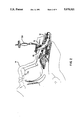
- FIG. 2 is a schematic representation of the invention in a patient.
- FIG. 3 is a cross sectional view of the invention.
- FIG. 4 is a block diagram of the invention.
- the apparatus 10 is comprised of a tracheotomy tube 16 for fitting into the trachea 12.
- the apparatus 10 is also comprised of means for warning when the tracheotomy tube 16 becomes obstructed to air flow.
- the warning means includes a sensor in contact with the tracheotomy tube 16 for sensing when the tracheotomy tube 16 becomes obstructed.
- Both apparatuses include an alarm means 18 in communication with the sensor and which indicates when the tube 16 is obstructed.
- the senor includes at least one temperature sensor 20 disposed such that the temperature of the air in the tracheotomy tube 16 is sensed and produces a temperature sensor signal corresponding to the air temperature in the tracheotomy tube 16.
- the temperature sensor 20 is in electrical connection with the alarm means 18.
- the sensor includes a capacitor 22 disposed in the tracheotomy tube 16 such that the capacitance of the capacitor 22 corresponds to the percent occlusion of the tube 16 by the obstruction.
- the apparatus 10 includes an inner cannula 24 with the capacitor 22 disposed therein such that the capacitance of the capacitor 22 corresponds to the percent occlusion of the inner cannula 24 by an obstruction therein.
- the alarm means 18 is electrically connected to the capacitor 22 to indicate when the inner cannula 24 is obstructed.
- an outer cannula 26 with an obturator (not shown) disposed therein is inserted into the trachea 12 of the patient 14.
- the bladder 30 not present in all tubes positioned about the outer cannula 26 of the trachea tube 16 is expanded to the proper position to anchor the tube 16 in the trachea 12 of the patient 14.
- the obturator is then removed and the inner cannula 24 is inserted into the outer cannula 26.
- Temperature sensors 20 disposed in the end 32 of the inner cannula 24 which extends out of patient 14 senses the temperature of the air passing in and out of the patient through the trachea tube 16. The temperature of the air which is exhaled is several degrees warmer than the temperature of the air inhaled in a typical hospital environment.
- a first lead 34 connected to the temperature sensors 20 is also connected to the first signal processing circuit 36 disposed in a housing 38 fitted onto the patient 14, for instance in a pocket of his or her pajamas.
- the first signal processing circuit 36 provides a processed signal to a first alarm circuit 40.
- the first alarm circuit 40 which is powered by a battery 42 provides an alarm signal to an audio visual alarm 44, when the temperature sensors 20 do not detect a change in air temperature over a preset time interval period.
- a failure in the air temperature change in time set can be due to dislodging of the inner cannula 24 or cessation of breathing patterns due to some failure in the physiology of the patient, or the trachea tube 16 coming out of the patient 14.
- first plate 48 and second plate 50 with insulation 52 disposed therebetween, all of which are built into the inner cannula 24.
- the first plate 48 and second plate 50 together form a capacitor 22.
- Second leads 54 connected to the first plate 48 and second plate 50 extend out to a low frequency oscillator 56 in the housing 38.
- a signal from the oscillator 56 received by a second signal processing circuit 58 which processes the signal and provides it to a second alarm circuit 60.
- the alarm circuit 60 provides that signal to a display 62 which displays the percent occlusion of the inner cannula 24. If the percent occlusion is over a predetermined amount, the audio visual alarm 44 is activated.
- the display 62, second alarm circuit 60, second signal processing circuit 58 and low frequency oscillator 56 are also powered by the batteries 42.
- the capacitance of the capacitor 22 corresponds to the percentage occlusion in the inner cannula 24.
Abstract
Description
Claims (2)
Priority Applications (2)
| Application Number | Priority Date | Filing Date | Title |
|---|---|---|---|
| US07/539,694 US5070321A (en) | 1990-06-18 | 1990-06-18 | Warning apparatus for a tracheotomy tube |
| US07/876,525 US5367292A (en) | 1990-06-18 | 1992-04-30 | Warning apparatus for a tracheotomy tube |
Applications Claiming Priority (1)
| Application Number | Priority Date | Filing Date | Title |
|---|---|---|---|
| US07/539,694 US5070321A (en) | 1990-06-18 | 1990-06-18 | Warning apparatus for a tracheotomy tube |
Related Child Applications (1)
| Application Number | Title | Priority Date | Filing Date |
|---|---|---|---|
| US07/876,525 Continuation-In-Part US5367292A (en) | 1990-06-18 | 1992-04-30 | Warning apparatus for a tracheotomy tube |
Publications (1)
| Publication Number | Publication Date |
|---|---|
| US5070321A true US5070321A (en) | 1991-12-03 |
Family
ID=24152266
Family Applications (1)
| Application Number | Title | Priority Date | Filing Date |
|---|---|---|---|
| US07/539,694 Expired - Fee Related US5070321A (en) | 1990-06-18 | 1990-06-18 | Warning apparatus for a tracheotomy tube |
Country Status (1)
| Country | Link |
|---|---|
| US (1) | US5070321A (en) |
Cited By (10)
| Publication number | Priority date | Publication date | Assignee | Title |
|---|---|---|---|---|
| US5485833A (en) * | 1994-06-10 | 1996-01-23 | Dietz; Henry G. | Breath exposure synchronizer |
| GB2310605A (en) * | 1996-02-27 | 1997-09-03 | Smiths Industries Plc | Tracheostomy tube and obturator |
| JPH09290023A (en) * | 1996-04-26 | 1997-11-11 | Sekisui Chem Co Ltd | Tracheotomy catheter |
| JP2001516624A (en) * | 1997-09-18 | 2001-10-02 | アメリカ合衆国 | Spontaneous breathing apparatus and method |
| US6662032B1 (en) | 1999-07-06 | 2003-12-09 | Intercure Ltd. | Interventive-diagnostic device |
| US20040116784A1 (en) * | 2002-12-13 | 2004-06-17 | Intercure Ltd. | Apparatus and method for beneficial modification of biorhythmic activity |
| US7416532B1 (en) * | 2000-10-23 | 2008-08-26 | Loretta Broshears Doughty | Trach sensory alert system |
| US20190232004A1 (en) * | 2016-09-29 | 2019-08-01 | The Regents Of The University Of California | Tracheotomy Tube-Based Monitoring Systems And Methods |
| US10576355B2 (en) | 2002-08-09 | 2020-03-03 | 2Breathe Technologies Ltd. | Generalized metronome for modification of biorhythmic activity |
| WO2023220171A1 (en) * | 2022-05-11 | 2023-11-16 | Bioventures, Llc | Tracheal collar with integrated sensors |
Citations (4)
| Publication number | Priority date | Publication date | Assignee | Title |
|---|---|---|---|---|
| US3635082A (en) * | 1969-04-23 | 1972-01-18 | United States Steel Corp | Apparatus for measuring mass flow of fluidborne solids |
| US3903876A (en) * | 1972-09-08 | 1975-09-09 | Univ Leland Stanford Junior | Respiration monitor |
| US4014206A (en) * | 1975-03-31 | 1977-03-29 | Akron City Hospital | Apparatus and method for monitoring air emboli during extracorporeal circulation |
| US4182344A (en) * | 1977-08-19 | 1980-01-08 | G. D. Searle & Co., Limited | Pressure control tracheal device |
-
1990
- 1990-06-18 US US07/539,694 patent/US5070321A/en not_active Expired - Fee Related
Patent Citations (4)
| Publication number | Priority date | Publication date | Assignee | Title |
|---|---|---|---|---|
| US3635082A (en) * | 1969-04-23 | 1972-01-18 | United States Steel Corp | Apparatus for measuring mass flow of fluidborne solids |
| US3903876A (en) * | 1972-09-08 | 1975-09-09 | Univ Leland Stanford Junior | Respiration monitor |
| US4014206A (en) * | 1975-03-31 | 1977-03-29 | Akron City Hospital | Apparatus and method for monitoring air emboli during extracorporeal circulation |
| US4182344A (en) * | 1977-08-19 | 1980-01-08 | G. D. Searle & Co., Limited | Pressure control tracheal device |
Non-Patent Citations (2)
| Title |
|---|
| "The Breath of Life . . . New Old . . . Radio Transmitter for Helmet Puts the X on Brain", Popular Mechanics, Jan. '71. |
| The Breath of Life . . . New Old . . . Radio Transmitter for Helmet Puts the X on Brain , Popular Mechanics, Jan. 71. * |
Cited By (20)
| Publication number | Priority date | Publication date | Assignee | Title |
|---|---|---|---|---|
| US5485833A (en) * | 1994-06-10 | 1996-01-23 | Dietz; Henry G. | Breath exposure synchronizer |
| GB2310605A (en) * | 1996-02-27 | 1997-09-03 | Smiths Industries Plc | Tracheostomy tube and obturator |
| GB2310605B (en) * | 1996-02-27 | 1999-04-07 | Smiths Industries Plc | Tracheal assemblies |
| JPH09290023A (en) * | 1996-04-26 | 1997-11-11 | Sekisui Chem Co Ltd | Tracheotomy catheter |
| JP2001516624A (en) * | 1997-09-18 | 2001-10-02 | アメリカ合衆国 | Spontaneous breathing apparatus and method |
| US8183453B2 (en) | 1999-07-06 | 2012-05-22 | Intercure Ltd. | Interventive-diagnostic device |
| US10314535B2 (en) | 1999-07-06 | 2019-06-11 | 2Breathe Technologies Ltd. | Interventive-diagnostic device |
| US20100037753A1 (en) * | 1999-07-06 | 2010-02-18 | Naphtali Wagner | Interventive-diagnostic device |
| US7717858B2 (en) | 1999-07-06 | 2010-05-18 | Intercure Ltd. | Interventive-diagnostic device |
| US6662032B1 (en) | 1999-07-06 | 2003-12-09 | Intercure Ltd. | Interventive-diagnostic device |
| US8658878B2 (en) | 1999-07-06 | 2014-02-25 | Intercure Ltd. | Interventive diagnostic device |
| US9446302B2 (en) | 1999-07-06 | 2016-09-20 | 2Breathe Technologies Ltd. | Interventive-diagnostic device |
| US7416532B1 (en) * | 2000-10-23 | 2008-08-26 | Loretta Broshears Doughty | Trach sensory alert system |
| US10576355B2 (en) | 2002-08-09 | 2020-03-03 | 2Breathe Technologies Ltd. | Generalized metronome for modification of biorhythmic activity |
| US8672852B2 (en) | 2002-12-13 | 2014-03-18 | Intercure Ltd. | Apparatus and method for beneficial modification of biorhythmic activity |
| US10531827B2 (en) | 2002-12-13 | 2020-01-14 | 2Breathe Technologies Ltd. | Apparatus and method for beneficial modification of biorhythmic activity |
| US20040116784A1 (en) * | 2002-12-13 | 2004-06-17 | Intercure Ltd. | Apparatus and method for beneficial modification of biorhythmic activity |
| US20190232004A1 (en) * | 2016-09-29 | 2019-08-01 | The Regents Of The University Of California | Tracheotomy Tube-Based Monitoring Systems And Methods |
| US11690966B2 (en) * | 2016-09-29 | 2023-07-04 | The Regents Of The University Of California | Tracheotomy tube-based monitoring systems and methods |
| WO2023220171A1 (en) * | 2022-05-11 | 2023-11-16 | Bioventures, Llc | Tracheal collar with integrated sensors |
Similar Documents
| Publication | Publication Date | Title |
|---|---|---|
| US5367292A (en) | Warning apparatus for a tracheotomy tube | |
| Hess | Tracheostomy tubes and related appliances | |
| US5329921A (en) | Endotracheal tube | |
| US6394093B1 (en) | Nasopharyngeal airway with inflatable cuff | |
| White et al. | When to change a tracheostomy tube | |
| Mathew et al. | Pharyngeal airway obstruction in preterm infants during mixed and obstructive apnea | |
| McCulloch et al. | Complications of translaryngeal intubation | |
| US5070321A (en) | Warning apparatus for a tracheotomy tube | |
| Levy | Nasogastric and nasoenteric feeding tubes | |
| US20160199608A1 (en) | System and method of expediting weaning from ventilator support including an artificial airway cleaning apparatus | |
| Szekely et al. | Problems related to the endotracheal tube: an analysis of 2000 incident reports | |
| Mace | Cricothyrotomy | |
| Dunn et al. | Endotracheal tubes and airway appliances | |
| CN111939412B (en) | Airway management device with sight glass and monitoring function | |
| Stemmer et al. | Fatal complications of tracheotomy | |
| LINDHOLM et al. | Tracheal tube and cuff problems | |
| US20180169363A1 (en) | Endotracheal tube having outer and inner cannulae | |
| WO1995011716A1 (en) | Integrated end tidal carbon dioxide monitor and endotracheal tube | |
| SU589988A1 (en) | Tracheosthomy tube | |
| Maroof et al. | Post‐thyroidectomy vocal cord examination by fibreoscopy aided by the laryngeal mask airway | |
| El-Refai et al. | Comparative study between Baska and I-gel in spontaneously ventilated females undergoing minor gynecological procedures | |
| CN215275233U (en) | Nasopharynx pipe of ventilating | |
| CN211434616U (en) | Special oxygen inhalation tube for trachea cannula oxygen therapy | |
| Mishra et al. | Post-Tracheostomy Care in ICU Patients | |
| CN213252182U (en) | Nasopharyngeal airway |
Legal Events
| Date | Code | Title | Description |
|---|---|---|---|
| AS | Assignment |
Owner name: EINHORN, ROBERT K., NEW YORK Free format text: ASSIGNMENT OF A PART OF ASSIGNORS INTEREST;ASSIGNORS:EINHORN, ROBERT K.;SZOKE, ISTVAN;REEL/FRAME:005343/0757 Effective date: 19900615 Owner name: SZOKE, ISTVAN, NEW YORK Free format text: ASSIGNMENT OF A PART OF ASSIGNORS INTEREST;ASSIGNORS:EINHORN, ROBERT K.;SZOKE, ISTVAN;REEL/FRAME:005343/0757 Effective date: 19900615 Owner name: SCHWARTZ, ANSEL M., PENNSYLVANIA Free format text: ASSIGNMENT OF A PART OF ASSIGNORS INTEREST;ASSIGNORS:EINHORN, ROBERT K.;SZOKE, ISTVAN;REEL/FRAME:005343/0757 Effective date: 19900615 |
|
| REMI | Maintenance fee reminder mailed | ||
| LAPS | Lapse for failure to pay maintenance fees | ||
| FP | Expired due to failure to pay maintenance fee |
Effective date: 19951206 |
|
| STCH | Information on status: patent discontinuation |
Free format text: PATENT EXPIRED DUE TO NONPAYMENT OF MAINTENANCE FEES UNDER 37 CFR 1.362 |