US4922625A - Sectionalized centrifugal drying basket/screen assembly - Google Patents
Sectionalized centrifugal drying basket/screen assembly Download PDFInfo
- Publication number
- US4922625A US4922625A US07/163,804 US16380488A US4922625A US 4922625 A US4922625 A US 4922625A US 16380488 A US16380488 A US 16380488A US 4922625 A US4922625 A US 4922625A
- Authority
- US
- United States
- Prior art keywords
- screen
- basket
- assembly
- screen assembly
- rotation
- Prior art date
- Legal status (The legal status is an assumption and is not a legal conclusion. Google has not performed a legal analysis and makes no representation as to the accuracy of the status listed.)
- Expired - Lifetime
Links
Images

Classifications
-
- B—PERFORMING OPERATIONS; TRANSPORTING
- B04—CENTRIFUGAL APPARATUS OR MACHINES FOR CARRYING-OUT PHYSICAL OR CHEMICAL PROCESSES
- B04B—CENTRIFUGES
- B04B7/00—Elements of centrifuges
- B04B7/08—Rotary bowls
- B04B7/18—Rotary bowls formed or coated with sieving or filtering elements
-
- F—MECHANICAL ENGINEERING; LIGHTING; HEATING; WEAPONS; BLASTING
- F26—DRYING
- F26B—DRYING SOLID MATERIALS OR OBJECTS BY REMOVING LIQUID THEREFROM
- F26B5/00—Drying solid materials or objects by processes not involving the application of heat
- F26B5/08—Drying solid materials or objects by processes not involving the application of heat by centrifugal treatment
Definitions
- This invention relates to a drying screen and basket for a centrifugal dryer used to remove water and fines from an aqueous slurry of pulverized coal.
- Pulverized coal slurry centrifugal driers may include a frustoconical screen, supported by a basket of similar geometry, both supported for rotation about a vertical axis, and downwardly divergent.
- the screen/basket assembly is rapidly rotated (e.g., at 600-900 rpm), and slurry is introduced into the top end of the assembly.
- the slurry strikes the screen at its top interior, and tends to move downward to the larger diameter portion of the screen as the slurry is centrifuged.
- Water and fines smaller than the screen openings escape through the screen, while larger particles are harvested by a more slowly rotating (e.g., 75 rpm) tapered auger blade which plows these larger particles downward to an outfeed conveyor.
- the fines and water are directed to a separate trough, from which they are removed as waste.
- the clearance between the auger blade and the screen interior is on the order of 0.010-0.015 inches.
- Drier screen being of fine mesh, are susceptible to abrasive wear in service, and in fact, these screens must be replaced with great frequency. Any replacement is attended by considerable downtime, and not inconsiderable expense. Presently, the entire screen must be replaced when it is worn, despite the fact that the wear is almost exclusively confined to the point of the screen which bears the initial impact of the slurry, that is, the top few inches of the screen.
- This object is achieved by providing a centrifugal drying basket/screen assembly formed in two sections: a lower major section, and a smaller upper section, so that only the upper section need be regularly replaced. The lower portion of the assembly can be replaced only as needed, on a much more infrequent basis.
- a further object of the invention is to reduce the effect of slurry impact at the upper portion of a two-part screen/basket assembly, and thus prolong the life of even the upper portion.
- This objective is satisfied by creating a circumferential ridge on the interior surface of the drying screen, just below the point of initial slurry impact.
- the ridge acts as a dam, preventing particles from passing downward along the screen at that point, so that a cake of particles are built up inside the screen at that point. This cake then receives direct impact from entering particles, thus protecting the underlying screen.
- a further object of the invention is to provide a centrifugal coal dryer with a basket/screen assembly having integral fins to create a vacuum to assist in removing water from the slurry.
- Another object of the invention is to provide a two-part basket/screen assembly that is easily disassembled and rebuilt. Other objects of the invention will be apparent from the following description.
- the invention is summarized as a two-part centrifugal drying screen/basket assembly for a coal slurry, wherein the screen is provided in two sections, the upper section being readily replaceable for more frequent replacement than the lower section.
- the interior of the upper screen may have a circumferential ridge created around its interior to establish an impact-absorbing layer of particles at the point of slurry introduction.
- the upper and lower basket sections may have air vanes affixed to the exterior thereof to create a vacuum at the exterior of the drying screen.
- FIG. 1 shows a prior are one-piece drying basket, in a conventional environment.
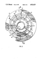
- FIG. 2 is a top view of a two-part basket assembly embodying the invention, partially broken away to show the underlying screen.
- FIG. 3 is a sectional view of the invention, taken along the longitudinal plane III-III in FIG. 2.
- FIG. 1 A conventional centrifugal dryer for coal slurry is shown in FIG. 1.
- the dryer comprises a rotary housing 10, shown in phantom, which supports along a vertical axis of rotation an inlet funnel 12.
- a frustoconical screen 14, and a matching frustoconical auger blade 16 are rotably supported within the housing.
- the blade which clears the screen by only about 0.010-0.015 inch, is supported on a shaft 18 that rotates more slowly than does the screen, so as to scrape or plow coal particles from the screen to an outfeed conveyor, not shown.
- the screen is unitary, so that the entire screen must be replaced once the upper end of the screen is breached or otherwise damaged by the abrasive effect of incoming slurry.
- FIGS. 2 and 3 show two views of a basket/screen assembly embodying the invention.
- This assembly is a bolt-in replacement for the conventional screen/basket assembly, so that no modification to the existing dryer structure is required.
- the overall dimensions are substantially those of the conventional structure.
- the basket/screen assembly comprises a basket assembly 22 supporting therein a screen assembly 58. Both assemblies are frustoconical in shape, diverging downward in their installed orientation, about a common vertical axis of rotation.
- the basket assembly 22 comprises an upper part 26 and a lower part 28.
- the upper part 26 includes a top flange 30 connected by a plurality of bars 32 to a bottom flange 34. Each of the bars extends substantially along a generatrix of the conical surface which defines the envelope of the basket.
- a support ring 36 is welded inside the bars 32 intermediate the top and bottom flanges, to support the screen.
- the bottom flange 34 has a plurality of circumferentially spaced bolt holes 38 extending therethrough, at the locus of a circumferential groove 40 formed in the bottom axial face of the bottom flange 34.
- the lower basket part 28 is similar in construction to the upper section, having an upper flange 42 connected via a plurality of bars 44 to a lower flange 46.
- a second intermediate ring 48 is connected within the bars to support the screen, and the upper flange has an upwardly protruding circumferential ridge 50 in its top axial surface, configured to fit within the groove 40 to locate the upper basket part radially with respect to the lower basket part when the two are joined by bolts (not shown, for clarity).
- a plurality of circumferentially spaced vanes 52 are connected by welding to the upper surface of the lower flange 46.
- the orientation of the vanes is seen in FIG. 3, looking down on the counter-clockwise rotating assembly.
- Each vane, formed of plate material, extends in a substantially vertical plane upward from the flange; the plane is angled at about 45° with respect to a radial plane.
- a similar set of vanes 54 is affixed to the bottom flange 34 of the upper basket part.
- the screen assembly 58 of the invention comprises an upper section 60 and a lower section 80.
- the upper section includes in major part a substantially frustoconical sieve 62 adapted to nest within the upper basket part.
- the sieve comprises a great plurality of circumferentially spaced parallel slots approximately 0.010 inch wide, each extending between an internal upper flange 66 and an external lower flange 68. To maintain slot width, two beads 70, 72 are welded around the outside of the sieve, straddling the support ring 36.
- a ridge 74 is formed by welding. I prefer for the ridge to be about one-eighth inch deep and three-sixteenths of an inch wide. The ridge 74 is placed just below the level at which coal slurry first impinges on the screen as it exits the funnel bottom.
- the lower screen section 80 comprises similarly, a sieve 82 bounded by upper and lower external flanges 86 and 88 respectively, with external reinforcing beads 90, 92 welded around the screen.
- the lower flange 88 has a plurality of holes 94 alignable with holes 96 in the lower basket flange 46, to receive bolts (not shown).
- the screen/basket assembly is constructed as follows.
- the upper screen portion 60 is nested within the upper basket part 26, whereupon the top of the upper screen portion protrudes about three-quarters of an inch above the top flange 30 of the basket, and the lower flange of the upper screen section abuts the lower flange 34 of the upper basket part.
- the screen flange 68 is then clamped between the basket flanges 34 and 42 as the upper and lower baskets are bolted together. Finally, the lower screen section 80 is nested within the lower basket part 28, and is bolted to the bottom flange of the lower basket part. The basket/screen assembly is thereafter installed in the centrifugal dryer.
- the basket/screen assembly is rotated by application of torque to its lower flange 46 from another portion of the apparatus (not shown) at 600-900 rpm, in the counterclockwise direction as seen from above.
- a conventional auger blade is rotated in the same direction within the basket at a much slower speed.
- Coal slurry is introduced via a funnel into the upper end of the upper screen section 60, where it impinges upon the sieve interior 62 at a point just above the internal ridge 74.
- the ridge acts as a dam, a cake of coal particles quickly builds up on the screen at this point, and the cake takes the brunt of the particle impact thereafter. A marked prolongation of screen life is observed, owing to the provision of the ridge.
- the basket could be made as one piece, or the screen could be provided with reinforcement and impact abrasion preventing means other than that described above.
Abstract
Description
Claims (8)
Priority Applications (2)
| Application Number | Priority Date | Filing Date | Title |
|---|---|---|---|
| US07/163,804 US4922625A (en) | 1988-03-03 | 1988-03-03 | Sectionalized centrifugal drying basket/screen assembly |
| US07/503,509 US5125166A (en) | 1988-03-03 | 1989-12-01 | Sectionalized centrifugal drying basket/screen assembly |
Applications Claiming Priority (1)
| Application Number | Priority Date | Filing Date | Title |
|---|---|---|---|
| US07/163,804 US4922625A (en) | 1988-03-03 | 1988-03-03 | Sectionalized centrifugal drying basket/screen assembly |
Related Child Applications (1)
| Application Number | Title | Priority Date | Filing Date |
|---|---|---|---|
| US07/503,509 Continuation US5125166A (en) | 1988-03-03 | 1989-12-01 | Sectionalized centrifugal drying basket/screen assembly |
Publications (1)
| Publication Number | Publication Date |
|---|---|
| US4922625A true US4922625A (en) | 1990-05-08 |
Family
ID=22591646
Family Applications (1)
| Application Number | Title | Priority Date | Filing Date |
|---|---|---|---|
| US07/163,804 Expired - Lifetime US4922625A (en) | 1988-03-03 | 1988-03-03 | Sectionalized centrifugal drying basket/screen assembly |
Country Status (1)
| Country | Link |
|---|---|
| US (1) | US4922625A (en) |
Cited By (17)
| Publication number | Priority date | Publication date | Assignee | Title |
|---|---|---|---|---|
| US5125166A (en) * | 1988-03-03 | 1992-06-30 | Process Equipment Company | Sectionalized centrifugal drying basket/screen assembly |
| US5150532A (en) * | 1990-10-04 | 1992-09-29 | Seiichiro Aigo | Lid member having a filter medium for a spin dryer |
| US5256289A (en) * | 1991-11-04 | 1993-10-26 | Centrifugal & Mechanical Industries, Inc. | Centrifugal separator incorporating structure to reduce abrasive wear |
| US5410795A (en) * | 1993-10-12 | 1995-05-02 | Centrifugal & Mechanical Industries, Inc. | Method of assembly and apparatus for a screen in a centrifugal separator |
| US5558770A (en) * | 1995-07-03 | 1996-09-24 | Elgin National Industries, Inc. | Centrifugal separator having a cone frustum |
| US5676835A (en) * | 1994-08-08 | 1997-10-14 | Derton; Harry E. | Horizontal vibratory centrifuge |
| US5720877A (en) * | 1996-02-16 | 1998-02-24 | Dudley; Robert H. | Wringer bowl assembly for use in a centrifugal separator |
| US6109452A (en) * | 1998-06-04 | 2000-08-29 | Baker Hughes Incorporated | Centrifuge with partial wear resistant basket |
| US6298575B1 (en) * | 1999-10-04 | 2001-10-09 | James Edward Aikins | Passive spin dryer for continuous and batch processing |
| US6663774B2 (en) | 2000-10-16 | 2003-12-16 | Weatherford/Lamb, Inc. | Centrifuge screen |
| US20040055947A1 (en) * | 2002-09-23 | 2004-03-25 | Michael Appel | Clamping-hook ring |
| US20040149633A1 (en) * | 2001-05-30 | 2004-08-05 | Borje Fredriksson | Screen for screening of pulp suspensions |
| US20080072447A1 (en) * | 2006-09-20 | 2008-03-27 | Econ Maschinenbau Und Steuerungstechnik Gmbh | Device for draining and drying solids, in particular plastics granulated under water |
| US20110006016A1 (en) * | 2009-07-13 | 2011-01-13 | Gilles Stephen R | Centrifugal basket assembly with segmented dam and method |
| EP3110556A4 (en) * | 2014-02-24 | 2018-05-23 | Weir Minerals Australia Ltd | Centrifugal screen assembly |
| CN109201348A (en) * | 2018-09-03 | 2019-01-15 | 安徽屹翔滤材有限公司 | A kind of detachable basket |
| WO2020194169A1 (en) | 2019-03-22 | 2020-10-01 | Flsmidth A/S | Centrifugal separator and screen having blades for same |
Citations (12)
| Publication number | Priority date | Publication date | Assignee | Title |
|---|---|---|---|---|
| US2745193A (en) * | 1954-11-17 | 1956-05-15 | Allan L Ladd | Drier |
| US3108067A (en) * | 1960-10-14 | 1963-10-22 | Braunschweigische Maschb Ansta | Centrifugal apparatus |
| US3349919A (en) * | 1964-09-28 | 1967-10-31 | Rosaen Filter Co | Telescoping filter assembly |
| US3480148A (en) * | 1967-02-02 | 1969-11-25 | Metal Tech Inc | Conical honeycomb structure |
| US3485376A (en) * | 1967-06-19 | 1969-12-23 | Peterson Filters & Eng Co | Disc filter sector assembly and separable components thereof |
| US3955754A (en) * | 1974-05-24 | 1976-05-11 | Braunschweigische Maschinenbauanstalt | Continuously operating centrifuge having a plurality of separating screens |
| US4193503A (en) * | 1978-07-17 | 1980-03-18 | Connolly James D | Slurry screen |
| US4247392A (en) * | 1979-06-27 | 1981-01-27 | Goncharov Evgeny S | Screen for vibrating centrifugal separation machines |
| US4444658A (en) * | 1981-08-10 | 1984-04-24 | Crane Co. | Rotating biological contactor apparatus |
| US4487695A (en) * | 1983-12-27 | 1984-12-11 | Connolly James D | Centrifuge screen basket |
| US4555055A (en) * | 1982-08-06 | 1985-11-26 | Connolly James D | Method of making centrifuge screen baskets |
| US4762570A (en) * | 1986-08-22 | 1988-08-09 | Braunschweigische Maschinenbauanstalt Ag | Continuously operable sugar centrifuge |
-
1988
- 1988-03-03 US US07/163,804 patent/US4922625A/en not_active Expired - Lifetime
Patent Citations (12)
| Publication number | Priority date | Publication date | Assignee | Title |
|---|---|---|---|---|
| US2745193A (en) * | 1954-11-17 | 1956-05-15 | Allan L Ladd | Drier |
| US3108067A (en) * | 1960-10-14 | 1963-10-22 | Braunschweigische Maschb Ansta | Centrifugal apparatus |
| US3349919A (en) * | 1964-09-28 | 1967-10-31 | Rosaen Filter Co | Telescoping filter assembly |
| US3480148A (en) * | 1967-02-02 | 1969-11-25 | Metal Tech Inc | Conical honeycomb structure |
| US3485376A (en) * | 1967-06-19 | 1969-12-23 | Peterson Filters & Eng Co | Disc filter sector assembly and separable components thereof |
| US3955754A (en) * | 1974-05-24 | 1976-05-11 | Braunschweigische Maschinenbauanstalt | Continuously operating centrifuge having a plurality of separating screens |
| US4193503A (en) * | 1978-07-17 | 1980-03-18 | Connolly James D | Slurry screen |
| US4247392A (en) * | 1979-06-27 | 1981-01-27 | Goncharov Evgeny S | Screen for vibrating centrifugal separation machines |
| US4444658A (en) * | 1981-08-10 | 1984-04-24 | Crane Co. | Rotating biological contactor apparatus |
| US4555055A (en) * | 1982-08-06 | 1985-11-26 | Connolly James D | Method of making centrifuge screen baskets |
| US4487695A (en) * | 1983-12-27 | 1984-12-11 | Connolly James D | Centrifuge screen basket |
| US4762570A (en) * | 1986-08-22 | 1988-08-09 | Braunschweigische Maschinenbauanstalt Ag | Continuously operable sugar centrifuge |
Cited By (23)
| Publication number | Priority date | Publication date | Assignee | Title |
|---|---|---|---|---|
| US5125166A (en) * | 1988-03-03 | 1992-06-30 | Process Equipment Company | Sectionalized centrifugal drying basket/screen assembly |
| US5150532A (en) * | 1990-10-04 | 1992-09-29 | Seiichiro Aigo | Lid member having a filter medium for a spin dryer |
| US5256289A (en) * | 1991-11-04 | 1993-10-26 | Centrifugal & Mechanical Industries, Inc. | Centrifugal separator incorporating structure to reduce abrasive wear |
| US5410795A (en) * | 1993-10-12 | 1995-05-02 | Centrifugal & Mechanical Industries, Inc. | Method of assembly and apparatus for a screen in a centrifugal separator |
| US5676835A (en) * | 1994-08-08 | 1997-10-14 | Derton; Harry E. | Horizontal vibratory centrifuge |
| US5558770A (en) * | 1995-07-03 | 1996-09-24 | Elgin National Industries, Inc. | Centrifugal separator having a cone frustum |
| US5720877A (en) * | 1996-02-16 | 1998-02-24 | Dudley; Robert H. | Wringer bowl assembly for use in a centrifugal separator |
| US6514421B2 (en) | 1998-06-04 | 2003-02-04 | Baker Hughes, Inc. | Method for separating a liquid-solid slurry |
| US6267250B1 (en) | 1998-06-04 | 2001-07-31 | Baker Hughes, Incorporated | Centrifuge with partial wear resistant basket |
| US6109452A (en) * | 1998-06-04 | 2000-08-29 | Baker Hughes Incorporated | Centrifuge with partial wear resistant basket |
| US6298575B1 (en) * | 1999-10-04 | 2001-10-09 | James Edward Aikins | Passive spin dryer for continuous and batch processing |
| US6663774B2 (en) | 2000-10-16 | 2003-12-16 | Weatherford/Lamb, Inc. | Centrifuge screen |
| US20040149633A1 (en) * | 2001-05-30 | 2004-08-05 | Borje Fredriksson | Screen for screening of pulp suspensions |
| US6761821B2 (en) | 2002-09-23 | 2004-07-13 | Weatherford/Lamb, Inc. | Clamping-hook ring |
| US20040055947A1 (en) * | 2002-09-23 | 2004-03-25 | Michael Appel | Clamping-hook ring |
| US20080072447A1 (en) * | 2006-09-20 | 2008-03-27 | Econ Maschinenbau Und Steuerungstechnik Gmbh | Device for draining and drying solids, in particular plastics granulated under water |
| US8037618B2 (en) * | 2006-09-20 | 2011-10-18 | Econ Maschinenbau Und Steuerungstechnik Gmbh | Device for draining and drying solids, in particular plastics granulated under water |
| US20110006016A1 (en) * | 2009-07-13 | 2011-01-13 | Gilles Stephen R | Centrifugal basket assembly with segmented dam and method |
| US8192634B2 (en) | 2009-07-13 | 2012-06-05 | Gilles Stephen R | Centrifugal basket assembly with segmented dam and method |
| EP3110556A4 (en) * | 2014-02-24 | 2018-05-23 | Weir Minerals Australia Ltd | Centrifugal screen assembly |
| US10252194B2 (en) | 2014-02-24 | 2019-04-09 | Weir Minerals Australia Ltd | Centrifugal screen assembly |
| CN109201348A (en) * | 2018-09-03 | 2019-01-15 | 安徽屹翔滤材有限公司 | A kind of detachable basket |
| WO2020194169A1 (en) | 2019-03-22 | 2020-10-01 | Flsmidth A/S | Centrifugal separator and screen having blades for same |
Similar Documents
| Publication | Publication Date | Title |
|---|---|---|
| US4922625A (en) | Sectionalized centrifugal drying basket/screen assembly | |
| US4961722A (en) | Conical screen for a vertical centrifugal separator | |
| JP4633882B2 (en) | Screen support for pellet dryer screen | |
| US5570517A (en) | Slurry dryer | |
| EP2052790B1 (en) | Sifter | |
| KR20100016626A (en) | Centrifugal pellet dryer screen with integral embossed deflector strips | |
| US6739457B2 (en) | Deflector for centrifugal pellet dryer screen | |
| US6505416B2 (en) | Centrifugal pellet dryer apparatus | |
| PL124357B1 (en) | Rotary apparatus for sifting a fibrous suspension | |
| CN103842091B (en) | Centrifugal screening plant | |
| US5125166A (en) | Sectionalized centrifugal drying basket/screen assembly | |
| US5383941A (en) | Segmented centrifugal separator scroll housing | |
| US4923131A (en) | Rotary impact crusher rotor | |
| EP0100345B1 (en) | Screen machine | |
| US4737274A (en) | Tramp material separator | |
| US5630558A (en) | Wear protective means | |
| US5263653A (en) | Twin-flow beater mill for preparing fibrous materials | |
| FI96044C (en) | Apparatus for screening fibrous cellulosic material | |
| US4579290A (en) | Convertible centrifugal rock crusher | |
| US4323190A (en) | Centrifuge bowl end attachment flanges | |
| FI118739B (en) | separation arrangements | |
| EA037367B1 (en) | Lifting wall arrangement at an end wall of a drum mill and segment of a lifting wall arrangement at an end wall of a drum mill | |
| PL107681B1 (en) | CONICAL SPARK FOR CONTINUOUS WORK | |
| EA045938B1 (en) | LIFTER ROD, DEVICE FOR UNLOADING GROUNDED MATERIAL LOCATED AT THE UNLOADING END OF THE MILL, AND METHOD FOR DISASSEMBLYING THE UNLOADING END OF THE MILL | |
| KR200300328Y1 (en) | a rotary valve |
Legal Events
| Date | Code | Title | Description |
|---|---|---|---|
| AS | Assignment |
Owner name: PROCESS EQUIPMENT COMPANY, ROUTE 1, BOX 137A, GALA Free format text: ASSIGNMENT OF ASSIGNORS INTEREST.;ASSIGNOR:FARMER, JERRY D.;REEL/FRAME:004856/0941 Effective date: 19880303 Owner name: PROCESS EQUIPMENT COMPANY,ILLINOIS Free format text: ASSIGNMENT OF ASSIGNORS INTEREST;ASSIGNOR:FARMER, JERRY D.;REEL/FRAME:004856/0941 Effective date: 19880303 |
|
| STCF | Information on status: patent grant |
Free format text: PATENTED CASE |
|
| FEPP | Fee payment procedure |
Free format text: PAYOR NUMBER ASSIGNED (ORIGINAL EVENT CODE: ASPN); ENTITY STATUS OF PATENT OWNER: SMALL ENTITY |
|
| FPAY | Fee payment |
Year of fee payment: 4 |
|
| AS | Assignment |
Owner name: CENTRIFUGAL SERVICES, INC., ILLINOIS Free format text: ASSIGNMENT OF ASSIGNORS INTEREST;ASSIGNOR:PROCESS EQUIPMENT COMPANY;REEL/FRAME:007553/0105 Effective date: 19950630 |
|
| FEPP | Fee payment procedure |
Free format text: PAYER NUMBER DE-ASSIGNED (ORIGINAL EVENT CODE: RMPN); ENTITY STATUS OF PATENT OWNER: SMALL ENTITY Free format text: PAYOR NUMBER ASSIGNED (ORIGINAL EVENT CODE: ASPN); ENTITY STATUS OF PATENT OWNER: SMALL ENTITY |
|
| FEPP | Fee payment procedure |
Free format text: PAT HLDR NO LONGER CLAIMS SMALL ENT STAT AS INDIV INVENTOR (ORIGINAL EVENT CODE: LSM1); ENTITY STATUS OF PATENT OWNER: SMALL ENTITY |
|
| FPAY | Fee payment |
Year of fee payment: 8 |
|
| FEPP | Fee payment procedure |
Free format text: PAT HOLDER CLAIMS SMALL ENTITY STATUS - SMALL BUSINESS (ORIGINAL EVENT CODE: SM02); ENTITY STATUS OF PATENT OWNER: SMALL ENTITY |
|
| FPAY | Fee payment |
Year of fee payment: 12 |
|
| AS | Assignment |
Owner name: WELLS FARGO FOOTHILL, INC. (F/K/A FOOTHILL CAPITAL Free format text: ASSIGNMENT FOR SECURITY;ASSIGNORS:NORRIS SCREEN AND MANUFACTURING, INC.;ELGIN NATIONAL INDUSTRIES, INC.;CENTRIFUGAL SERVICES, INC.;AND OTHERS;REEL/FRAME:018757/0370 Effective date: 20061227 |
|
| AS | Assignment |
Owner name: CENTRIFUGAL SERVICES, LLC (F/K/A CENTRIFUGAL SERVI Free format text: RELEASE BY SECURED PARTY;ASSIGNOR:WELLS FARGO CAPITAL FINANCE, INC. (F/K/A WELLS FARGO FOOTHILL, INC.);REEL/FRAME:026678/0247 Effective date: 20110622 Owner name: CLINCH RIVER, LLC (F/K/A CLINCH RIVER CORPORATION) Free format text: RELEASE BY SECURED PARTY;ASSIGNOR:WELLS FARGO CAPITAL FINANCE, INC. (F/K/A WELLS FARGO FOOTHILL, INC.);REEL/FRAME:026678/0247 Effective date: 20110622 Owner name: ELGIN EQUIPMENT GROUP, LLC (F/K/A ELGIN NATIONAL I Free format text: RELEASE BY SECURED PARTY;ASSIGNOR:WELLS FARGO CAPITAL FINANCE, INC. (F/K/A WELLS FARGO FOOTHILL, INC.);REEL/FRAME:026678/0247 Effective date: 20110622 Owner name: NORRIS SCREEN AND MANUFACTURING, LLC (F/K/A NORRIS Free format text: RELEASE BY SECURED PARTY;ASSIGNOR:WELLS FARGO CAPITAL FINANCE, INC. (F/K/A WELLS FARGO FOOTHILL, INC.);REEL/FRAME:026678/0247 Effective date: 20110622 |