US4901751A - Fluid control valve and system with leak detection and containment - Google Patents
Fluid control valve and system with leak detection and containment Download PDFInfo
- Publication number
- US4901751A US4901751A US07/366,729 US36672989A US4901751A US 4901751 A US4901751 A US 4901751A US 36672989 A US36672989 A US 36672989A US 4901751 A US4901751 A US 4901751A
- Authority
- US
- United States
- Prior art keywords
- chamber
- valve
- fluid
- diaphragm
- closure
- Prior art date
- Legal status (The legal status is an assumption and is not a legal conclusion. Google has not performed a legal analysis and makes no representation as to the accuracy of the status listed.)
- Expired - Lifetime
Links
Images

Classifications
-
- G—PHYSICS
- G01—MEASURING; TESTING
- G01M—TESTING STATIC OR DYNAMIC BALANCE OF MACHINES OR STRUCTURES; TESTING OF STRUCTURES OR APPARATUS, NOT OTHERWISE PROVIDED FOR
- G01M3/00—Investigating fluid-tightness of structures
- G01M3/02—Investigating fluid-tightness of structures by using fluid or vacuum
- G01M3/04—Investigating fluid-tightness of structures by using fluid or vacuum by detecting the presence of fluid at the leakage point
- G01M3/06—Investigating fluid-tightness of structures by using fluid or vacuum by detecting the presence of fluid at the leakage point by observing bubbles in a liquid pool
- G01M3/08—Investigating fluid-tightness of structures by using fluid or vacuum by detecting the presence of fluid at the leakage point by observing bubbles in a liquid pool for pipes, cables or tubes; for pipe joints or seals; for valves; for welds
-
- G—PHYSICS
- G01—MEASURING; TESTING
- G01M—TESTING STATIC OR DYNAMIC BALANCE OF MACHINES OR STRUCTURES; TESTING OF STRUCTURES OR APPARATUS, NOT OTHERWISE PROVIDED FOR
- G01M3/00—Investigating fluid-tightness of structures
- G01M3/02—Investigating fluid-tightness of structures by using fluid or vacuum
- G01M3/04—Investigating fluid-tightness of structures by using fluid or vacuum by detecting the presence of fluid at the leakage point
-
- F—MECHANICAL ENGINEERING; LIGHTING; HEATING; WEAPONS; BLASTING
- F16—ENGINEERING ELEMENTS AND UNITS; GENERAL MEASURES FOR PRODUCING AND MAINTAINING EFFECTIVE FUNCTIONING OF MACHINES OR INSTALLATIONS; THERMAL INSULATION IN GENERAL
- F16K—VALVES; TAPS; COCKS; ACTUATING-FLOATS; DEVICES FOR VENTING OR AERATING
- F16K37/00—Special means in or on valves or other cut-off apparatus for indicating or recording operation thereof, or for enabling an alarm to be given
-
- G—PHYSICS
- G01—MEASURING; TESTING
- G01M—TESTING STATIC OR DYNAMIC BALANCE OF MACHINES OR STRUCTURES; TESTING OF STRUCTURES OR APPARATUS, NOT OTHERWISE PROVIDED FOR
- G01M3/00—Investigating fluid-tightness of structures
- G01M3/02—Investigating fluid-tightness of structures by using fluid or vacuum
- G01M3/04—Investigating fluid-tightness of structures by using fluid or vacuum by detecting the presence of fluid at the leakage point
- G01M3/16—Investigating fluid-tightness of structures by using fluid or vacuum by detecting the presence of fluid at the leakage point using electric detection means
- G01M3/18—Investigating fluid-tightness of structures by using fluid or vacuum by detecting the presence of fluid at the leakage point using electric detection means for pipes, cables or tubes; for pipe joints or seals; for valves; for welds; for containers, e.g. radiators
- G01M3/184—Investigating fluid-tightness of structures by using fluid or vacuum by detecting the presence of fluid at the leakage point using electric detection means for pipes, cables or tubes; for pipe joints or seals; for valves; for welds; for containers, e.g. radiators for valves
-
- G—PHYSICS
- G01—MEASURING; TESTING
- G01M—TESTING STATIC OR DYNAMIC BALANCE OF MACHINES OR STRUCTURES; TESTING OF STRUCTURES OR APPARATUS, NOT OTHERWISE PROVIDED FOR
- G01M3/00—Investigating fluid-tightness of structures
- G01M3/38—Investigating fluid-tightness of structures by using light
-
- H—ELECTRICITY
- H01—ELECTRIC ELEMENTS
- H01H—ELECTRIC SWITCHES; RELAYS; SELECTORS; EMERGENCY PROTECTIVE DEVICES
- H01H35/00—Switches operated by change of a physical condition
- H01H35/24—Switches operated by change of fluid pressure, by fluid pressure waves, or by change of fluid flow
- H01H35/26—Details
- H01H35/2671—Means to detect leaks in the pressure sensitive element
-
- Y—GENERAL TAGGING OF NEW TECHNOLOGICAL DEVELOPMENTS; GENERAL TAGGING OF CROSS-SECTIONAL TECHNOLOGIES SPANNING OVER SEVERAL SECTIONS OF THE IPC; TECHNICAL SUBJECTS COVERED BY FORMER USPC CROSS-REFERENCE ART COLLECTIONS [XRACs] AND DIGESTS
- Y10—TECHNICAL SUBJECTS COVERED BY FORMER USPC
- Y10T—TECHNICAL SUBJECTS COVERED BY FORMER US CLASSIFICATION
- Y10T137/00—Fluid handling
- Y10T137/5762—With leakage or drip collecting
Definitions
- the present invention relates generally to fluid flow control valves and more particularly to an improved valve assembly and having leak detection means and provisions for leak containment.
- the fluid handling position of the valve is sealed from the actuating means by secondary diaphragms, 0-rings or other forms of sealing structures in order to insure against leakage past the primary diaphragm or seal and especially against leakage into the actuating means.
- flow of the liquid into the space between the first and second sealing means causes an outward flow of fluid through a venting passage which thereby provides an indication of leakage past the first sealing means so that the leak will be noticed and the first sealing means can be replaced before any damage to the actuating means or to the system itself occurs.
- valve is suitable for enabling detection of diaphragm failure, it is not directed toward applications in which corrosion or contamination of either the actuator mechanism or the fluid itself must be strictly limited.
- the processing chemicals and deionized water supplies must be kept as pure as possible since even a momentary contact of the flow stream with a contaminating surface can result in a catastrophic event.
- the valve closure member shown in FIG. 1 of De Lorenzo is indicated as being made of Teflon, the surrounding valve body and associated parts appear to be metallic and would thus not be suited for applications in which diaphragm failure is likely to cause almost immediate contamination of the controlled fluid.
- the thrust of the De Lorenzo invention is to protect the actuating mechanism from unintentional exposure to the controlled fluid as opposed to being directed to preventing contamination of the fluid.
- the valve device per se is a gate valve of a type which is not suited for certain applications in which back flow pressures can unseat the gate or perhaps even prevent its closure. And finally, no means for automatically detecting diaphragm failure is provided.
- valves of the type disclosed by De Lorenzo, et al. Another problem associated with valves of the type disclosed by De Lorenzo, et al. is that frictional engagement of sealing surfaces deleteriously affects the useful lifetime of the valve, and the tendency of the sealing surfaces to be residually deformed after closure for extended periods of time may limit the sealing ability of the device.
- the Stack U.S. Pat. Nos. to Stack 4,538,638, Botelar 3,407,838, McFarland 3,542,286 and Priese 3,451,423 disclose weir type valves are more suited to such applications. However, such devices have not been adapted to address the problem of fluid contamination as a result of the leakage and the need for immediate and automatic detection of diaphraqm failure.
- a further object of the present invention is to provide a device of the type described which includes means for providing immediate detection of diaphragm failure.
- Another object of the present invention is to provide a device of the type described having leak containment features.
- a still further object of the present invention is to provide a device of the type described having sealing surfaces which mate without substantial rubbing contact.
- a preferred embodiment of the present invention comprises a fluid handling system incorporating one or more flow controlling devices including an actuator, a weir valve and associated valve housing, a pair of spaced apart diaphragms, one of which serves as the closure member for the weir valve and the other providing a secondary seal defining the limits of a containment chamber for at once preventing contamination of the controlled fluid, protecting the actuating mechanism and allowing immediate detection of the valve closure failure.
- a piston member disposed within the chamber is coupled to the two diaphragms, and a fluid detection device is disposed in communication with the sealed containment chamber formed between the two diaphragms.
- the system includes electronic control apparatus responsive to the detection device and operation to instantaneously shut down the system in the event of a detected failure.
- An important advantage of the present invention is that even in the event of a diaphragm failure, no contamination will occur because all wetted surfaces of both valve and containment chamber components are constructed of or are coated with a chemically inert material.
- Another advantaqe of the present invention is that in the event of diaphragm failure, diaphragm leakage will be contained within the space between the two diaphragms.
- Yet another advantage of the present invention is that means is provided for immediately detecting diaphragm failure so that instantaneous shutdown of the fluid supply system can be achieved.
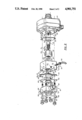
- FIG. 1 is partially broken elevational view showing a fluid control system including a valve apparatus in accordance with the present invention.
- FIG. 2 is an exploded perspective view further illustrating the components of the embodiment shown in FIG. 1.
- valve assembly 10 controls the flow of fluid in the form of either liquid or has pumped by a pump 12 from a fluid supply 14 to a fluid user 16.
- Actuating control for valve assembly 10 and pump 12 is provided by a controller 18, and a detector 20 responds to leaks within valve assembly 10 and outputs signals to controller 18 which will cause immediate shut-down of the pumping system.
- the system may include an in-line filter, as illustrated by the dashed lines 21, including a suitable pressure or, contamination detector, capable of likewise signaling controller 18.
- component parts of assembly 10 include a weir valve 22, an actuator mechanism 24, and a mechanism housing 26 which physically couples the actuator assembly to the valve body and forms a containment chamber 27.
- Actuator mechanism 24 can be of any suitable type of electrical, hydraulic or pneumatic linear actuator and includes an armature 28 which is attached to a plunger 30 by means of an actuator rod 32.
- a threaded extension 34 of armature 28 extends through an opening 35 in a diaphragm 36 to threadably engage the upper end of actuator rod 32 which is in turn threadably coupled to plunger 30.
- Diaphragm 36 is preferably made of an inert flexible plastic material such as polyetralouroethylene (PTFE), and has a formed central portion 37 which accommodates the axial motion of armature 28 and actuator rod 32.
- PTFE polyetralouroethylene
- Actuator rod 32 is preferably made of type 304 stainless steel polyfluroaloxyl (PFA), and has a female threaded bore at its upper end for receiving the threaded end 34 of armature 28.
- the lower end is externally threaded as indicated at 38 and is adapted to pass through a PTFE sealing ring 40 and is to be threadably received within the axially continuous bore of plunger 30 which will be further described below.
- PFA type 304 stainless steel polyfluroaloxyl
- Plunger 30 is a generally cylindrical body having a rounded lower surface 42 and is moveable between the valve closed position shown and the valve open position depicted by the dashed lines 30'. Extending from opposite sides of plunger 30 are guide ribs 44 which engage slots (shown in FIG. 2) formed in the internal wall 46 of housing 26 to prevent rotation of plunger 30 as it is moved up and down.
- Housing 26 is formed as a generally rectangular body made of either a molded inert plastic material or is of 304 stainless steel coated with PFA and has a cylindrically configured axial bore 46 extending therethrough. Bore 46 is provided with slots (as shown) formed in opposite sides thereof which receive the ribs 44 of plunger 30 and serve to guide and prevent rotation of plunger 30 as it moves longitudinally within bore 46. Housing 26 is also provided with a tapped bore 50 extending transversely into communication with bore 46. Bore 50 is adapted to receive the threaded end of a suitable leak trace detection probe 52.
- Valve 22 is of the weir type disclosed generally in several of the prior art patents mentioned above and is comprised of a molded valve body 56 made of PFA and has transversely directed inlet and outlet openings 58 and 60, respectively, and an internal weir 62, the upper portion of which forms a valve slot.
- the primary diaphragm assembly 64 is actually comprised of two diaphragm members 65 and 66.
- Member 65 is a molded member made of PTFE and forms the primary closure diaphragm of the valve. As indicated at 67, it includes an integrally formed rib 67 which sealing engages the top surface of weir 62 when the valve is in its closed state.
- diaphragm assembly 66 Disposed immediately adjacent and above diaphragm 65 is the supporting diaphragm assembly 66 which is of bonded composite construction and includes three layers 66, 68 and 70 made of PTFE, VITON and PTFE respectively and includes a formed central portion 72 which, as will be described below, is attached to plunger 30. Assembly 66 is provided with a durability of openings 71 which extend therethrough to provide a passage for fluid into chamber 27 in the event that the diaphragm should fail.
- valve and actuator assembly is held in place by a retaining plate 80 and four retaining bolts 82 which extend through openings in valve body 56, the diaphragms 65, and 66, the housing 26, and diaphragm 36 to be threadably received within threaded bores provided in the lower part of actuator assembly 24.
- the leak trace deprotection probe 52 preferably includes an optical detector coupled to a fiber optics conductor 53 and is comprised of a conically configured tip 51 which faces the chamber 27 formed by bore 46.
- the tip 51 has an index refraction which, when surrounded by air, has a high level of internal reflection, but when in contact with a liquid, assumes a materially different reflective characteristic. As a consequence, the level of light transmitted to the tip 51 through one or more of the fibers of conductor 53 and reflected back into other receiving fibers falls below a detection threshold and a leak is signaled.
- the secondary diaphragm 36 is generally rectangular in configuration and includes openings 39 provided at each corner for receiving the retainer bolts and allowing them to be threaded into the tapped openings 25 in the housing of actuator assembly 24.
- the central aperture 35 through which the threaded extension 34 of armature 28 is extended so that it can be threaded into the upper end of rod 32 as previously described.
- the threaded portion 38 of rod 32 is long enough to extend through the tapped bore 39 of plunger 30 to sandwich the sealing washer 76 between the distal end of rod 32 and a mating surface 77 affixed to the central portion of the upper side of diaphragm assembly 64.
- Formed integral therewith and extending upwardly (rightwardly as depicted in FIG. 2) is a threaded attachment shaft 74 which is extended through the aperture 79 in washer 76 and thence threaded into tapped bore 41 in rod 32.
- housing 26 With regard to housing 26, note that the face 27 is recessed and surrounded by a lip 29 which is notched as indicated at 31 and 33 so as to receive the alignment tabs 63 and 69 of the diaphragms 66 and 65 respectively. This insures that the diaphragms will be installed correctly and in the proper orientation so that the rib 67 will be properly aligned with the weir 62.
- each of the components 26, 66, 65, 56 and 80 includes an aperture formed in each corner thereof for receiving one of the retaining bolts 82.
- the interior surfaces of the openings 71 passing through the entire assembly are coated with a plastic such as PTFE to prevent fluid contact with the Viton layer 68.
- valve assembly 10 can be used to accurately control fluid flow from any supply, such as depicted at 14, to any user, such as depicted at 16 in FIG. 1.
- the primary diaphragm 65 should fail for any reason, the fluid leaking therethrough will immediately pass through the opening 71 in the supporting diaphraqm assembly 66 and into the chamber 27 wherein it will contact the end 51 of probe 52 and cause detector 20 to sense the presence of the leak and signal controller 18 to shut down both the pump and cause plunger 30 to be driven downwardly to halt the flow of fluid through the system.
Abstract
Description
Claims (10)
Priority Applications (7)
| Application Number | Priority Date | Filing Date | Title |
|---|---|---|---|
| US07/366,729 US4901751A (en) | 1989-06-15 | 1989-06-15 | Fluid control valve and system with leak detection and containment |
| EP19900917772 EP0477304B1 (en) | 1989-06-15 | 1990-06-15 | Fluid control valve with leak detection |
| KR1019910701868A KR960001999B1 (en) | 1989-06-15 | 1990-06-15 | Fluid control valve and system with leak detection and |
| PCT/US1990/003404 WO1990015977A1 (en) | 1989-06-15 | 1990-06-15 | Fluid control valve and system with leak detection and containment |
| AT90917772T ATE137578T1 (en) | 1989-06-15 | 1990-06-15 | LEAK TEST FLUID CONTROL VALVE |
| DE1990626824 DE69026824T2 (en) | 1989-06-15 | 1990-06-15 | FLUID CONTROL VALVE WITH LEAK DETECTION |
| JP50956390A JP2552957B2 (en) | 1989-06-15 | 1990-06-15 | Fluid control valves and systems with leak detection and containment |
Applications Claiming Priority (1)
| Application Number | Priority Date | Filing Date | Title |
|---|---|---|---|
| US07/366,729 US4901751A (en) | 1989-06-15 | 1989-06-15 | Fluid control valve and system with leak detection and containment |
Publications (1)
| Publication Number | Publication Date |
|---|---|
| US4901751A true US4901751A (en) | 1990-02-20 |
Family
ID=23444248
Family Applications (1)
| Application Number | Title | Priority Date | Filing Date |
|---|---|---|---|
| US07/366,729 Expired - Lifetime US4901751A (en) | 1989-06-15 | 1989-06-15 | Fluid control valve and system with leak detection and containment |
Country Status (7)
| Country | Link |
|---|---|
| US (1) | US4901751A (en) |
| EP (1) | EP0477304B1 (en) |
| JP (1) | JP2552957B2 (en) |
| KR (1) | KR960001999B1 (en) |
| AT (1) | ATE137578T1 (en) |
| DE (1) | DE69026824T2 (en) |
| WO (1) | WO1990015977A1 (en) |
Cited By (85)
| Publication number | Priority date | Publication date | Assignee | Title |
|---|---|---|---|---|
| US5092158A (en) * | 1990-06-15 | 1992-03-03 | Tanknology Corporation International | Apparatus for testing leak detectors |
| US5138643A (en) * | 1989-10-02 | 1992-08-11 | Canon Kabushiki Kaisha | Exposure apparatus |
| US5203370A (en) * | 1991-11-26 | 1993-04-20 | Block Gary C | Mounting apparatus with fugitive emission collection means for directly coupling a rotary valve to an actuator having rotary drive means |
| JPH05126669A (en) * | 1991-04-26 | 1993-05-21 | Kiyohara Masako | Control unit with seal section breakage detecting system |
| US5245860A (en) * | 1991-09-09 | 1993-09-21 | Intevep, S.A. | Sensor for detection of oil leaks and oil quality in stuffing box of walking beam pump system |
| US5251653A (en) * | 1993-02-12 | 1993-10-12 | Tucker Orrin E | Control system for automatic fluid shut-off |
| US5261442A (en) * | 1992-11-04 | 1993-11-16 | Bunnell Plastics, Inc. | Diaphragm valve with leak detection |
| US5335691A (en) * | 1992-05-26 | 1994-08-09 | Nupro Company | High pressure diaphragm valve |
| US5343736A (en) * | 1992-06-15 | 1994-09-06 | Systems Chemistry, Inc. | Optical leak sensor and position detector |
| US5361802A (en) * | 1991-09-30 | 1994-11-08 | Herion-Werke Kg | Valve block |
| US5372352A (en) * | 1990-09-28 | 1994-12-13 | Johnston Pump/General Valve, Inc. | Apparatus for sealing a fluid carrying device |
| US5390532A (en) * | 1993-10-18 | 1995-02-21 | Anthony; Mark | Test apparatus for a fluid dispensing system |
| US5476004A (en) * | 1994-05-27 | 1995-12-19 | Furon Company | Leak-sensing apparatus |
| US5586576A (en) * | 1994-09-28 | 1996-12-24 | Tetra Laval Holdings & Finance S.A. | Dosing valve having seal failure detection |
| US5616829A (en) * | 1995-03-09 | 1997-04-01 | Teledyne Industries Inc. | Abnormality detection/suppression system for a valve apparatus |
| WO1997039267A1 (en) * | 1996-04-18 | 1997-10-23 | Tetra Laval Holdings & Finance S.A. | Hygienic valve having leakage detection |
| US5720313A (en) * | 1996-05-24 | 1998-02-24 | Weiss Construction Co. | Flow rate control system |
| US5760292A (en) * | 1995-11-01 | 1998-06-02 | Framo Engineering As | Monitoring system for high pressure fluid flow connector |
| US5831148A (en) * | 1997-09-17 | 1998-11-03 | Marshall; Ralph B. | Capacitor bank liquid dielectric leak sensor apparatus |
| US5883299A (en) * | 1996-06-28 | 1999-03-16 | Texaco Inc | System for monitoring diaphragm pump failure |
| EP0945658A1 (en) * | 1998-03-25 | 1999-09-29 | MTS Milchtechnik AG | Process valve, in particular for sterile manufacturing |
| US5967173A (en) * | 1997-07-14 | 1999-10-19 | Furon Corporation | Diaphragm valve with leak detection |
| US6000416A (en) * | 1997-06-04 | 1999-12-14 | Furon Company | Compact valve with rolling diaphragm poppet |
| US6029506A (en) * | 1997-11-12 | 2000-02-29 | Fisher Controls International, Inc. | Sample retrieval system |
| US6050296A (en) * | 1997-06-03 | 2000-04-18 | Samson Aktiengesellschaft | Control apparatus |
| US6272903B1 (en) | 2000-02-22 | 2001-08-14 | Jon Lawrence Shafer | Pipeline valve leak indicator |
| US6321776B1 (en) * | 2000-04-24 | 2001-11-27 | Wayne L. Pratt | Double diaphragm precision throttling valve |
| US6345234B1 (en) | 1997-11-12 | 2002-02-05 | Fisher Controls International, Inc. | Fugitive emission sensing system |
| US20020100503A1 (en) * | 1998-10-09 | 2002-08-01 | Browne Ronnie A. | Sanitary diaphragm valve |
| WO2002086437A1 (en) * | 2001-03-02 | 2002-10-31 | Waters Investments Limited | Methods and apparatus for determining the presence or absence of a fluid leak |
| US20020170596A1 (en) * | 2000-07-28 | 2002-11-21 | Hiltap Fittings., Ltd. | Fluid flow management system |
| US6505814B1 (en) * | 1998-10-15 | 2003-01-14 | Kabushiki Kaisha Fujikin | Fluid controller |
| US6508266B2 (en) * | 2000-03-31 | 2003-01-21 | Toyo Stainless Steel Industries Co., Ltd. | Diaphragm valve |
| US6550314B2 (en) * | 2001-03-19 | 2003-04-22 | Sis-Tech Applications, L.L.P. | Apparatus and method for on-line detection of leaky valves |
| US6575431B2 (en) * | 1999-09-14 | 2003-06-10 | Spears Manufacturing Co. | Weir-type diaphragm valve with raised arcuate bead |
| US6592126B2 (en) | 2001-07-20 | 2003-07-15 | Flowserve Management Company | Mechanical seal leak detector |
| US6595484B1 (en) * | 1998-07-14 | 2003-07-22 | Heinz Gross | Wall structure having a deformable multi-walled area for varying a cross section of a flow channel |
| US6595240B2 (en) | 1998-12-18 | 2003-07-22 | Entegris, Inc. | Creep resistant valve |
| US6672561B2 (en) | 2002-03-28 | 2004-01-06 | Swagelok Company | Piston diaphragm with integral seal |
| US20040099311A1 (en) * | 2002-11-27 | 2004-05-27 | Smc Kabushiki Kaisha | Two-way valve |
| US20040129906A1 (en) * | 2002-12-18 | 2004-07-08 | Snecma Moteurs | Cryogenic valve device |
| US20040256589A1 (en) * | 2003-06-19 | 2004-12-23 | Laurent John Arthur | Low-leakage valve apparatus |
| US20050006617A1 (en) * | 2003-07-11 | 2005-01-13 | Leys John A. | Extended stroke valve and diaphragm |
| US20050029482A1 (en) * | 2001-03-16 | 2005-02-10 | Entegris, Inc. | Reinforced diaphragm valve |
| US20050066709A1 (en) * | 2001-03-19 | 2005-03-31 | Zachary Bryan A. | Apparatus and method for on-line detection of leaky valve seals and defective flow diverters |
| US20050147508A1 (en) * | 2002-03-01 | 2005-07-07 | Luongo Joseph A. | Methods and apparatus for determining the presence or absence of a fluid leak |
| US20060109939A1 (en) * | 2004-11-19 | 2006-05-25 | Steven Ciccarelli | Noise reduction filtering in a wireless communication system |
| US20060169937A1 (en) * | 2001-03-29 | 2006-08-03 | Nolte Hans J | Valve unit for an electrostatic coating installation |
| US20060263195A1 (en) * | 2005-05-16 | 2006-11-23 | Stefan Furthmueller | Device for stacking flat products |
| US20060278839A1 (en) * | 2003-10-24 | 2006-12-14 | Krywitsky Lee A | Quick disconnect valve assembly |
| US20060289062A1 (en) * | 2000-07-28 | 2006-12-28 | Krywitsky Lee A | Dry break valve assembly |
| US20070039657A1 (en) * | 2000-07-28 | 2007-02-22 | Hiltap Fittings, Ltd. | Fluid system coupling with pin lock |
| US20070289650A1 (en) * | 2000-07-28 | 2007-12-20 | Krywitsky Lee A | Fluid system coupling with handle actuating member |
| US20080017824A1 (en) * | 2004-07-05 | 2008-01-24 | Tyco Flow Control Pacific Pty Limited | Valve Status Monitoring |
| WO2008051871A3 (en) * | 2006-10-20 | 2008-10-16 | Tyco Fire Products Lp | Fluid control valve system and methods |
| US7614606B2 (en) * | 2003-05-13 | 2009-11-10 | Gemü Gebrüder Müller Apparatebau GmbH & Co. KG | Compressor for a diaphragm valve |
| US20100013216A1 (en) * | 2008-07-21 | 2010-01-21 | Krywitsky Lee A | Fluid system coupling with pivoting handle actuating member |
| US7717127B2 (en) * | 2005-02-10 | 2010-05-18 | Gemü Gebrüder Müller Apparatebau GmbH & Co. KG | Diaphragm valve |
| US20100161139A1 (en) * | 2008-12-23 | 2010-06-24 | Jed Stevens | System for monitoring a transient fluid |
| US20120119130A1 (en) * | 2009-07-27 | 2012-05-17 | Merck Sharp & Dohme Corp. | Diaphragm valve with improved sealing performance and leak detection |
| US8225809B2 (en) | 2000-07-28 | 2012-07-24 | Hiltap Fittings, Ltd. | Methods and apparatus for introducing a pig into a fluid system |
| US20140060029A1 (en) * | 2011-04-18 | 2014-03-06 | Andre-Heinrich Meinhof | Electropneumatic Position Regulator |
| US20140238512A1 (en) * | 2013-02-25 | 2014-08-28 | Rave N.P., Inc. | Smart Valve |
| US20140338464A1 (en) * | 2011-05-31 | 2014-11-20 | Mueller International, Llc | Valve meter assembly and method |
| WO2015020776A1 (en) * | 2013-08-07 | 2015-02-12 | Dresser, Inc. | System to monitor performance of packing material in a seal |
| WO2015108618A1 (en) * | 2013-11-19 | 2015-07-23 | Dresser, Inc. | System and method to monitor characteristics of an operating fluid in a process line |
| CN105258863A (en) * | 2015-11-11 | 2016-01-20 | 长春轨道客车股份有限公司 | Simulation detection apparatus of railway-vehicle 3-way ball valve cold resistance performance |
| US9494249B2 (en) | 2014-05-09 | 2016-11-15 | Mueller International, Llc | Mechanical stop for actuator and orifice |
| US9565620B2 (en) | 2014-09-02 | 2017-02-07 | Mueller International, Llc | Dynamic routing in a mesh network |
| US20170278372A1 (en) * | 2016-03-22 | 2017-09-28 | Watts Regulator, Inc. | Leak detector |
| US9799204B2 (en) | 2009-05-22 | 2017-10-24 | Mueller International, Llc | Infrastructure monitoring system and method and particularly as related to fire hydrants and water distribution |
| US9849322B2 (en) | 2010-06-16 | 2017-12-26 | Mueller International, Llc | Infrastructure monitoring devices, systems, and methods |
| US9934670B2 (en) | 2008-10-27 | 2018-04-03 | Mueller International, Llc | Infrastructure monitoring system and method |
| US10039018B2 (en) | 2011-10-27 | 2018-07-31 | Mueller International, Llc | Systems and methods for recovering an out-of-service node in a hierarchical network |
| RU2712955C1 (en) * | 2016-03-18 | 2020-02-03 | Роторк Юк Лимитед | Detection of fugitive emissions |
| US10692351B2 (en) * | 2015-03-05 | 2020-06-23 | Ademco Inc. | Water heater leak detection system |
| US20220113213A1 (en) * | 2019-01-10 | 2022-04-14 | Psg California Llc | Leak Detection and Containment Muffler System |
| US11703364B2 (en) | 2018-11-05 | 2023-07-18 | Watts Regulator Co. | Fluid discharge event detector |
| US11802257B2 (en) | 2022-01-31 | 2023-10-31 | Marathon Petroleum Company Lp | Systems and methods for reducing rendered fats pour point |
| US11860069B2 (en) | 2021-02-25 | 2024-01-02 | Marathon Petroleum Company Lp | Methods and assemblies for determining and using standardized spectral responses for calibration of spectroscopic analyzers |
| US11891581B2 (en) | 2017-09-29 | 2024-02-06 | Marathon Petroleum Company Lp | Tower bottoms coke catching device |
| US11898109B2 (en) | 2021-02-25 | 2024-02-13 | Marathon Petroleum Company Lp | Assemblies and methods for enhancing control of hydrotreating and fluid catalytic cracking (FCC) processes using spectroscopic analyzers |
| US11905468B2 (en) | 2021-02-25 | 2024-02-20 | Marathon Petroleum Company Lp | Assemblies and methods for enhancing control of fluid catalytic cracking (FCC) processes using spectroscopic analyzers |
| US11905479B2 (en) | 2020-02-19 | 2024-02-20 | Marathon Petroleum Company Lp | Low sulfur fuel oil blends for stability enhancement and associated methods |
| WO2024050416A1 (en) * | 2022-08-31 | 2024-03-07 | Dresser, Llc | Re-couping actuating media used to operate a control valve |
Families Citing this family (2)
| Publication number | Priority date | Publication date | Assignee | Title |
|---|---|---|---|---|
| EP2775181B1 (en) | 2013-03-08 | 2016-01-13 | Georg Fischer Rohrleitungssysteme AG | Valve with a leakage display |
| KR102067975B1 (en) * | 2019-09-18 | 2020-01-20 | 동주에이피 주식회사 | Valve system |
Citations (9)
| Publication number | Priority date | Publication date | Assignee | Title |
|---|---|---|---|---|
| US2691773A (en) * | 1951-07-23 | 1954-10-12 | Harold V Lichtenberger | Valve leak detector |
| US3148861A (en) * | 1962-06-27 | 1964-09-15 | Hills Mccanna Co | Weir valve |
| US3154286A (en) * | 1960-11-03 | 1964-10-27 | Hills Mccanna Co | Weir valve |
| US3472062A (en) * | 1967-09-13 | 1969-10-14 | Pathway Bellows Inc | Testable and pressurized multiple ply bellows |
| US3623700A (en) * | 1969-11-05 | 1971-11-30 | Grinnell Corp | Diaphragm valve |
| US3838707A (en) * | 1972-11-22 | 1974-10-01 | Alloy Prod Corp | Valve with leak detecting seal and diaphragm assembly |
| US4010769A (en) * | 1972-11-27 | 1977-03-08 | Plast-O-Matic Valves, Inc. | Leak detection arrangement for valve having sealing means |
| US4386269A (en) * | 1979-11-15 | 1983-05-31 | Avon Rubber Company Limited | Method and device for detecting leaks from pipelines |
| US4794940A (en) * | 1987-01-06 | 1989-01-03 | Coe Corporation | Plural diaphragm valve |
Family Cites Families (1)
| Publication number | Priority date | Publication date | Assignee | Title |
|---|---|---|---|---|
| JPS5632990A (en) * | 1979-08-24 | 1981-04-02 | Mitsubishi Chem Ind Ltd | T-ran (guanosine-2') metahyl transferase |
-
1989
- 1989-06-15 US US07/366,729 patent/US4901751A/en not_active Expired - Lifetime
-
1990
- 1990-06-15 AT AT90917772T patent/ATE137578T1/en not_active IP Right Cessation
- 1990-06-15 EP EP19900917772 patent/EP0477304B1/en not_active Expired - Lifetime
- 1990-06-15 JP JP50956390A patent/JP2552957B2/en not_active Expired - Lifetime
- 1990-06-15 KR KR1019910701868A patent/KR960001999B1/en not_active IP Right Cessation
- 1990-06-15 WO PCT/US1990/003404 patent/WO1990015977A1/en active IP Right Grant
- 1990-06-15 DE DE1990626824 patent/DE69026824T2/en not_active Expired - Fee Related
Patent Citations (9)
| Publication number | Priority date | Publication date | Assignee | Title |
|---|---|---|---|---|
| US2691773A (en) * | 1951-07-23 | 1954-10-12 | Harold V Lichtenberger | Valve leak detector |
| US3154286A (en) * | 1960-11-03 | 1964-10-27 | Hills Mccanna Co | Weir valve |
| US3148861A (en) * | 1962-06-27 | 1964-09-15 | Hills Mccanna Co | Weir valve |
| US3472062A (en) * | 1967-09-13 | 1969-10-14 | Pathway Bellows Inc | Testable and pressurized multiple ply bellows |
| US3623700A (en) * | 1969-11-05 | 1971-11-30 | Grinnell Corp | Diaphragm valve |
| US3838707A (en) * | 1972-11-22 | 1974-10-01 | Alloy Prod Corp | Valve with leak detecting seal and diaphragm assembly |
| US4010769A (en) * | 1972-11-27 | 1977-03-08 | Plast-O-Matic Valves, Inc. | Leak detection arrangement for valve having sealing means |
| US4386269A (en) * | 1979-11-15 | 1983-05-31 | Avon Rubber Company Limited | Method and device for detecting leaks from pipelines |
| US4794940A (en) * | 1987-01-06 | 1989-01-03 | Coe Corporation | Plural diaphragm valve |
Cited By (136)
| Publication number | Priority date | Publication date | Assignee | Title |
|---|---|---|---|---|
| US5138643A (en) * | 1989-10-02 | 1992-08-11 | Canon Kabushiki Kaisha | Exposure apparatus |
| US5092158A (en) * | 1990-06-15 | 1992-03-03 | Tanknology Corporation International | Apparatus for testing leak detectors |
| US5372352A (en) * | 1990-09-28 | 1994-12-13 | Johnston Pump/General Valve, Inc. | Apparatus for sealing a fluid carrying device |
| JPH05126669A (en) * | 1991-04-26 | 1993-05-21 | Kiyohara Masako | Control unit with seal section breakage detecting system |
| US5245860A (en) * | 1991-09-09 | 1993-09-21 | Intevep, S.A. | Sensor for detection of oil leaks and oil quality in stuffing box of walking beam pump system |
| US5361802A (en) * | 1991-09-30 | 1994-11-08 | Herion-Werke Kg | Valve block |
| US5203370A (en) * | 1991-11-26 | 1993-04-20 | Block Gary C | Mounting apparatus with fugitive emission collection means for directly coupling a rotary valve to an actuator having rotary drive means |
| US5335691A (en) * | 1992-05-26 | 1994-08-09 | Nupro Company | High pressure diaphragm valve |
| US5343736A (en) * | 1992-06-15 | 1994-09-06 | Systems Chemistry, Inc. | Optical leak sensor and position detector |
| US5261442A (en) * | 1992-11-04 | 1993-11-16 | Bunnell Plastics, Inc. | Diaphragm valve with leak detection |
| US5251653A (en) * | 1993-02-12 | 1993-10-12 | Tucker Orrin E | Control system for automatic fluid shut-off |
| US5390532A (en) * | 1993-10-18 | 1995-02-21 | Anthony; Mark | Test apparatus for a fluid dispensing system |
| US5476004A (en) * | 1994-05-27 | 1995-12-19 | Furon Company | Leak-sensing apparatus |
| US5586576A (en) * | 1994-09-28 | 1996-12-24 | Tetra Laval Holdings & Finance S.A. | Dosing valve having seal failure detection |
| US5616829A (en) * | 1995-03-09 | 1997-04-01 | Teledyne Industries Inc. | Abnormality detection/suppression system for a valve apparatus |
| US5760292A (en) * | 1995-11-01 | 1998-06-02 | Framo Engineering As | Monitoring system for high pressure fluid flow connector |
| WO1997039267A1 (en) * | 1996-04-18 | 1997-10-23 | Tetra Laval Holdings & Finance S.A. | Hygienic valve having leakage detection |
| US5720313A (en) * | 1996-05-24 | 1998-02-24 | Weiss Construction Co. | Flow rate control system |
| US5883299A (en) * | 1996-06-28 | 1999-03-16 | Texaco Inc | System for monitoring diaphragm pump failure |
| US6050296A (en) * | 1997-06-03 | 2000-04-18 | Samson Aktiengesellschaft | Control apparatus |
| US6000416A (en) * | 1997-06-04 | 1999-12-14 | Furon Company | Compact valve with rolling diaphragm poppet |
| US5967173A (en) * | 1997-07-14 | 1999-10-19 | Furon Corporation | Diaphragm valve with leak detection |
| US5831148A (en) * | 1997-09-17 | 1998-11-03 | Marshall; Ralph B. | Capacitor bank liquid dielectric leak sensor apparatus |
| US6345234B1 (en) | 1997-11-12 | 2002-02-05 | Fisher Controls International, Inc. | Fugitive emission sensing system |
| US6029506A (en) * | 1997-11-12 | 2000-02-29 | Fisher Controls International, Inc. | Sample retrieval system |
| EP0945658A1 (en) * | 1998-03-25 | 1999-09-29 | MTS Milchtechnik AG | Process valve, in particular for sterile manufacturing |
| US6595484B1 (en) * | 1998-07-14 | 2003-07-22 | Heinz Gross | Wall structure having a deformable multi-walled area for varying a cross section of a flow channel |
| US7533866B2 (en) | 1998-10-09 | 2009-05-19 | Swagelok Company | Fluid flow body |
| US7364132B2 (en) | 1998-10-09 | 2008-04-29 | Swagelok Company | Sanitary diaphragm valve |
| US20020100503A1 (en) * | 1998-10-09 | 2002-08-01 | Browne Ronnie A. | Sanitary diaphragm valve |
| US6505814B1 (en) * | 1998-10-15 | 2003-01-14 | Kabushiki Kaisha Fujikin | Fluid controller |
| US6595240B2 (en) | 1998-12-18 | 2003-07-22 | Entegris, Inc. | Creep resistant valve |
| US6575431B2 (en) * | 1999-09-14 | 2003-06-10 | Spears Manufacturing Co. | Weir-type diaphragm valve with raised arcuate bead |
| US6272903B1 (en) | 2000-02-22 | 2001-08-14 | Jon Lawrence Shafer | Pipeline valve leak indicator |
| US6508266B2 (en) * | 2000-03-31 | 2003-01-21 | Toyo Stainless Steel Industries Co., Ltd. | Diaphragm valve |
| EP1138989A3 (en) * | 2000-03-31 | 2003-05-14 | Toyo Stainless Steel Industries Co., Ltd. | Diaphragm valve |
| EP1462693A1 (en) * | 2000-03-31 | 2004-09-29 | Toyo Stainless Steel Industries Co., Ltd. | Diaphragm valve |
| USRE42401E1 (en) * | 2000-04-24 | 2011-05-31 | Entegris, Inc. | Double diaphragm precision throttling valve |
| US6321776B1 (en) * | 2000-04-24 | 2001-11-27 | Wayne L. Pratt | Double diaphragm precision throttling valve |
| US7533694B2 (en) | 2000-07-28 | 2009-05-19 | Hiltap Fittings, Ltd. | Dry break valve assembly |
| US20060289062A1 (en) * | 2000-07-28 | 2006-12-28 | Krywitsky Lee A | Dry break valve assembly |
| US7909365B2 (en) | 2000-07-28 | 2011-03-22 | Hiltap Fittings, Ltd. | Fluid system coupling with handle actuating member |
| US7878219B2 (en) | 2000-07-28 | 2011-02-01 | Hiltap Fittings, Ltd. | Fluid system coupling with pin lock |
| US8225809B2 (en) | 2000-07-28 | 2012-07-24 | Hiltap Fittings, Ltd. | Methods and apparatus for introducing a pig into a fluid system |
| US20020170596A1 (en) * | 2000-07-28 | 2002-11-21 | Hiltap Fittings., Ltd. | Fluid flow management system |
| US20070289650A1 (en) * | 2000-07-28 | 2007-12-20 | Krywitsky Lee A | Fluid system coupling with handle actuating member |
| US20070039657A1 (en) * | 2000-07-28 | 2007-02-22 | Hiltap Fittings, Ltd. | Fluid system coupling with pin lock |
| US6981513B2 (en) * | 2000-07-28 | 2006-01-03 | Hiltap Fittings, Ltd | Fluid flow management system |
| WO2002086437A1 (en) * | 2001-03-02 | 2002-10-31 | Waters Investments Limited | Methods and apparatus for determining the presence or absence of a fluid leak |
| US6994320B2 (en) * | 2001-03-16 | 2006-02-07 | Entegris, Inc. | Reinforced diaphragm valve |
| US20050029482A1 (en) * | 2001-03-16 | 2005-02-10 | Entegris, Inc. | Reinforced diaphragm valve |
| US6550314B2 (en) * | 2001-03-19 | 2003-04-22 | Sis-Tech Applications, L.L.P. | Apparatus and method for on-line detection of leaky valves |
| US20050066709A1 (en) * | 2001-03-19 | 2005-03-31 | Zachary Bryan A. | Apparatus and method for on-line detection of leaky valve seals and defective flow diverters |
| EP1322929A4 (en) * | 2001-03-19 | 2006-05-17 | Sis Tech Applic L L P | Apparatus and method for on-line detection of leaky valves |
| EP1322929A1 (en) * | 2001-03-19 | 2003-07-02 | Sis-Tech Applications, L.L.P. | Apparatus and method for on-line detection of leaky valves |
| US7107822B2 (en) | 2001-03-19 | 2006-09-19 | Sis-Tech Applications, L.P. | Apparatus and method for on-line detection of leaky valve seals and defective flow diverters |
| US7275702B2 (en) * | 2001-03-29 | 2007-10-02 | Durr Systems, Inc. | Valve unit for an electrostatic coating installation |
| US20060169937A1 (en) * | 2001-03-29 | 2006-08-03 | Nolte Hans J | Valve unit for an electrostatic coating installation |
| US6592126B2 (en) | 2001-07-20 | 2003-07-15 | Flowserve Management Company | Mechanical seal leak detector |
| US7241115B2 (en) | 2002-03-01 | 2007-07-10 | Waters Investments Limited | Methods and apparatus for determining the presence or absence of a fluid leak |
| US20050147508A1 (en) * | 2002-03-01 | 2005-07-07 | Luongo Joseph A. | Methods and apparatus for determining the presence or absence of a fluid leak |
| US6672561B2 (en) | 2002-03-28 | 2004-01-06 | Swagelok Company | Piston diaphragm with integral seal |
| US20040099311A1 (en) * | 2002-11-27 | 2004-05-27 | Smc Kabushiki Kaisha | Two-way valve |
| US6948517B2 (en) * | 2002-11-27 | 2005-09-27 | Smc Kabushiki Kaisha | Two-way valve |
| US20040129906A1 (en) * | 2002-12-18 | 2004-07-08 | Snecma Moteurs | Cryogenic valve device |
| US7614606B2 (en) * | 2003-05-13 | 2009-11-10 | Gemü Gebrüder Müller Apparatebau GmbH & Co. KG | Compressor for a diaphragm valve |
| US20040256589A1 (en) * | 2003-06-19 | 2004-12-23 | Laurent John Arthur | Low-leakage valve apparatus |
| US7048254B2 (en) | 2003-06-19 | 2006-05-23 | Giant Industries | Low-leakage valve apparatus |
| US20050006617A1 (en) * | 2003-07-11 | 2005-01-13 | Leys John A. | Extended stroke valve and diaphragm |
| US7063304B2 (en) * | 2003-07-11 | 2006-06-20 | Entegris, Inc. | Extended stroke valve and diaphragm |
| US20060278839A1 (en) * | 2003-10-24 | 2006-12-14 | Krywitsky Lee A | Quick disconnect valve assembly |
| US7686037B2 (en) | 2003-10-24 | 2010-03-30 | Hiltap Fittings, Ltd. | Quick disconnect valve assembly |
| JP2008505296A (en) * | 2004-07-05 | 2008-02-21 | タイコ・フロウ・コントロール・パシフィック・プロプライエタリー・リミテッド | Valve condition monitoring method |
| US20080017824A1 (en) * | 2004-07-05 | 2008-01-24 | Tyco Flow Control Pacific Pty Limited | Valve Status Monitoring |
| US7699069B2 (en) * | 2004-07-05 | 2010-04-20 | Tyco Flow Control Keystone Hygenic Valve Division | Valve status monitoring |
| JP4809342B2 (en) * | 2004-07-05 | 2011-11-09 | タイコ・フロウ・コントロール・パシフィック・プロプライエタリー・リミテッド | Valve condition monitoring method |
| AU2005260236B2 (en) * | 2004-07-05 | 2010-09-23 | Pentair Flow Technologies Pacific Pty Ltd | Valve status monitoring |
| US20060109939A1 (en) * | 2004-11-19 | 2006-05-25 | Steven Ciccarelli | Noise reduction filtering in a wireless communication system |
| US7717127B2 (en) * | 2005-02-10 | 2010-05-18 | Gemü Gebrüder Müller Apparatebau GmbH & Co. KG | Diaphragm valve |
| US20060263195A1 (en) * | 2005-05-16 | 2006-11-23 | Stefan Furthmueller | Device for stacking flat products |
| AU2007309115B2 (en) * | 2006-10-20 | 2014-07-10 | Tyco Fire Products Lp | Fluid control valve system and methods |
| WO2008051871A3 (en) * | 2006-10-20 | 2008-10-16 | Tyco Fire Products Lp | Fluid control valve system and methods |
| US10082212B2 (en) | 2006-10-20 | 2018-09-25 | Tyco Fire Products Lp | Fluid control valve system and methods |
| US9657849B2 (en) | 2006-10-20 | 2017-05-23 | Tyco Fire Products Lp | Fluid control valve system and methods |
| US11009137B2 (en) | 2006-10-20 | 2021-05-18 | Tyco Fire Products Lp | Fluid control valve system and methods |
| CN101548122B (en) * | 2006-10-20 | 2012-11-28 | 泰科消防产品有限责任公司 | Fluid control valve system an methods |
| US8616234B2 (en) | 2006-10-20 | 2013-12-31 | Tyco Fire Products Lp | Fluid control valve system and methods |
| US20100013216A1 (en) * | 2008-07-21 | 2010-01-21 | Krywitsky Lee A | Fluid system coupling with pivoting handle actuating member |
| US7988200B2 (en) | 2008-07-21 | 2011-08-02 | Hiltap Fittings, Ltd. | Fluid system coupling with pivoting handle actuating member |
| US9934670B2 (en) | 2008-10-27 | 2018-04-03 | Mueller International, Llc | Infrastructure monitoring system and method |
| US8498750B2 (en) * | 2008-12-23 | 2013-07-30 | Velcon Filters, Llc | System for monitoring a transient fluid |
| US20100161139A1 (en) * | 2008-12-23 | 2010-06-24 | Jed Stevens | System for monitoring a transient fluid |
| US9799204B2 (en) | 2009-05-22 | 2017-10-24 | Mueller International, Llc | Infrastructure monitoring system and method and particularly as related to fire hydrants and water distribution |
| US8794595B2 (en) * | 2009-07-27 | 2014-08-05 | Merck Sharp & Dohme Corp. | Diaphragm valve with improved sealing performance and leak detection |
| US20120119130A1 (en) * | 2009-07-27 | 2012-05-17 | Merck Sharp & Dohme Corp. | Diaphragm valve with improved sealing performance and leak detection |
| US9861848B2 (en) | 2010-06-16 | 2018-01-09 | Mueller International, Llc | Infrastructure monitoring devices, systems, and methods |
| US9849322B2 (en) | 2010-06-16 | 2017-12-26 | Mueller International, Llc | Infrastructure monitoring devices, systems, and methods |
| US9534617B2 (en) * | 2011-04-18 | 2017-01-03 | Siemens Aktiengesellschaft | Electropneumatic position regulator |
| US20140060029A1 (en) * | 2011-04-18 | 2014-03-06 | Andre-Heinrich Meinhof | Electropneumatic Position Regulator |
| US10655999B2 (en) | 2011-05-31 | 2020-05-19 | Mueller International, Llc | Valve meter assembly and method |
| US11015967B2 (en) | 2011-05-31 | 2021-05-25 | Mueller International, Llc | Valve meter assembly and method |
| US20140338464A1 (en) * | 2011-05-31 | 2014-11-20 | Mueller International, Llc | Valve meter assembly and method |
| US10039018B2 (en) | 2011-10-27 | 2018-07-31 | Mueller International, Llc | Systems and methods for recovering an out-of-service node in a hierarchical network |
| US20140238512A1 (en) * | 2013-02-25 | 2014-08-28 | Rave N.P., Inc. | Smart Valve |
| US9822903B2 (en) * | 2013-02-25 | 2017-11-21 | Raven N.P., Inc. | Smart valve |
| US9304053B2 (en) | 2013-08-07 | 2016-04-05 | Dresser, Inc. | System to monitor performance of packing material in a seal |
| WO2015020776A1 (en) * | 2013-08-07 | 2015-02-12 | Dresser, Inc. | System to monitor performance of packing material in a seal |
| WO2015108618A1 (en) * | 2013-11-19 | 2015-07-23 | Dresser, Inc. | System and method to monitor characteristics of an operating fluid in a process line |
| CN105723103B (en) * | 2013-11-19 | 2017-11-17 | 德莱赛公司 | The system and method for the feature of process fluid in monitoring process pipeline |
| US9638344B2 (en) | 2013-11-19 | 2017-05-02 | Dresser, Inc. | System and method to monitor characteristics of an operating fluid in a process line |
| CN105723103A (en) * | 2013-11-19 | 2016-06-29 | 德莱赛公司 | System and method to monitor characteristics of an operating fluid in a process line |
| US10488855B2 (en) | 2013-11-19 | 2019-11-26 | Dresser, Llc | System and method to monitor characteristics of an operating fluid in a process line |
| US9494249B2 (en) | 2014-05-09 | 2016-11-15 | Mueller International, Llc | Mechanical stop for actuator and orifice |
| US9909680B2 (en) | 2014-05-09 | 2018-03-06 | Mueller International, Llc | Mechanical stop for actuator and orifice |
| US10871240B2 (en) | 2014-05-09 | 2020-12-22 | Mueller International, Llc | Mechanical stop for actuator and orifice |
| US9565620B2 (en) | 2014-09-02 | 2017-02-07 | Mueller International, Llc | Dynamic routing in a mesh network |
| US10692351B2 (en) * | 2015-03-05 | 2020-06-23 | Ademco Inc. | Water heater leak detection system |
| CN105258863A (en) * | 2015-11-11 | 2016-01-20 | 长春轨道客车股份有限公司 | Simulation detection apparatus of railway-vehicle 3-way ball valve cold resistance performance |
| US10962440B2 (en) | 2016-03-18 | 2021-03-30 | Rotork Uk Limited | Valve operator including a fugitive emissions detector, and a method of detecting fugitive emissions from an industrial valve |
| RU2712955C1 (en) * | 2016-03-18 | 2020-02-03 | Роторк Юк Лимитед | Detection of fugitive emissions |
| US10373471B2 (en) | 2016-03-22 | 2019-08-06 | Watts Regulator Co. | Leak detector |
| US10127790B2 (en) * | 2016-03-22 | 2018-11-13 | Watts Regulator Co. | Leak detector |
| US20170278372A1 (en) * | 2016-03-22 | 2017-09-28 | Watts Regulator, Inc. | Leak detector |
| US11891581B2 (en) | 2017-09-29 | 2024-02-06 | Marathon Petroleum Company Lp | Tower bottoms coke catching device |
| US11703364B2 (en) | 2018-11-05 | 2023-07-18 | Watts Regulator Co. | Fluid discharge event detector |
| US20220113213A1 (en) * | 2019-01-10 | 2022-04-14 | Psg California Llc | Leak Detection and Containment Muffler System |
| US11920096B2 (en) | 2020-02-19 | 2024-03-05 | Marathon Petroleum Company Lp | Low sulfur fuel oil blends for paraffinic resid stability and associated methods |
| US11905479B2 (en) | 2020-02-19 | 2024-02-20 | Marathon Petroleum Company Lp | Low sulfur fuel oil blends for stability enhancement and associated methods |
| US11860069B2 (en) | 2021-02-25 | 2024-01-02 | Marathon Petroleum Company Lp | Methods and assemblies for determining and using standardized spectral responses for calibration of spectroscopic analyzers |
| US11898109B2 (en) | 2021-02-25 | 2024-02-13 | Marathon Petroleum Company Lp | Assemblies and methods for enhancing control of hydrotreating and fluid catalytic cracking (FCC) processes using spectroscopic analyzers |
| US11906423B2 (en) | 2021-02-25 | 2024-02-20 | Marathon Petroleum Company Lp | Methods, assemblies, and controllers for determining and using standardized spectral responses for calibration of spectroscopic analyzers |
| US11905468B2 (en) | 2021-02-25 | 2024-02-20 | Marathon Petroleum Company Lp | Assemblies and methods for enhancing control of fluid catalytic cracking (FCC) processes using spectroscopic analyzers |
| US11885739B2 (en) | 2021-02-25 | 2024-01-30 | Marathon Petroleum Company Lp | Methods and assemblies for determining and using standardized spectral responses for calibration of spectroscopic analyzers |
| US11921035B2 (en) | 2021-02-25 | 2024-03-05 | Marathon Petroleum Company Lp | Methods and assemblies for determining and using standardized spectral responses for calibration of spectroscopic analyzers |
| US11802257B2 (en) | 2022-01-31 | 2023-10-31 | Marathon Petroleum Company Lp | Systems and methods for reducing rendered fats pour point |
| WO2024050416A1 (en) * | 2022-08-31 | 2024-03-07 | Dresser, Llc | Re-couping actuating media used to operate a control valve |
Also Published As
| Publication number | Publication date |
|---|---|
| JP2552957B2 (en) | 1996-11-13 |
| JPH05500414A (en) | 1993-01-28 |
| EP0477304A4 (en) | 1992-08-19 |
| EP0477304A1 (en) | 1992-04-01 |
| KR960001999B1 (en) | 1996-02-09 |
| WO1990015977A1 (en) | 1990-12-27 |
| KR920702772A (en) | 1992-10-06 |
| DE69026824D1 (en) | 1996-06-05 |
| EP0477304B1 (en) | 1996-05-01 |
| ATE137578T1 (en) | 1996-05-15 |
| DE69026824T2 (en) | 1996-12-05 |
Similar Documents
| Publication | Publication Date | Title |
|---|---|---|
| US4901751A (en) | Fluid control valve and system with leak detection and containment | |
| KR960003386B1 (en) | Fluid pumping apparatus and system with leak detection sensor and containment chamber | |
| US6402486B1 (en) | Free-diaphragm pump | |
| US5474303A (en) | Actuator rod hermetic sealing apparatus employing concentric bellows and pressure compensating sealing liquid with liquid monitoring system | |
| EP0604422B1 (en) | Junction assembly with leak detection means | |
| KR100840866B1 (en) | Shutoff valve apparatus and mass flow control device with built-in shutoff valve | |
| US5262068A (en) | Integrated system for filtering and dispensing fluid having fill, dispense and bubble purge strokes | |
| JP3276936B2 (en) | Flow control valve | |
| US6695593B1 (en) | Fiber optics systems for high purity pump diagnostics | |
| KR19990063963A (en) | Pressure transducer module | |
| US5343736A (en) | Optical leak sensor and position detector | |
| CA2682379A1 (en) | Device for choking fluid flow | |
| CA2725889C (en) | Fault-tolerant bleed valve assembly | |
| US3226505A (en) | Fluid flow interlock | |
| CA2387775A1 (en) | In-line flow switch using magnetic forces | |
| US6895130B1 (en) | True position sensor for diaphragm valves using reflected light property variation | |
| CN111794954B (en) | Diaphragm unit for diaphragm pump and diaphragm pump comprising diaphragm unit | |
| JP3717996B2 (en) | Chemical supply device | |
| JP3497831B2 (en) | injector | |
| US4440189A (en) | Corrosive fluid two way check relief valve | |
| CN113614373B (en) | Leak detection and muffler containment system | |
| JP2008208977A (en) | Control valve | |
| JP3483329B2 (en) | Operation detection device | |
| US6452122B1 (en) | Pressure sensing device | |
| JP2022126506A (en) | Valve with leakage detection function and leakage detection device |
Legal Events
| Date | Code | Title | Description |
|---|---|---|---|
| AS | Assignment |
Owner name: SYSTEMS CHEMISTRY, INC., CALIFORNIA Free format text: ASSIGNMENT OF ASSIGNORS INTEREST.;ASSIGNORS:STORY, CARL E.;NICHOLS, JERRY A.;CADY, BYRON C.;REEL/FRAME:005090/0479 Effective date: 19890605 |
|
| STCF | Information on status: patent grant |
Free format text: PATENTED CASE |
|
| FPAY | Fee payment |
Year of fee payment: 4 |
|
| AS | Assignment |
Owner name: SILICON VALLEY BANK, CALIFORNIA Free format text: SECURITY INTEREST;ASSIGNOR:SYSTEMS CHEMISTRY INCORPORATED;REEL/FRAME:007308/0422 Effective date: 19940921 |
|
| AS | Assignment |
Owner name: FURON COMPANY, CALIFORNIA Free format text: ASSIGNMENT OF ASSIGNORS INTEREST;ASSIGNOR:SYSTEMS CHEMISTRY INCORPORATED;REEL/FRAME:007986/0749 Effective date: 19960510 |
|
| FEPP | Fee payment procedure |
Free format text: PAYOR NUMBER ASSIGNED (ORIGINAL EVENT CODE: ASPN); ENTITY STATUS OF PATENT OWNER: LARGE ENTITY Free format text: PAT HLDR NO LONGER CLAIMS SMALL ENT STAT AS SMALL BUSINESS (ORIGINAL EVENT CODE: LSM2); ENTITY STATUS OF PATENT OWNER: LARGE ENTITY |
|
| AS | Assignment |
Owner name: CORESTATES BANK, N.A., PENNSYLVANIA Free format text: SECURITY INTEREST;ASSIGNOR:SYSTEMS CHEMISTRY INCORPORATED;REEL/FRAME:008503/0081 Effective date: 19970507 |
|
| FPAY | Fee payment |
Year of fee payment: 8 |
|
| AS | Assignment |
Owner name: SAINT-GOBAIN PERFORMANCE PLASTICS CORPORATION, MAS Free format text: CHANGE OF NAME;ASSIGNOR:FURON COMPANY;REEL/FRAME:010909/0424 Effective date: 19991231 |
|
| FEPP | Fee payment procedure |
Free format text: PAYOR NUMBER ASSIGNED (ORIGINAL EVENT CODE: ASPN); ENTITY STATUS OF PATENT OWNER: LARGE ENTITY Free format text: PAYER NUMBER DE-ASSIGNED (ORIGINAL EVENT CODE: RMPN); ENTITY STATUS OF PATENT OWNER: LARGE ENTITY |
|
| FPAY | Fee payment |
Year of fee payment: 12 |