US4754469A - Method for the determination of the spatial distribution of the scattering cross-sections for elastically scattered X-ray radiation and arrangement for implementation of the method - Google Patents

Method for the determination of the spatial distribution of the scattering cross-sections for elastically scattered X-ray radiation and arrangement for implementation of the method Download PDF

Info

Publication number
US4754469A
US4754469A US06/884,452 US88445286A US4754469A US 4754469 A US4754469 A US 4754469A US 88445286 A US88445286 A US 88445286A US 4754469 A US4754469 A US 4754469A
Authority
US
United States
Prior art keywords
ray
radiation
scattering
examination
detectors
Prior art date
Legal status (The legal status is an assumption and is not a legal conclusion. Google has not performed a legal analysis and makes no representation as to the accuracy of the status listed.)
Expired - Lifetime
Application number
US06/884,452
Inventor
Geoffrey Harding
Josef-Maria Kosanetzky
Ulrich Neitzel
Current Assignee (The listed assignees may be inaccurate. Google has not performed a legal analysis and makes no representation or warranty as to the accuracy of the list.)
US Philips Corp
Original Assignee
US Philips Corp
Priority date (The priority date is an assumption and is not a legal conclusion. Google has not performed a legal analysis and makes no representation as to the accuracy of the date listed.)
Filing date
Publication date
Application filed by US Philips Corp filed Critical US Philips Corp
Assigned to U.S. PHILIPS CORPORATION reassignment U.S. PHILIPS CORPORATION ASSIGNMENT OF ASSIGNORS INTEREST. Assignors: NEITZEL, ULRICH, HARDING, GEOFFREY, KOSANETZKY, JOSEF-MARIA
Application granted granted Critical
Publication of US4754469A publication Critical patent/US4754469A/en
Anticipated expiration legal-status Critical
Expired - Lifetime legal-status Critical Current

Links

Images

Classifications

    • GPHYSICS
    • G01MEASURING; TESTING
    • G01NINVESTIGATING OR ANALYSING MATERIALS BY DETERMINING THEIR CHEMICAL OR PHYSICAL PROPERTIES
    • G01N23/00Investigating or analysing materials by the use of wave or particle radiation, e.g. X-rays or neutrons, not covered by groups G01N3/00 – G01N17/00, G01N21/00 or G01N22/00
    • G01N23/20Investigating or analysing materials by the use of wave or particle radiation, e.g. X-rays or neutrons, not covered by groups G01N3/00 – G01N17/00, G01N21/00 or G01N22/00 by using diffraction of the radiation by the materials, e.g. for investigating crystal structure; by using scattering of the radiation by the materials, e.g. for investigating non-crystalline materials; by using reflection of the radiation by the materials
    • G01N23/201Investigating or analysing materials by the use of wave or particle radiation, e.g. X-rays or neutrons, not covered by groups G01N3/00 – G01N17/00, G01N21/00 or G01N22/00 by using diffraction of the radiation by the materials, e.g. for investigating crystal structure; by using scattering of the radiation by the materials, e.g. for investigating non-crystalline materials; by using reflection of the radiation by the materials by measuring small-angle scattering
    • GPHYSICS
    • G21NUCLEAR PHYSICS; NUCLEAR ENGINEERING
    • G21KTECHNIQUES FOR HANDLING PARTICLES OR IONISING RADIATION NOT OTHERWISE PROVIDED FOR; IRRADIATION DEVICES; GAMMA RAY OR X-RAY MICROSCOPES
    • G21K2207/00Particular details of imaging devices or methods using ionizing electromagnetic radiation such as X-rays or gamma rays
    • G21K2207/005Methods and devices obtaining contrast from non-absorbing interaction of the radiation with matter, e.g. phase contrast

Definitions

  • the invention relates to a method for the determination of spatial distribution of the scattering cross-sections for elastically scattered x-ray radiation in an area of examination irradiated with a primary beam of small cross-section, wherein the scattered radiation leaving the area of examination at different angles is detected by a number of detectors and wherein the energy of the X-ray quanta in the primary beam and the angular range in which the detectors detect the scattered radiation are selected in such a way that the proportion of elastically scattered radiation is predominant.
  • the invention also relates to an arrangement for implementing the method.
  • This method utilizes the fact that scattered radiation which forms only a small angle with the direction of the primary beam (e.g. smaller than 12°) consists mainly of elastically scattered radiation, if the energy of the X-ray quanta is not too high.
  • the energy spectrum of elastically scattered radiation corresponds to that of the primary beam of rays.
  • the elastic scattered radiation has a marked angular dependence with a pronounced maximum which has a position depending on the irradiated material and the hardness of the radiation in the primary beam and lies between 1° and approx. 19°.
  • a monochromatic radiation source e.g. a radioisotope.
  • a monochromatic radiation source e.g. a radioisotope.
  • Different substances can be very well distinguished from one another by this means, but these sources of radiation usually have such a low intensity that relatively long measuring times are required.
  • an X-ray tube having a much larger intensity is used instead, then the desired shorter measuring times are indeed obtained, but different materials can no longer also be differentiated from one another because the X-ray radiation is polychromatic and the dependence of the scattering cross-sections on the scattering angle is much less pronounced than in the case of monochromatic radiation.
  • a polychromatic source of radiation for example an X-ray tube
  • the invention achieves this aim as follows: the energy of the X-ray quanta is measured and the detected X-ray quanta are arranged in groups and counted, each group containing the X-ray quanta for which the product of scattering angle and energy is at least approximately equal.
  • German Offenlegungsschrift No. 24 32 305 corresponding to U.K. patent specification No. 1,463,054, and U.S. Pat. No. 3,936,638, a method is already known for the determination of scattering cross-sections in an area of examination wherein the area is irradiated with a primary beam of small cross-section and the radiation leaving the area of examination is separately detected with a number of detectors measuring the energy of the individual X-ray quanta.
  • X-ray radiation of such hardness between 200 keV and 2 MeV
  • the radiation is considerably attenuated by Compton scattering.
  • the energy of the scattered X-ray quanta is known to decrease as a function of the particular scattering angles.
  • the energy of the X-ray quanta is now measured in order to be able to determine from it this scattering angles and thus the location of the scattering center in the area of examination and inside the primary beam so that the scatter density distribution along the primary beam can be reconstructed in one position of the primary beam with respect to the area of examination.
  • the invention is based therefore on the fact that the scattering angle, at which the scattering cross-section has a maximum for a given substance, is dependent on the energy Of the X-ray radiation, and to such an extent that this scattering angle is at least approximately inversely proportional to the energy of the X-ray quanta.
  • the X-ray quanta are counted in groups, whereby each group includes the X-ray quanta with which the product of the measured energy and the scattering angle (which is given essentially by the arrangement of the particular detector with respect to the primary beam) attains a specific value at least approximately, then each group contains precisely those X-ray quanta which--in the case of monoenergetic radiation--would be assigned to a definite scattering angle. If, therefore, the reconstruction of the scatter density distribution is carried out separately according to these groups, then different substances can be distinguished equally as well as in the case of monochromatic X-ray radiation.
  • FIG. 1 the mechanical arrangement for detection of the scattered radiation in schematic representation
  • FIG. 2 the dependence of the radiation intensity on the scattering angle in the case of a given substance for different energies of the X-ray quanta
  • FIG. 3 a circuit for processing the signals supplied by the detectors.
  • 1 represents a radiation source in the form of an X-ray radiator 1 having in the radiation path a diaphragm 2 which masks a primary beam of small cross-section into its direction of propagation (pencil beam).
  • the primary beam 3 passes through an area of examination 4 in which a body, but also a technical object, can be arranged.
  • a detector arrangement 5 comprising a number of detectors D0, D1 . . . DN.
  • Detector D0 is arranged in the primary beam, while the other detectors D1 . . . DN are on arcs arranged concentrically to this and are preferably annular in shape.
  • Detectors D0, D1 . . . DN are configured in such a way that the amplitude of the electrical pulses, which are generated during the detection of an X-ray quantum, is proportional to the energy of the X-ray quantum concerned.
  • Detectors D1 . . . DN detect, each time, the scattered radiation which is generated in the primary beam 3 and in the examination area 4 and which leaves at a given angle with respect to the primary beam or in a small area about this angle.
  • a definite angle therefore is allocated to each detector. If this allocation should prove too inaccurate, then it can be corrected as described in the older German patent application No. P 34 06 905, which correpsonds to European patent No. 153786, in conjunction with FIGS. 2 and 3.
  • the angle at which the detectors detect the scattered radiation is restricted to approx. 10°; and the angle at which the scattered radiation 6 from the area of examination impinges on the most extreme detector DN is therefore approx. 10°.
  • the proportion of the elastic scattered radiation is too small with the tube voltages used (smaller than 150 kV).
  • the radiation source 1, the diaphragms 2 and 8 and the detector arrangement 5 are mechanically coupled to one another so that a relative movement between this arrangement and the examination area 4 is possible.
  • the primary beam 3 is displaced laterally so that it successively passes through the plane examination area and the body is then turned, following which the primary beam is displaced in the same plane etc until each detector has detected the scattered radiation in a plurality of angular positions and displacement positions.
  • the arrangement is largely known from the above-described article in Phys. Med. Biol., 1985, Vol. 30, No. 2, pages 183-186 and is described in the above-mentioned older patent application No. P 34 06 905.
  • FIG. 2 shows the pattern of the scattering intensity for one substance as a function of the scattering angle for different energies E1, E2, E3, which are related to one another as follows: E1>E2>E3.
  • E1>E2>E3 the intensity. i.e. the number of recorded X-ray quanta per unit time has a pronounced maximum for each energy.
  • a substance with a different chemical composition has a different curve form for the same energy, but also with a pronounced maximum. Because of this pronounced angular dependence it is possible, therefore, to clearly distinguish between the two substances if X-ray radiation with only one energy (e.g. only E3) is used, i.e. monochromatic X-ray radiation.
  • the intensity of monochromatic X-ray sources e.g.
  • radioisotopes is very low which would mean long measuring times.
  • An X-ray tube supplies X-ray radiation of much higher intensity which means that shorter measuring times result.
  • X-ray tubes have a continuous (bremsstrahlung) spectrum with a maximum energy in key corresponding to the voltage at the X-ray tube (in kV). Because all the energies are represented in this spectrum right up to this limiting energy, it becomes clear that in the case of such an energy spectrum the intensity plotted against the scattering angle has only a slightly pronounced, broad maximum, as indicated by the dashed line E in FIG. 2.
  • the corresponding curve for another substance is, in fact, not fully identical with this, but has a very broad area of overlap which means that it is difficult to distinguish two different substances from one another on the basis of the scattering angle dependence of the intensity of the elastically scattered radiation.
  • the invention utilizes the fact that there is a relationship
  • the product of energy and scattering angle is proportional to the so-called momentum transfer X.
  • the curve form of the intensity of the X-ray radiation i.e. the number of X-ray quanta per unit time, as a function of this product in the case of polychromatic radiation, is approximately the same shape as the curve of the intensity of the radiation plotted against the scattering angle in the case of monochomatic radiation. If, therefore, the product of the energy of the quantum and the scattering angle is determined for each X-ray quantum and a count is taken of the X-ray quanta which in each case exhibit the same product, then it is possible to clearly distinguish between two different substances on the basis of the different curves of the number of X-ray quanta as a function of the product.
  • FIG. 3 shows a circuit which appropriately processes the signals of detectors D1 . . . DN.
  • each detector is allocated a channel which, in addition to the detector itself, comprises a subsequent amplifier V1, V2 . . . VN and a high-speed analog-digital converter 10 which converts the output signal of the preceding amplifier into a binary-coded digital data word.
  • the gains of amplifiers V1 . . . VN are proportional to the scattering angles ⁇ 1 . . . ⁇ N at which the subsequent detectors detect the scattering radiation in each case. If, therefore, detector DJ, for instance, detects the scattered radiation at an angle ⁇ and detector DK detects it at an angle n ⁇ , where n is a factor greater than 1, then the gain of the amplifier VK connected after detector DK is greater by the factor n than the gain of amplifier VJ. For this reason and because the amplitude of the output signals of the detectors is proportional to the energy of the detected X-ray quantum, signals having an amplitude, proportional to the product of the scattering angle and the energy of the X-ray quantum appear at the output of amplifiers V1 . . . VN during the detection of X-ray quanta by the corresPonding detector D1 . . . DN.
  • the digital-analog converters must be of a sufficiently high speed to be able to generate a signal, representing the amplitude of the output signal of amplifier V1, during each detection of an X-ray quantum by the preceding detector. They can each, for example, contain a capacitor which is charged via a peak-value rectifier by the output pulse of the preceding amplifier and which is subsequently fully discharged again by a constant current.
  • the discharge time in this case is proportional to the product of the energy of the X-ray quantum and the gain of the preceding amplifier, i.e. to the scattering angle of the preceding detector.
  • the discharge time is measured by means of an electronic counter register which during the discharge period counts the pulses of a constant-frequency oscillator, the start of the capacitor discharge being synchronized with the oscillator pulses.
  • the trigger signals for the analog-digital converter 10 are derived for this from the output signals of the preceding detectors.
  • the outputs of the digital-analog converters 10 are coupled to the address inputs of a storage device 12. Each time one of the converters has converted a voltage pulse into a digital data word, the address corresponding to this data word in storage device 12 is called up. At the same time an adder 13 is activated which adds a 1 to the content of the storage location called up and writes the result to the same storage device. Therefore, in a defined position of the primary beam with respect to examination area, i.e. during a measurement, a count is taken at the different storage locations of storage device 12 of those X-ray quanta whose product X1, X2 . . . XM of quantum energy and scattering angle has approximately the same value in each case.
  • the converters 10, in conjunction with the storage device 12 and the adder 13, act as pulse height analyzers.
  • the number of groups X1 . . . XM, to which the X-ray quanta are assigned, should be approximately twice as large as the number of detectors. Because the storage device 12 and the adder 13 have to process signals from all N channels, they must have a high processing speed at high counting rates. For the situation where the processing speed is inadequate, a storage device 12 and an adder 13 can be provided for each channel or for some of the channels in each case. At the end of the measurement, only the storage contents corresponding to the same product X1, X2 or XM need to be added.
  • the values stored in storage device 12 are called up and further processed in a microcomputer 14 as described, for example, in the previously mentioned German patent application No. P 34 06 905.
  • a correction can be made here according to the attenuation of the primary radiation by the body. This attenuation is obtained from the output signal of the detector DO which is arranged in the primary beam. If all the measurements are carried out in this way, the microcomputer can separately calculate for each product X1, X2 . . . XM the scatter distribution at the individual points of the examination plane and store these values in a storage device 15 which has a separate memory area 151 . . . 15M for each product X1 . . . XM.
  • the images obtained in this way can be fed to a display unit 16--separated once again according to products X1 . . . XM.
  • the pictures thus obtained show therefore for each picture point the pattern of the scattering intensity as a function of X or as a function of the scattering angle. This provides information about the chemical composition of the irradiated area.
  • the product of energy and scattering angle in the individual channels could also be obtained by means of a multiplier stage connected after the converters 10 or by designing the converters as multiplying digital-analog converters; however, the cost of this would normally be greater than that of the solution depicted in FIG. 3.

Abstract

The invention relates to a method for determination of the cross-sections for elastic scattered radiation in which a polychromatic radiation source is used but in which good differentiation between various substances is still possible.

Description

The invention relates to a method for the determination of spatial distribution of the scattering cross-sections for elastically scattered x-ray radiation in an area of examination irradiated with a primary beam of small cross-section, wherein the scattered radiation leaving the area of examination at different angles is detected by a number of detectors and wherein the energy of the X-ray quanta in the primary beam and the angular range in which the detectors detect the scattered radiation are selected in such a way that the proportion of elastically scattered radiation is predominant. The invention also relates to an arrangement for implementing the method.
Such an arrangement is known from the article in Phys. Med. Biol., 1985, Vol. 30, No. 2, pages 183-186.
This method utilizes the fact that scattered radiation which forms only a small angle with the direction of the primary beam (e.g. smaller than 12°) consists mainly of elastically scattered radiation, if the energy of the X-ray quanta is not too high. In contrast to non-elastically scattered radiation (Compton scattered radiation) the energy spectrum of elastically scattered radiation corresponds to that of the primary beam of rays. The elastic scattered radiation has a marked angular dependence with a pronounced maximum which has a position depending on the irradiated material and the hardness of the radiation in the primary beam and lies between 1° and approx. 19°.
In the known method--in a manner similar to a first-generation computer tomograph--a relative displacement takes place between the primary beam and the area of examination at right angles to the primary beam until the entire area of examination has been irradiated, following which the direction is changed such that the X-ray radiator irradiates the area of examination, after which a lateral displacement takes place again, etc. At each of the angular and displacement positions of the primary beam with respect to the area of examination, the intensity of the radiation is detected at different scattering angles and usually also in the primary beam itself. If, each time, use is made only of the measured values which are assigned to a scattering angle, i.e. a particular detector, then it is possible to reconstruct for this scattering angle the spatial distribution of the scattering cross-sections for elastically scattered radiation. Distributions for other scattering angles can be similarly reconstructed from the measured values of the other detectors. Because of the strong dependence of the scattering intensity on the chemical composition of the scattering center causing the scattering process within the primary beam, these reconstructions of the distribution of the elastic scattering cross-sections, classified according to scattering angles, differ considerably so that, for example, different substances having the same absorption capacity (meaning that they cannot be differentiated in a normal computer tomogram) are able to be distinguished one from another in reconstructed scattering cross-section distributions which are classified by scattering angles, if these substances have different cross-sections for the scattering angles concerned.
For the radiation source it is possible to use a monochromatic radiation source, e.g. a radioisotope. Different substances can be very well distinguished from one another by this means, but these sources of radiation usually have such a low intensity that relatively long measuring times are required. If an X-ray tube having a much larger intensity is used instead, then the desired shorter measuring times are indeed obtained, but different materials can no longer also be differentiated from one another because the X-ray radiation is polychromatic and the dependence of the scattering cross-sections on the scattering angle is much less pronounced than in the case of monochromatic radiation.
It is the aim of the present invention therefore to develop a method of the type described in the preamble such that different substances can be satisfactorily distinguished from one another even when a polychromatic source of radiation, for example an X-ray tube, is used.
The invention achieves this aim as follows: the energy of the X-ray quanta is measured and the detected X-ray quanta are arranged in groups and counted, each group containing the X-ray quanta for which the product of scattering angle and energy is at least approximately equal.
At this point it should be mentioned that from German Offenlegungsschrift No. 24 32 305, corresponding to U.K. patent specification No. 1,463,054, and U.S. Pat. No. 3,936,638, a method is already known for the determination of scattering cross-sections in an area of examination wherein the area is irradiated with a primary beam of small cross-section and the radiation leaving the area of examination is separately detected with a number of detectors measuring the energy of the individual X-ray quanta. In this method, however, X-ray radiation of such hardness (between 200 keV and 2 MeV) is used that the radiation is considerably attenuated by Compton scattering. In the case of attenuation of the radiation by Compton scattering, the energy of the scattered X-ray quanta is known to decrease as a function of the particular scattering angles. In the known method the energy of the X-ray quanta is now measured in order to be able to determine from it this scattering angles and thus the location of the scattering center in the area of examination and inside the primary beam so that the scatter density distribution along the primary beam can be reconstructed in one position of the primary beam with respect to the area of examination.
The invention is based therefore on the fact that the scattering angle, at which the scattering cross-section has a maximum for a given substance, is dependent on the energy Of the X-ray radiation, and to such an extent that this scattering angle is at least approximately inversely proportional to the energy of the X-ray quanta. If, therefore, the X-ray quanta are counted in groups, whereby each group includes the X-ray quanta with which the product of the measured energy and the scattering angle (which is given essentially by the arrangement of the particular detector with respect to the primary beam) attains a specific value at least approximately, then each group contains precisely those X-ray quanta which--in the case of monoenergetic radiation--would be assigned to a definite scattering angle. If, therefore, the reconstruction of the scatter density distribution is carried out separately according to these groups, then different substances can be distinguished equally as well as in the case of monochromatic X-ray radiation.
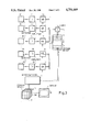
The invention will be explained in more detail below with the aid drawings which show:
FIG. 1 the mechanical arrangement for detection of the scattered radiation in schematic representation,
FIG. 2 the dependence of the radiation intensity on the scattering angle in the case of a given substance for different energies of the X-ray quanta, and
FIG. 3 a circuit for processing the signals supplied by the detectors.
In FIG. 1, 1 represents a radiation source in the form of an X-ray radiator 1 having in the radiation path a diaphragm 2 which masks a primary beam of small cross-section into its direction of propagation (pencil beam). The primary beam 3 passes through an area of examination 4 in which a body, but also a technical object, can be arranged. On the other side of the examination area 4--with respect to the radiation source--there is a detector arrangement 5 comprising a number of detectors D0, D1 . . . DN. Detector D0 is arranged in the primary beam, while the other detectors D1 . . . DN are on arcs arranged concentrically to this and are preferably annular in shape. Detectors D0, D1 . . . DN are configured in such a way that the amplitude of the electrical pulses, which are generated during the detection of an X-ray quantum, is proportional to the energy of the X-ray quantum concerned. These detectors may, for instance, be semiconductor detectors, e.g. germanium detectors or scintillation detectors, or possibly thallium-activated sodium iodide detectors. For the sake of simplicity, only five detectors are shown in the drawing (N=4). In practice, however, substantially more detectors should be used, e.g. N=30.
Detectors D1 . . . DN detect, each time, the scattered radiation which is generated in the primary beam 3 and in the examination area 4 and which leaves at a given angle with respect to the primary beam or in a small area about this angle. A definite angle therefore is allocated to each detector. If this allocation should prove too inaccurate, then it can be corrected as described in the older German patent application No. P 34 06 905, which correpsonds to European patent No. 153786, in conjunction with FIGS. 2 and 3. The angle at which the detectors detect the scattered radiation is restricted to approx. 10°; and the angle at which the scattered radiation 6 from the area of examination impinges on the most extreme detector DN is therefore approx. 10°. In the case of larger angles the proportion of the elastic scattered radiation is too small with the tube voltages used (smaller than 150 kV).
Between the body 4, which is positioned on the tabletop 7 of an examination table not illustrated in detail, and the detector arrangement 5 there is a further diaphragm 8 having an aperture dimensioned such that the scattered radiation generated in the primary beam inside the examination area 4 can just impinge on detector DN. By this means it is possible to suppress the influence of the multiply scattered radiation in the examination area 4. This multiply scattered radiation can be suppressed even better if lamellae of radiation-absorbing material, not illustrated in detail, are arranged in the form of a truncated cone between the detector arrangement 5 and below the examination area 4 in such a way that each detector can detect through these lamellae only the part of the examination area which is permeated by the primary radiation.
As indicated by the dashed line 9, the radiation source 1, the diaphragms 2 and 8 and the detector arrangement 5 are mechanically coupled to one another so that a relative movement between this arrangement and the examination area 4 is possible. For the detection of a plane examination area--as in the case of the first generation computer tomographs--the primary beam 3 is displaced laterally so that it successively passes through the plane examination area and the body is then turned, following which the primary beam is displaced in the same plane etc until each detector has detected the scattered radiation in a plurality of angular positions and displacement positions. To the extent described so far, the arrangement is largely known from the above-described article in Phys. Med. Biol., 1985, Vol. 30, No. 2, pages 183-186 and is described in the above-mentioned older patent application No. P 34 06 905.
FIG. 2 shows the pattern of the scattering intensity for one substance as a function of the scattering angle for different energies E1, E2, E3, which are related to one another as follows: E1>E2>E3. It can be seen that the intensity. i.e. the number of recorded X-ray quanta per unit time has a pronounced maximum for each energy. A substance with a different chemical composition has a different curve form for the same energy, but also with a pronounced maximum. Because of this pronounced angular dependence it is possible, therefore, to clearly distinguish between the two substances if X-ray radiation with only one energy (e.g. only E3) is used, i.e. monochromatic X-ray radiation. However, the intensity of monochromatic X-ray sources, e.g. radioisotopes, is very low which would mean long measuring times. An X-ray tube supplies X-ray radiation of much higher intensity which means that shorter measuring times result. However, X-ray tubes have a continuous (bremsstrahlung) spectrum with a maximum energy in key corresponding to the voltage at the X-ray tube (in kV). Because all the energies are represented in this spectrum right up to this limiting energy, it becomes clear that in the case of such an energy spectrum the intensity plotted against the scattering angle has only a slightly pronounced, broad maximum, as indicated by the dashed line E in FIG. 2. The corresponding curve for another substance is, in fact, not fully identical with this, but has a very broad area of overlap which means that it is difficult to distinguish two different substances from one another on the basis of the scattering angle dependence of the intensity of the elastically scattered radiation.
The invention utilizes the fact that there is a relationship
E1*sin (β1/2)=E2*sin (β2/2)=X
between the energy of the X-ray quanta and the scattering angle. In this equation, β1, β2, β3 are the scattering angles for the energies E1, E2 and E3 respectively. In the case of small angles, however, sin(β)=β can be used without great error so that
E1*β1=E2*β2μX
The product of energy and scattering angle is proportional to the so-called momentum transfer X. The curve form of the intensity of the X-ray radiation, i.e. the number of X-ray quanta per unit time, as a function of this product in the case of polychromatic radiation, is approximately the same shape as the curve of the intensity of the radiation plotted against the scattering angle in the case of monochomatic radiation. If, therefore, the product of the energy of the quantum and the scattering angle is determined for each X-ray quantum and a count is taken of the X-ray quanta which in each case exhibit the same product, then it is possible to clearly distinguish between two different substances on the basis of the different curves of the number of X-ray quanta as a function of the product.
FIG. 3 shows a circuit which appropriately processes the signals of detectors D1 . . . DN. In this circuit, each detector is allocated a channel which, in addition to the detector itself, comprises a subsequent amplifier V1, V2 . . . VN and a high-speed analog-digital converter 10 which converts the output signal of the preceding amplifier into a binary-coded digital data word.
The gains of amplifiers V1 . . . VN are proportional to the scattering angles β1 . . . βN at which the subsequent detectors detect the scattering radiation in each case. If, therefore, detector DJ, for instance, detects the scattered radiation at an angle β and detector DK detects it at an angle nβ, where n is a factor greater than 1, then the gain of the amplifier VK connected after detector DK is greater by the factor n than the gain of amplifier VJ. For this reason and because the amplitude of the output signals of the detectors is proportional to the energy of the detected X-ray quantum, signals having an amplitude, proportional to the product of the scattering angle and the energy of the X-ray quantum appear at the output of amplifiers V1 . . . VN during the detection of X-ray quanta by the corresPonding detector D1 . . . DN.
The digital-analog converters must be of a sufficiently high speed to be able to generate a signal, representing the amplitude of the output signal of amplifier V1, during each detection of an X-ray quantum by the preceding detector. They can each, for example, contain a capacitor which is charged via a peak-value rectifier by the output pulse of the preceding amplifier and which is subsequently fully discharged again by a constant current. The discharge time in this case is proportional to the product of the energy of the X-ray quantum and the gain of the preceding amplifier, i.e. to the scattering angle of the preceding detector. The discharge time is measured by means of an electronic counter register which during the discharge period counts the pulses of a constant-frequency oscillator, the start of the capacitor discharge being synchronized with the oscillator pulses. The trigger signals for the analog-digital converter 10 are derived for this from the output signals of the preceding detectors.
The outputs of the digital-analog converters 10 are coupled to the address inputs of a storage device 12. Each time one of the converters has converted a voltage pulse into a digital data word, the address corresponding to this data word in storage device 12 is called up. At the same time an adder 13 is activated which adds a 1 to the content of the storage location called up and writes the result to the same storage device. Therefore, in a defined position of the primary beam with respect to examination area, i.e. during a measurement, a count is taken at the different storage locations of storage device 12 of those X-ray quanta whose product X1, X2 . . . XM of quantum energy and scattering angle has approximately the same value in each case. Thus the converters 10, in conjunction with the storage device 12 and the adder 13, act as pulse height analyzers.
The number of groups X1 . . . XM, to which the X-ray quanta are assigned, should be approximately twice as large as the number of detectors. Because the storage device 12 and the adder 13 have to process signals from all N channels, they must have a high processing speed at high counting rates. For the situation where the processing speed is inadequate, a storage device 12 and an adder 13 can be provided for each channel or for some of the channels in each case. At the end of the measurement, only the storage contents corresponding to the same product X1, X2 or XM need to be added.
After each measurement the values stored in storage device 12 are called up and further processed in a microcomputer 14 as described, for example, in the previously mentioned German patent application No. P 34 06 905. For each measurement a correction can be made here according to the attenuation of the primary radiation by the body. This attenuation is obtained from the output signal of the detector DO which is arranged in the primary beam. If all the measurements are carried out in this way, the microcomputer can separately calculate for each product X1, X2 . . . XM the scatter distribution at the individual points of the examination plane and store these values in a storage device 15 which has a separate memory area 151 . . . 15M for each product X1 . . . XM. In order to prevent the properties of the system (e.g. the radiation spectrum of the X-ray tube, the detector characteristic etc.) from influencing the reconstruction of the distribution of the scattering cross-sections, it is necessary to divide the values obtained for the different products X1, X2 . . . XM by reference values which are obtained for the same products from calibration measurements on a calibration body of, preferably, Plexiglas. The standardized values thus obtained represent therefore the relative scattering function with respect to the reference medium. This calibration measurement need be carried out only once if the measuring conditions do not change with time. When conditions are not constant it must be repeated, e.g. every time before and/after an examination.
The images obtained in this way can be fed to a display unit 16--separated once again according to products X1 . . . XM. The pictures thus obtained show therefore for each picture point the pattern of the scattering intensity as a function of X or as a function of the scattering angle. This provides information about the chemical composition of the irradiated area.
Instead of using an amplifier with appropriately adjusted gain, the product of energy and scattering angle in the individual channels could also be obtained by means of a multiplier stage connected after the converters 10 or by designing the converters as multiplying digital-analog converters; however, the cost of this would normally be greater than that of the solution depicted in FIG. 3.

Claims (3)

What is claimed is:
1. Method for determining the spatial distribution of the scattering cross-sections for elastically scattered X-ray radiation passing through an area of examination comprising the steps of: irradiating, with a primary X-ray beam of small cross-section, the area of examination; detecting the scattered radiation leaving the examination area at different angles using a plurality of detectors; selecting the energy of the X-ray quata in the primary beam and the angular range at which the detectors detect the scattered radiation so that the proportion of elastically scattered radiation predominates therein; measuring the energy of the X-ray quanta; determining the spatial distribution of the scattering cross-section for elastically scattered X-ray radiation by ordering the detected X-ray quanta into groups; and counting the number of detected quanta in each group where each group comprises the X-ray quanta for which the product of scattering angle and energy is at least approximately the same.
2. Arrangement for implementing spatial distribution of scattering cross-sections for elastically scattered X-ray radiation comprising
an X-ray radiator providing a primary beam of X-rays;
means for masking said primary beam to form rays of small cross-section;
detectors with defined spatial positions relative to said primary beam; and
means for displacing said rays of small cross-seciton at an area of examination,
wherein the improvement comprises said detectors being configured during detection of X-ray quanta to generate pulses having an amplitude dependent on energy of the X-ray quanta;
pulse height discriminators connected after said detectors;
means for generating signals proportional to the product of measured energy and scattering angle; and
storage means for storing the number of times said product signals achieve a given value corresponding to a given area of examination.
3. Arrangement according to claim 2, wherein amplifier means are connected between each detector and a corresponding pulse height discriminator, wherein said amplifier means has a gain proportional to said scattering angle, and wherein each said detector coupled to said amplifier means detects scattered radiation for said scattering angle.
US06/884,452 1985-07-20 1986-07-11 Method for the determination of the spatial distribution of the scattering cross-sections for elastically scattered X-ray radiation and arrangement for implementation of the method Expired - Lifetime US4754469A (en)

Applications Claiming Priority (2)

Application Number Priority Date Filing Date Title
DE3526015 1985-07-20
DE19853526015 DE3526015A1 (en) 1985-07-20 1985-07-20 METHOD FOR DETERMINING THE SPATIAL DISTRIBUTION OF THE SPREAD CROSS SECTIONS FOR ELASTICALLY SCREENED X-RAY RADIATION AND ARRANGEMENT FOR IMPLEMENTING THE METHOD

Publications (1)

Publication Number Publication Date
US4754469A true US4754469A (en) 1988-06-28

Family

ID=6276310

Family Applications (1)

Application Number Title Priority Date Filing Date
US06/884,452 Expired - Lifetime US4754469A (en) 1985-07-20 1986-07-11 Method for the determination of the spatial distribution of the scattering cross-sections for elastically scattered X-ray radiation and arrangement for implementation of the method

Country Status (4)

Country Link
US (1) US4754469A (en)
EP (1) EP0209952B1 (en)
JP (1) JP2607241B2 (en)
DE (2) DE3526015A1 (en)

Cited By (33)

* Cited by examiner, † Cited by third party
Publication number Priority date Publication date Assignee Title
US4956856A (en) * 1987-10-05 1990-09-11 U.S. Philips Corporation Arrangement for examining a body comprising a radiation source
US5008911A (en) * 1988-09-22 1991-04-16 U.S. Philips Corporation X-ray quanta measuring device including diaphragm for producing conical radiation beam on object being measured
US5265144A (en) * 1991-01-19 1993-11-23 U.S. Philips Corp. X-ray apparatus
WO1998033063A1 (en) * 1997-01-24 1998-07-30 Quanta Vision Device for determining composition and structure of objects
US5863445A (en) * 1997-03-27 1999-01-26 Control Screening L.L.C. Etched coil unibody digital detector
US6054712A (en) * 1998-01-23 2000-04-25 Quanta Vision, Inc. Inspection equipment using small-angle topography in determining an object's internal structure and composition
US6175117B1 (en) 1998-01-23 2001-01-16 Quanta Vision, Inc. Tissue analysis apparatus
US6281503B1 (en) 1998-05-06 2001-08-28 Quanta Vision, Inc. Non-invasive composition analysis
GB2359719B (en) * 1999-11-13 2003-12-31 Heimann Systems Gmbh & Co A method and an apparatus for determining material of a detected article
WO2004105610A1 (en) * 2003-05-28 2004-12-09 Philips Intellectual Property & Standards Gmbh Fan-beam coherent-scatter computer tomography
US20050058242A1 (en) * 2003-09-15 2005-03-17 Peschmann Kristian R. Methods and systems for the rapid detection of concealed objects
US20060140340A1 (en) * 2003-05-27 2006-06-29 Kravis Scott D X-ray inspection system for detecting explosives and other contraband
WO2006075295A1 (en) * 2005-01-12 2006-07-20 Koninklijke Philips Electronics N.V. Computer tomography apparatus
US20070019782A1 (en) * 2003-10-14 2007-01-25 Udo Van Stevendaal Fan-beam coherent-scatter computed tomography
US20070263771A1 (en) * 2006-05-15 2007-11-15 General Electric Company Systems and methods for determining an atomic number of a substance
US20080095304A1 (en) * 2004-11-11 2008-04-24 Koninklijke Philips Electronics, N.V. Energy-Resolved Computer Tomography
US20080095305A1 (en) * 2004-11-13 2008-04-24 Koninklijke Philips Electronics, N.V. Computer Tomography Apparatus And Method For Examining An Object Of Interest
US7366282B2 (en) 2003-09-15 2008-04-29 Rapiscan Security Products, Inc. Methods and systems for rapid detection of concealed objects using fluorescence
US20080219404A1 (en) * 2007-03-08 2008-09-11 Bio-Imaging Research, Inc. Method and Apparatus to Facilitate Formation of a Two-Dimensional Image Using X-Ray Fan Beam Scatter
US20090010386A1 (en) * 2003-09-15 2009-01-08 Peschmann Kristian R Methods and Systems for Rapid Detection of Concealed Objects Using Fluorescence
US8837669B2 (en) 2003-04-25 2014-09-16 Rapiscan Systems, Inc. X-ray scanning system
US8885794B2 (en) 2003-04-25 2014-11-11 Rapiscan Systems, Inc. X-ray tomographic inspection system for the identification of specific target items
US9020095B2 (en) 2003-04-25 2015-04-28 Rapiscan Systems, Inc. X-ray scanners
US9048061B2 (en) 2005-12-16 2015-06-02 Rapiscan Systems, Inc. X-ray scanners and X-ray sources therefor
US9057679B2 (en) 2012-02-03 2015-06-16 Rapiscan Systems, Inc. Combined scatter and transmission multi-view imaging system
US9113839B2 (en) 2003-04-25 2015-08-25 Rapiscon Systems, Inc. X-ray inspection system and method
US9310323B2 (en) 2009-05-16 2016-04-12 Rapiscan Systems, Inc. Systems and methods for high-Z threat alarm resolution
US9557427B2 (en) 2014-01-08 2017-01-31 Rapiscan Systems, Inc. Thin gap chamber neutron detectors
US9791590B2 (en) 2013-01-31 2017-10-17 Rapiscan Systems, Inc. Portable security inspection system
US9823383B2 (en) 2013-01-07 2017-11-21 Rapiscan Systems, Inc. X-ray scanner with partial energy discriminating detector array
US10295483B2 (en) 2005-12-16 2019-05-21 Rapiscan Systems, Inc. Data collection, processing and storage systems for X-ray tomographic images
US10345479B2 (en) 2015-09-16 2019-07-09 Rapiscan Systems, Inc. Portable X-ray scanner
US10591424B2 (en) 2003-04-25 2020-03-17 Rapiscan Systems, Inc. X-ray tomographic inspection systems for the identification of specific target items

Families Citing this family (8)

* Cited by examiner, † Cited by third party
Publication number Priority date Publication date Assignee Title
JPH0672718B2 (en) * 1985-06-07 1994-09-14 ダイキン工業株式会社 Air conditioner wind direction controller
DE3608965A1 (en) * 1986-03-18 1987-10-01 Philips Patentverwaltung METHOD FOR DETERMINING THE SPATIAL STRUCTURE IN A LAYER OF AN EXAMINATION AREA
JPH01227555A (en) * 1988-03-08 1989-09-11 Eiji Watanabe Card type telephone set and telephone system thereof
US5007072A (en) * 1988-08-03 1991-04-09 Ion Track Instruments X-ray diffraction inspection system
GB9303518D0 (en) * 1993-02-22 1993-04-07 Merrell Dow Pharma Combinations of retroviral inhibitors
DE19510168C2 (en) * 1995-03-21 2001-09-13 Heimann Systems Gmbh & Co Method and device for determining crystalline and polycrystalline materials in an examination area
DE19954661C2 (en) * 1999-11-13 2001-12-06 Heimann Systems Gmbh & Co Device and method for adjusting a collimator
DE102004057743B4 (en) * 2004-09-08 2007-08-09 Mahlo Gmbh & Co Kg Method and device for determining the basis weight of a conveyed material sample

Citations (5)

* Cited by examiner, † Cited by third party
Publication number Priority date Publication date Assignee Title
US3936638A (en) * 1973-07-06 1976-02-03 Emi Limited Radiology
US4028554A (en) * 1974-06-07 1977-06-07 Emi Limited Radiology
US4121098A (en) * 1977-01-28 1978-10-17 Max-Planck-Gesellschaft Zur Forderung Der Wissenschaften E.V. Radiation analysis apparatus and method utilizing multi-channel pulse peak voltage discriminator
US4123654A (en) * 1975-10-03 1978-10-31 Siemens Aktiengesellschaft Method for determining the density of bodies by means of penetrating rays and apparatus for carrying out said method
EP0153786A2 (en) * 1984-02-25 1985-09-04 Philips Patentverwaltung GmbH X-ray apparatus

Family Cites Families (2)

* Cited by examiner, † Cited by third party
Publication number Priority date Publication date Assignee Title
DE2432905C3 (en) * 1974-07-09 1985-06-20 Maximilian Dr. 2430 Sierksdorf Wächtler Single-channel direction finder
JPS5822248B2 (en) * 1980-08-25 1983-05-07 富士通株式会社 liquid dispensing device

Patent Citations (5)

* Cited by examiner, † Cited by third party
Publication number Priority date Publication date Assignee Title
US3936638A (en) * 1973-07-06 1976-02-03 Emi Limited Radiology
US4028554A (en) * 1974-06-07 1977-06-07 Emi Limited Radiology
US4123654A (en) * 1975-10-03 1978-10-31 Siemens Aktiengesellschaft Method for determining the density of bodies by means of penetrating rays and apparatus for carrying out said method
US4121098A (en) * 1977-01-28 1978-10-17 Max-Planck-Gesellschaft Zur Forderung Der Wissenschaften E.V. Radiation analysis apparatus and method utilizing multi-channel pulse peak voltage discriminator
EP0153786A2 (en) * 1984-02-25 1985-09-04 Philips Patentverwaltung GmbH X-ray apparatus

Cited By (65)

* Cited by examiner, † Cited by third party
Publication number Priority date Publication date Assignee Title
US4956856A (en) * 1987-10-05 1990-09-11 U.S. Philips Corporation Arrangement for examining a body comprising a radiation source
US5008911A (en) * 1988-09-22 1991-04-16 U.S. Philips Corporation X-ray quanta measuring device including diaphragm for producing conical radiation beam on object being measured
US5265144A (en) * 1991-01-19 1993-11-23 U.S. Philips Corp. X-ray apparatus
WO1998033063A1 (en) * 1997-01-24 1998-07-30 Quanta Vision Device for determining composition and structure of objects
US5863445A (en) * 1997-03-27 1999-01-26 Control Screening L.L.C. Etched coil unibody digital detector
US6054712A (en) * 1998-01-23 2000-04-25 Quanta Vision, Inc. Inspection equipment using small-angle topography in determining an object's internal structure and composition
US6175117B1 (en) 1998-01-23 2001-01-16 Quanta Vision, Inc. Tissue analysis apparatus
US6281503B1 (en) 1998-05-06 2001-08-28 Quanta Vision, Inc. Non-invasive composition analysis
GB2359719B (en) * 1999-11-13 2003-12-31 Heimann Systems Gmbh & Co A method and an apparatus for determining material of a detected article
US9442082B2 (en) 2003-04-25 2016-09-13 Rapiscan Systems, Inc. X-ray inspection system and method
US9675306B2 (en) 2003-04-25 2017-06-13 Rapiscan Systems, Inc. X-ray scanning system
US11796711B2 (en) 2003-04-25 2023-10-24 Rapiscan Systems, Inc. Modular CT scanning system
US9020095B2 (en) 2003-04-25 2015-04-28 Rapiscan Systems, Inc. X-ray scanners
US8885794B2 (en) 2003-04-25 2014-11-11 Rapiscan Systems, Inc. X-ray tomographic inspection system for the identification of specific target items
US10901112B2 (en) 2003-04-25 2021-01-26 Rapiscan Systems, Inc. X-ray scanning system with stationary x-ray sources
US8837669B2 (en) 2003-04-25 2014-09-16 Rapiscan Systems, Inc. X-ray scanning system
US10591424B2 (en) 2003-04-25 2020-03-17 Rapiscan Systems, Inc. X-ray tomographic inspection systems for the identification of specific target items
US9113839B2 (en) 2003-04-25 2015-08-25 Rapiscon Systems, Inc. X-ray inspection system and method
US10175381B2 (en) 2003-04-25 2019-01-08 Rapiscan Systems, Inc. X-ray scanners having source points with less than a predefined variation in brightness
US9618648B2 (en) 2003-04-25 2017-04-11 Rapiscan Systems, Inc. X-ray scanners
US20060140340A1 (en) * 2003-05-27 2006-06-29 Kravis Scott D X-ray inspection system for detecting explosives and other contraband
US7092485B2 (en) 2003-05-27 2006-08-15 Control Screening, Llc X-ray inspection system for detecting explosives and other contraband
WO2004105610A1 (en) * 2003-05-28 2004-12-09 Philips Intellectual Property & Standards Gmbh Fan-beam coherent-scatter computer tomography
US7551709B2 (en) 2003-05-28 2009-06-23 Koninklijke Philips Electrions N.V. Fan-beam coherent-scatter computer tomography
US20070172026A1 (en) * 2003-05-28 2007-07-26 Jens-Peter Schlomka Fan-beam coherent-scatter computer tomography
US9915752B2 (en) 2003-08-08 2018-03-13 Rapiscan Systems, Inc. Inspection systems with two X-ray scanners in a first stage inspection system
US9042511B2 (en) 2003-08-08 2015-05-26 Rapiscan Systems, Inc. Methods and systems for the rapid detection of concealed objects
US20110228896A1 (en) * 2003-09-15 2011-09-22 Peschmann Kristian R Methods and Systems for Rapid Detection of Concealed Objects Using Fluorescence
US7856081B2 (en) 2003-09-15 2010-12-21 Rapiscan Systems, Inc. Methods and systems for rapid detection of concealed objects using fluorescence
US7366282B2 (en) 2003-09-15 2008-04-29 Rapiscan Security Products, Inc. Methods and systems for rapid detection of concealed objects using fluorescence
US8138770B2 (en) 2003-09-15 2012-03-20 Rapiscan Systems, Inc. Methods and systems for the rapid detection of concealed objects
US8428217B2 (en) 2003-09-15 2013-04-23 Rapiscan Systems, Inc. Methods and systems for rapid detection of concealed objects
US8674706B2 (en) 2003-09-15 2014-03-18 Rapiscan Systems, Inc. Methods and systems for the rapid detection of concealed objects
US20050058242A1 (en) * 2003-09-15 2005-03-17 Peschmann Kristian R. Methods and systems for the rapid detection of concealed objects
US20100085066A1 (en) * 2003-09-15 2010-04-08 Peschmann Kristian R Methods and systems for the rapid detection of concealed objects
US20090010386A1 (en) * 2003-09-15 2009-01-08 Peschmann Kristian R Methods and Systems for Rapid Detection of Concealed Objects Using Fluorescence
US9268058B2 (en) 2003-09-15 2016-02-23 Rapiscan Systems, Inc. Methods and systems for the rapid detection of concealed objects
US20070019782A1 (en) * 2003-10-14 2007-01-25 Udo Van Stevendaal Fan-beam coherent-scatter computed tomography
US20080095304A1 (en) * 2004-11-11 2008-04-24 Koninklijke Philips Electronics, N.V. Energy-Resolved Computer Tomography
US7623616B2 (en) * 2004-11-13 2009-11-24 Kkoninklijke Philips Electronics N.V. Computer tomography apparatus and method for examining an object of interest
US20080095305A1 (en) * 2004-11-13 2008-04-24 Koninklijke Philips Electronics, N.V. Computer Tomography Apparatus And Method For Examining An Object Of Interest
US7587021B2 (en) 2005-01-12 2009-09-08 Koninklijke Philips Electronics N.V. Computer tomography apparatus
WO2006075295A1 (en) * 2005-01-12 2006-07-20 Koninklijke Philips Electronics N.V. Computer tomography apparatus
US20090304145A1 (en) * 2005-01-12 2009-12-10 Koninklijke Philips Electronics, N.V. Computer tomography apparatus
US10976271B2 (en) 2005-12-16 2021-04-13 Rapiscan Systems, Inc. Stationary tomographic X-ray imaging systems for automatically sorting objects based on generated tomographic images
US9638646B2 (en) 2005-12-16 2017-05-02 Rapiscan Systems, Inc. X-ray scanners and X-ray sources therefor
US9048061B2 (en) 2005-12-16 2015-06-02 Rapiscan Systems, Inc. X-ray scanners and X-ray sources therefor
US10295483B2 (en) 2005-12-16 2019-05-21 Rapiscan Systems, Inc. Data collection, processing and storage systems for X-ray tomographic images
US7697664B2 (en) * 2006-05-15 2010-04-13 Morpho Detection, Inc. Systems and methods for determining an atomic number of a substance
US20070263771A1 (en) * 2006-05-15 2007-11-15 General Electric Company Systems and methods for determining an atomic number of a substance
US20080219404A1 (en) * 2007-03-08 2008-09-11 Bio-Imaging Research, Inc. Method and Apparatus to Facilitate Formation of a Two-Dimensional Image Using X-Ray Fan Beam Scatter
US9310323B2 (en) 2009-05-16 2016-04-12 Rapiscan Systems, Inc. Systems and methods for high-Z threat alarm resolution
US9625606B2 (en) 2009-05-16 2017-04-18 Rapiscan Systems, Inc. Systems and methods for high-Z threat alarm resolution
US9823201B2 (en) 2012-02-03 2017-11-21 Rapiscan Systems, Inc. Combined scatter and transmission multi-view imaging system
US11371948B2 (en) 2012-02-03 2022-06-28 Rapiscan Systems, Inc. Multi-view imaging system
US10746674B2 (en) 2012-02-03 2020-08-18 Rapiscan Systems, Inc. Combined scatter and transmission multi-view imaging system
US9057679B2 (en) 2012-02-03 2015-06-16 Rapiscan Systems, Inc. Combined scatter and transmission multi-view imaging system
US10353109B2 (en) 2013-01-07 2019-07-16 Rapiscan Systems, Inc. X-ray scanner with partial energy discriminating detector array
US9823383B2 (en) 2013-01-07 2017-11-21 Rapiscan Systems, Inc. X-ray scanner with partial energy discriminating detector array
US10782440B2 (en) 2013-01-07 2020-09-22 Rapiscan Systems, Inc. X-ray scanner with partial energy discriminating detector array
US10317566B2 (en) 2013-01-31 2019-06-11 Rapiscan Systems, Inc. Portable security inspection system
US9791590B2 (en) 2013-01-31 2017-10-17 Rapiscan Systems, Inc. Portable security inspection system
US11550077B2 (en) 2013-01-31 2023-01-10 Rapiscan Systems, Inc. Portable vehicle inspection portal with accompanying workstation
US9557427B2 (en) 2014-01-08 2017-01-31 Rapiscan Systems, Inc. Thin gap chamber neutron detectors
US10345479B2 (en) 2015-09-16 2019-07-09 Rapiscan Systems, Inc. Portable X-ray scanner

Also Published As

Publication number Publication date
EP0209952B1 (en) 1991-11-13
JP2607241B2 (en) 1997-05-07
JPS6222052A (en) 1987-01-30
DE3682453D1 (en) 1991-12-19
EP0209952A2 (en) 1987-01-28
DE3526015A1 (en) 1987-01-22
EP0209952A3 (en) 1989-05-03

Similar Documents

Publication Publication Date Title
US4754469A (en) Method for the determination of the spatial distribution of the scattering cross-sections for elastically scattered X-ray radiation and arrangement for implementation of the method
US5265144A (en) X-ray apparatus
US5040199A (en) Apparatus and method for analysis using x-rays
Chan et al. The validity of Monte Carlo simulation in studies of scattered radiation in diagnostic radiology
US5175756A (en) Device for detecting nitrogenous, phosphoric, chloric and oxygenous substances
EP0137487B1 (en) Energy separated quantum-counting radiography and apparatus
US10827992B2 (en) Energy-discriminating photon-counting detector and the use thereof
EP0782375A1 (en) Apparatus and method for removing scatter from an x-ray image
EP2671069B1 (en) Detection values processing apparatus
US3766383A (en) Techniques and apparatus for calibrating the kilovoltage indicator on diagnostic x-ray generators
US3404275A (en) Method of assaying and devices for the application of said method
US3056027A (en) Apparatus for measuring the thickness of a deposit
Silkwood et al. Photon counting spectral breast CT: effect of adaptive filtration on CT numbers, noise, and contrast to noise ratio
US5742660A (en) Dual energy scanning beam laminographic x-radiography
US3270204A (en) Determination of the ash content of coal by means of x-rays
JPH06121791A (en) X-ray determination device and x-ray determination method
US4458358A (en) Reference detector device for a multidetector tomodensitometer and tomodensitometer comprising such a device
US4785401A (en) Method and device for determining an energy-independent X-ray attenuation factor in a region of an object
GB2025728A (en) Correction for radiation hardening in tomography
Grant et al. X-ray diffraction microtomography
GB2084314A (en) Determining concentration by x-ray fluorescence
US4817122A (en) Apparatus for radiation analysis
FR2335854A1 (en) X:ray tomography system with collimated beam - uses two stage collimator with parallel plates and has reference level detector
MacDonald et al. The spectral sensitivity of dental X-ray films
US3154684A (en) X-ray analysis system with means to detect only the coherently scattered X-rays

Legal Events

Date Code Title Description
AS Assignment

Owner name: U.S. PHILIPS CORPORATION, 100 EAST 42ND STREET, NE

Free format text: ASSIGNMENT OF ASSIGNORS INTEREST.;ASSIGNORS:HARDING, GEOFFREY;KOSANETZKY, JOSEF-MARIA;NEITZEL, ULRICH;REEL/FRAME:004774/0123;SIGNING DATES FROM 19870814 TO 19870916

Owner name: U.S. PHILIPS CORPORATION,NEW YORK

Free format text: ASSIGNMENT OF ASSIGNORS INTEREST;ASSIGNORS:HARDING, GEOFFREY;KOSANETZKY, JOSEF-MARIA;NEITZEL, ULRICH;SIGNING DATES FROM 19870814 TO 19870916;REEL/FRAME:004774/0123

STCF Information on status: patent grant

Free format text: PATENTED CASE

FPAY Fee payment

Year of fee payment: 4

FEPP Fee payment procedure

Free format text: PAYOR NUMBER ASSIGNED (ORIGINAL EVENT CODE: ASPN); ENTITY STATUS OF PATENT OWNER: LARGE ENTITY

FPAY Fee payment

Year of fee payment: 8

FPAY Fee payment

Year of fee payment: 12