US4741015A - Universal X-ray unit - Google Patents
Universal X-ray unit Download PDFInfo
- Publication number
- US4741015A US4741015A US06/938,639 US93863986A US4741015A US 4741015 A US4741015 A US 4741015A US 93863986 A US93863986 A US 93863986A US 4741015 A US4741015 A US 4741015A
- Authority
- US
- United States
- Prior art keywords
- ring
- carrier
- ray
- axis
- suspension member
- Prior art date
- Legal status (The legal status is an assumption and is not a legal conclusion. Google has not performed a legal analysis and makes no representation as to the accuracy of the status listed.)
- Expired - Fee Related
Links
Images


Classifications
-
- A—HUMAN NECESSITIES
- A61—MEDICAL OR VETERINARY SCIENCE; HYGIENE
- A61B—DIAGNOSIS; SURGERY; IDENTIFICATION
- A61B6/00—Apparatus for radiation diagnosis, e.g. combined with radiation therapy equipment
- A61B6/44—Constructional features of apparatus for radiation diagnosis
- A61B6/4429—Constructional features of apparatus for radiation diagnosis related to the mounting of source units and detector units
- A61B6/4435—Constructional features of apparatus for radiation diagnosis related to the mounting of source units and detector units the source unit and the detector unit being coupled by a rigid structure
- A61B6/4441—Constructional features of apparatus for radiation diagnosis related to the mounting of source units and detector units the source unit and the detector unit being coupled by a rigid structure the rigid structure being a C-arm or U-arm
-
- A—HUMAN NECESSITIES
- A61—MEDICAL OR VETERINARY SCIENCE; HYGIENE
- A61B—DIAGNOSIS; SURGERY; IDENTIFICATION
- A61B6/00—Apparatus for radiation diagnosis, e.g. combined with radiation therapy equipment
- A61B6/44—Constructional features of apparatus for radiation diagnosis
- A61B6/4429—Constructional features of apparatus for radiation diagnosis related to the mounting of source units and detector units
- A61B6/4435—Constructional features of apparatus for radiation diagnosis related to the mounting of source units and detector units the source unit and the detector unit being coupled by a rigid structure
- A61B6/4447—Tiltable gantries
-
- A—HUMAN NECESSITIES
- A61—MEDICAL OR VETERINARY SCIENCE; HYGIENE
- A61B—DIAGNOSIS; SURGERY; IDENTIFICATION
- A61B6/00—Apparatus for radiation diagnosis, e.g. combined with radiation therapy equipment
- A61B6/44—Constructional features of apparatus for radiation diagnosis
- A61B6/4429—Constructional features of apparatus for radiation diagnosis related to the mounting of source units and detector units
- A61B6/4464—Constructional features of apparatus for radiation diagnosis related to the mounting of source units and detector units the source unit or the detector unit being mounted to ceiling
-
- A—HUMAN NECESSITIES
- A61—MEDICAL OR VETERINARY SCIENCE; HYGIENE
- A61N—ELECTROTHERAPY; MAGNETOTHERAPY; RADIATION THERAPY; ULTRASOUND THERAPY
- A61N5/00—Radiation therapy
- A61N5/10—X-ray therapy; Gamma-ray therapy; Particle-irradiation therapy
-
- A—HUMAN NECESSITIES
- A61—MEDICAL OR VETERINARY SCIENCE; HYGIENE
- A61N—ELECTROTHERAPY; MAGNETOTHERAPY; RADIATION THERAPY; ULTRASOUND THERAPY
- A61N5/00—Radiation therapy
- A61N5/10—X-ray therapy; Gamma-ray therapy; Particle-irradiation therapy
- A61N5/1077—Beam delivery systems
- A61N5/1081—Rotating beam systems with a specific mechanical construction, e.g. gantries
- A61N5/1082—Rotating beam systems with a specific mechanical construction, e.g. gantries having multiple beam rotation axes
Definitions
- the present invention relates to an X-ray apparatus capable of beaming in a multiplicity of directions around the body of a horizontally disposed stationary patient so that a complete, three-dimensional or sectional picture of the patient's anatomy (tomography) is made available without major changes in components of the apparatus or without having to change the position of the patient.
- X-raying of the above type intended to provide as complete a radiographic picture as possible of a human body are already known. These apparatus however can only solve the problem partially and further separate steps have to be taken in order to obtain a vision of all parts of the body. In other words, the known apparatus do not do a complete job. Additionally, the known devices are bulky and awkward to use which does not facilitate obtaining the desired information.
- the apparatus according to the invention works as if the X-raying equipment was moving along the inner surface of a hollow sphere into which the patient's body was lying still.
- the X-ray equipment is fixed to a ring which circumscribes the table and the patient.
- This ring is held on a support and is able to be driven into rotation, relative to the support, about its center.
- the apparatus also includes a fork-like suspension member which has a pair of side legs located each on one outward side of the support, the lower ends of the legs being connected with the support such as to allow the latter, and the ring it holds, to be oscillated in unison by means of a suitable motor mechanism about a horizontal axis joining the said two lower ends of the legs, this horizontal axis being further normal to the axis of rotation of the ring.
- the suspension member is in turn connected to a carrier assembly provided on a top structure of the frame of the X-ray apparatus,
- This assembly includes a carrier on which the suspension member, and hence the ring and the X-ray equipment fixed on it, are centrally and rotatably mounted for rotation about a vertical axis which intersects the axes of ring rotation and oscillation.
- FIG. 1 is a perspective view of an X-ray apparatus made according to the invention.
- FIGS. 2 and 3 are end elevation view of the apparatus of FIG. 1 showing the rotation possibility of the ring, carrying the X-ray equipment, about its center;
- FIGS. 4 and 5 are similar to FIGS. 2 and 3 but show how the ring can move transversely of the patient's table;
- FIGS. 6 and 7 are side elevation views illustrating how the X-ray ring can swing back and forth in a vertical plane
- FIGS. 8 and 9 are top views illustrating how the X-ray ring can be made to rotate about a vertical axis
- FIG. 10 is a side elevation view showing the table in position for taking radiographs from above;
- FIG. 11 is a rear elevation view of the X-ray ring and its support:
- FIG. 12 being a cross-section taken along line XII--XII of FIG. 11;
- FIG. 13 is a vertical cross-section view of taken along line XIII--XIII of FIG. 18, of the carrier assembly and of the adjoining part of the frame top structure;
- FIG. 14 is a bottom plan view of the part illustrated in FIG. 13;
- FIG. 15 is a vertical cross-sectional view taken along line XV--XV of FIG. 15, of the table supporting post in the ares of its connection to the slide rail along which the table can be displaced;
- FIG. 16 is a transverse cross-sectional view taken along line XVI--XVI of FIG. 15, of the post from beneath the power jack used for lifting the table, a portion of the latter however being shown in plan view;
- FIG. 17 is a further transverse cross-sectional view taken along line XVII--XVII of FIG. 15, of the post taken with the jacket having a portion thereof located above a slot of the post, and
- FIG. 18 is a top plan view of the carrier assembly and the adjoining parts of the frame top structure.
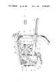
- the apparatus as generally shown in FIG. 1, comprises a ring 1 at the periphery and one face of which is secured, in any known manner, a standard X-ray equipment made up of an X-ray transmitter 3 and an X-ray receiver 5, the latter being diagonally opposite to the transmitter and connected to a television circuit with the X-ray equipment then working like a television camera.
- a standard X-ray equipment made up of an X-ray transmitter 3 and an X-ray receiver 5, the latter being diagonally opposite to the transmitter and connected to a television circuit with the X-ray equipment then working like a television camera.
- the patient lies horizontally stationary on a table 7 which, as will be seen later, can be made to move axially and vertically for the patient to be placed at various locations in the ring 1 and thus be moved with respect to the X-ray equipment.
- a forward portion 9 of the table 7 is made of X-ray non-absorbent material, such as plastic material, for use with the X-ray equipment and a rear portion 11 to be connected to a post 13 of a frame 15, more fully described hereinafter.
- the ring 1 is mounted on a support 17 for rotation about a first axis 18 (FIGS. 6, 7) intersecting the ring center C (FIG. 2), perpendicularly of the general plane of the ring 1.
- the support 17 has a back plate 19 holding the ring 1 and a pair of wings 21 solid with the back plate 19 and projecting perpendicularly therefrom and from the same face as the ring 1 (FIGS. 1, 11 and 12).
- the support 17 is connected to a suspension member 23, fork-like in outlook, which has a pair of downwardly extending side legs 25 of which the free ends are located on either outward side of the supports 17 and are connected thereto by first pivot means 27 to allow oscillation of the ring 1 (FIGS. 6 and 7) about a horizontal second axis 29 (FIG. 2) lying forwardly of the general plane of the ring 1 and intersecting its axis of rotation, or first axis 18, at right angles.
- the first pivot means 27 stands away forwardly of the general plane of the ring.
- the suspension member 23 is, in turn, supported centrally by a carrier assembly 31 (FIGS. 1 and 13) mounted on a top structure 33 of the aforesaid frame 15.
- the carrier assembly 31 includes bidirectional slide means which allow the suspension member 23 (and thus the ring 1 through the supports 17) to be moved longitudinally of the table 7, as shown in FIG. 6, and transversely thereof as shown in FIGS. 4 and 5.
- the carrier assembly 31 further includes second pivot means which allow rotation of the suspension member 23, and thus the ring 1, about a vertical axis 24 in the manner illustrated in FIGS. 8 and 9. These slide means and second pivot means are detailed hereinafter.
- the back plate 19 of the support 17 is formed with a central arcuate opening 35 having a diameter somewhat smaller but however essentially equal to that of the bore 37 of the ring 1.
- FIG. 12 shows that one face of the ring 1 lies over one face of the back plate 19; the arcuate opening 35 and the bore 37 being coaxial.
- the ring 1 is mounted for rotation about the first axis 18 of rotation (FIGS. 6 and 7) intersecting the ring center C and being perpendicular to the general plane of the ring 1; the mounting being by roller means now to be broadly described and which may be of any conventional type.
- the aforesaid roller means comprise a series of rollers 39 held by short arms 41 secured by screws 43 to the edge of the back plate 19 around the central opening 35; these rollers riding in a raceway 45 formed in the bore 37 of the ring 1. Additionally, standard roller bearings 47 may advantageously join the ring 1 to the plate 19, as clearly shown in FIG. 12.
- the ring 1 is rotated, clockwise or couterclockwise about its center C, by a first drive means which comprise toothed rack means, a drive motor and a sprocket chain.
- the rack means is preferably in the form of a series of short arcuate rack segments 49 fixed at the periphery of the ring 1 by screws 51 and spaced from one another.
- a sprocket chain 53 meshes with the rack segments 49 and with a drive sprocket 55 of an electric motor 57 fixed to the support back plate 19, as illustrated in FIG. 11.
- rotation of the drive pinion 55 by the motor 57 entrains the chain 53 which in turn rotates the ring 1 in either direction depending on the direction of rotation of the pinion 55.
- the peripheral outer edge of the ring 1 may be formed with an uninterrupted groove 59 into which the rack segments 49 are housed.
- a second drive means which comprises, on each side of the ring 1: an angled bracket 61 solid with the adjacent leg 25 of the suspension member 23 above the first pivot means 27 and projecting therefrom in the direction of the ring; an electrically actuated power jack 63 of which the free end of the axially reciprocating rod is pivoted to the adjacent wing 21 and the cylinder free end is likewise pivoted to the outer end of the bracket 61. Pivoting of the free end of the jack rods, with respect to the ring, is about an axis which lies essentially in the general plane of the ring so that the jack 63 remains vertical as clearly illustrated in FIGS. 6 and 7.
- the assembly comprise bidirectional slide means 65 and second pivot means 67.
- the slide means 65 includes a hollow carrier 69 (referred to as "second carrier” in the claims), having a releasable open top (shown in FIG. 13).
- the carrier 69 is displaceably mounted in a first set of roller races 71 formed along two opposite sides of an elongated opening 73 provided in a larger carrier 70 (referred to as “first carrier” in the claims).
- This larger carrier 70 is in turn displaceably mounted into a second set of roller races 72 perpendicular to the first one, which second set is formed along two opposite sides of an elongated opening 74 longitudinally extending in the top structure 33 (FIG. 18). Displacement is made possible in both of said openings 73 and 74 by conventional roller means.
- roller means 75 is shown in detail in FIG. 13. It comprises a set of rollers 77 which ride freely in the races 71. Displacement of the carrier 69, along the races 71 in the transversal direction, is achieved by means of one or preferably two parallel electrically actuated power jacks 79 shown at the bottom of FIG. 14 and in Fig. 18, of which the free ends of the cylinders are connected to the larger carrier 70 in any known manner. Similarly, displacement of the larger carrier 70 along the races 72 in the longitudinal direction is achieved by means of one or preferably two parallel electrically actuated jacks 80 shown in FIG. 18, of which the free ends of the cylinders are connected to the top structure 33.
- the second pivot means 67 has a cylindrical pivot heat 81 mounted on the carrier 69 through conventional roller means 83 allowing the head to rotate about the aforesaid vertical axis 24 normal to the carrier 69 (FIG. 13).
- Solid with the head 81 is a coaxial counterpin 85.
- the suspension member 23 is fixed, at its center intermediate the side legs 25, to the head 81 and pin 85 by a round connector plate 87 and screws 89.
- Rotation of the suspension member 23 is by means of second power jack means including an electrically actuated jack 91 connected, respectively, to the suspension member 23 and to one end of a bar 93 of which the other end is screwed to the bottom of the carrier 69.
- FIGS. 15, 16 and 17 show the constructional features making it possible for the table 7 to be moved both horizontally in its own plane and vertically, parallel to itself.
- the means which allow the table 7 to be moved horizontally axially comprise an eleongated horizontal hollow beam 95 extending along one side of the table 7. It is provided, on three faces, with roller guiding strips 97 for the engagement of rollers 99 rotatably mounted on threee facing walls of an essentially channel-shaped profile 101 which forms part of the table 7.
- the channel 101, rollers 99 and strips 97 thus form roller means allowing easy displacement of the table 7 along the beam 95.
- Positive movement of the channel-shaped profile 101, and thus the table 7, along the hollow beam 95 is by means of an electric motor 103 having a drive pinion 105 and being secured to and beneath the channel-shaped profile 101.
- the drive pinion 105 meshes with a toothed rack provided at the top of the lower guiding strip 97 of the beam 95. Rotation of the pinion 105 thereby causes displacement of the table 7 along the beam 95.
- the hollow beam 95 is, in turn, secured to one face of a square jacket 109 by means of screws 107; holes (not shown) being provided, for this purpose, through the wall of the hollow beam 95 opposite that through which the screws 107 are driven.
- the jacket 109 is able to slide along the post 13 by means best illustrated in FIGS. 16 and 17 and including guide strips 111, screwed each to one outer face of the post 13, and rollers 113 rotatably mounted on the jacket 109 to ride along two opposed lateral edges of the guide strips 111.
- the post 13 and the guide strip 111 facing the table 7 are formed with registering elongated slots 115, 117 (FIG. 15).
- a leg 119, solid with the jacket 109, projects through these slots 115, 117, and into the hollow post 13.
- An electrically actuated power jack 121, interconnected between the leg 119 and a bracket 123, ensures displacement of the table 7 through the beam 95 and jacket 111, when actuated; the movement being selectively up or down depending on the direction of actuation of the jack 121.
- FIGS. 2 and 3 show the possibility of rotating the ring 1 and relevant X-ray equipemnt 3, 5, fully around the patient on table 7, regardless of the inclination of the ring 1 (FIGS. 6 and 7) with respect to the horizontal plane of the table or with respect to a vertical plane transverse to the table.
- FIGS. 4 and 5 show that it is also possible to shift the ring 1 transversely of the table even if the said ring is inclined as in FIGS. 7 or 9 even if it is vertical as in FIGS. 2 to 5.
- FIGS. 15, 16 and 17 illustrate that the table 7 may be moved vertically or horizontally to occupy different positions within the ring 1.
- the operation of the apparatus of the invention can thus be compared to the working of the X-ray equipment 3 and 5 operating from the inner wall of a hollow sphere thereby providing full scanning of the body of a patient.
- Acting as a television camera the continuous viewing under various angles, of the patient's body by the X-ray equipment may be reproduced on a TV screen to which receiver 5 may be hooked.
- the apparatus of the invention may readily be adapted for the taking of still radiographs by having a suitable standard X-ray camera 125 mounted on the frame top surface 33 to slightly overhand therefrom.
- a film-carrying cassette 127 is, in this case, mounted beneath the table 7 which is of course moved below the camera 125.
- the X-ray beam 129 emitted by the tramsitter 3 intersects, at all times, the point of intersection of the horizontal oscillation axis 29 (FIG. 2), the vertical pivot axis 24 and the rotation axis of 18 of the ring 1.
Abstract
Description
Claims (15)
Priority Applications (1)
| Application Number | Priority Date | Filing Date | Title |
|---|---|---|---|
| US06/938,639 US4741015A (en) | 1986-12-05 | 1986-12-05 | Universal X-ray unit |
Applications Claiming Priority (1)
| Application Number | Priority Date | Filing Date | Title |
|---|---|---|---|
| US06/938,639 US4741015A (en) | 1986-12-05 | 1986-12-05 | Universal X-ray unit |
Publications (1)
| Publication Number | Publication Date |
|---|---|
| US4741015A true US4741015A (en) | 1988-04-26 |
Family
ID=25471721
Family Applications (1)
| Application Number | Title | Priority Date | Filing Date |
|---|---|---|---|
| US06/938,639 Expired - Fee Related US4741015A (en) | 1986-12-05 | 1986-12-05 | Universal X-ray unit |
Country Status (1)
| Country | Link |
|---|---|
| US (1) | US4741015A (en) |
Cited By (47)
| Publication number | Priority date | Publication date | Assignee | Title |
|---|---|---|---|---|
| US4856044A (en) * | 1986-07-18 | 1989-08-08 | Commissaruat A L'energie Atomique | Apparatus for the determination of the osseous mineral content |
| US4866751A (en) * | 1987-10-06 | 1989-09-12 | U.S. Philips Corporation | Radiological device of the pivoting type |
| US4921198A (en) * | 1986-12-09 | 1990-05-01 | Siemens Aktiengesellschaft | Holding mechanism for a measuring cryostat |
| US4922512A (en) * | 1988-06-03 | 1990-05-01 | General Electric Cgr Sa | Isocentric x-ray equipment stand having four axes of rotation |
| US4979196A (en) * | 1988-03-08 | 1990-12-18 | General Electric Cgr S.A. | Mammograph |
| US5048069A (en) * | 1990-03-14 | 1991-09-10 | Fischer Imaging Corporation | Dual-slide support mechanism for X-ray system components |
| US5052036A (en) * | 1990-04-02 | 1991-09-24 | Grady John K | X-ray stand with laterally inclined rotation axis |
| US5054044A (en) * | 1986-05-06 | 1991-10-01 | Thomson-Cgr | Radiology installation with a communications network |
| US5095501A (en) * | 1989-12-06 | 1992-03-10 | Kabushiki Kaisha Toshiba | X-ray image-pickup apparatus |
| US5146094A (en) * | 1991-06-07 | 1992-09-08 | Isis Inc. | Medical diagnostic nuclear camera system |
| US5148454A (en) * | 1991-08-27 | 1992-09-15 | Coffman George W | Apparatus for conducting cranial X-ray tomography and radiography |
| US5159622A (en) * | 1989-11-17 | 1992-10-27 | Kabushiki Kaisha Toshiba | X-ray fluoroscopic imaging apparatus with extended imaging set up range |
| US5262648A (en) * | 1993-02-10 | 1993-11-16 | Independent Scintillation Imaging Systems (Isis) Inc. | Medical diagnostic nuclear camera fork mounting with offset |
| WO1996006561A1 (en) * | 1994-08-30 | 1996-03-07 | David Edmund Kingston West | Self-contained apparatus for skeletal radiographic tomography |
| WO1998015382A1 (en) * | 1996-10-05 | 1998-04-16 | Axel Holle | Three dimension body movement device |
| WO1998024368A2 (en) * | 1996-12-06 | 1998-06-11 | Koninklijke Philips Electronics N.V. | Medical x-ray apparatus suitable for the formation of tomographic images |
| WO1998035613A1 (en) * | 1997-02-14 | 1998-08-20 | Koninklijke Philips Electronics N.V. | X-ray scanner with means for conventional radiography |
| WO2000074779A1 (en) * | 1999-06-09 | 2000-12-14 | Scanditronix Medical Ab | Stable rotatable radiation gantry |
| EP1075855A1 (en) * | 1999-08-11 | 2001-02-14 | Jean Valentin | Device for stereotactic radiotherapy |
| US6580777B1 (en) * | 1999-01-05 | 2003-06-17 | Hitachi Medical Corporation | X-ray CT apparatus |
| WO2003103496A1 (en) * | 2002-06-11 | 2003-12-18 | Breakaway Imaging, Llc | Cantilevered gantry apparatus for x-ray imaging |
| WO2003077763A3 (en) * | 2002-03-13 | 2004-01-08 | Breakaway Imaging Llc | Systems and methods for quasi-simultaneous multi-planar x-ray imaging |
| US20040013225A1 (en) * | 2002-03-19 | 2004-01-22 | Breakaway Imaging, Llc | Systems and methods for imaging large field-of-view objects |
| US20040022350A1 (en) * | 2002-02-15 | 2004-02-05 | Breakaway Imaging, Llc | Breakable gantry apparatus for multidimensional x-ray based imaging |
| DE10312048A1 (en) * | 2002-11-18 | 2004-05-27 | Benjamin Holch | Computer tomograph has a two part circular gantry arrangement with an inner ring housing the X-ray source and detector and an outer ring housing the power supply and a patient information system |
| US20040170254A1 (en) * | 2002-08-21 | 2004-09-02 | Breakaway Imaging, Llc | Gantry positioning apparatus for X-ray imaging |
| US20040179643A1 (en) * | 2002-08-21 | 2004-09-16 | Breakaway Imaging, Llc, Littleton, Ma | Apparatus and method for reconstruction of volumetric images in a divergent scanning computed tomography system |
| US20050061996A1 (en) * | 2002-02-28 | 2005-03-24 | Masaki Yanagisawa | Medical charged particle irradiation apparatus |
| US20050089141A1 (en) * | 2003-10-23 | 2005-04-28 | Elekta Ab (Publ) | Method and apparatus for treatment by ionizing radiation |
| US7016457B1 (en) * | 1998-12-31 | 2006-03-21 | General Electric Company | Multimode imaging system for generating high quality images |
| EP1917997A1 (en) * | 2005-08-25 | 2008-05-07 | Hui, Xiaobing | Radiotherapy device |
| US20100150304A1 (en) * | 2008-12-12 | 2010-06-17 | Fujifilm Corporation | Radiation CT imaging apparatus |
| WO2013090838A1 (en) * | 2011-12-15 | 2013-06-20 | David Chao | Medical treatment system with non-coplanar capability |
| US20140005840A1 (en) * | 2012-06-27 | 2014-01-02 | The Boeing Company | Automated Inspection of Soft-Tooled Hollow Structure |
| WO2014058775A1 (en) * | 2012-10-08 | 2014-04-17 | Carestream Health, Inc. | Extremity imaging apparatus for cone beam computed tomography |
| WO2015103564A1 (en) * | 2014-01-05 | 2015-07-09 | Xinsheng Cedric Yu | Method and system for stereotactic intensity-modulated arc therapy |
| US9266625B1 (en) * | 2012-06-27 | 2016-02-23 | The Boeing Company | System and method for scanning a wing box skin |
| US9277899B2 (en) | 2009-05-04 | 2016-03-08 | Carestream Health, Inc. | Extremity imaging apparatus for cone beam computed tomography |
| CN107495966A (en) * | 2017-07-18 | 2017-12-22 | 深圳市贝优通新能源技术开发有限公司 | A kind of suspension type intelligence NMR based on Internet of Things |
| US9949703B2 (en) | 2015-03-17 | 2018-04-24 | Carestream Health, Inc. | Extremity imaging apparatus |
| WO2018194796A1 (en) | 2017-04-21 | 2018-10-25 | Varian Medical Systems, Inc. | Dual-axis ring gantry radiotherapy systems |
| US10499861B2 (en) | 2017-09-06 | 2019-12-10 | Zap Surgical Systems, Inc. | Self-shielded, integrated-control radiosurgery system |
| GB2576337A (en) * | 2018-08-15 | 2020-02-19 | Elekta ltd | Adjustable support |
| US20200058141A1 (en) * | 2018-08-14 | 2020-02-20 | Carestream Health, Inc. | Image capture and reconstruction protocol selection system |
| EP3815742A1 (en) * | 2019-10-30 | 2021-05-05 | Ion Beam Applications S.A. | Radiotherapy apparatus comprising an imaging ring |
| US11684446B2 (en) | 2019-02-27 | 2023-06-27 | Zap Surgical Systems, Inc. | Device for radiosurgical treatment of uterine fibroids |
| US11826582B2 (en) | 2017-05-05 | 2023-11-28 | Zap Surgical Systems, Inc. | Revolving radiation collimator |
Citations (13)
| Publication number | Priority date | Publication date | Assignee | Title |
|---|---|---|---|---|
| US377124A (en) * | 1888-01-31 | Tea-kettle | ||
| US2700735A (en) * | 1948-01-26 | 1955-01-25 | Gen Electric | Tiltable cantilever X-ray table |
| US2818510A (en) * | 1953-07-23 | 1957-12-31 | Philips Corp | Diagnostic x-ray device |
| US3281598A (en) * | 1965-11-19 | 1966-10-25 | Picker X Ray Corp Waite Mfg | Overhead support for a vertically and rotatably movable x-ray tube support arm and cooperating tiltable x-ray table |
| US3588499A (en) * | 1967-06-15 | 1971-06-28 | Ca Atomic Energy Ltd | Radiation therapy machine with a rotatable hypesbaric chamber having a radiation source mounted therein |
| US3783251A (en) * | 1970-11-27 | 1974-01-01 | Varian Associates | Computer assisted radiation therapy machine |
| US3803417A (en) * | 1971-05-13 | 1974-04-09 | Philips Corp | X-ray apparatus for heart catheterization and other procedures |
| US3833813A (en) * | 1972-09-25 | 1974-09-03 | Philips Corp | Device for examining a patient, in particular by means of x-rays |
| US4020348A (en) * | 1975-05-12 | 1977-04-26 | G. D. Searle & Co. | Gantry scanning camera |
| US4187429A (en) * | 1977-05-13 | 1980-02-05 | Hitachi Medical Corporation | Scanning apparatus for cross-sectional inspection equipment |
| US4298801A (en) * | 1980-01-17 | 1981-11-03 | General Electric Company | L-U Arm handle assembly |
| US4481656A (en) * | 1981-05-11 | 1984-11-06 | U.S. Philips Corporation | Medical apparatus |
| US4501011A (en) * | 1982-09-22 | 1985-02-19 | General Electric Company | Angulating lateral fluoroscopic suspension |
-
1986
- 1986-12-05 US US06/938,639 patent/US4741015A/en not_active Expired - Fee Related
Patent Citations (13)
| Publication number | Priority date | Publication date | Assignee | Title |
|---|---|---|---|---|
| US377124A (en) * | 1888-01-31 | Tea-kettle | ||
| US2700735A (en) * | 1948-01-26 | 1955-01-25 | Gen Electric | Tiltable cantilever X-ray table |
| US2818510A (en) * | 1953-07-23 | 1957-12-31 | Philips Corp | Diagnostic x-ray device |
| US3281598A (en) * | 1965-11-19 | 1966-10-25 | Picker X Ray Corp Waite Mfg | Overhead support for a vertically and rotatably movable x-ray tube support arm and cooperating tiltable x-ray table |
| US3588499A (en) * | 1967-06-15 | 1971-06-28 | Ca Atomic Energy Ltd | Radiation therapy machine with a rotatable hypesbaric chamber having a radiation source mounted therein |
| US3783251A (en) * | 1970-11-27 | 1974-01-01 | Varian Associates | Computer assisted radiation therapy machine |
| US3803417A (en) * | 1971-05-13 | 1974-04-09 | Philips Corp | X-ray apparatus for heart catheterization and other procedures |
| US3833813A (en) * | 1972-09-25 | 1974-09-03 | Philips Corp | Device for examining a patient, in particular by means of x-rays |
| US4020348A (en) * | 1975-05-12 | 1977-04-26 | G. D. Searle & Co. | Gantry scanning camera |
| US4187429A (en) * | 1977-05-13 | 1980-02-05 | Hitachi Medical Corporation | Scanning apparatus for cross-sectional inspection equipment |
| US4298801A (en) * | 1980-01-17 | 1981-11-03 | General Electric Company | L-U Arm handle assembly |
| US4481656A (en) * | 1981-05-11 | 1984-11-06 | U.S. Philips Corporation | Medical apparatus |
| US4501011A (en) * | 1982-09-22 | 1985-02-19 | General Electric Company | Angulating lateral fluoroscopic suspension |
Cited By (105)
| Publication number | Priority date | Publication date | Assignee | Title |
|---|---|---|---|---|
| US5054044A (en) * | 1986-05-06 | 1991-10-01 | Thomson-Cgr | Radiology installation with a communications network |
| US4856044A (en) * | 1986-07-18 | 1989-08-08 | Commissaruat A L'energie Atomique | Apparatus for the determination of the osseous mineral content |
| US4921198A (en) * | 1986-12-09 | 1990-05-01 | Siemens Aktiengesellschaft | Holding mechanism for a measuring cryostat |
| US4866751A (en) * | 1987-10-06 | 1989-09-12 | U.S. Philips Corporation | Radiological device of the pivoting type |
| US4979196A (en) * | 1988-03-08 | 1990-12-18 | General Electric Cgr S.A. | Mammograph |
| US4922512A (en) * | 1988-06-03 | 1990-05-01 | General Electric Cgr Sa | Isocentric x-ray equipment stand having four axes of rotation |
| US5159622A (en) * | 1989-11-17 | 1992-10-27 | Kabushiki Kaisha Toshiba | X-ray fluoroscopic imaging apparatus with extended imaging set up range |
| US5095501A (en) * | 1989-12-06 | 1992-03-10 | Kabushiki Kaisha Toshiba | X-ray image-pickup apparatus |
| US5048069A (en) * | 1990-03-14 | 1991-09-10 | Fischer Imaging Corporation | Dual-slide support mechanism for X-ray system components |
| US5052036A (en) * | 1990-04-02 | 1991-09-24 | Grady John K | X-ray stand with laterally inclined rotation axis |
| US5146094A (en) * | 1991-06-07 | 1992-09-08 | Isis Inc. | Medical diagnostic nuclear camera system |
| US5148454A (en) * | 1991-08-27 | 1992-09-15 | Coffman George W | Apparatus for conducting cranial X-ray tomography and radiography |
| US5262648A (en) * | 1993-02-10 | 1993-11-16 | Independent Scintillation Imaging Systems (Isis) Inc. | Medical diagnostic nuclear camera fork mounting with offset |
| WO1996006561A1 (en) * | 1994-08-30 | 1996-03-07 | David Edmund Kingston West | Self-contained apparatus for skeletal radiographic tomography |
| WO1998015382A1 (en) * | 1996-10-05 | 1998-04-16 | Axel Holle | Three dimension body movement device |
| US6331152B1 (en) | 1996-10-05 | 2001-12-18 | Axel Holle | Three dimension body movement device |
| WO1998024368A3 (en) * | 1996-12-06 | 1998-08-20 | Philips Electronics Nv | Medical x-ray apparatus suitable for the formation of tomographic images |
| WO1998024368A2 (en) * | 1996-12-06 | 1998-06-11 | Koninklijke Philips Electronics N.V. | Medical x-ray apparatus suitable for the formation of tomographic images |
| WO1998035613A1 (en) * | 1997-02-14 | 1998-08-20 | Koninklijke Philips Electronics N.V. | X-ray scanner with means for conventional radiography |
| US7016457B1 (en) * | 1998-12-31 | 2006-03-21 | General Electric Company | Multimode imaging system for generating high quality images |
| US6580777B1 (en) * | 1999-01-05 | 2003-06-17 | Hitachi Medical Corporation | X-ray CT apparatus |
| WO2000074779A1 (en) * | 1999-06-09 | 2000-12-14 | Scanditronix Medical Ab | Stable rotatable radiation gantry |
| US6969194B1 (en) * | 1999-06-09 | 2005-11-29 | Pencilbeam Technologies Ab | Stable rotatable radiation gantry |
| WO2001012262A1 (en) * | 1999-08-11 | 2001-02-22 | Jean Valentin | Device for stereotactic radiotherapy |
| EP1075855A1 (en) * | 1999-08-11 | 2001-02-14 | Jean Valentin | Device for stereotactic radiotherapy |
| US6940941B2 (en) | 2002-02-15 | 2005-09-06 | Breakaway Imaging, Llc | Breakable gantry apparatus for multidimensional x-ray based imaging |
| US20040022350A1 (en) * | 2002-02-15 | 2004-02-05 | Breakaway Imaging, Llc | Breakable gantry apparatus for multidimensional x-ray based imaging |
| US20050061996A1 (en) * | 2002-02-28 | 2005-03-24 | Masaki Yanagisawa | Medical charged particle irradiation apparatus |
| US20040013239A1 (en) * | 2002-03-13 | 2004-01-22 | Breakaway Imaging, Llc | Systems and methods for quasi-simultaneous multi-planar x-ray imaging |
| WO2003077763A3 (en) * | 2002-03-13 | 2004-01-08 | Breakaway Imaging Llc | Systems and methods for quasi-simultaneous multi-planar x-ray imaging |
| CN100398066C (en) * | 2002-03-13 | 2008-07-02 | 分离成像有限责任公司 | Systems and methods for quasi-simultaneous multi-planar X-ray imaging |
| US20080013691A1 (en) * | 2002-03-13 | 2008-01-17 | Gregerson Eugene A | Systems and methods for quasi-simultaneous multi-planar x-ray imaging |
| US8746973B2 (en) * | 2002-03-13 | 2014-06-10 | Medtronic Navigation, Inc. | Systems and methods for quasi-simultaneous multi-planar x-ray imaging |
| US7188998B2 (en) * | 2002-03-13 | 2007-03-13 | Breakaway Imaging, Llc | Systems and methods for quasi-simultaneous multi-planar x-ray imaging |
| JP2011167564A (en) * | 2002-03-13 | 2011-09-01 | Medtronic Navigation Inc | System and method for quasi-simultaneous multi-planar x-ray imaging |
| JP2005519688A (en) * | 2002-03-13 | 2005-07-07 | ブレークアウェイ・イメージング・エルエルシー | Pseudo simultaneous multiplanar X-ray imaging system and method |
| US20070086566A1 (en) * | 2002-03-19 | 2007-04-19 | Gregerson Eugene A | Systems and methods for imaging large field-of-view objects |
| US9398886B2 (en) | 2002-03-19 | 2016-07-26 | Medtronic Navigation, Inc. | Systems and methods for imaging large field-of-view objects |
| US9724058B2 (en) | 2002-03-19 | 2017-08-08 | Medtronic Navigation, Inc. | Systems and methods for imaging large field-of-view objects |
| US7661881B2 (en) | 2002-03-19 | 2010-02-16 | Medtronic Navigation, Inc. | Systems and methods for imaging large field-of-view objects |
| US20100142671A1 (en) * | 2002-03-19 | 2010-06-10 | Gregerson Eugene A | Systems and methods for imaging large field-of-view objects |
| US8678647B2 (en) | 2002-03-19 | 2014-03-25 | Medtronic Navigation, Inc. | Systems and methods for imaging large field-of-view objects |
| US7108421B2 (en) | 2002-03-19 | 2006-09-19 | Breakaway Imaging, Llc | Systems and methods for imaging large field-of-view objects |
| US20040013225A1 (en) * | 2002-03-19 | 2004-01-22 | Breakaway Imaging, Llc | Systems and methods for imaging large field-of-view objects |
| USRE49349E1 (en) | 2002-03-19 | 2022-12-27 | Medtronic Navigation, Inc. | Systems and methods for imaging large field-of-view objects |
| US8308361B2 (en) | 2002-06-11 | 2012-11-13 | Medtronic Navigation, Inc. | Cantilevered gantry apparatus for X-ray imaging |
| US7905659B2 (en) | 2002-06-11 | 2011-03-15 | Medtronic Navigation, Inc. | Cantilevered gantry apparatus for x-ray imaging |
| US20110200175A1 (en) * | 2002-06-11 | 2011-08-18 | Gregerson Eugene A | Cantilevered gantry apparatus for x-ray imaging |
| US20030235266A1 (en) * | 2002-06-11 | 2003-12-25 | Breakaway Imaging, Llc | Cantilevered gantry apparatus for x-ray imaging |
| WO2003103496A1 (en) * | 2002-06-11 | 2003-12-18 | Breakaway Imaging, Llc | Cantilevered gantry apparatus for x-ray imaging |
| US7001045B2 (en) | 2002-06-11 | 2006-02-21 | Breakaway Imaging, Llc | Cantilevered gantry apparatus for x-ray imaging |
| US20080212743A1 (en) * | 2002-06-11 | 2008-09-04 | Gregerson Eugene A | Cantilevered gantry apparatus for x-ray imaging |
| US7490982B2 (en) | 2002-08-21 | 2009-02-17 | Medtronic Navigation, Inc. | Gantry positioning apparatus for x-ray imaging |
| US7106825B2 (en) | 2002-08-21 | 2006-09-12 | Breakaway Imaging, Llc | Apparatus and method for reconstruction of volumetric images in a divergent scanning computed tomography system |
| US20040179643A1 (en) * | 2002-08-21 | 2004-09-16 | Breakaway Imaging, Llc, Littleton, Ma | Apparatus and method for reconstruction of volumetric images in a divergent scanning computed tomography system |
| US20040170254A1 (en) * | 2002-08-21 | 2004-09-02 | Breakaway Imaging, Llc | Gantry positioning apparatus for X-ray imaging |
| US7338207B2 (en) | 2002-08-21 | 2008-03-04 | Medtronic Navigation, Inc. | Gantry positioning apparatus for X-ray imaging |
| US20060120511A1 (en) * | 2002-08-21 | 2006-06-08 | Gregerson Eugene A | Gantry positioning apparatus for x-ray imaging |
| US7903779B2 (en) | 2002-08-21 | 2011-03-08 | Medtronic Navigation, Inc. | Apparatus and method for reconstruction of volumetric images in a divergent scanning computed tomography system |
| US20070104308A1 (en) * | 2002-08-21 | 2007-05-10 | Breakaway Imaging, Llc | Apparatus and method for reconstruction of volumetric images in a divergent scanning computed tomography system |
| US20110135054A1 (en) * | 2002-08-21 | 2011-06-09 | Gregerson Eugene A | Apparatus and method for reconstruction of volumetric images in a divergent scanning computed tomography system |
| US7965811B1 (en) | 2002-08-21 | 2011-06-21 | Medtronic Navigation, Inc. | Apparatus and method for reconstruction of volumetric images in a divergent scanning computed tomography system |
| DE10312048A1 (en) * | 2002-11-18 | 2004-05-27 | Benjamin Holch | Computer tomograph has a two part circular gantry arrangement with an inner ring housing the X-ray source and detector and an outer ring housing the power supply and a patient information system |
| DE10312048B4 (en) * | 2002-11-18 | 2005-01-20 | Benjamin Holch | CT Scanner |
| AU2004285332B2 (en) * | 2003-10-23 | 2009-07-30 | Elekta Ab (Publ) | Apparatus for treatment by ionising radiation |
| US20050089141A1 (en) * | 2003-10-23 | 2005-04-28 | Elekta Ab (Publ) | Method and apparatus for treatment by ionizing radiation |
| US7295648B2 (en) * | 2003-10-23 | 2007-11-13 | Elektra Ab (Publ) | Method and apparatus for treatment by ionizing radiation |
| EP1917997A4 (en) * | 2005-08-25 | 2010-03-17 | Hui Xiaobing | Radiotherapy device |
| EP1917997A1 (en) * | 2005-08-25 | 2008-05-07 | Hui, Xiaobing | Radiotherapy device |
| US20100150304A1 (en) * | 2008-12-12 | 2010-06-17 | Fujifilm Corporation | Radiation CT imaging apparatus |
| US10307115B2 (en) | 2009-05-04 | 2019-06-04 | Carestream Health, Inc. | Extremity imaging apparatus for cone beam computed tomography |
| US9770214B2 (en) | 2009-05-04 | 2017-09-26 | Carestream Health, Inc. | Extremity imaging apparatus for cone beam computed tomography |
| US10010295B2 (en) | 2009-05-04 | 2018-07-03 | Carestream Health, Inc. | Extremity imaging apparatus for cone beam computed tomography |
| US9597044B2 (en) | 2009-05-04 | 2017-03-21 | Carestream Health, Inc. | Extremity imaging apparatus for cone beam computed tomography |
| US9277899B2 (en) | 2009-05-04 | 2016-03-08 | Carestream Health, Inc. | Extremity imaging apparatus for cone beam computed tomography |
| WO2013090838A1 (en) * | 2011-12-15 | 2013-06-20 | David Chao | Medical treatment system with non-coplanar capability |
| US9010684B2 (en) * | 2012-06-27 | 2015-04-21 | The Boeing Company | Automated inspection of soft-tooled hollow structure |
| US9266625B1 (en) * | 2012-06-27 | 2016-02-23 | The Boeing Company | System and method for scanning a wing box skin |
| US20140005840A1 (en) * | 2012-06-27 | 2014-01-02 | The Boeing Company | Automated Inspection of Soft-Tooled Hollow Structure |
| US10405812B2 (en) | 2012-10-08 | 2019-09-10 | Carestream Health, Inc. | Extremity imaging apparatus for cone beam computed tomography |
| US9717467B2 (en) | 2012-10-08 | 2017-08-01 | Carestream Health, Inc. | Extremity imaging apparatus for cone beam computed tomography |
| CN104968273A (en) * | 2012-10-08 | 2015-10-07 | 卡尔斯特里姆保健公司 | Extremity imaging apparatus for cone beam computed tomography |
| US9907516B2 (en) | 2012-10-08 | 2018-03-06 | Carestream Health, Inc. | Extremity imaging apparatus for cone beam computed tomography |
| CN104837408A (en) * | 2012-10-08 | 2015-08-12 | 卡尔斯特里姆保健公司 | Extremity imaging apparatus for cone beam computed tomography |
| US10034641B2 (en) | 2012-10-08 | 2018-07-31 | Carestream Health, Inc. | Extremity imaging apparatus for cone beam computed tomography |
| WO2014058775A1 (en) * | 2012-10-08 | 2014-04-17 | Carestream Health, Inc. | Extremity imaging apparatus for cone beam computed tomography |
| WO2015103564A1 (en) * | 2014-01-05 | 2015-07-09 | Xinsheng Cedric Yu | Method and system for stereotactic intensity-modulated arc therapy |
| US9949703B2 (en) | 2015-03-17 | 2018-04-24 | Carestream Health, Inc. | Extremity imaging apparatus |
| WO2018194796A1 (en) | 2017-04-21 | 2018-10-25 | Varian Medical Systems, Inc. | Dual-axis ring gantry radiotherapy systems |
| EP3612273A4 (en) * | 2017-04-21 | 2020-09-02 | Varian Medical Systems, Inc. | Dual-axis ring gantry radiotherapy systems |
| US11826582B2 (en) | 2017-05-05 | 2023-11-28 | Zap Surgical Systems, Inc. | Revolving radiation collimator |
| CN107495966A (en) * | 2017-07-18 | 2017-12-22 | 深圳市贝优通新能源技术开发有限公司 | A kind of suspension type intelligence NMR based on Internet of Things |
| US10499861B2 (en) | 2017-09-06 | 2019-12-10 | Zap Surgical Systems, Inc. | Self-shielded, integrated-control radiosurgery system |
| US11844637B2 (en) | 2017-09-06 | 2023-12-19 | Zap Surgical Systems, Inc. | Therapeutic radiation beam detector for radiation treatment systems |
| US20200058141A1 (en) * | 2018-08-14 | 2020-02-20 | Carestream Health, Inc. | Image capture and reconstruction protocol selection system |
| GB2576337A (en) * | 2018-08-15 | 2020-02-19 | Elekta ltd | Adjustable support |
| US20210161491A1 (en) * | 2018-08-15 | 2021-06-03 | Anthony Westwood | Adjustable support |
| US11813096B2 (en) * | 2018-08-15 | 2023-11-14 | Elekta Limited | Adjustable support |
| US11684446B2 (en) | 2019-02-27 | 2023-06-27 | Zap Surgical Systems, Inc. | Device for radiosurgical treatment of uterine fibroids |
| CN114616030A (en) * | 2019-10-30 | 2022-06-10 | 离子束应用股份有限公司 | Radiotherapy apparatus comprising an imaging ring |
| JP2022549019A (en) * | 2019-10-30 | 2022-11-22 | イオン ビーム アプリケーションズ ソシエテ アノニム | Radiation therapy device including an imaging ring |
| US11511135B2 (en) | 2019-10-30 | 2022-11-29 | Ion Beam Applications | Radiotherapy apparatus comprising an imaging ring |
| CN114616030B (en) * | 2019-10-30 | 2023-07-25 | 离子束应用股份有限公司 | Radiation therapy apparatus including imaging ring |
| WO2021084045A1 (en) | 2019-10-30 | 2021-05-06 | Ion Beam Applications | Radiotherapy apparatus comprising an imaging ring |
| EP3815742A1 (en) * | 2019-10-30 | 2021-05-05 | Ion Beam Applications S.A. | Radiotherapy apparatus comprising an imaging ring |
Similar Documents
| Publication | Publication Date | Title |
|---|---|---|
| US4741015A (en) | Universal X-ray unit | |
| US4501011A (en) | Angulating lateral fluoroscopic suspension | |
| EP0632995B1 (en) | Dental X-ray diagnostic device | |
| US3737660A (en) | Apparatus for taking tomograms of parabolically curved objects | |
| JPH0117690B2 (en) | ||
| DE19844106A1 (en) | X-ray system to produces panoramic tomograms | |
| US6095685A (en) | X-ray radioscopic apparatus | |
| EP0632994B1 (en) | X-ray diagnostic device for producing X-rays of body parts of a patient | |
| DE19921280C1 (en) | X=ray diagnostic apparatus with computer tomography recording device | |
| KR101232757B1 (en) | Medical radiography system | |
| DE60207625T2 (en) | X-ray device for fluoroscopy and radiography | |
| CN210408449U (en) | Novel integrated cone beam CT | |
| CA1252580A (en) | Universal x-ray unit | |
| US3831032A (en) | Tomographic and x-ray photographic diagnostic apparatus for pediatric examination | |
| JPH0998971A (en) | Medical use x-ray photographing equipment | |
| EP0114054A2 (en) | X-ray tomography table having a virtual fulcrum arm pivot | |
| JPH0117692B2 (en) | ||
| US4550421A (en) | Radiology table for exposures with variable tilting angle and source-patient distance and for tomography | |
| US3934140A (en) | X-ray diagnostic apparatus in particular for examining the injured | |
| CN216257144U (en) | Digital X-ray photographic system suitable for human body or animal | |
| SU709060A1 (en) | Tomography adaptor | |
| JPS61276544A (en) | Tomographic apparatus | |
| KR20120090290A (en) | Medical radiography system | |
| JPH11104123A (en) | X-ray radiographic device | |
| JP3233423B2 (en) | X-ray CT system |
Legal Events
| Date | Code | Title | Description |
|---|---|---|---|
| AS | Assignment |
Owner name: B.C. MEDICAL COMPAGNIE LIMITEE, 1303 DE MAISHONNEU Free format text: ASSIGNMENT OF ASSIGNORS INTEREST.;ASSIGNOR:CHARRIER, PIERRE;REEL/FRAME:004641/0190 Effective date: 19861110 Owner name: B.C. MEDICAL COMPAGNIE LIMITEE, CANADA Free format text: ASSIGNMENT OF ASSIGNORS INTEREST;ASSIGNOR:CHARRIER, PIERRE;REEL/FRAME:004641/0190 Effective date: 19861110 |
|
| FEPP | Fee payment procedure |
Free format text: PAYOR NUMBER ASSIGNED (ORIGINAL EVENT CODE: ASPN); ENTITY STATUS OF PATENT OWNER: SMALL ENTITY |
|
| REMI | Maintenance fee reminder mailed | ||
| LAPS | Lapse for failure to pay maintenance fees | ||
| FP | Lapsed due to failure to pay maintenance fee |
Effective date: 19920426 |
|
| STCH | Information on status: patent discontinuation |
Free format text: PATENT EXPIRED DUE TO NONPAYMENT OF MAINTENANCE FEES UNDER 37 CFR 1.362 |