US4652759A - Counterbalanced radiation detection system - Google Patents
Counterbalanced radiation detection system Download PDFInfo
- Publication number
- US4652759A US4652759A US06/630,903 US63090384A US4652759A US 4652759 A US4652759 A US 4652759A US 63090384 A US63090384 A US 63090384A US 4652759 A US4652759 A US 4652759A
- Authority
- US
- United States
- Prior art keywords
- rod
- radiation detector
- gamma camera
- stand
- trunnion
- Prior art date
- Legal status (The legal status is an assumption and is not a legal conclusion. Google has not performed a legal analysis and makes no representation as to the accuracy of the status listed.)
- Expired - Fee Related
Links
Images

Classifications
-
- A—HUMAN NECESSITIES
- A61—MEDICAL OR VETERINARY SCIENCE; HYGIENE
- A61B—DIAGNOSIS; SURGERY; IDENTIFICATION
- A61B6/00—Apparatus for radiation diagnosis, e.g. combined with radiation therapy equipment
- A61B6/44—Constructional features of apparatus for radiation diagnosis
- A61B6/4429—Constructional features of apparatus for radiation diagnosis related to the mounting of source units and detector units
- A61B6/447—Constructional features of apparatus for radiation diagnosis related to the mounting of source units and detector units the source unit or the detector unit being mounted to counterpoise or springs
-
- A—HUMAN NECESSITIES
- A61—MEDICAL OR VETERINARY SCIENCE; HYGIENE
- A61B—DIAGNOSIS; SURGERY; IDENTIFICATION
- A61B6/00—Apparatus for radiation diagnosis, e.g. combined with radiation therapy equipment
- A61B6/42—Apparatus for radiation diagnosis, e.g. combined with radiation therapy equipment with arrangements for detecting radiation specially adapted for radiation diagnosis
- A61B6/4208—Apparatus for radiation diagnosis, e.g. combined with radiation therapy equipment with arrangements for detecting radiation specially adapted for radiation diagnosis characterised by using a particular type of detector
- A61B6/4258—Apparatus for radiation diagnosis, e.g. combined with radiation therapy equipment with arrangements for detecting radiation specially adapted for radiation diagnosis characterised by using a particular type of detector for detecting non x-ray radiation, e.g. gamma radiation
-
- G—PHYSICS
- G01—MEASURING; TESTING
- G01T—MEASUREMENT OF NUCLEAR OR X-RADIATION
- G01T1/00—Measuring X-radiation, gamma radiation, corpuscular radiation, or cosmic radiation
- G01T1/16—Measuring radiation intensity
- G01T1/161—Applications in the field of nuclear medicine, e.g. in vivo counting
- G01T1/164—Scintigraphy
- G01T1/166—Scintigraphy involving relative movement between detector and subject
-
- G—PHYSICS
- G01—MEASURING; TESTING
- G01T—MEASUREMENT OF NUCLEAR OR X-RADIATION
- G01T1/00—Measuring X-radiation, gamma radiation, corpuscular radiation, or cosmic radiation
- G01T1/29—Measurement performed on radiation beams, e.g. position or section of the beam; Measurement of spatial distribution of radiation
- G01T1/2914—Measurement of spatial distribution of radiation
- G01T1/2985—In depth localisation, e.g. using positron emitters; Tomographic imaging (longitudinal and transverse section imaging; apparatus for radiation diagnosis sequentially in different planes, steroscopic radiation diagnosis)
-
- A—HUMAN NECESSITIES
- A61—MEDICAL OR VETERINARY SCIENCE; HYGIENE
- A61B—DIAGNOSIS; SURGERY; IDENTIFICATION
- A61B6/00—Apparatus for radiation diagnosis, e.g. combined with radiation therapy equipment
- A61B6/02—Devices for diagnosis sequentially in different planes; Stereoscopic radiation diagnosis
- A61B6/03—Computerised tomographs
- A61B6/037—Emission tomography
Definitions
- the invention relates to a counterbalanced radiation detection system.
- the invention relates to a rotational counterbalanced gamma camera system.
- the brochure "ROTA CAMERA A versatile gamma camera system for SPECT and conventional imaging" of Siemens Gammasonics, Inc., 2000 Nuclear Drive, Des Plaines, Ill. 60018, No. MG/5700-006-121B INT 4M 11/82 illustrates a rotational counterbalanced gamma camera system.
- the system comprises a base and a gantry connected with the base. It further comprises a first and second gamma camera heads which are both tiltably connected with the gantry. During rotating of the gantry both camera heads describe an orbit about a patient under investigation. The tilting angle of each camera head is a measure for the radius of the orbit.
- Each gamma camera head is counterbalanced by a separate counterweight, such as of lead.
- U.S. Pat. No. 4,057,727 (Muehllehner et al.) describes a position imaging system having a gantry and two camera heads which are positioned on opposite sides of the circumference of the gantry. During rotation of the gantry one camera head always counterbalances the other one while both camera heads are rotating on an orbit about a patient. However, the camera heads are not tiltable.
- U.S. Pat. No. 3,797,819 depicts a supporting table for patients comprising a table plate and a lever mechanism for positioning the table plate in different heights.
- an improved counterbalanced radiation detection system which comprises:
- the torque transforming means according to this invention counterbalance the tiltable first and second radiation detectors against each other. No additional counterweight for each radiation detector is necessary.
- a counterbalanced gamma camera system which comprises:
- a torque transforming means connected between the first and second gamma camera head for transforming the torque created by one of the gamma camera heads opposite to the torque created by the other gamma camera head.
- a rotational counterbalanced camera system which comprises:
- a torque transforming means connected between the first and second gamma camera head for transforming the torque created by one of the gamma camera heads opposite to the torque created by the other gamma camera head.
- FIG. 1 is an overview of a rotational counterbalanced gamma camera system according to this invention
- FIG. 2 is a side view of a system according to FIG. 1 showing in a schematic diagram a torque transforming mechanism for the first and second camera heads;
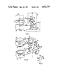
- FIG. 3 is the torque transforming mechanism of FIG. 2 in a perspective view
- FIG. 4 is a more detailed structure of a trunnion of the torque transforming mechanism.
- the rotational counterbalanced gamma camera system of FIG. 1 comprises a stand 8 having a base 10 and a gantry 12 mounted vertically on the base 10.
- the central opening 14 of the gantry 12 contains a ring structure 16 which is rotatable about a horizontal axis 18.
- a table top 20 for carrying a patient 22 extends along the horizontal axis 18 through the central opening 24 of the ring structure 16.
- a first and second gamma camera heads 26 and 28 are accommodated on the ring structure 16 by means of first, second, third and fourth cantilevers 30, 32, 34 and 36, respectively.
- the camera heads 26 and 28 are preferably ZLC camera heads.
- SPECT single photon emission computed tomography
- the dual camera heads 26 and 28 double the sensitivity of the system and thus improve image statistics for a given counting rate.
- they can be used in conventional procedures.
- SPECT reconstructive imaging the camera heads 26 and 28 are jointly rotated around the patient 22.
- the camera heads 26 and 28 track the center line of rotation precisely as they are rotated around the patient 22. Accurate information regarding the positions of the camera heads are continuously transmitted for imaging reconstruction.
- the first and second gamma camera heads 26, 28 each comprise a first and second collimators 38 and 40, respectively.
- the rotational counterbalanced gamma camera system comprises a torque transforming mechanism 50 which is connected between the first, second, third and fourth cantilevers 30, 32, 34 and 36, for transforming the torque created by one of the gamma camera heads opposite to the torque created by the other gamma camera head.
- the torque transforming mechanism 50 includes a rod mechanism.
- the rod mechanism comprises a first rod mechanism portion containing a first rod 52 and a second rod 54.
- the rod mechanism also has a second rod mechanism portion including a third rod 56 and a fourth rod 58.
- the rod mechanism contains a third rod mechanism portion which comprises a fifth rod 60 and a sixth rod 62.
- the first, second, third and fourth cantilevers 30, 32, 34, 36 are tiltably mounted in the interior of the ring structure 16 of the gantry 12 by means of a first, second, third and fourth trunnions 64, 66, 68 and 70.
- the first rod 52 is connected with the first cantilever 30 by means of the first trunnion 64 under a first angle ⁇ .
- the second rod 54 is connected with the second cantilever 32 by means of the second trunnion 66 under the first angle ⁇ .
- the third rod 56 is connected with the third cantilever 34 via the third trunnion 68 under a second angle ⁇ .
- the fourth rod 58 is connected with the fourth cantilever 36 via the fourth trunnion 70 under the second angle ⁇ .
- the rod mechanism also comprises a fifth, sixth, seventh and eighth trunnions 72, 74, 76 and 78.
- the fifth rod 60 is connected at one end with the first rod 52 by means of the fifth trunnion 72 and at its other end with the third rod 56 by means of the sixth trunnion 74 as illustrated in FIG. 3.
- the sixth rod 62 is connected at its one end with the second rod 54 by means of the seventh trunnion 76 and at its other end with the fourth rod 58 by means of the eighth trunnion 78, as illustrated in FIGS. 2 and 3.
- a first and second motor drives 80, 82 allow for varying the second angles ⁇ , thereby also automatically varying the first angles ⁇ . This enables positioning of both gamma camera heads 26, 28 at different distances to the horizontal rotational axis 18 of the gantry 12 at the same time.
- each of the trunnions 68 and 70 comprises a first and second trunnion portions 84 and 86 which are normally locked with each other, however, which can stepwisely be rotated with respect to each other only for the purpose of angle variation by means of motor drives 80, 82.
- Rotation of the ring structure 16 of the gantry 12 is performed by a rotational motor drive, generally designated with 88 in FIG. 2.
- Oval orbiting with both gamma camera heads 26, 28 can be achieved by motorizing (not shown) the tilting axis 90 through the first and second trunnions 64, 66.
- the other tilting axis 92 follows accordingly.
- the torque transforming mechanism 50 transforms the torque created by one gamma camera head opposite to the torque created by the other gamma camera head.
- the system also remains balanced if collimators 38, 40 of the gamma camera heads 26, 28 are changed to different types with different weights.
Abstract
Description
Claims (15)
Priority Applications (3)
| Application Number | Priority Date | Filing Date | Title |
|---|---|---|---|
| US06/630,903 US4652759A (en) | 1984-07-13 | 1984-07-13 | Counterbalanced radiation detection system |
| DE19853524009 DE3524009A1 (en) | 1984-07-13 | 1985-07-04 | RADIATION DISPLAY DEVICE, IN PARTICULAR SCINTILLATION GAMMA CAMERA |
| JP1985104774U JPS6130881U (en) | 1984-07-13 | 1985-07-09 | radiation detection system |
Applications Claiming Priority (1)
| Application Number | Priority Date | Filing Date | Title |
|---|---|---|---|
| US06/630,903 US4652759A (en) | 1984-07-13 | 1984-07-13 | Counterbalanced radiation detection system |
Publications (1)
| Publication Number | Publication Date |
|---|---|
| US4652759A true US4652759A (en) | 1987-03-24 |
Family
ID=24529029
Family Applications (1)
| Application Number | Title | Priority Date | Filing Date |
|---|---|---|---|
| US06/630,903 Expired - Fee Related US4652759A (en) | 1984-07-13 | 1984-07-13 | Counterbalanced radiation detection system |
Country Status (3)
| Country | Link |
|---|---|
| US (1) | US4652759A (en) |
| JP (1) | JPS6130881U (en) |
| DE (1) | DE3524009A1 (en) |
Cited By (17)
| Publication number | Priority date | Publication date | Assignee | Title |
|---|---|---|---|---|
| US5039859A (en) * | 1988-03-02 | 1991-08-13 | Societe Auxiliaire De Tolerie Et De Mecanique | Device for moving at least two masses with respect to a central axis of symmetry |
| US5107121A (en) * | 1989-10-27 | 1992-04-21 | Trionix Research Laboratory, Inc. | Gantry and pallet assembly used in nuclear imaging |
| US5146094A (en) * | 1991-06-07 | 1992-09-08 | Isis Inc. | Medical diagnostic nuclear camera system |
| EP0517600A1 (en) * | 1991-06-07 | 1992-12-09 | Sopha Medical | Tomographical acquisition method with two detectors and with sighting centre distinct from rotation centre |
| EP0517602A1 (en) * | 1991-06-07 | 1992-12-09 | Sopha Medical | Gamma camera with two opposite detectors having independent radial movements |
| EP0517601A1 (en) * | 1991-06-07 | 1992-12-09 | Sopha Medical | Tomographical gamma camera provided with a steerable detector |
| US5262648A (en) * | 1993-02-10 | 1993-11-16 | Independent Scintillation Imaging Systems (Isis) Inc. | Medical diagnostic nuclear camera fork mounting with offset |
| WO1995030159A1 (en) * | 1994-04-29 | 1995-11-09 | The Government Of The United States Of America, Represented By The Secretary Of The Department Of Health And Human Services | Variable axial aperture positron emission tomography scanner |
| US5760402A (en) * | 1996-06-07 | 1998-06-02 | Adac Laboratories | Dual-head medicine imaging system with cantilevered detector heads |
| US5811813A (en) * | 1990-12-06 | 1998-09-22 | Elscint Ltd. | Dual detector gamma camera system |
| US6150662A (en) * | 1998-04-30 | 2000-11-21 | Adac Laboratories | Gantry for medical imaging system |
| US6184530B1 (en) | 1991-05-23 | 2001-02-06 | Adac Laboratories | Adjustable dual-detector image data acquisition system |
| USRE37474E1 (en) | 1991-05-23 | 2001-12-18 | Adac Laboratories | Adjustable dual-detector image data acquisition system |
| WO2006123273A2 (en) | 2005-05-16 | 2006-11-23 | Koninklijke Philips Electronics, N.V. | A gantry mounted patient table and exchanger for medical imaging |
| US20080073539A1 (en) * | 2006-09-21 | 2008-03-27 | A Hans Vija | Attenuation correction for SPECT imaging using non-classical orbits of many small gamma cameras |
| US20080073540A1 (en) * | 2006-09-21 | 2008-03-27 | Vija A Hans | Open limited orbiting tomographic imaging system |
| US20080304619A1 (en) * | 2007-06-07 | 2008-12-11 | General Electric Company | Modular Multi-Hole Collimators Method and System |
Citations (3)
| Publication number | Priority date | Publication date | Assignee | Title |
|---|---|---|---|---|
| US3870886A (en) * | 1971-07-28 | 1975-03-11 | Sie Soc It Elettronica | Scanning device for scintigraphy |
| US3983399A (en) * | 1975-03-18 | 1976-09-28 | Picker Corporation | Tomography system having axial scanning |
| US4057727A (en) * | 1976-10-22 | 1977-11-08 | G. D. Searle & Co. | Positron imaging system with improved count rate and tomographic capability |
-
1984
- 1984-07-13 US US06/630,903 patent/US4652759A/en not_active Expired - Fee Related
-
1985
- 1985-07-04 DE DE19853524009 patent/DE3524009A1/en not_active Withdrawn
- 1985-07-09 JP JP1985104774U patent/JPS6130881U/en active Pending
Patent Citations (3)
| Publication number | Priority date | Publication date | Assignee | Title |
|---|---|---|---|---|
| US3870886A (en) * | 1971-07-28 | 1975-03-11 | Sie Soc It Elettronica | Scanning device for scintigraphy |
| US3983399A (en) * | 1975-03-18 | 1976-09-28 | Picker Corporation | Tomography system having axial scanning |
| US4057727A (en) * | 1976-10-22 | 1977-11-08 | G. D. Searle & Co. | Positron imaging system with improved count rate and tomographic capability |
Cited By (29)
| Publication number | Priority date | Publication date | Assignee | Title |
|---|---|---|---|---|
| US5039859A (en) * | 1988-03-02 | 1991-08-13 | Societe Auxiliaire De Tolerie Et De Mecanique | Device for moving at least two masses with respect to a central axis of symmetry |
| US5107121A (en) * | 1989-10-27 | 1992-04-21 | Trionix Research Laboratory, Inc. | Gantry and pallet assembly used in nuclear imaging |
| US5811813A (en) * | 1990-12-06 | 1998-09-22 | Elscint Ltd. | Dual detector gamma camera system |
| USRE37474E1 (en) | 1991-05-23 | 2001-12-18 | Adac Laboratories | Adjustable dual-detector image data acquisition system |
| US6184530B1 (en) | 1991-05-23 | 2001-02-06 | Adac Laboratories | Adjustable dual-detector image data acquisition system |
| EP0517602A1 (en) * | 1991-06-07 | 1992-12-09 | Sopha Medical | Gamma camera with two opposite detectors having independent radial movements |
| FR2677458A1 (en) * | 1991-06-07 | 1992-12-11 | Sopha Medical | METHOD OF TOMOGRAPHIC ACQUISITION, WITH TWO SENSORS, WITH A CENTER OF SIGHT DISTINCT FROM THE CENTER OF ROTATION. |
| FR2677447A1 (en) * | 1991-06-07 | 1992-12-11 | Sopha Medical | GAMMA TOMOGRAPHIC CAMERA PROVIDED WITH AN ORIENTABLE DETECTOR. |
| FR2677457A1 (en) * | 1991-06-07 | 1992-12-11 | Sopha Medical | GAMMA CAMERA HAS TWO OPPOSITION DETECTORS HAVING INDEPENDENT RADIAL MOVEMENTS. |
| US5278416A (en) * | 1991-06-07 | 1994-01-11 | Sopha Medical | Tomographic gamma camera provided with a swivelling detector |
| US5367169A (en) * | 1991-06-07 | 1994-11-22 | Sopha Medical | Gamma camera with two opposite detectors having independent radial movements |
| EP0517601A1 (en) * | 1991-06-07 | 1992-12-09 | Sopha Medical | Tomographical gamma camera provided with a steerable detector |
| US5534701A (en) * | 1991-06-07 | 1996-07-09 | Sopha Medical | Tomographic acquisition method having two detectors with sighting center distinct from the center of rotation |
| EP0517600A1 (en) * | 1991-06-07 | 1992-12-09 | Sopha Medical | Tomographical acquisition method with two detectors and with sighting centre distinct from rotation centre |
| US6204503B1 (en) | 1991-06-07 | 2001-03-20 | Sopha Medical | Tomographic acquisition method having two detectors with sighting center distinct from the center of rotation |
| US5146094A (en) * | 1991-06-07 | 1992-09-08 | Isis Inc. | Medical diagnostic nuclear camera system |
| US5262648A (en) * | 1993-02-10 | 1993-11-16 | Independent Scintillation Imaging Systems (Isis) Inc. | Medical diagnostic nuclear camera fork mounting with offset |
| US5591977A (en) * | 1994-04-29 | 1997-01-07 | The United States Of America As Represented By The Secretary Of The Department Of Health And Human Services | Variable axial aperture positron emission tomography scanner |
| WO1995030159A1 (en) * | 1994-04-29 | 1995-11-09 | The Government Of The United States Of America, Represented By The Secretary Of The Department Of Health And Human Services | Variable axial aperture positron emission tomography scanner |
| US5760402A (en) * | 1996-06-07 | 1998-06-02 | Adac Laboratories | Dual-head medicine imaging system with cantilevered detector heads |
| US6150662A (en) * | 1998-04-30 | 2000-11-21 | Adac Laboratories | Gantry for medical imaging system |
| WO2006123273A2 (en) | 2005-05-16 | 2006-11-23 | Koninklijke Philips Electronics, N.V. | A gantry mounted patient table and exchanger for medical imaging |
| WO2006123273A3 (en) * | 2005-05-16 | 2007-07-26 | Koninkl Philips Electronics Nv | A gantry mounted patient table and exchanger for medical imaging |
| US20100193698A1 (en) * | 2005-05-16 | 2010-08-05 | Koninklijke Philips Electronics N. V. | Gantry mounted patient table and exchanger for medical imaging |
| US20080073539A1 (en) * | 2006-09-21 | 2008-03-27 | A Hans Vija | Attenuation correction for SPECT imaging using non-classical orbits of many small gamma cameras |
| US20080073540A1 (en) * | 2006-09-21 | 2008-03-27 | Vija A Hans | Open limited orbiting tomographic imaging system |
| US7723689B2 (en) | 2006-09-21 | 2010-05-25 | Siemens Medical Solutions Usa, Inc. | Open limited orbiting tomographic imaging system |
| US7723674B2 (en) | 2006-09-21 | 2010-05-25 | Siemens Medical Solutions Usa, Inc. | Attenuation correction for SPECT imaging using non-classical orbits of many small gamma cameras |
| US20080304619A1 (en) * | 2007-06-07 | 2008-12-11 | General Electric Company | Modular Multi-Hole Collimators Method and System |
Also Published As
| Publication number | Publication date |
|---|---|
| DE3524009A1 (en) | 1986-01-16 |
| JPS6130881U (en) | 1986-02-24 |
Similar Documents
| Publication | Publication Date | Title |
|---|---|---|
| US4652759A (en) | Counterbalanced radiation detection system | |
| JP3241719B2 (en) | Tomographic image collection device | |
| US5349190A (en) | Adjustable triple-detector image data acquisition system | |
| US6281505B1 (en) | Adjustable dual-detector image data acquisition system | |
| US5038371A (en) | X-ray examination apparatus having three axes of rotation | |
| JP3307676B2 (en) | Tomography acquisition method comprising two detectors with aiming centers different from the center of rotation | |
| US4223222A (en) | Suspended arm for a scintillation camera | |
| US5594251A (en) | Gamma camera with rotating arm | |
| JPS6333108B2 (en) | ||
| JPS6145793B2 (en) | ||
| US4476389A (en) | Emission type computed tomography apparatus | |
| JPS6228877B2 (en) | ||
| US4774411A (en) | Gamma tomography apparatus | |
| JPH0254516B2 (en) | ||
| US5367169A (en) | Gamma camera with two opposite detectors having independent radial movements | |
| US4692625A (en) | Detector head mounting mechanism and supporting structure | |
| JP3377098B2 (en) | Double head gamma camera device | |
| US4761805A (en) | X-ray receptor interchange mechanism | |
| JPS6145792B2 (en) | ||
| US4195227A (en) | Whole body imaging system mechanism | |
| USRE37474E1 (en) | Adjustable dual-detector image data acquisition system | |
| JPS59153153A (en) | Roentren-ray analyzer | |
| US20020008204A1 (en) | Scintillation camera having multiple fields of view | |
| JPH045454B2 (en) | ||
| USRE38560E1 (en) | Adjustable dual-detector image data acquisition system |
Legal Events
| Date | Code | Title | Description |
|---|---|---|---|
| AS | Assignment |
Owner name: SIEMENS GAMMASONICS, INC., 2000 NUCLEAR DRIVE, DES Free format text: ASSIGNMENT OF ASSIGNORS INTEREST.;ASSIGNOR:PLATZ, WINFRIED;REEL/FRAME:004289/0676 Effective date: 19840731 Owner name: SIEMENS GAMMASONICS, INC.,ILLINOIS Free format text: ASSIGNMENT OF ASSIGNORS INTEREST;ASSIGNOR:PLATZ, WINFRIED;REEL/FRAME:004289/0676 Effective date: 19840731 |
|
| REMI | Maintenance fee reminder mailed | ||
| LAPS | Lapse for failure to pay maintenance fees | ||
| STCH | Information on status: patent discontinuation |
Free format text: PATENT EXPIRED DUE TO NONPAYMENT OF MAINTENANCE FEES UNDER 37 CFR 1.362 |
|
| FP | Lapsed due to failure to pay maintenance fee |
Effective date: 19910324 |