US4380931A - Apparatus and method for quantitative nondestructive wire testing - Google Patents

Apparatus and method for quantitative nondestructive wire testing Download PDF

Info

Publication number
US4380931A
US4380931A US06/256,750 US25675081A US4380931A US 4380931 A US4380931 A US 4380931A US 25675081 A US25675081 A US 25675081A US 4380931 A US4380931 A US 4380931A
Authority
US
United States
Prior art keywords
transducer
emt
wire
transmitter
test
Prior art date
Legal status (The legal status is an assumption and is not a legal conclusion. Google has not performed a legal analysis and makes no representation as to the accuracy of the status listed.)
Expired - Fee Related
Application number
US06/256,750
Inventor
Harold M. Frost
James H. Prout
Robert W. Reed
Current Assignee (The listed assignees may be inaccurate. Google has not performed a legal analysis and makes no representation or warranty as to the accuracy of the list.)
US Department of Navy
Original Assignee
US Department of Navy
Priority date (The priority date is an assumption and is not a legal conclusion. Google has not performed a legal analysis and makes no representation as to the accuracy of the date listed.)
Filing date
Publication date
Application filed by US Department of Navy filed Critical US Department of Navy
Priority to US06/256,750 priority Critical patent/US4380931A/en
Assigned to UNITED STATES OF AMERICA, AS REPRESENTED BY THE SECRETARY OF THE NAVY reassignment UNITED STATES OF AMERICA, AS REPRESENTED BY THE SECRETARY OF THE NAVY ASSIGNMENT OF ASSIGNORS INTEREST. Assignors: PROUT, JAMES H., FROST, HAROLD M., REED, ROBERT W.
Application granted granted Critical
Publication of US4380931A publication Critical patent/US4380931A/en
Anticipated expiration legal-status Critical
Expired - Fee Related legal-status Critical Current

Links

Images

Classifications

    • GPHYSICS
    • G01MEASURING; TESTING
    • G01NINVESTIGATING OR ANALYSING MATERIALS BY DETERMINING THEIR CHEMICAL OR PHYSICAL PROPERTIES
    • G01N29/00Investigating or analysing materials by the use of ultrasonic, sonic or infrasonic waves; Visualisation of the interior of objects by transmitting ultrasonic or sonic waves through the object
    • G01N29/22Details, e.g. general constructional or apparatus details
    • G01N29/24Probes
    • G01N29/2412Probes using the magnetostrictive properties of the material to be examined, e.g. electromagnetic acoustic transducers [EMAT]
    • GPHYSICS
    • G01MEASURING; TESTING
    • G01NINVESTIGATING OR ANALYSING MATERIALS BY DETERMINING THEIR CHEMICAL OR PHYSICAL PROPERTIES
    • G01N29/00Investigating or analysing materials by the use of ultrasonic, sonic or infrasonic waves; Visualisation of the interior of objects by transmitting ultrasonic or sonic waves through the object
    • G01N29/22Details, e.g. general constructional or apparatus details
    • G01N29/222Constructional or flow details for analysing fluids
    • GPHYSICS
    • G01MEASURING; TESTING
    • G01NINVESTIGATING OR ANALYSING MATERIALS BY DETERMINING THEIR CHEMICAL OR PHYSICAL PROPERTIES
    • G01N2291/00Indexing codes associated with group G01N29/00
    • G01N2291/04Wave modes and trajectories
    • G01N2291/042Wave modes
    • G01N2291/0421Longitudinal waves

Definitions

  • This invention relates to systems for testing wires and, more particularly, for studying the characteristics of a stationary and/or moving wire using noncontacting ultrasonics.
  • Sensitive, selective and otherwise useable NDT methods for testing wires are scarce in comparison to such methods for metals in other geometries such as circular rods, tubes of relatively large diameter, plates, billets, forgings and weldments. Inspection of a wire rope by acoustic emission techniques has also been described in the prior art but not the inspection of a single wire. Some ultrasonic methods have also been used for testing wires. As an example, two piezoelectric transducers were coupled with oil between the working surface and the surface of a composite wire with a metal matrix.
  • a transmitter-transducer launches an ultrasonic pulse of frequency of a few megahertz (MHz) onto a test wire and the pulse is then picked up at some distance away by a receiver-transducer.
  • MHz megahertz
  • velocity and attenuation measurements using such a method are not feasible, as the ultrasonic signals involved are not well defined. This is even more so in the case of a moving test wire, as in a production environment.
  • Other contacting ultrasonic methods have been reviewed by Krautkramer and Krautkramer in Chapter 23 of the Handbook: Ultrasonic Testing of Materials, Second Edition (Springer-Verlag, N.Y., 1977) which is incorporated herein by reference.
  • Eddy current methods have also been used in an attempt to inspect for the condition of wire.
  • a small coil of fine gauge wire typically encircles the test wire.
  • a small dynamic current in the coil generates eddy currents in the test wire.
  • the coil has a measurable electrical impedance which is affected by the presence of the nearby metal surface of the test wire.
  • the electro-magnetic wavelengths involved in such methods are several orders of magnitude larger than the acoustic wavelengths for these methods. Consequently, such methods are basically static in which the object to be tested is small in comparison with the wavelength involved.
  • the eddy current methods also tend to have the drawback of the results being dependent upon the gap between the test wire and the transducer coil. In other words, as the conditions of clearance between the test wire and the coil change, the eddy current parameters change likewise. Furthermore, eddy current methods tend to inspect surface defects instead of volume defects and thus tend to be less suitable for detecting internal defects or flaws.
  • EMT methods for nondestructive testing send waves partly or completely in a direction transverse to the longitudinal axis of rods, tubes and other geometries.
  • Other EMT methods require access to the ends of the test rod or tube. It is thus highly desirable to have an NDT method of testing stationary or moving test wires in a production environment which uses noncontacting ultrasonic transducers requiring access only to the sides of the test material and suitable for ultrasonic waves propagating along the longitudinal axis.
  • a moving test wire extends through a gap provided by the pole pieces of a magnet and the coil, usually non-encircling, of a transducer.
  • the testing system includes at least a transmitter-transducer and a receiver-transducer which are used to study the velocity and attenuation of torsional waves which are generated in the test wire when electrical pulses of high magnitude are passed through the coil of the transmitter-transducer. From the data of velocity and attenuation measurements of the torsional waves in the test wire, various characteristics of the test wire are obtained.
  • An object of the subject invention is to provide a unique means for nondestructive testing (NDT) of electrically conducting materials even if they are moving relative to the detecting system.
  • Another object of the subject invention is to use a noncontacting method of testing wires wherein the characteristic dimensions of the active areas of the noncontacting electromagnetic-ultrasound transducers (EMTs) are much smaller than the characteristic dimensions of the test wire.
  • EMTs electromagnetic-ultrasound transducers
  • Another object of the subject invention is to have an NDT system compatible with the wire production requirement and wherein the transducers can be brought into or removed from the proximity of the test material, during an ongoing inspection process.
  • Still another object of the subject invention is to have a NDT system which is capable of high spatial resolution (i.e., selectivity) in waveguide structures.
  • Another object of the subject invention is to have a NDT method wherein the data are independent of the gap between each transducer coil and the test material.
  • Still another object of the subject invention is to have a NDT method where the data is independent of the gap between each pole face of the magnet and the test material.
  • Still another object of the subject invention is to have a NDT method which has potentially high sensitivity for specific types of material conditions which need to be monitored.
  • FIG. 1 is a perspective view of the apparatus used according to the teachings of the subject invention
  • FIG. 2 is a schematic representation of a noncontacting electromagnetic torsional wave ultrasound transducer (EMT) for a test wire;
  • EMT electromagnetic torsional wave ultrasound transducer
  • FIG. 3 is a diagrammatic representation of a system using one transmitter-transducer and one receiver transducer;
  • FIG. 4 shows a schematic version of a 2-transducer method
  • FIG. 5 is a graphical representation of the pulses in the NDT systems as shown in FIGS. 3-4;
  • FIG. 6 is a block diagram for a simplified NDT system using a transmitter and a receiver
  • FIG. 7 is the graphical representation of electrical pulses for a test material of a short acoustic path length
  • FIG. 8 is a graphical representation of electrical pulses generated by the receiver for a relatively much longer path length
  • FIG. 9 is a schematic representation of a system using a 3-transducer method
  • FIG. 10 is a simplified schematic representation of a velocity scan system using 3-transducers
  • FIG. 11 is a schematic representation of a system using 4-transducer method
  • FIG. 12 is a block diagram of 4-transducer method including electronic circuitry
  • FIG. 13 is a graphical representation of variation of the velocity of torsional waves with a certain characteristic of the test wire.
  • FIG. 1 a perspective view of the NDT system 10 according to the teachings of the subject invention is shown.
  • the system 10 includes a magnet 12 with pole pieces 14 and 16 and having a magnetization axis shown by arrow 18. It further includes coil forms 20 and 22 for a transmitter-transducer having coils 24 and 26 respectively wound thereon. Coils 24 and 26 and pole pieces 14 and 16 form a gap 28 which is the gap through which test wire 30 is pulled as shown by arrow 31.
  • FIG. 2 indicates an end view of test wire 30 placed in the gap provided by the transducer.
  • the transducer as shown in FIG. 2 includes a magnet with pole pieces 14 and 16.
  • FIG. 2 shows coil forms 20 and 22 and four transducer coil legs 34, 36, 38 and 40 which are wound by a nylon spacer 42.
  • Coil legs 44, 46, 48 and 50 are likewise wound on coil form 20 on the opposite side of nylon spacer 42.
  • coil legs 52, 54, 56 and 58 are wound on coil form 22 on one side of nylon spacer 60 and coil legs 62, 64, 66 and 68 are wound on coil form 22 on the opposite side of nylon spacer 60.
  • the test wire 30 is placed in gap of the transducer.
  • Torsional wave represented by arrow 76 propagates in the direction of receiver-transducer coil 79 located at position 77 of the test wire 30.
  • FIG. 4 schematically shows test wire 30 as acoustic medium of length L and transmitter-tranducer 82 and receiver-transducer 84 placed along the axis of test wire 30.
  • FIG. 5 shows a corresponding train of pulses displayed on an oscilloscope. As shown in FIGS. 3 and 5, electrical pulses are generated in groups of 4 when end reflections are included and the velocity c' of the torsional wave can be obtained by dividing twice the length, L, of the test wire by the time period between the two positions of the same wave. This gives 2L/ ⁇ where L and ⁇ are shown in FIGS. 4 and 5. The system attenuation ⁇ ' is depicted in FIG. 5.
  • FIG. 5 shows a corresponding train of pulses displayed on an oscilloscope. As shown in FIGS. 3 and 5, electrical pulses are generated in groups of 4 when end reflections are included and the velocity c' of the torsional wave can be obtained by dividing twice the length, L, of the test wire by the time period between the two positions of the
  • FIG. 7 shows the pulse amplitude as a function of time for a test wire of, in effect, short length (L) whereas FIG. 8 shows the amplitude variation of a torsional wave with time for a relatively long test wire of length L' (L'>>L).
  • L short length
  • L' relatively long test wire of length L'
  • the vertical scale used in FIG. 7 is 10 times larger than the corresponding scale in FIG. 8, yet the pulses are still resolved in time and have about the same shape. This is an example of evidence we have developed that the only acoustic wave mode involved is the lowest-order torsional wave mode, whose velocity of propagation is free of dispersion.
  • FIG. 6 depicts a setup exemplifying the 2-transducer arrangement of FIGS. 3 and 4, except that the test wire is too long for end reflections to be of concern, and is moving as opposed to being stationary.
  • the schematic representation is of a system 80 using a transmitter-transducer and a receiver-transducer. Output from a pulser is fed to coil 74 of transducer 82 which generates torsional waves in test wire 30. They move along the longitudinal axis of the wire 30 and reach coil 70 of receiver-transducer 84 which converts them into electrical signals which are impedance matched by transformer 88 and are amplified by amplifiers 90 and 92 and are passed through a bandpass filter (BPF) 94 thereafter.
  • BPF bandpass filter
  • FIG. 9 is a diagrammatic representation of a 3-transducer system according to the teachings of the subject invention. As shown in FIG.
  • transducer 103 acts as a transmitter whereas transducer 104 is used as a first receiver and transducer 106 is used as a second receiver. All these transducers, as in the preceding setup, are EMT's and are typically bi-directional and acoustically transparent. The distance between 104 and 106 can be made large enough so that the pulses need not overlap in that distance.
  • FIG. 10 shows a simplified schematic representation of a simple version of the velocity scan system wherein a pulse from pulser 110 is used to energize transmitter 103.
  • Pulses 112 and 114 are generated by receivers 104 and 106 respectively and after their respective amplification by amplifiers 116 and 118, respectively, are fed to the inputs Y 1 and Y 2 of a dual-channel amplifier.
  • the time-delay data for a torsional wave from wire 30 can be plotted on the Y-axis of XY-recorder 122.
  • a synchronization pulse from pulser 110 such as Velonex 350 is used to trigger oscilloscope 120 such as Tektronix 7704.
  • FIG. 11 A 4-transducer setup is shown diagrammatically in FIG. 11. This setup measures accurately attenuation and/or velocity in a test wire 30 of very long length.
  • transducer 130 acts as a first transmitter and transducer 132 acts as a second transmitter.
  • Transducers 134 and 136 act as the two receivers.
  • the transducers 130, 132, 134 and 136 are placed close to test wire 30 along a line parallel to the axis of the test wire.
  • FIG. 12 shows a block diagram of a system using four transducers. As shown in FIG. 12, test wire 30 is moved in the direction of arrow 140 and is guided by two pairs of rollers 142 and 144. These rollers can be replaced by nylon sleeves or the like.
  • Two transmitter-transducers 130 and 132 sandwich two receiver-transducers 134 and 136; all transducers are placed in line along of the test wire 30.
  • the signals received from transducers 134 and 136 are impedance matched by transformer 150 and are amplified by preamplifier 152 and amplifier 154.
  • the output of amplifier 154 is passed through bandpass filter 156 and then displayed on a CRT 160 and is fed into an AC log circuit 162, the output of which is fed to Gated Peak Detectors (GPD) circuits 164, 166, 168 and 170.
  • GPS Gated Peak Detectors
  • Pulser 172 energizes transducers 130 and 132 through an impedance matching transformer 174 and receives a synchronizing signal from synchronizer generator 178 which also provides a synchronizing signal to GPD circuits 164-170.
  • the output of circuits 164 and 166 is combined in difference amplifier 180 and the output of circuits 168 and 170 is combined in circuit 182.
  • Outputs of circuits 180 and 182 are combined in a summing amplifier 184 which has an output which is proportional to the attenuation of the torsional wave ##EQU1## in the wire part bounded by receiver-transducers 134 and 136.
  • the voltages are of the form V ij where "j" refers to the transmitter involved and "i" to the receiver.
  • the value of the velocity of the torsional wave is obtained by measuring a difference in two time delay differences as opposed to a single delay difference ( ⁇ t) used in the case of 3-transducer system as described above. Such a difference of the differences would involve four time measurements t ij (at which the peak amplitudes of the pulse voltages V ij occur), just as the attenuation measurement involves four corresponding voltage amplitude measurements. As will be later shown, the velocity c for a finite length test wire will be given by
  • the expression for c is independent of the gap while also applying to the test wire part bounded by receiver-transducers 134 and 136. (It should be noted that the time delays are of the form t ij where "j" refers to the transmitter and “i” refers to the receiver involved.)
  • V voltage due to an ultrasound pulse being fired from transmitter "j" and being received by receiver "i” is V ij .
  • the transducer-test wire system is linear, so that, for example, a doubling of input current to a transmitter-transducer results in a doubling of the received voltage.
  • FIG. 13 indicates the velocity of the torsional wave as a function of percentage of volume of graphite fiber content in a test wire of graphite/aluminum metal matrix composite material using a 3-transducer setup of FIG. 10.

Abstract

An apparatus and method for quantitative nondestructive testing (NDT) of a wire wherein noncontacting ultrasonics is used. A transmitter-transducer coil is held in close proximity of a test wire or tube and high amplitude electrical current pulses are passed in the coil. A magnetic field perpendicular to the longitudinal axis of the wire is applied in the region. As a result of the electrical current pulses in the transducer coil, eddy currents are produced on the surface of the test wire. As a result of the magnetic field applied in the region, these eddy currents lead to Lorentz forces in the wire, which in turn generate corresponding torsional waves in the test wire. These waves speed down the wire and are received by a reciprocal transduction process, by means of a receiver-transducer. The velocity and attenuation measurements of the torsional waves along the axis of the test wire are made precisely and accurately via multiple-transducer setups. The data are interpreted in terms of the material conditions including mechanical defects or flaws in the test wire.

Description

BACKGROUND OF THE INVENTION
This invention relates to systems for testing wires and, more particularly, for studying the characteristics of a stationary and/or moving wire using noncontacting ultrasonics.
Sensitive, selective and otherwise useable NDT methods for testing wires are scarce in comparison to such methods for metals in other geometries such as circular rods, tubes of relatively large diameter, plates, billets, forgings and weldments. Inspection of a wire rope by acoustic emission techniques has also been described in the prior art but not the inspection of a single wire. Some ultrasonic methods have also been used for testing wires. As an example, two piezoelectric transducers were coupled with oil between the working surface and the surface of a composite wire with a metal matrix. In such a method, a transmitter-transducer launches an ultrasonic pulse of frequency of a few megahertz (MHz) onto a test wire and the pulse is then picked up at some distance away by a receiver-transducer. However, velocity and attenuation measurements using such a method are not feasible, as the ultrasonic signals involved are not well defined. This is even more so in the case of a moving test wire, as in a production environment. Other contacting ultrasonic methods have been reviewed by Krautkramer and Krautkramer in Chapter 23 of the Handbook: Ultrasonic Testing of Materials, Second Edition (Springer-Verlag, N.Y., 1977) which is incorporated herein by reference. Such methods use continuous waves rather than pulses which lead to simultaneous generation of various acoustic modes which are not easily separable. Eddy current methods have also been used in an attempt to inspect for the condition of wire. Here, a small coil of fine gauge wire typically encircles the test wire. A small dynamic current in the coil generates eddy currents in the test wire. The coil has a measurable electrical impedance which is affected by the presence of the nearby metal surface of the test wire. The electro-magnetic wavelengths involved in such methods are several orders of magnitude larger than the acoustic wavelengths for these methods. Consequently, such methods are basically static in which the object to be tested is small in comparison with the wavelength involved. Furthermore, the eddy current methods also tend to have the drawback of the results being dependent upon the gap between the test wire and the transducer coil. In other words, as the conditions of clearance between the test wire and the coil change, the eddy current parameters change likewise. Furthermore, eddy current methods tend to inspect surface defects instead of volume defects and thus tend to be less suitable for detecting internal defects or flaws. Some of the eddy current test methods have been discussed in Chapters 40 and 42 of Volume 2 of "Nondestructive Testing Handbook," edited by R. C. McMaster (The American Society for Nondestructive Testing, Inc., Columbus, Ohio 1959) which is also incorporated herein by reference.
It appears that little prior work has been done for testing wires using noncontacting ultrasonic transducers. The transducers used for nondesctructive methods using noncontacting ultrasonics involve electromagnetic ultrasound transduction and are usually referred as EMT's in the literature. In a nondestructive test method of this type, EMT's are combined with an eddy current-type coil with a nearby permanent magnet. However, as pointed out in Krautkramer et al, such a method involves the threading of the test rod through bore holes in the NDT system. For stock with rough surfaces and thus with rod diameters intermittently greater than the internal diameter of bore holes of the testing system, the feed-through motion of the stock has to be stopped to avoid damage to the system. Furthermore, some EMT methods for nondestructive testing send waves partly or completely in a direction transverse to the longitudinal axis of rods, tubes and other geometries. Other EMT methods require access to the ends of the test rod or tube. It is thus highly desirable to have an NDT method of testing stationary or moving test wires in a production environment which uses noncontacting ultrasonic transducers requiring access only to the sides of the test material and suitable for ultrasonic waves propagating along the longitudinal axis.
SUMMARY OF THE INVENTION
The objectives and advantages of the present invention are accomplished by utilizing a plurality of noncontacting ultrasonic transducers in cooperation with a magnetic field having a direction perpendicular to the longitudinal axis of the test wire. According to the teachings of the subject invention, a moving test wire extends through a gap provided by the pole pieces of a magnet and the coil, usually non-encircling, of a transducer. The testing system includes at least a transmitter-transducer and a receiver-transducer which are used to study the velocity and attenuation of torsional waves which are generated in the test wire when electrical pulses of high magnitude are passed through the coil of the transmitter-transducer. From the data of velocity and attenuation measurements of the torsional waves in the test wire, various characteristics of the test wire are obtained.
An object of the subject invention is to provide a unique means for nondestructive testing (NDT) of electrically conducting materials even if they are moving relative to the detecting system.
Another object of the subject invention is to use a noncontacting method of testing wires wherein the characteristic dimensions of the active areas of the noncontacting electromagnetic-ultrasound transducers (EMTs) are much smaller than the characteristic dimensions of the test wire.
Another object of the subject invention is to have an NDT system compatible with the wire production requirement and wherein the transducers can be brought into or removed from the proximity of the test material, during an ongoing inspection process.
Still another object of the subject invention is to have a NDT system which is capable of high spatial resolution (i.e., selectivity) in waveguide structures.
Another object of the subject invention is to have a NDT method wherein the data are independent of the gap between each transducer coil and the test material.
Still another object of the subject invention is to have a NDT method where the data is independent of the gap between each pole face of the magnet and the test material.
Still another object of the subject invention is to have a NDT method which has potentially high sensitivity for specific types of material conditions which need to be monitored.
Other objects, advantages and novel features of the invention will become apparent from the following detailed description of the invention when considered in conjunction with the accompanying drawings wherein:
BRIEF DESCRIPTION OF THE DRAWINGS
FIG. 1 is a perspective view of the apparatus used according to the teachings of the subject invention;
FIG. 2 is a schematic representation of a noncontacting electromagnetic torsional wave ultrasound transducer (EMT) for a test wire;
FIG. 3 is a diagrammatic representation of a system using one transmitter-transducer and one receiver transducer;
FIG. 4 shows a schematic version of a 2-transducer method;
FIG. 5 is a graphical representation of the pulses in the NDT systems as shown in FIGS. 3-4;
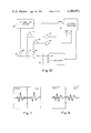
FIG. 6 is a block diagram for a simplified NDT system using a transmitter and a receiver;
FIG. 7 is the graphical representation of electrical pulses for a test material of a short acoustic path length;
FIG. 8 is a graphical representation of electrical pulses generated by the receiver for a relatively much longer path length;
FIG. 9 is a schematic representation of a system using a 3-transducer method;
FIG. 10 is a simplified schematic representation of a velocity scan system using 3-transducers;
FIG. 11 is a schematic representation of a system using 4-transducer method;
FIG. 12 is a block diagram of 4-transducer method including electronic circuitry; and
FIG. 13 is a graphical representation of variation of the velocity of torsional waves with a certain characteristic of the test wire.
DESCRIPTION OF A PREFERRED EMBODIMENT
Referring to the drawings wherein like reference characters designate identical or corresponding parts throughout the several figures, and more particularly, to FIG. 1 thereof, a perspective view of the NDT system 10 according to the teachings of the subject invention is shown. The system 10 includes a magnet 12 with pole pieces 14 and 16 and having a magnetization axis shown by arrow 18. It further includes coil forms 20 and 22 for a transmitter- transducer having coils 24 and 26 respectively wound thereon. Coils 24 and 26 and pole pieces 14 and 16 form a gap 28 which is the gap through which test wire 30 is pulled as shown by arrow 31. FIG. 2 indicates an end view of test wire 30 placed in the gap provided by the transducer. The transducer as shown in FIG. 2 includes a magnet with pole pieces 14 and 16. FIG. 2 shows coil forms 20 and 22 and four transducer coil legs 34, 36, 38 and 40 which are wound by a nylon spacer 42. Coil legs 44, 46, 48 and 50 are likewise wound on coil form 20 on the opposite side of nylon spacer 42. In a similar fashion coil legs 52, 54, 56 and 58 are wound on coil form 22 on one side of nylon spacer 60 and coil legs 62, 64, 66 and 68 are wound on coil form 22 on the opposite side of nylon spacer 60. As can be seen from FIG. 2, the test wire 30 is placed in gap of the transducer. When electrical pulses of high current amplitude (500 A) and short duration (i.e., a few μsec where 1 μsec=10-6 sec) are passed through coil legs 34-40; 44-50; 52-58 and 62-68, eddy currents are generated on the surface of test wire 30 which, via the magnetic induction between pole pieces 14 and 16, apply torque on the test wire 30 and thus create torsional waves on the test wire 30 which propagate in the test wire along is longitudinal axis. (It should be noted that a different geometrical orientation for the transducer can also be used.) As shown in FIG. 3, a torsional wave starts in test wire 30 at point 72 which is close to the position of the transmitter-transducer coil 74. The torsional waves generated at point 72 in test wire 30 propagate in both directions as shown by arrows 76 and 78. Torsional wave represented by arrow 76 propagates in the direction of receiver-transducer coil 79 located at position 77 of the test wire 30.
FIG. 4 schematically shows test wire 30 as acoustic medium of length L and transmitter-tranducer 82 and receiver-transducer 84 placed along the axis of test wire 30. FIG. 5 shows a corresponding train of pulses displayed on an oscilloscope. As shown in FIGS. 3 and 5, electrical pulses are generated in groups of 4 when end reflections are included and the velocity c' of the torsional wave can be obtained by dividing twice the length, L, of the test wire by the time period between the two positions of the same wave. This gives 2L/τ where L and τ are shown in FIGS. 4 and 5. The system attenuation α' is depicted in FIG. 5. FIG. 7 shows the pulse amplitude as a function of time for a test wire of, in effect, short length (L) whereas FIG. 8 shows the amplitude variation of a torsional wave with time for a relatively long test wire of length L' (L'>>L). It is to be noted that the vertical scale used in FIG. 7 is 10 times larger than the corresponding scale in FIG. 8, yet the pulses are still resolved in time and have about the same shape. This is an example of evidence we have developed that the only acoustic wave mode involved is the lowest-order torsional wave mode, whose velocity of propagation is free of dispersion.
In Table 1 are shown velocity and attenuation data (c' and α') measured on short lengths of various wire materials by means of a 2-transducer setup, in comparison with plate and bulk values.
              TABLE 1                                                     
______________________________________                                    
PULSED ULTRASOUND DATA                                                    
            WIRE       VELO-     ATTENUA-                                 
            DIAMETER   CITY.sup.(a)                                       
                                 TION.sup.(a)                             
MATERIAL    (mm)       (10.sup.3 m/s)                                     
                                 (Nepers/m)                               
______________________________________                                    
AL ALLOY WIRE                                                             
            1.1        3.0       0.034                                    
"GOOD" MMC.sup.(b)                                                        
WIRE        1.2        2.6       0.76                                     
"BAD" MMC.sup.(c)                                                         
WIRE        1.4        2.1       2.6                                      
MMC.sup.(b) PLATE                                                         
            N/A          2.8.sup.(c)                                      
                                 --                                       
AL ALLOY    N/A          3.0.sup.(d)                                      
                                 0.55.sup.(d)                             
(BULK)                                                                    
______________________________________                                    
 NOTES:                                                                   
 .sup.(a) 1st order, 140 kHz torsional wave except as noted.              
 .sup.(b) Graphite/Al Metal Matrix Composite.                             
 .sup.(c) Datum of Blessing, Elban, & Foltz (1978); at 10 MHz.            
 .sup.(d) From Viktorov (1978); at 1 MHz.                                 
FIG. 6 depicts a setup exemplifying the 2-transducer arrangement of FIGS. 3 and 4, except that the test wire is too long for end reflections to be of concern, and is moving as opposed to being stationary. The schematic representation is of a system 80 using a transmitter-transducer and a receiver-transducer. Output from a pulser is fed to coil 74 of transducer 82 which generates torsional waves in test wire 30. They move along the longitudinal axis of the wire 30 and reach coil 70 of receiver-transducer 84 which converts them into electrical signals which are impedance matched by transformer 88 and are amplified by amplifiers 90 and 92 and are passed through a bandpass filter (BPF) 94 thereafter. After passing the signals through gated peak detector (GPD) 96 and integrator 98, they are plotted on X--Y plotter 100. Output of bandpass filter 94 is also displayed on an oscilloscope 102. A signal into gated peak detector 96 is used for synchronization with the pulser providing current pulses to transmitter-transducer 82. The test wire, via a coupler 101, is attached to the carriage arm of the X--Y plotter. (Thus the increments in wire position occurring during scanning are equal to the increments in the X-coordinate on the X--Y plot.) FIG. 9 is a diagrammatic representation of a 3-transducer system according to the teachings of the subject invention. As shown in FIG. 9, three transducers 103, 104 and 106 are placed in close proximity of the test wire 30 in a line that is parallel to test wire 30 of length L. Transducer 103 acts as a transmitter whereas transducer 104 is used as a first receiver and transducer 106 is used as a second receiver. All these transducers, as in the preceding setup, are EMT's and are typically bi-directional and acoustically transparent. The distance between 104 and 106 can be made large enough so that the pulses need not overlap in that distance. FIG. 10 shows a simplified schematic representation of a simple version of the velocity scan system wherein a pulse from pulser 110 is used to energize transmitter 103. Pulses 112 and 114 are generated by receivers 104 and 106 respectively and after their respective amplification by amplifiers 116 and 118, respectively, are fed to the inputs Y1 and Y2 of a dual-channel amplifier. By use of suitable time-base units for manual overlapping of the two received pulses, the time-delay data for a torsional wave from wire 30 can be plotted on the Y-axis of XY-recorder 122. A synchronization pulse from pulser 110 such as Velonex 350 is used to trigger oscilloscope 120 such as Tektronix 7704.
A 4-transducer setup is shown diagrammatically in FIG. 11. This setup measures accurately attenuation and/or velocity in a test wire 30 of very long length. In this system, transducer 130 acts as a first transmitter and transducer 132 acts as a second transmitter. Transducers 134 and 136 act as the two receivers. The transducers 130, 132, 134 and 136 are placed close to test wire 30 along a line parallel to the axis of the test wire. FIG. 12 shows a block diagram of a system using four transducers. As shown in FIG. 12, test wire 30 is moved in the direction of arrow 140 and is guided by two pairs of rollers 142 and 144. These rollers can be replaced by nylon sleeves or the like. Two transmitter- transducers 130 and 132 sandwich two receiver- transducers 134 and 136; all transducers are placed in line along of the test wire 30. The signals received from transducers 134 and 136 are impedance matched by transformer 150 and are amplified by preamplifier 152 and amplifier 154. The output of amplifier 154 is passed through bandpass filter 156 and then displayed on a CRT 160 and is fed into an AC log circuit 162, the output of which is fed to Gated Peak Detectors (GPD) circuits 164, 166, 168 and 170. Pulser 172 energizes transducers 130 and 132 through an impedance matching transformer 174 and receives a synchronizing signal from synchronizer generator 178 which also provides a synchronizing signal to GPD circuits 164-170. The output of circuits 164 and 166 is combined in difference amplifier 180 and the output of circuits 168 and 170 is combined in circuit 182. Outputs of circuits 180 and 182 are combined in a summing amplifier 184 which has an output which is proportional to the attenuation of the torsional wave ##EQU1## in the wire part bounded by receiver- transducers 134 and 136. It should be noted the voltages are of the form Vij where "j" refers to the transmitter involved and "i" to the receiver.
The value of the velocity of the torsional wave is obtained by measuring a difference in two time delay differences as opposed to a single delay difference (Δt) used in the case of 3-transducer system as described above. Such a difference of the differences would involve four time measurements tij (at which the peak amplitudes of the pulse voltages Vij occur), just as the attenuation measurement involves four corresponding voltage amplitude measurements. As will be later shown, the velocity c for a finite length test wire will be given by
cα(t.sub.12 -t.sub.22 -t.sub.11 +t.sub.21).sup.-1.
As for the α expression, the expression for c is independent of the gap while also applying to the test wire part bounded by receiver- transducers 134 and 136. (It should be noted that the time delays are of the form tij where "j" refers to the transmitter and "i" refers to the receiver involved.)
We define voltage as the "level" of a given receiver signal after the signal has been appropriately amplified and/or otherwise conditioned. We use the symbol V for voltage. The voltage due to an ultrasound pulse being fired from transmitter "j" and being received by receiver "i" is Vij. We assume that the transducer-test wire system is linear, so that, for example, a doubling of input current to a transmitter-transducer results in a doubling of the received voltage. (This is the case for Lorentz forces invoked here as the transduction mechanism.) Then, in the frequency domain (as when data are displayed on the CRT of a spectrum analyser) and roughly in the time domain (as when data are displayed on the CRT of an oscilloscope), this voltage can be regarded as the product of two factors: V=EF. Here E gives the contribution from the electronics and from the transducers; F gives the contribution from just the material test medium, as resulting for example from the general tendency of material attenuation to increase with increase in ultrasound frequency. Let E have 3 parts: E=RST, where R, S and T refer respectively to the receiver-transducer, electronics (viz., amplifiers), and transmitter-transducer. For clarity, let F=exp [-(αΔX)], where α is the average attenuation over the test wire distance ΔX between the transmitter-receiver EMT pair involved.
Refer again to FIG. 11. It can be easily verified that, for transmitter T1 (130) and receivers R1 (134) and R2 (136), ##EQU2## The result is independent of transmitter factor T1 and thus independent of the transmitter-test wire gap. With Sij =Pi Qj taken as a product of 2 factors, one for the transmitter electronics (Qj) and one for the receiver electronics (Pi), this expression becomes, ##EQU3## It can also be shown that this reduces to, ##EQU4## where ΔX is the distance between receivers 134 and 136. (The key to deriving this result is in understanding the difference between the average and local values (α and α respectively) of attenuation.)
A similar process of reasoning indicates that for transmitter T2 (132) and receivers R1 (134) and R2 (136), ##EQU5## Thus, Eqs. (b) and (c) lead to, ##EQU6## and thus to, ##EQU7## This result does not depend on Pi or Qj and so is independent of transducer gaps. Also, by definition, ##EQU8## Thus, one way (but not the only way) to experimentally measure the local value of attenuation involves the choice of small ΔX.
Using an approach similar in spirit to the one used in the preceding calculations, one can also find a gap-independent value of average velocity c as,
c=2ΔX/[(t.sub.21 -t.sub.11)+(t.sub.12 -t.sub.22)].
Also, by definition, ##EQU9## In practice, the agreement between the measurement of c by means of 3-transducer and 4-transducer setups is much closer than the corresponding agreement for α measurements by 3-transducer and 4-transducer setups.
It should be noted that the use of a multiple transducer technique would not be practical without the essentially acoustically transparent nature of the EMT's used. This acoustic transparency is due mostly to the lack of physical contact between the transducers and the test wire and to a lesser extent to the relatively low acoustic efficiency of EMT's. Contacting transducers such as piezoelectric would not be suitable for use in multiple transducer setups. It should further be noted that the gap independence has been tested and confirmed in various experiments with 2-transducer, 3-transducer and 4-transducer setups.
FIG. 13 indicates the velocity of the torsional wave as a function of percentage of volume of graphite fiber content in a test wire of graphite/aluminum metal matrix composite material using a 3-transducer setup of FIG. 10.
Thus, using the apparatus and the technique described above to measure the velocity and attenuation of a torsional wave generated in moving and/or stationary test wire using EMT's involves measurement of the distance between the transducers and also measuring the amplitude of the electrical pulses received as a result of torsional wave produced in the test wire when electrical pulses of high amplitude currents are passed through the transmitter-transducer coils.
Obviously, many modifications and variations of the present invention are possible in the light of the above teachings. For example, it is possible to use test materials of different configuration (e.g., plates) and of different smoothness and other characteristics. Furthermore, the system and the technique can be used as well for ferromagnetic materials with some modification of the system. Additionally, torsional waves of different mode order and waves of other modes (such as longitudinal) can be produced. Another variation permits the geometrical configuration of the magnet and coil portions of the transducers used as receivers and transmitters can also be varied. Additionally, the wire testing system can also be used for stationary test materials and/or moving test materials. Furthermore, the electronic components forming the wire testing system can be arranged in ways other than the one described above without deviating from the teachings of the subject invention.
It is therefore understood that within the scope of the appended claims the invention may be practiced otherwise than as specifically described.

Claims (12)

What is claimed is:
1. An apparatus for nondestructive testing (NDT) an electrically conductive and elongated test material having a longitudinal axis using noncontacting electromagnetic ultrasound transducers (EMT'S) which comprises:
a magnet with pole pieces forming a gap and with the direction of magnetization thereof being generally perpendicular to the longitudinal axis of the test material;
at least one noncontacting electromagnetic ultrasound transducer (EMT) as a transmitter-transducer having the coil thereof adjustably positioned along the longitudinal axis of the test material to have electrical pulses passing therethrough in a direction parallel to the longitudinal axis of the test material and thus generating torsional ultrasound waves in the test material traveling along the longitudinal axis thereof; and
at least one more noncontacting electromagnetic ultrasound transducer (EMT) as a receiver-transducer having the coil thereof adjustably positioned colinear with said transmitter-transducer and receiving the torsional ultrasound waves traveling along the longitudinal axis of the test material.
2. The apparatus of claim 1 wherein said transmitter-transducer and receiver-transducer are aligned along the longitudinal axis of said test material.
3. The apparatus of claim 2 which further includes an additional electromagnetic-ultrasound transducer (EMT) to be used as a second transducer-receiver, thus using said apparatus as a 3-transducer setup for studying the properties of said test material.
4. The apparatus of claim 3 which includes one more additional electromagnetic ultrasound transducer (EMT) to be used as a second transducer-transmitter, thus using said apparatus as a 4-transducer setup for studying the properties of said test material.
5. The apparatus of claim 4 wherein said test material is a wire having an uneven outer surface.
6. The apparatus of claim 5 wherein said test material is a composite wire having non-metallic fibers dispersed in a metal matrix.
7. The apparatus of claim 4 wherein each of said first and second transmitter-transducers and said first and second receiver-transducers includes a magnet, a pair of coil forms and a coil wound on said pair of coil forms.
8. The apparatus of claim 4 wherein each of said electromagnetic-ultrasound transducers (EMT's) is bidirectional.
9. The apparatus of claim 4 wherein each of said electromagnetic-ultrasound transducers (EMT'S) is acoustically transparent.
10. A nondestructive testing (NDT) method for studying the properties of a test wire using a plurality of electromagnetic ultrasound transducers (EMT'S) and one or more magnets which includes the steps of:
arranging the longitudinal axis of said wire generally perpendicular to the direction of magnetic field of said magnet;
placing a first member of said plurality of EMT'S adjacent to said test wire along the longitudinal axis thereof to act as a transmitter;
placing a second member of said plurality of EMT'S adjacent to said test wire and colinear with said first member of said plurality of EMT'S to act as a receiver;
generating a torsional waves in said wire traveling along the axis thereof by electrically exciting said first member of said plurality of EMT'S measuring the velocity and attenuation of said torsional waves by receiving said torsional waves by said second member of said plurality of EMT'S.
11. The method of claim 10 which further includes the step of placing a third member of said plurality of EMT'S colinear with said first and second members of said plurality of EMT'S to act as a second receiver for said torsional waves.
12. The method of claim 11 which further includes the step of placing a fourth member of said plurality of EMT'S to act as a second transmitter for said torsional waves.
US06/256,750 1981-04-23 1981-04-23 Apparatus and method for quantitative nondestructive wire testing Expired - Fee Related US4380931A (en)

Priority Applications (1)

Application Number Priority Date Filing Date Title
US06/256,750 US4380931A (en) 1981-04-23 1981-04-23 Apparatus and method for quantitative nondestructive wire testing

Applications Claiming Priority (1)

Application Number Priority Date Filing Date Title
US06/256,750 US4380931A (en) 1981-04-23 1981-04-23 Apparatus and method for quantitative nondestructive wire testing

Publications (1)

Publication Number Publication Date
US4380931A true US4380931A (en) 1983-04-26

Family

ID=22973449

Family Applications (1)

Application Number Title Priority Date Filing Date
US06/256,750 Expired - Fee Related US4380931A (en) 1981-04-23 1981-04-23 Apparatus and method for quantitative nondestructive wire testing

Country Status (1)

Country Link
US (1) US4380931A (en)

Cited By (14)

* Cited by examiner, † Cited by third party
Publication number Priority date Publication date Assignee Title
DE3601373A1 (en) * 1985-01-22 1986-08-28 Siderca S.A. Industrial y Comercial, Capital Federal DEVICE FOR THICKNESS MEASUREMENT USING ULTRASONIC
EP0440317A1 (en) * 1990-01-31 1991-08-07 MANNESMANN Aktiengesellschaft Method and apparatus for testing ferromagnetic work pieces by ultrasonic waves
US5456113A (en) * 1992-11-06 1995-10-10 Southwest Research Institute Nondestructive evaluation of ferromagnetic cables and ropes using magnetostrictively induced acoustic/ultrasonic waves and magnetostrictively detected acoustic emissions
US5581037A (en) * 1992-11-06 1996-12-03 Southwest Research Institute Nondestructive evaluation of pipes and tubes using magnetostrictive sensors
EP0829309A2 (en) * 1996-09-13 1998-03-18 Siemens Aktiengesellschaft Ultrasound generating method for non-destructive testing and test apparatus
DE19922058A1 (en) * 1999-05-14 2000-11-23 Fraunhofer Ges Forschung Examination and testing of e.g. lengthy rock anchors and bridge sections, employs transducers to excite them with specific ultrasound modes, digitizing reflected wave to locate and characterize e.g. fissures or corrosion damage
WO2001071953A1 (en) * 2000-03-23 2001-09-27 Onera (Office National D'etudes Et De Recherches Aerospatiales) Installation with piezoelectric element for equipping a structure and piezoelectric element for same
US6810743B2 (en) 2001-08-01 2004-11-02 The United States Of America As Represented By The Administrator Of The National Aeronautics And Space Adminstration Non-destructive evaluation of wire insulation and coatings
US7107203B1 (en) * 2000-09-06 2006-09-12 Quickturn Design Systems Inc. High speed software driven emulator comprised of a plurality of emulation processors with improved board-to-board interconnection cable length identification system
US20100101076A1 (en) * 2007-05-21 2010-04-29 Jeff Parrell Device and method for internal flaw magnification or removal
US20140251705A1 (en) * 2011-12-27 2014-09-11 Karl Salzmann Vehicle
CN104849345A (en) * 2015-04-24 2015-08-19 中国矿业大学 Pulsed eddy current detection device for mine vibrating screen beam fatigue cracks
CN106513290A (en) * 2016-12-28 2017-03-22 南京航空航天大学 Transducer and method for improving electromagnetic acoustic signal strength
RU184335U1 (en) * 2018-07-04 2018-10-22 Федеральное государственное автономное образовательное учреждение высшего образования "Национальный исследовательский Томский политехнический университет" PROBE FOR INSPECTION OF EXTENDED CONSTRUCTION STRUCTURES

Citations (5)

* Cited by examiner, † Cited by third party
Publication number Priority date Publication date Assignee Title
US3850028A (en) * 1972-11-16 1974-11-26 Rockwell International Corp Method for ultrasonic inspection
US4092868A (en) * 1976-10-12 1978-06-06 Rockwell International Corporation Ultrasonic inspection of pipelines
US4164873A (en) * 1976-09-28 1979-08-21 Hoesch Werke Aktiengesellschaft Method of and device for material checking by ultra sound while employing an electrodynamic sound converter
US4307616A (en) * 1979-12-26 1981-12-29 Rockwell International Corporation Signal processing technique for ultrasonic inspection
US4312231A (en) * 1979-07-06 1982-01-26 Nippon Steel Corporation Apparatus for generating and detecting an electromagnetic ultrasonic wave

Patent Citations (5)

* Cited by examiner, † Cited by third party
Publication number Priority date Publication date Assignee Title
US3850028A (en) * 1972-11-16 1974-11-26 Rockwell International Corp Method for ultrasonic inspection
US4164873A (en) * 1976-09-28 1979-08-21 Hoesch Werke Aktiengesellschaft Method of and device for material checking by ultra sound while employing an electrodynamic sound converter
US4092868A (en) * 1976-10-12 1978-06-06 Rockwell International Corporation Ultrasonic inspection of pipelines
US4312231A (en) * 1979-07-06 1982-01-26 Nippon Steel Corporation Apparatus for generating and detecting an electromagnetic ultrasonic wave
US4307616A (en) * 1979-12-26 1981-12-29 Rockwell International Corporation Signal processing technique for ultrasonic inspection

Non-Patent Citations (2)

* Cited by examiner, † Cited by third party
Title
Frost et al., "Velocity and Attenuation in Metal Waveguides," paper given session Physical Acoustics IV; Ultrasonics and Materials, Acoustical Society of America Spring Meeting, Apr. 24, 1980.
Frost et al., "Velocity and Attenuation in Metal Waveguides," paper given session Physical Acoustics IV; Ultrasonics and Materials, Acoustical Society of America Spring Meeting, Apr. 24, 1980. *

Cited By (21)

* Cited by examiner, † Cited by third party
Publication number Priority date Publication date Assignee Title
DE3601373A1 (en) * 1985-01-22 1986-08-28 Siderca S.A. Industrial y Comercial, Capital Federal DEVICE FOR THICKNESS MEASUREMENT USING ULTRASONIC
EP0440317A1 (en) * 1990-01-31 1991-08-07 MANNESMANN Aktiengesellschaft Method and apparatus for testing ferromagnetic work pieces by ultrasonic waves
US5456113A (en) * 1992-11-06 1995-10-10 Southwest Research Institute Nondestructive evaluation of ferromagnetic cables and ropes using magnetostrictively induced acoustic/ultrasonic waves and magnetostrictively detected acoustic emissions
US5581037A (en) * 1992-11-06 1996-12-03 Southwest Research Institute Nondestructive evaluation of pipes and tubes using magnetostrictive sensors
EP0829309A2 (en) * 1996-09-13 1998-03-18 Siemens Aktiengesellschaft Ultrasound generating method for non-destructive testing and test apparatus
EP0829309A3 (en) * 1996-09-13 2000-11-22 Siemens Aktiengesellschaft Ultrasound generating method for non-destructive testing and test apparatus
DE19922058A1 (en) * 1999-05-14 2000-11-23 Fraunhofer Ges Forschung Examination and testing of e.g. lengthy rock anchors and bridge sections, employs transducers to excite them with specific ultrasound modes, digitizing reflected wave to locate and characterize e.g. fissures or corrosion damage
WO2001071953A1 (en) * 2000-03-23 2001-09-27 Onera (Office National D'etudes Et De Recherches Aerospatiales) Installation with piezoelectric element for equipping a structure and piezoelectric element for same
FR2806823A1 (en) * 2000-03-23 2001-09-28 Onera (Off Nat Aerospatiale) INSTALLATION WITH PIEZOELECTRIC ELEMENT FOR THE EQUIPMENT OF A STRUCTURE; PIEZOELECTRIC ELEMENT FOR SUCH AN INSTALLATION
US20040046483A1 (en) * 2000-03-23 2004-03-11 Marc Dupont Installation with piezoelectric element for equipping a structure and piezoelectric element for same
US6960867B2 (en) 2000-03-23 2005-11-01 Onera (Office National D'etudes Et De Recherches Aerospatiales) Installation with piezoelectric element for equipping a structure and piezoelectric element for same
US7107203B1 (en) * 2000-09-06 2006-09-12 Quickturn Design Systems Inc. High speed software driven emulator comprised of a plurality of emulation processors with improved board-to-board interconnection cable length identification system
US6810743B2 (en) 2001-08-01 2004-11-02 The United States Of America As Represented By The Administrator Of The National Aeronautics And Space Adminstration Non-destructive evaluation of wire insulation and coatings
US20100101076A1 (en) * 2007-05-21 2010-04-29 Jeff Parrell Device and method for internal flaw magnification or removal
US8943681B2 (en) * 2007-05-21 2015-02-03 Oxford Superconducting Technology Device for internal flaw magnification during wire drawing
US20140251705A1 (en) * 2011-12-27 2014-09-11 Karl Salzmann Vehicle
US10093142B2 (en) * 2011-12-27 2018-10-09 iOLS GmbH Vehicle
CN104849345A (en) * 2015-04-24 2015-08-19 中国矿业大学 Pulsed eddy current detection device for mine vibrating screen beam fatigue cracks
CN104849345B (en) * 2015-04-24 2017-12-19 中国矿业大学 A kind of Pulsed eddy current testing device of vibration screen for mineral crossbeam fatigue crack
CN106513290A (en) * 2016-12-28 2017-03-22 南京航空航天大学 Transducer and method for improving electromagnetic acoustic signal strength
RU184335U1 (en) * 2018-07-04 2018-10-22 Федеральное государственное автономное образовательное учреждение высшего образования "Национальный исследовательский Томский политехнический университет" PROBE FOR INSPECTION OF EXTENDED CONSTRUCTION STRUCTURES

Similar Documents

Publication Publication Date Title
US6424150B2 (en) Magnetostrictive sensor rail inspection system
US4380931A (en) Apparatus and method for quantitative nondestructive wire testing
US6920792B2 (en) Transducer guided wave electromagnetic acoustic
Edwards et al. Characterisation of defects in the railhead using ultrasonic surface waves
US4979125A (en) Non-destructive evaluation of ropes by using transverse impulse vibrational wave method
US4307616A (en) Signal processing technique for ultrasonic inspection
Khalili et al. Relative ability of wedge-coupled piezoelectric and meander coil EMAT probes to generate single-mode Lamb waves
US4305294A (en) Ultrasonic apparatus and method for measuring wall thickness
EP2567224B1 (en) Method and device for non-destructive material testing by means of ultrasound
Tu et al. An external through type RA-EMAT for steel pipe inspection
US3436958A (en) Ultrasonic pipe testing method and apparatus
US2656714A (en) Method and apparatus for nondestructive investigation of magnetostrictive solids
CN113533504A (en) Sub-surface crack quantitative measurement method based on laser ultrasonic surface wave frequency domain parameters
CN105424798A (en) Method for actively detecting defects in metal thin-walled structure part
US4586381A (en) Nondestructive ultrasonic transducer
WO2004106913A1 (en) Guided wave electromagnetic acoustic transducer
JPS5831872B2 (en) Non-contact ultrasonic flaw detection method
EP0429446A1 (en) Non-destructive evaluation of ropes by using transverse vibrational wave method
Murav’ev et al. Acoustic assessment of the internal stress and mechanical properties of differentially hardened rail
JP3199941B2 (en) Continuous magnetostriction measuring method and apparatus
Sun Application of guided acoustic waves to delamination detection
Suchkov The main advantage of electromagnetic-acoustic testing technique
JP2001013118A (en) Electromagnetic ultrasonic probe
KR102203609B1 (en) Electromagnetic acoustic transducer and pipe inspection apparatus comprising the same
Heo et al. Detection of an axial surface microcrack in steel wire rods with noncontact ultrasonic reverberation spectroscopy

Legal Events

Date Code Title Description
AS Assignment

Owner name: UNITED STATES OF AMERICA, AS REPRESENTED BY THE SE

Free format text: ASSIGNMENT OF ASSIGNORS INTEREST. SUBJECT TO LICENSE RECITED,THIS INSTRUMENT ALSO SIGNED BY THE PENNSYLVANIA STATE UNIVERSITY;ASSIGNORS:FROST, HAROLD M.;PROUT, JAMES H.;REED, ROBERT W.;REEL/FRAME:003899/0073;SIGNING DATES FROM 19810601 TO 19810622

FEPP Fee payment procedure

Free format text: MAINTENANCE FEE REMINDER MAILED (ORIGINAL EVENT CODE: REM.); ENTITY STATUS OF PATENT OWNER: LARGE ENTITY

LAPS Lapse for failure to pay maintenance fees
STCH Information on status: patent discontinuation

Free format text: PATENT EXPIRED DUE TO NONPAYMENT OF MAINTENANCE FEES UNDER 37 CFR 1.362

FP Lapsed due to failure to pay maintenance fee

Effective date: 19870426