US2184159A - Apparatus for measuring area - Google Patents
Apparatus for measuring area Download PDFInfo
- Publication number
- US2184159A US2184159A US90260A US9026036A US2184159A US 2184159 A US2184159 A US 2184159A US 90260 A US90260 A US 90260A US 9026036 A US9026036 A US 9026036A US 2184159 A US2184159 A US 2184159A
- Authority
- US
- United States
- Prior art keywords
- belt
- shaft
- scanning
- work
- area
- Prior art date
- Legal status (The legal status is an assumption and is not a legal conclusion. Google has not performed a legal analysis and makes no representation as to the accuracy of the status listed.)
- Expired - Lifetime
Links
Images


Classifications
-
- G—PHYSICS
- G01—MEASURING; TESTING
- G01B—MEASURING LENGTH, THICKNESS OR SIMILAR LINEAR DIMENSIONS; MEASURING ANGLES; MEASURING AREAS; MEASURING IRREGULARITIES OF SURFACES OR CONTOURS
- G01B11/00—Measuring arrangements characterised by the use of optical techniques
- G01B11/28—Measuring arrangements characterised by the use of optical techniques for measuring areas
-
- C—CHEMISTRY; METALLURGY
- C14—SKINS; HIDES; PELTS; LEATHER
- C14B—MECHANICAL TREATMENT OR PROCESSING OF SKINS, HIDES OR LEATHER IN GENERAL; PELT-SHEARING MACHINES; INTESTINE-SPLITTING MACHINES
- C14B1/00—Manufacture of leather; Machines or devices therefor
- C14B1/28—Machines for treating leather combined with devices for measuring and printing
Definitions
- i i w1 invention relates tothe measurement of 'w, and with regard to certain more specinc features, to apparatus for measuring area by the oi light-sensitive devices.
- the invention mayloe no the provision oi apparatus for measuring area wherein a beam oi light, or a plurality o! beams oi' light, are moved across a surface to be measured which is superposed on a surface of a l@ derent optical character, so that a photosensitive device will be actuated in' accordance with the interference or non-interference oi the light beam by the said surface.
- Fig. 5 is a horizontal section taken substantially along line B-l of Fig. 3:
- Fig. 6 is a atic representation o! the optical system embodied in the apparatus of the preceding iigures; L
- Fig. 7 is a diagrammatic representation o! the electrical system embodied in the apparatus of the preceding figures;
- Fig. 8 isan axial cross section of a magnetic clutch
- Pig. 9 is an axial cross section of a one-.turn clutch mechanism Figures 10 and 11 are sections taken substantially along lines IU-III and il-ll of Fig. 9:
- Fig. 15 is ar enlar optical system
- ged diagrammatic view of an liiig. ⁇ 16 is a top plan view of a counter: i Y I y Fig. 17 is an end elevation of the counter oi Pig. 16; llig.4 18 is a. side elevation oi the "counter .oi 28 Fig. 16. certain parts being broken away; f Fig. 19 is a cross section taken substantially on line ⁇ -I! of Figures 16 and 17;
- Fig. 21 is' a diagrammatic view similar to Fig. B. illustrating another embodiment oi' the invention
- Fig. 22 is a front elevation of a reiiector usedin eal section oi' the counter of continuous one
- the provision oi apparatus ot the class described which is simple to operate and which yields results of an inherent high accuracy-.
- Other objects will be in part obvious and in Dart pointed out hereinafter.
- the invention accordingly comprises the elements and combinations oi' elements, and features y oi construction and operation,.which will be exempiided in the apparatus hereinafter described, and the scope oi the application oi which'will be indicated in the following claims.
- Fig'. 2 is an enlarged fragment oi Fig. l;
- Fig. 3 is an end elevation 'oi the apparatus shown in Fig. 2;
- Fig. i is a horizontal section taken substantially along line i-t oi Fig. d;
- Fig. 33 is a vertical section taken substantially 3g 'along line 23-23 oi Fig. 22;
- Hg. 24 is a horizontaieotion taken substan tially along line 24-24 o! Fig. 22;
- Fig. 25 is a diagrammatic viewV similar to Fig. 6,
- inven- FigeZil is a fragmentary elevation ot abank of photosensitive tubes used in the Eig. 25 embodiment;
- Fig. 28 is a diagrammatic view similar to Iilg. 8,
- Il'ig.' ⁇ 29 is a diagrammatic iront elevation of a -1 reiiector assembly used in the Fig. 28 embodiment;
- Fig. 30 is a section taken substantially along line 3l-3l of F18. 28,' illustrating a light chopper disc: n
- Fig. 3i is a front elevation of another embodiment of the invention.
- Fig. 32 is a vertical section along line 82--32 of Fig. 31;
- Fig. 33 is a vertical section taken along line 33-33 of Fig. 32; l
- Fig. 34 is an enlarged fragmentary front elevation of a scanner embodiment
- Fig. 35 is an enlarged vertical section taken substantially along Fig. 36 is a side line 35-35 of Fig. l34;
- Fig. 37 is a top plan view of the embodiment of Fig. 36; g
- Fig. 39 isanother matic fragment-,aryv
- Fig. 40 is an enlarged of a scanner: belt used in the Fig. 36.
- One method heretofore proposed for ⁇ the measurement oiv the area of work piecesv by photoelectric methods'comprises scanning the work piece with successive beams of light that are rerlected to a photosensitive device so that the dei vice responds differently tovreiiected light from the work piece as contrasted to reflected light from its background, and then integrating the responses with the rate of travel ofthe scanning beam across the ⁇ work to obtain an expression of area of the workpiece.
- a dimculty with this has been that it is limited by the character of the scanning apparatus available.
- the integrating mechanism has been coupled to the rotating discfor rotation therewith, on the supposition that the .angular displacement of the scanning disc was a true linear function of the rate of travel of the spot of light caused by the interception of the scanning beam by the work piece.
- a further principal object of the invention is to provide the measuring system with automatic means for presenting, measuringand withdrawing'a rapid succession of work pieces.
- the beam may be made equal to the width of a row of these spaces and may sweep across the entire row, but it will perform essentially it is considerably vsmaller than the width of such a row and sweeps across the center line oi the row. In either event the beam will scan successive spaoes in the row, and by usinga suitable detector with it, it can be made to tellwhich spaces are covered by the work.
- the word the same function if4 4or increment be as narrow as conveniently pos sible, because the narrower the path, the smaller will be lthe error introduced bythe terminal ehect of the work piece.
- terminal effect is meant that small edge fragment of the work piece that overlaps the scanned path a small distance insumeient to record on the photosensiuve devise, the area of which is therefore not counted', or l which overlaps the scanned path sulcientiy to be counted, but insumciently actually to repre; sent the area indicated by the count.
- the apparatus'. of the first embodiment of the present invention may be considered as made up of a work feeding mechanism, a scanning system (comprising a beam projector and a beam reflector or interceptor), a scanning system feeding mechanism, a detection system. and an integrating system givina expressions of area as an end ⁇ result.
- the work ieedimi,r mechanism of the present invention is sho in Figures i. 2, and 3. Rec- .:i 1v f .iler frames l, oi ⁇ wood or metal or other suitable material, are provided for each of the hides i to 4be measured.
- the hides 3 are attached to the frames l by strings t, a. mul/fplicity of which are provided around the interior edge oi the frame to take .care of dilerent sizes und shapes of hides.
- the strings d stretch the hide t so that its maximum surface area. is pre- 1 sented to the front of the frame.
- the hide is stretched so that its plane is in the plane of the frame.
- the frames i are commonly provided in tanneries for stretching the hides 3 during their tanning,- and hence the positioning of the hides i on the frames i ordinarily requires no additional work,
- Numeral il indicates an endless chain belt which is supported by sprocket wheels i3 and i5 at its ends. Intermediate idler sprocket wheels (not shown) may be provided for preventing the upper lap oi the chain ll from sagging, or. the upper lap may travel in a channel or, for exampie, on top of the slide l-as shown. At'suitably smced intervals, the chain 4vvitl'i does il which extend belt il isprovlded over the slide l im edgeof a hide frame l. dogs il will be indicatedV Position to abut the hereinafter.
- the tracks tu are in other directions.
- the optical or lens system 5I may best be delenses 65 and di is orhid'e 3. It will xthat also passes over a sprocket wheel 23 on a main drive shaft 25. Suitable motivating force is provided for the main'drive shaft 2t, so that the belt H is driven from the sprocket wheel I3. The direction of rotation is such that thenpper lap of the belt il moves from the right to the left Il of the belt Il thus propel along the slides 1 and 8 whatever frames i they Scanning system f
- the scanning systemof the present invention is shown in Figures 1, 2. 3; 4, 5, 6, 7, 14, and 15. Its supporting mechanism will first be described.
- Numeral 2l ⁇ ( Figures 2 and 3) indicates a car- I 'iage that comprises a hollow rectangular frameand back pieces 29 and 3
- the carriage 2l is moved by the scanning system feeding mechanism hereinafter to be described.
- the posts 4l are deslrably braced to the cross pieces i3 by struts di.
- a horizontal shell W is supportedon the posts di somewhat below the upper ends thereof, and a parallel shelf' t? is provided at the upper ends of the posts di.
- the shelves ib and di support the beam projector mechanism, which generally comprise a light source 49, an optical or lens system indicated generally by numeral 5l, and a scanning device forming aparticular feature oi' the present invention.
- the light source 49 may comprise an incandescentllament bulboi' theconcentrated illament type. as usually used for projection equipment, or any other vsource of sufllcient area and intensity. It is so mounted (on a block 53) that its illament is positioned midway, vertically, between the upper and lower inner edges of the work-supporting frame l. It is preferably shielded. or provided with a yreflector system such as used in small motion picture projectors. As little stray light as possible is-allowed to escape supports the beam pro back piece il supports the scribed by reference ⁇ to Figures 6 and 15. It comprises a lens 55, which throws an image oi the source @il on a second lens 5.1.
- the second lens 6l ordinarily throws an image of a hole in the scanner belt 58 on the work piece be understood that either one or both oi' the lenses 55 and 5l may be. and frequently are, compound lens systems in themselves.
- the lenses 55 and 51 are mounted in position on .the block 53, and are desirably-provided with focusing means so that they can be adjusted to optimum positions with relation to the light source 4B, the scanner belt 59. and the work piece' 3,- prior to actual measuring opera-v side pieces 33. At their extreme dii . the hole B5 on frame I rearwardly projected by the lens 51 on the mask 6I.
- This mask 6I provides a cut-off for scanning beams, limiting their travel to dimensions inside the frame I.
- the mask 6I is preferably mounted directly on the lens 55, and the entire system is arranged so that the scanner belt 59 is as close to the maskl 6I as practically feasible.
- the scanner belt 59 is in the form of a. thin 'endless band of flexible material.
- the material may, for example, be steel of a thickness not greatly exceeding the order of 0.005 inch.
- the width of the belt 59 depends upon many factors, such as the area to be scanned (the area of the frames I), the width of the scanned paths across the work, and the lens system employed. However, for a frame size of ve by seven feet, which is suitable for practically all hides, the belt 59 may conveniently be of width as ordinary commercial motion picture film 35 millimeter).
- the edges of the belt 59 are provided with sprocket holes 93 (see Fig. 14), in this respect also resembling motion picture film.
- the length of the belt 59 is determined by many fac-r tors including its rate of travel, the lens system employed, and the desired width of the scanned paths across the work piece.
- the belt 59 is punctured or perforated with a series of holes 65 along its length, the holes 65 being arranged on gradually sloping lines so that the complete band, of the preferred embodiment, has two complete lines from uppermost hole to lowermost hole.
- the holes 65 passing between the lenses 55 and 51, determine beams of light which are the scanning beams of the invention. As a given hole 65 passes through the lens system, it defines a beam that moves across the work piece 3 at a vertical height determined by the location of the belt 59, with respect to the in a horizontal with the belt,
- the vertical distance between a topmost hole and a lowermost hole 65 of a preceding series of holesA (dimension a in to be the length of the image of a seven-foot line, which, with the same system, works out to be about 0.7 inch.
- the vertical distance between adjacent holes 0E (dimension c in Fig. 14) depends primarily upon the number of scanning lines to be included in the vertical length of the frame I. If one scanning line is determined to be one inch wide, then a total of eighty-four lines will be needed for seven feet, and eighty-four lines will require eighty-four holes 85 spaced equally within the overall dimension a, which works out, in the foregoing example, as one one done. With 4 feet, the
- Fig. 14 will hundred and twentieth of an inch.
- each hoie65 should be not greater than one one hundred and twentieth of an inch in diameter, or the scanned paths on the work will overlap vertically.
- Fig. 14 Some of the dimensions in Fig. 14 have been exaggerated for clarity, and are not to be considered proportional to the dimensions actually used.
- the reason for the extreme thinness desired in the belt 59 is now more apparent. If a thick band were used, the opening 65 as it passed farther from the optical center of the system would tend to present more and more an eliptical opening for the scanning beam to traverse, the limit ing condition being the absolute eclipse of the beam. At the least, this would mean that the spot of light produced on the work would be weaker towards the peripherles of the work, which would be undesirable in connection with the photosensitive device employed. A thin belt, however, reduces such eclipsing to a disregardable amount.
- Numerals 31 and 69 (Figindicate drums which are 1I and 13, respectively.
- the drums 61 and 69 each are provided with flanges at their outer edges, which tend to guide the belt 59 into proper vertical position, and with projections about their peripheries which mesh with the openings E3 along the edges of the belt 50.
- the lower end of the shaft 1I is supported in a geared transmission 15 which is mounted on the shelf 5.
- the transmission 15 is of customary construction.
- a motor 11 is suspended from the under side of the shelf 45, its shaft projecting into the other end of the gear train of the transmission 15 1I (and hence drum 61) to rotate, through the transmission 15.
- the transmission 15 provides that the drum 61 will rotate at the proper speed, which is usually much lower than the speed of rotation of the motor 11.
- the upper end of shaft 1I is supported in a single-turn clutch 19, to be described in connection with the integrating mechanism.
- the lower end of shaft 13 is mounted in a bearing 8
- the upper end of shaft 13 is supported in a gear multiplier box 83, likewisev to be described in connection with the integrating mechanism.
- a pair of sprocket wheels B5 and 81 are mounted on shafts 1I and 13, respectively, lust below the drums 61 and 69.
- a link belt 89 connects the sprocket wheels B5 and 81. 'Ihis arrangement provides that the shaft 1I drives the shaft 13, and since wheels 85 and 81 are of identical size, the drums 51 and 59 rotate at identical speeds. This direct drive of shaft 13 from shaft 1I releases driving tension that might otherwise be disadvantageously placed in the scanner belt
- aligning idler rollers 9i and 93 ( Figures 4 and 15) are provided to position the belt 59.
- are on fixed pivots, and determine the placement of the belt 59, while the front rollers 93 are preferably spring-pressed to hold the belt 59 against the rear rollers 9
- the beam reflector means heretofore referred to is supported by means of vertical standards 95 (see Fig. 3) mounted on the rear piece 3
- it will in order to drive the shaftl arcaico] A be seen, is positioned behind the slides 1 and l, and is thus behind the ,frame I and work piece 8.
- the reflector per se of the present embodiment of the Invert-- tion comprises a spherical mirror 01, the geometrical center of which 'is approximately the 's irably provided to reinforce 'the standards Il, n and a sufficient number' of' crossv bars between the standards 95 aidtc support the mirror l1.
- the mirror 91 may b e oflny suitable type,
- Trusses il are de-v and need not be made allfin one-piece.4 Per-: hansl the moet mirror for use in' connection with the. present'invention, however, is a spunI specula'rlyfpolished aluminum mirror.
- the apparatus provides means for moving the waybetween the lens-l1 cell III.
- Soanninp system 'feeding AmechanismV f if the scanning system just vdescribed were held stationary while the work ⁇ l moved past it on the slides i and 8, it is ⁇ apparent that no area measurement could be accomplished. Therefore ning system with the work until the givenA work piece is measured; after which thev scanning system is moved backn to commencenimr- ⁇ lng forward vwith a subsequent work piece. Referring again to Figures 1, 2, and 3, it-will l be seen that a stationary base-I is provided,v
- endless chain belt IIS passes over the 'secondspmktwneq'lu 0g the :dm-e lFor theepresent embodiment, the cell IUI may.
- The-belt III is'positioned as-close aspbssible to the front piece 20 of the' scaer' mechanism carriage 21.
- Another chain belt i2l passes over the lsprocket wheel I I3 and precisely the same n -belt iis lcarries a sidewardlymrojectit@ is'providecl in the front piece 29 in vorder that the slot i211 may. extend upwardly to the y level of the upperlap of belt Ill.
- the ⁇ slot iii extends downwardly as low as thelower lap of chain belt H9. It will now be seen that, as ⁇ chain beit i i9 moves, it carries the carriage 21 upper lap. the carriage 21 will move with the beit ii, and hence with the belt il and the ceeding work piece.
- the 'lphotosensitive"devicefll may be any one,
- the detection .system lcomprises the 'photosensitive device IIN, and an electrical amf plifier III and relay In. both of which are mounted, for example,- on the top of shelf 41. (see, viilgiires2su1d3).
- the cell III is placed, as has been indicated, as ⁇ nearly as possible to the focal "point of rays reflected from the mirror 91. This means that so long as any scanningv ray is not intercepted by the work piece 3, it will be reflected to and actuate the cell IDI. If no work piece is present, a" complete scan will cause the cell to be constantly energized, audit will develop a continuous current for a. time equal to the time taken for the I scanning beams' to traverse the entire presented surface of the mirror. l1. When a work piece 3 is interposed before the mirror 91, however, duryso little light will be reflected that, by adjusting l.
- vary with the type of the photosensitive device used, 'itl and are well known for each such device.
- 33 is also well known and need not be described herein.
- 33 of the present embodiment is to hold an exterior circuit open so long as light falls the photosensitive device
- Integrating system a Since the scanning beams of the present invention travel in straight equidistant, parallel lines, 'and since all scanning beams travel across the scanned surface at the same uniform speed (uniu form both as to the speed of a single beam while traversing .the surface scanned, and as to the speed of the several beams taken with relation to meh other), the total time that all the scanning of one complete measurement are inter- 4, cepted by the work piece is an accurate expresnon of the area of the piece.
- the integrating mechanism of the present invention is accordingly designed to compute and express this total time, and in addition to provide means to assure that a single work piece is not measured more s than once.
- the speed of rotation of either one of the drums H* and 55 is an accurate expression of the speed of ent of the scanning beams, for the forem reasons. Therefore the integrating syss mi of the present invention is operated, in one by the shaft 13 of drum 69.
- the counter- 35 drives an electro-magnetic clutch
- 35 is the drive shaft for this mech- I", and has a driving disc
- is also mounted in ball bearff'i-.: 1 and is supported coaxially with the shaft
- carries a rotor
- 43 is provided with two conical surfaces
- 45 acts as a brake, and since there is no power tending to drive shaft
- an electro-magnet wf comprising a stationary coil
- 55 has a loose engagement with a sleeve
- 53 When coil
- Adjusting screws serve to limit thev extent of this movement, and it is made of senator amplitude that the conical surface
- is required to move longitudinally with. the movements of the clutch, but shaft is lon'- gitudinally stationary.
- Shaft is carried in a bearing 131.(Flgures 2 and 5) which is arranged to -prevent its longitun dinal movement.
- 35 carries a pinion
- 15 and 11 are mounted on a bracket
- 15 totalizes the measured areas of all work pieces passing the device.
- 11 totalizes only the area of each individual work piece, and is then manually 'a or automatically returned to zero for the next work piece.
- the counters may be controlled (as by the ratio -in the gear multiplier box 53, and the ratio of the sizes of pinions
- 11 may be any of the commercially-available continuous revolution counters, it has been found advisable, from the standpoint of the accuracy with which the counters are read, to use a modified form of commercial ratchet counter that is novel with the present invention, This modified form is shown in lilglures 1s, r1, 1a, 19, and 2o or the drawings, "to which reference is now directed.
- the ordinary commercial counter which is used as a whole in this modified form, isindicated at numeral 219.
- a difficulty encountered when using these counters is that, at the completion of a counting operation such as is involved 'u in the measurement of areas by the methods herein described, the last digit disc of the counter (indicated by numeral 28
- the structure ofthe counter is such that the relative position of intermediacy cannot readily be estimated; for example, in Fig. 16, it is not possible to say with accuracy that the counter reads 783.3, "783.4", 783.5, 783.6, or 783.7.
- the present modified counter makes it possible to read the commercial counter, in such situations, to an accuracy represented by one, and possiblyl two more digits.
- Numeral 255 indicates a bracket upon which the counter 219 is mounted. Shaft 283 extends through the bracket 255.
- the bracket 285 has a l forwardly-projecting dsc-shaped portion 231, 15
- cup 2l@ is cylindrical, and through Athe countershaft 233 in a one to one rotation. it, on its axis, passes the main drive shaft 29
- the cup 289 is 110W rotated. it drives the eollnter- 10 ,15 'by the engagement of a projection 293 on the lIn operation, the cup 2l! is not molested until 16 "I engaged.
- at its inner end carries a che complete Series 0f Sccnning holes G5 from pinion an that is fixed to rotate therewith.
- a pinion m is mounted on the bracket m 1n suon A Otherwise e given work nephew might be measured 4s at its end a pivot on which rotates a yoke lever '1x18 mechanism. and will next be described,
- Piece Means (comprising the one-turn clutch 'n Numeral 331 indicates a gear that is mounted mechanism 79 heretofore indicated) are accord- B0 on the inner face of cup 299, concentric with the ingly provided for rendering the photosensitive Shaft nl but unattached therem
- ineffective to control the electro-magnetic rotation with the pinion 339 is a pinion 34
Description
M, UmWUOOGDUDUDDDU D000 e KH v 19, 1939. :.l sTocKBARGER r AL APPARATUS FOR MEASURING AREA M. m6, hw N e o o. 0\ @/G o k ,L TM HI, l 4 00600 UUU U AUG www m mv m n H KX Y h l b n Lfd .MINNIH Original Filed July ll, 1936 D. c. s'rocKBARGER- ET Al. 2,184,159
APPARATUS FOR MEASURING AREA Original Filed July ll, 1936 13 Sheets-Sheet 2 lfflmiwm "lm @Umm m, w, QWKAWQEW uw AL, 2,13459 APMRATUS Fon MEASURING AREA Original Filed July ll, 1936 13 Smets-Sheet 3 w39.. b. u. s'rocmmcin Erm.. 2,134,159
APPARATUS FOR'MEASURING AREA Original Filed July ll, 1936 13 .Sheets-Sheet y4 w39. D. c. sTocKBARGER E1' AL. 2,184,159
APPARATUS FOR MESURING AREA Original Filed July 1l, 1936 13 Sheets-Sheet Y 19 19.39 D. c. s'rocKBARGER er AL 2,184,159.
APPARATUS FOR MEASURING AREA Original Fild July ll, 1936 13 Sheets-Sheet 6 D. c. sTocKBARGER ET AL 2,184,159 APPARATUS FOR MEASURING AREA Original Filed July ll. 1936 13 Sheets-Sheet 7 Ddr 19, 1939 D. c. sTocKBARGER Er AL 2,134,159
APPARATUS FOR MEASURING AREA Original Filed July ll, 1936 13 Sheets-Sheet 8 FIGZL L C! f l' l l@ K Fi G24. 345 W Dec. 19, 1939. n. c. sTocKBARGER ET A1. 2,18459 APPARATUS FOR MEASURING AREA 13 Sheets-Sheet 9 Original Filed July ll, 1936 355 OOOOOQOQOQOCO nooeacenoocoo Dec.' 19', 1939.
D. c. sTocKBARGER r AL APPARATUS FOR MEASURING' AREA Original Filed July l1, 1936 13 Sheets-Sheet 10 Vr T (347 To a L AMPLIFIER 19 939- D. c. s'rocKBARGER ET AL, 2,184,159
APVPARATUS FOR MEASURING AREA Uriginal Filed July ll, 1936 13 Sheets-Sheetll a7 y Z 3M /05 L A R E G R A B K C O T 5 D APPARATUS FOR MEASURING AREA 1s sheets-sheet 12 Original Filed July ll, 1936 uni yin U U D W STCJCKBARGER ET AL APPARATUS FOR MEASURING AREA Original Filed JulyA l1, 1936 F I G3 9.
mammal-"on Massimino anu l Donadio'. simmer,
-Jonea North Billerica, Stockton Proille Gauge Go 29Clnims.
"i i w1 invention relates tothe measurement of 'w, and with regard to certain more specinc features, to apparatus for measuring area by the oi light-sensitive devices.
Among the several objects oi the invention mayloe no the provision oi apparatus for measuring area wherein a beam oi light, or a plurality o! beams oi' light, are moved across a surface to be measured which is superposed on a surface of a l@ derent optical character, so thata photosensitive device will be actuated in' accordance with the interference or non-interference oi the light beam by the said surface. and in so regulating the trav eiled path oi said beam or be that their rate is ci movement, couplw with the duration of the actuation of the photosensitlve device, will repre sent a true mathtical expression of the area of the said surface; the provision oi' apparatusof the class described wherein the surface to be measured i is scanned by be oi iight which trace straightline, parallel paths on the surface, and, in which the be .alii orimnate in, a common immobile light source; the provision of apparatus of the class described wherein the surface to be Ineas' 2d ured is moved constantly and continuously, either with the scanning device or relative thereto, without thereby producing errors in measurement; the provision oi scanning apparatus which is adapted to .trace parallel straight-lines on the surface to be 3u scanned, from a relatively immobile light source; the provision of apparatus of the class described which continuouslymoves the surfaces to be measured, thereby making the operation an automatic,
n rporation. Lowell. Maas., a corporation of Mameli usctts .rnlimudnruly 11. massaal Nn. su
nenne october so, im
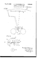
Fig. 5 is a horizontal section taken substantially along line B-l of Fig. 3:
Fig. 6 is a atic representation o! the optical system embodied in the apparatus of the preceding iigures; L
Fig. 7 is a diagrammatic representation o! the electrical system embodied in the apparatus of the preceding figures;
Fig. 8 isan axial cross section of a magnetic clutch;
Pig. 9 is an axial cross section of a one-.turn clutch mechanism Figures 10 and 11 are sections taken substantially along lines IU-III and il-ll of Fig. 9:
Fig. 12 is a horizontal section of a switch la Fig. 13 is a vertical section taken substantially along line ll-ll oi' Fig. 12;
14 is an enlarged fragmentary view of a scanner belt:
Fig. 15 is ar enlar optical system;
Belmont. and John L.
Mass
ged diagrammatic view of an liiig.` 16 is a top plan view of a counter: i Y I y Fig. 17 is an end elevation of the counter oi Pig. 16; llig.4 18 is a. side elevation oi the "counter .oi 28 Fig. 16. certain parts being broken away; f Fig. 19 is a cross section taken substantially on line `-I! of Figures 16 and 17;
Fig. 20 is an id F1a 16: 1
Fig. 21 is' a diagrammatic view similar to Fig. B. illustrating another embodiment oi' the invention; Fig. 22 is a front elevation of a reiiector usedin eal section oi' the counter of continuous one; and the provision oi apparatus ot the class described which is simple to operate and which yields results of an inherent high accuracy-. Other objects will be in part obvious and in Dart pointed out hereinafter.
The invention accordingly comprises the elements and combinations oi' elements, and features y oi construction and operation,.which will be exempiided in the apparatus hereinafter described, and the scope oi the application oi which'will be indicated in the following claims.
In the accompanying dras, in 'which illustrated several embodiments oi the present invention,
Fig. l ls a iront elevation of t i measuring apparatus built in accordance with the present invention;
Fig'. 2 is an enlarged fragment oi Fig. l;
Fig. 3 is an end elevation 'oi the apparatus shown in Fig. 2;
Fig. i is a horizontal section taken substantially along line i-t oi Fig. d;
|i:liel"ig.21mbodiment; Fig. 33 is a vertical section taken substantially 3g 'along line 23-23 oi Fig. 22;
Hg. 24 is a horizontaieotion taken substan tially along line 24-24 o! Fig. 22; Fig. 25 is a diagrammatic viewV similar to Fig. 6,
illustrating stil tion;
another embodiment ot the inven- FigeZil isa fragmentary elevation ot abank of photosensitive tubes used in the Eig. 25 embodiment;
Fig. 2'lhis a diagrammatic front elevation of a bank ot photosensitive devices alternative to the showing of Fig. 26; Fig. 28 is a diagrammatic view similar to Iilg. 8,
` illustrating still another embodiment oi the invention: 50 Il'ig.'` 29 is a diagrammatic iront elevation of a -1 reiiector assembly used in the Fig. 28 embodiment;
Fig. 30 is a section taken substantially along line 3l-3l of F18. 28,' illustrating a light chopper disc: n
Fig. 3i is a front elevation of another embodiment of the invention;
Fig. 32 is a vertical section along line 82--32 of Fig. 31;
Fig. 33 is a vertical section taken along line 33-33 of Fig. 32; l
Fig. 34 is an enlarged fragmentary front elevation of a scanner embodiment;
taken substantially substantially Fig. 35 is an enlarged vertical section taken substantially along Fig. 36 is a side line 35-35 of Fig. l34;
Fig. 37 is a top plan view of the embodiment of Fig. 36; g
Fig. 38 is a diagrammatic fragmentary front elevation of the embodiment of Fig. 36, taken. substantially as indicated vby line 38-38 in Figures 36 and 37; I
Fig. 39 isanother matic fragment-,aryv
front elevation of the taken substantially as of Figures 36 and 37; and,
' Fig; 40 is an enlarged of a scanner: belt used in the Fig. 36.
embodiment of Fig. 36,
embodiment of Similar reference characters indicate corre-n spending parts throughout the several views of the drawings.
One method heretofore proposed for` the measurement oiv the area of work piecesv by photoelectric methods'comprises scanning the work piece with successive beams of light that are rerlected to a photosensitive device so that the dei vice responds differently tovreiiected light from the work piece as contrasted to reflected light from its background, and then integrating the responses with the rate of travel ofthe scanning beam across the `work to obtain an expression of area of the workpiece. A dimculty with this has been that it is limited by the character of the scanning apparatus available.
ing on its axis, and provided with a spiral ar-v rangement of holes near its periphery, through which holes the scanning light beam is projected. The rotation of the disc causes scanning beam to traverse one dimension, while successive holes provide for successive beams which, taken as a bundle, traverse the other d:lmansion. With this type of scanning device, the integrating mechanism has been coupled to the rotating discfor rotation therewith, on the supposition that the .angular displacement of the scanning disc was a true linear function of the rate of travel of the spot of light caused by the interception of the scanning beam by the work piece. -It can, however, be proved-that this supposition is not geometrically true, because the rate of travel of the spot across the work depends of travel of the light spot, and an integrating the disc does not record trueareas. The error, further, is not constant, as a single work piece placed to cover one part or an inspected field will give one arco reading,
mechanism coupled to frame `used `in the Fig. 3i
. elevation of another embodi-A ment of the invention;
indicated by line 38 fragmentary plan view method of measurementv 'The only scanning device heretofore suggested for this Y of such increments of the projected of each increment.
give a true expression. ofthe area of the workY piece, regardless of what position it occupies in V,to provide an area measuring system of the scanforegoing errors are not` the inspected field. Several embodiments of such systems are shown in the drawings, and described hereinafter.
A further disadvantage of the scanning type of l area'measuring systems that they make no provision for the automatic measuring of a succession of work pieces. They require, for example, that a work piece be manually placed in the inspected field, measured, :nd
.manually removed from the held before another heretofore proposed isA piece can be measured. Commercial operations. l
do not ordinarily permit so time-consuming a procedure. A further principal object of the invention, accordingly, is to provide the measuring system with automatic means for presenting, measuringand withdrawing'a rapid succession of work pieces. A
Since an important commercial use of the invention is in the measurement of leather, tanned skins, andthe likejthe invention is here disclosed as embodiedin machines adapted more especially for this purpose. trated are designed to practice a method which may be'described briefly as embodying the steps of Ymoving a beam ments of area arranged in an orderly fashion convenient for scanning. In the case of the known area above referred to, the scanning operation detects the presence of those increments not covered by the work, and these increments are counted. Since the function of the scanning beam is to determine whether-'or notl successive increments are covered, it obviously is not essential thatthe scanning beam cover the entire area these increments of area. are represented by the The machines illuss of light across a known area in which the surface to be measured is interposed,
to scan increments of said i a multitude of incre- Assuming, for example, that spaces in coordinate or quadrille paper, the beam may be made equal to the width of a row of these spaces and may sweep across the entire row, but it will perform essentially it is considerably vsmaller than the width of such a row and sweeps across the center line oi the row. In either event the beam will scan successive spaoes in the row, and by usinga suitable detector with it, it can be made to tellwhich spaces are covered by the work. The word the same function if4 4or increment be as narrow as conveniently pos sible, because the narrower the path, the smaller will be lthe error introduced bythe terminal ehect of the work piece. By terminal effect is meant that small edge fragment of the work piece that overlaps the scanned path a small distance insumeient to record on the photosensiuve devise, the area of which is therefore not counted', or l which overlaps the scanned path sulcientiy to be counted, but insumciently actually to repre; sent the area indicated by the count. Y
For the purposes of simplicity, the apparatus'. of the first embodiment of the present invention may be considered as made up of a work feeding mechanism, a scanning system (comprising a beam projector and a beam reflector or interceptor), a scanning system feeding mechanism, a detection system. and an integrating system givina expressions of area as an end` result.- These various portions oi the apparatus will be separately described, and then correlated in the description oi the operation of the apparatus as a whole.
'Work feeding mechanism The work ieedimi,r mechanism of the present invention is sho in Figures i. 2, and 3. Rec- .:i 1v f .iler frames l, oi` wood or metal or other suitable material, are provided for each of the hides i to 4be measured. The hides 3 are attached to the frames l by strings t, a. mul/fplicity of which are provided around the interior edge oi the frame to take .care of dilerent sizes und shapes of hides. The strings d stretch the hide t so that its maximum surface area. is pre- 1 sented to the front of the frame.
In other Words, the hide is stretched so that its plane is in the plane of the frame. The frames i are commonly provided in tanneries for stretching the hides 3 during their tanning,- and hence the positioning of the hides i on the frames i ordinarily requires no additional work,
'The spacing of the Numerals 'l and 9 indicate, respectively, horlsontal slides or tracks in which the frames I are vertically positioned. r)Both slides 1 and 9 have channeled cross-sections (see. Fig. 3), the channel of `the lower slide 'l facing upwardly while the channel oi the upper slide 9 faces downwardly. The slides l and 9 are of considarable length, and are supported in spaced relation (by means omitted from the drawings for the se oi clarity) such that the frames l slide f6' freely therebetween, but are nevertheless accurately positioned in a preferably vertical plane.
Numeral il indicates an endless chain belt which is supported by sprocket wheels i3 and i5 at its ends. Intermediate idler sprocket wheels (not shown) may be provided for preventing the upper lap oi the chain ll from sagging, or. the upper lap may travel in a channel or, for exampie, on top of the slide l-as shown. At'suitably smced intervals, the chain 4vvitl'i does il which extend belt il isprovlded over the slide l im edgeof a hide frame l. dogs il will be indicatedV Position to abut the hereinafter. A
On the same shalt that supports the sprocket wheel it there, is mounted a second sprocket in Fig. i. The does engage.
- having front tracks 39. The tracks tu are in other directions.
The optical or lens system 5I may best be delenses 65 and di is orhid'e 3. It will xthat also passes over a sprocket wheel 23 on a main drive shaft 25. Suitable motivating force is provided for the main'drive shaft 2t, so that the belt H is driven from the sprocket wheel I3. The direction of rotation is such that thenpper lap of the belt il moves from the right to the left Il of the belt Il thus propel along the slides 1 and 8 whatever frames i they Scanning system f The scanning systemof the present invention is shown in Figures 1, 2. 3; 4, 5, 6, 7, 14, and 15. Its supporting mechanism will first be described.
Numeral 2l `(Figures 2 and 3) indicates a car- I 'iage that comprises a hollow rectangular frameand back pieces 29 and 3|, respectively, and ends, thefiront and back pieces 29 and 3i are provided with bearing extensions 35 which rotatably support iianged wheels 3l that run on disposed parallel to the slides l and t of the work feeding mechanism. The carriage 2l is moved by the scanning system feeding mechanism hereinafter to be described.-
The front piece 29 jector means, while the beam reilcctor means.
Mounted on the front `piece 2d at its extreme ends are a pair of upstandlng pillars or posts All. The posts 4l are deslrably braced to the cross pieces i3 by struts di. A horizontal shell W is supportedon the posts di somewhat below the upper ends thereof, and a parallel shelf' t? is provided at the upper ends of the posts di. The shelves ib and di support the beam projector mechanism, which generally comprise a light source 49, an optical or lens system indicated generally by numeral 5l, and a scanning device forming aparticular feature oi' the present invention. Y
The light source 49 may comprise an incandescentllament bulboi' theconcentrated illament type. as usually used for projection equipment, or any other vsource of sufllcient area and intensity. It is so mounted (on a block 53) that its illament is positioned midway, vertically, between the upper and lower inner edges of the work-supporting frame l. It is preferably shielded. or provided with a yreflector system such as used in small motion picture projectors. As little stray light as possible is-allowed to escape supports the beam pro back piece il supports the scribed by reference `to Figures 6 and 15. It comprises a lens 55, which throws an image oi the source @il on a second lens 5.1. Between the positioned a scanner belt 59, to be described infgreater detail hereinafter. The second lens 6l ordinarily throws an image of a hole in the scanner belt 58 on the work piece be understood that either one or both oi' the lenses 55 and 5l may be. and frequently are, compound lens systems in themselves. The lenses 55 and 51 are mounted in position on .the block 53, and are desirably-provided with focusing means so that they can be adjusted to optimum positions with relation to the light source 4B, the scanner belt 59. and the work piece' 3,- prior to actual measuring opera-v side pieces 33. At their extreme dii . the hole B5 on frame I rearwardly projected by the lens 51 on the mask 6I. This mask 6I provides a cut-off for scanning beams, limiting their travel to dimensions inside the frame I. The mask 6I is preferably mounted directly on the lens 55, and the entire system is arranged so that the scanner belt 59 is as close to the maskl 6I as practically feasible.
The scanner belt 59 is in the form of a. thin 'endless band of flexible material. The material may, for example, be steel of a thickness not greatly exceeding the order of 0.005 inch. The width of the belt 59 depends upon many factors, such as the area to be scanned (the area of the frames I), the width of the scanned paths across the work, and the lens system employed. However, for a frame size of ve by seven feet, which is suitable for practically all hides, the belt 59 may conveniently be of width as ordinary commercial motion picture film 35 millimeter). The edges of the belt 59 are provided with sprocket holes 93 (see Fig. 14), in this respect also resembling motion picture film. The length of the belt 59 is determined by many fac-r tors including its rate of travel, the lens system employed, and the desired width of the scanned paths across the work piece. The belt 59 is punctured or perforated with a series of holes 65 along its length, the holes 65 being arranged on gradually sloping lines so that the complete band, of the preferred embodiment, has two complete lines from uppermost hole to lowermost hole. The holes 65, passing between the lenses 55 and 51, determine beams of light which are the scanning beams of the invention. As a given hole 65 passes through the lens system, it defines a beam that moves across the work piece 3 at a vertical height determined by the location of the belt 59, with respect to the in a horizontal with the belt,
As one beam hole lens system, which beam moves straight line, since the hole itself, moves in a horizontal straight line. completes its traverse of the frame I, a next 65 is brought into the lens system, another beam which is vertically just above or just below the preceding beam, depending upon the direction of movement of the belt 59. From this brief description of the operation of the de vice, it will be seen that the positioning of the holes 65 on the belt 59 is determined by the character of the scanning work to be the assumed frame size of five by seven horizontal distance between holes 65 (dimension b in Fig. 14) will need to be the length of the image of a five-foot line at the frame I projected by the lens 51 on the belt 59. Assuming that the lens 51 is a projector lens having an opening of f 1.9 and a focal length of 25 millimeters, and the 'frame I to be ten feet from lthe `lens 51, this dimension works out to about 0.5
inch. The vertical distance between a topmost hole and a lowermost hole 65 of a preceding series of holesA (dimension a in to be the length of the image of a seven-foot line, which, with the same system, works out to be about 0.7 inch. The vertical distance between adjacent holes 0E (dimension c in Fig. 14) depends primarily upon the number of scanning lines to be included in the vertical length of the frame I. If one scanning line is determined to be one inch wide, then a total of eighty-four lines will be needed for seven feet, and eighty-four lines will require eighty-four holes 85 spaced equally within the overall dimension a, which works out, in the foregoing example, as one one done. With 4 feet, the
Fig. 14) will hundred and twentieth of an inch. By analogous reasoning, each hoie65 should be not greater than one one hundred and twentieth of an inch in diameter, or the scanned paths on the work will overlap vertically.
Some of the dimensions in Fig. 14 have been exaggerated for clarity, and are not to be considered proportional to the dimensions actually used.
The reason for the extreme thinness desired in the belt 59 is now more apparent. If a thick band were used, the opening 65 as it passed farther from the optical center of the system would tend to present more and more an eliptical opening for the scanning beam to traverse, the limit ing condition being the absolute eclipse of the beam. At the least, this would mean that the spot of light produced on the work would be weaker towards the peripherles of the work, which would be undesirable in connection with the photosensitive device employed. A thin belt, however, reduces such eclipsing to a disregardable amount.
The supporting means for the belt 58 will next be described. Numerals 31 and 69 (Figindicate drums which are 1I and 13, respectively. The drums 61 and 69 each are provided with flanges at their outer edges, which tend to guide the belt 59 into proper vertical position, and with projections about their peripheries which mesh with the openings E3 along the edges of the belt 50. The lower end of the shaft 1I is supported in a geared transmission 15 which is mounted on the shelf 5. The transmission 15 is of customary construction. A motor 11 is suspended from the under side of the shelf 45, its shaft projecting into the other end of the gear train of the transmission 15 1I (and hence drum 61) to rotate, through the transmission 15. The transmission 15 provides that the drum 61 will rotate at the proper speed, which is usually much lower than the speed of rotation of the motor 11. The upper end of shaft 1I is supported in a single-turn clutch 19, to be described in connection with the integrating mechanism. l
The lower end of shaft 13 is mounted in a bearing 8| on shelf t5. The upper end of shaft 13 is supported in a gear multiplier box 83, likewisev to be described in connection with the integrating mechanism.
A pair of sprocket wheels B5 and 81 are mounted on shafts 1I and 13, respectively, lust below the drums 61 and 69. A link belt 89 connects the sprocket wheels B5 and 81. 'Ihis arrangement provides that the shaft 1I drives the shaft 13, and since wheels 85 and 81 are of identical size, the drums 51 and 59 rotate at identical speeds. This direct drive of shaft 13 from shaft 1I releases driving tension that might otherwise be disadvantageously placed in the scanner belt |59.
In order to prevent whipping of the belt 59 as it passes between the lenses 55 and 51 (which might lead to imperfect focusing) aligning idler rollers 9i and 93 (Figures 4 and 15) are provided to position the belt 59. The rear rollers 9| are on fixed pivots, and determine the placement of the belt 59, while the front rollers 93 are preferably spring-pressed to hold the belt 59 against the rear rollers 9|.
The beam reflector means heretofore referred to is supported by means of vertical standards 95 (see Fig. 3) mounted on the rear piece 3| of the carriage 21. The rear piece 3|, it will in order to drive the shaftl arcaico] A be seen, is positioned behind the slides 1 and l, and is thus behind the ,frame I and work piece 8. However, this spacing is desirably made as close as conveniently possible.v The reflector per se of the present embodiment of the Invert-- tion comprises a spherical mirror 01, the geometrical center of which 'is approximately the 's irably provided to reinforce 'the standards Il, n and a sufficient number' of' crossv bars between the standards 95 aidtc support the mirror l1.` .l The mirror 91 may b e oflny suitable type,
'optical center of the forward lens 51. Forthe dimensional example heretofore given, a mirrorradius of a little over ten feet is satisfactory. The. `specular orreilectlng side of the mirror 01, of`
course, faces the lens Il." Trusses il are de-v and need not be made allfin one-piece.4 Per-: hansl the moet mirror for use in' connection with the. present'invention, however, is a spunI specula'rlyfpolished aluminum mirror.
' nearing atan tormentas seran 'the purpose of the mirror 91 isl to reilect back light beams issuing from the lens l1 approxi the apparatus provides means for moving the waybetween the lens-l1 cell III.-
Soanninp system 'feeding AmechanismV f if the scanning system just vdescribed were held stationary while the work` l moved past it on the slides i and 8, it is `apparent that no area measurement could be accomplished. Therefore ning system with the work until the givenA work piece is measured; after which thev scanning system is moved backn to commencenimr-` lng forward vwith a subsequent work piece. Referring again to Figures 1, 2, and 3, it-will l be seen that a stationary base-I is provided,v
'aft-25., 2 Sprocket wheels i118, 2 3, IIS, 'IIl5,'iI|', and/- i', im are all the same size. It isaccordinglyjse'en tt the vupper lap of chain belt III will move inthe same direction. and at speed, as chain belt il.
i ila. endless chain belt IIS passes over the 'secondspmktwneq'lu 0g the :dm-e lFor theepresent embodiment, the cell IUI may.
ing sin m (Figuras 2 ands) which nts sndabiy 1 into a slot lill in the middle of the front piece .it of the carriage 21. An upwardV extension valong with it. Provided the pin |25 is on the upon the ends of which are mounted bearing brackets |105 and |01 rotatably supporting'shaft's' ldd and iii respectively. The shaftjll! carries a pair of sprocket wheels il! and'II.- The shaft iii carries a sprocket wheel II'I, which is pcsiticnedin the plane of the sprocket wheel wheels iii and H1. The-belt III is'positioned as-close aspbssible to the front piece 20 of the' scaer' mechanism carriage 21.A Another chain belt i2l passes over the lsprocket wheel I I3 and precisely the same n -belt iis lcarries a sidewardlymrojectit@ is'providecl in the front piece 29 in vorder that the slot i211 may. extend upwardly to the y level of the upperlap of belt Ill. The`slot iii extends downwardly as low as thelower lap of chain belt H9. It will now be seen that, as` chain beit i i9 moves, it carries the carriage 21 upper lap. the carriage 21 will move with the beit ii, and hence with the belt il and the ceeding work piece.
" "rae -detention work piece a. 'as the cnam m'moves 'at a uniform velocity, so will the carriage 21 move with a uniform velocity, until It reaches the ends -where the chain belt II9 is in contact with its sprocket wheels III and II'I, at which time the .carriage will move 'at a varying speed because the pin I 2i will have a vertical as well-asa horizontal' component of movement. When the pin -1 I2! is on thelower lap of the belt IIB, the car- 4ringe 21 willi move against the belt' II,'and the work I.' During thisphase the carriage is being" returned toperform the measurement ofa luc- By means'to be described hereinafter, the en? -tire arca measurement of a given work piece is' accomplished while the carriage 21 is moving `with the work '3. While the scanner belt runs continuously, no area measuring is done while the carriage is going throughreverse movement, or through non-linear movement at either fendof its travel.
vIt will now beseen that, for proper` operation. the frames I must be spaced on the slides 1 and l at intervals such that the leading edges of each succeeding irameare separated by a dis-- tance equal to the entire length of chain 4belt lli. This positioning Is` achieved byv properly positioning the dogs Il-onthechainbelt II. It will now also-be seen thatthe tracks )I for the carriage- 21 must extend a distance beyond each end of thebase Il# 'at least equal,
to, and preferably a few inches more than, half the width of the carriage front piece 29. in order t l to support the carriage 21 throughout its entire Detectionsyst-emv The 'lphotosensitive"devicefll may be any one,
system of the present invention isbased upon the operation of the photosensitive device IIII, and is subject to wide modification.' 'as' will be apparent in the descriptions of modifi# cations vgiven hereinafter. In the present em" bodiment, the detection .system lcomprises the 'photosensitive device IIN, and an electrical amf plifier III and relay In. both of which are mounted, for example,- on the top of shelf 41. (see, viilgiires2su1d3). i
of the types currently available, such as photoelectric cells, electron multipliers, bolometers. and
the like. If certaintypes of photoelectric cells? I 'are usedl then for most' successful amplification of the impulses received,l the light source should fbe of an intermittent character. The provision of intermittent light is described in connectionv with the modifications to appear hereinafter.
for examplel be a Weston,Photronic cell, in which event an intermittent light source is not needed. A
.The cell III is placed, as has been indicated, as` nearly as possible to the focal "point of rays reflected from the mirror 91. This means that so long as any scanningv ray is not intercepted by the work piece 3, it will be reflected to and actuate the cell IDI. If no work piece is present, a" complete scan will cause the cell to be constantly energized, audit will develop a continuous current for a. time equal to the time taken for the I scanning beams' to traverse the entire presented surface of the mirror. l1. When a work piece 3 is interposed before the mirror 91, however, duryso little light will be reflected that, by adjusting l. 't aladino the cats of the amplifier |3| and the relay W8, its effect mawhedisregarded) and hence the output current in the relay circuit will be stopped. The time that the output current is stopped rep- -esente accurately the area of the work piece. This area is determined and recorded by the in tegrating system tobe described.
The characteristics of the ampliner |3| vary with the type of the photosensitive device used, 'itl and are well known for each such device. The construction of the relay |33 is also well known and need not be described herein. The function of the relay |33 of the present embodiment is to hold an exterior circuit open so long as light falls the photosensitive device |31, but to close said .terior circuit the instant the light ceases to fall lathe photosensitive device, or diminishes below ascertain level.
Integrating system a Since the scanning beams of the present invention travel in straight equidistant, parallel lines, 'and since all scanning beams travel across the scanned surface at the same uniform speed (uniu form both as to the speed of a single beam while traversing .the surface scanned, and as to the speed of the several beams taken with relation to meh other), the total time that all the scanning of one complete measurement are inter- 4, cepted by the work piece is an accurate expresnon of the area of the piece. The integrating mechanism of the present invention is accordingly designed to compute and express this total time, and in addition to provide means to assure that a single work piece is not measured more s than once.
The speed of rotation of either one of the drums H* and 55 is an accurate expression of the speed of ent of the scanning beams, for the forem reasons. Therefore the integrating syss mi of the present invention is operated, in one by the shaft 13 of drum 69. Shaft 13 and drives a multiplier gear 83, which is of .standard construction, and which delivers the imme of shaft 13 at a higher but proportional "v sucedio a countershaft |35 at right-angles to the Mt 13 (see Figures 2, 5, and 7)'. The counter- 35 drives an electro-magnetic clutch |31,
winch is shown in greater detail in Fig. 8. The
:la: avt |35 is the drive shaft for this mech- I", and has a driving disc |39 secured fast on i3. the shaft |35 being mounted in ball bearings. driven shaft |4| is also mounted in ball bearff'i-.: 1 and is supported coaxially with the shaft |35. Thedriven shaft |4| carries a rotor |43. All of this mechanism is mounted within a stationary or casing. The rotor |43 is provided with two conical surfaces |45 and |41, one of which is arranged to engage a complemental sur- |43 on the housing and normally is held in with it by a spiral spring |I. Thus the surface |45 acts as a brake, and since there is no power tending to drive shaft |4| when it is thus braked, the rotor |43 is held stationary.
At one end of the casing is an electro-magnet wf comprising a stationary coil |53 and an armature |55 mounted at the end of said coil and normally heid away from it by three coiled springs, one of which is shown at numeral |51. The armature |55 has a loose engagement with a sleeve |59 N threaded on a bushing in which the ball bearings are mounted for supporting the shaft |4|. When coil |53 is energized, it moves armature |55 to the right, and this movement produces a correding movement of the bushing |5| to the i! right, together with the bearings mounted therein, the shaft m, and the rotor m. Adjusting screws, one of which is shown at numeral |83, serve to limit thev extent of this movement, and it is made of suchen amplitude that the conical surface |41 of rotor |43 engages the comple mental surface of driven disc |33 and establishes a driving connection between shafts and MI.
gether, so that their rotation is coextensivc.
Shaft |4| is required to move longitudinally with. the movements of the clutch, but shaft is lon'- gitudinally stationary.
Shaft is carried in a bearing 131.(Flgures 2 and 5) which is arranged to -prevent its longitun dinal movement. The opposite end of shaft |35 carries a pinion |53, .which actuates the driving pinions 11| and |13 of counters |15 and |11, respectively. The counters |15 and 11 are mounted on a bracket |13 (see also Fig. 3) which s is in turn mounted on the under side of shelf 41. The upper counter |15 totalizes the measured areas of all work pieces passing the device. The lower counter |11 totalizes only the area of each individual work piece, and is then manually 'a or automatically returned to zero for the next work piece. The counters may be controlled (as by the ratio -in the gear multiplier box 53, and the ratio of the sizes of pinions |59, |1|, and |13) to read area directly in whatever dimension (such as square inches or square feet) that is desired.
While the counters |15 and |11 may be any of the commercially-available continuous revolution counters, it has been found advisable, from the standpoint of the accuracy with which the counters are read, to use a modified form of commercial ratchet counter that is novel with the present invention, This modified form is shown in lilglures 1s, r1, 1a, 19, and 2o or the drawings, "to which reference is now directed.
The ordinary commercial counter, which is used as a whole in this modified form, isindicated at numeral 219. A difficulty encountered when using these counters is that, at the completion of a counting operation such as is involved 'u in the measurement of areas by the methods herein described, the last digit disc of the counter (indicated by numeral 28| in Fig. 16), is frequently at a position intermediate two digits (such asv the 3 and "4 indicated in Fig. 16). u The structure ofthe counter is such that the relative position of intermediacy cannot readily be estimated; for example, in Fig. 16, it is not possible to say with accuracy that the counter reads 783.3, "783.4", 783.5, 783.6, or 783.7. The present modified counter makes it possible to read the commercial counter, in such situations, to an accuracy represented by one, and possiblyl two more digits.
' The structure of the commercial counter indi- 05 cated at numeral 219 is such that it is driven by rotatable shaft 283 (see Figures 19 and 20). In the present modification, this shaft is not, however, directly coupled to the shaft (such as the shafts of driving pinions |1| and |13) the rota- 70 tion of which it is desired to measure;
, 184,169 i7 upon which rotates a cup-shaped enclosing-meinof the same size, so that the shaft 29H thus drie her its. 'Ihe cup 2l@ is cylindrical, and through Athe countershaft 233 in a one to one rotation. it, on its axis, passes the main drive shaft 29| the However, i! the knob 285 is `forced inwardly rotation of which it is desired to measure. The against the counter 218, the inner face of the io portion 295. which forms a part thereof. Around the cup 289 is 110W rotated. it drives the eollnter- 10 ,15 'by the engagement of a projection 293 on the lIn operation, the cup 2l! is not molested until 16 "I engaged.
' counter 219 when the projections 283 and 30| are represent the extent that the counter had origi- I nteriorly oi' the cup 283, the countershatt 203 .referring again to Fis. 16, if, after rotating the carries a pinion 303, which has a concaveconical CUP 239 so as to brins up the digit "3 on the clutch face 305 at its outer end. The pinion 303 18st digit disc of the counter 218 into full posiis free to rotate on the shaft 203. The shaft 283 tien, the cup indicia (on a scale of one hundred) n also carries a splined, but longitudinally movable read 55", then Cheltllle reading 0f the counter 30 clutch 0011m- 301 having a mmm; face nl at the termination o! the count was "783.55. adapted to engage the face 305 of the pinion 303, After this determine-$1011. the spring 29'! returns and a similar oppositely-faclng conical face :Il the cup 289 toits zero position for another count. at its other end 0n the end 0f shaft zu 15, Itisthusseen that the comercial counter 218 "U mounted a second pinion 3|3 having an inward is modified by the provision of a. vernier device s concave conical face 3l! adapted to engage race 'that een be placed into operation at will, and the ein of collar al1. The second pinion m is also accuracy of the counter 219. so fer es its reading free to rotate on the shaft 233. The longitudinal iS C0nce1l1ed. is thus greatly enhanced. spacing of pinion 303. collar 301, and' pinion :la It will be recalled thatvthe scanning belt 59 has 4o is suon that the oonar m may be moved intoenbeen deeonbed es continuously moving, and since '4o sagement with either pinion, but not with. both fille light source 48 is also continuously burning. at the same time. f
-IU 323. The lower end of lever 323 slidesin asroove 'The circumference cf cach drum 5" and 39 iS 60 longitudinally in the bracket 205. The pin 329 celled that the scanning belt was described as `I6 extends forwardly to terminate as a head m that Containing two complete series or scanning holes ass is closely juxtaposed to the nner face of cup Q 65. This diametrical relation of the drums t1 A compression spring 335 reacts on the pin 329 and 69 means that one rotation of either drum so as to tend to maintain it in its forwardly ex- Will represent s Complete sean 0f a given work tended position. Piece Means (comprising the one-turn clutch 'n Numeral 331 indicates a gear that is mounted mechanism 79 heretofore indicated) are accord- B0 on the inner face of cup 299, concentric with the ingly provided for rendering the photosensitive Shaft nl but unattached therem The gear 331 cell 0| ineffective to control the electro-magnetic rotation with the pinion 339 is a pinion 34| which d: um s1 for any one Work piece 3- 5 meshes with the pinion 3|3 on shaft 283.
inner cam member |8| ismounted for rota` 70 tion, the pinion 303 drives shaft 283, and is in 'I'he cam member |8| has a. cylindrical portion turn driven directly by shaft 29| through pinions |81, on which frictionally rotates a second sleeve s 3H and M9. The pinions 303 and 3| 1 are both |89. The sleeve |39 has a. cylindricai retainer 1E
Priority Applications (1)
| Application Number | Priority Date | Filing Date | Title |
|---|---|---|---|
| US90260A US2184159A (en) | 1936-07-11 | 1936-07-11 | Apparatus for measuring area |
Applications Claiming Priority (1)
| Application Number | Priority Date | Filing Date | Title |
|---|---|---|---|
| US90260A US2184159A (en) | 1936-07-11 | 1936-07-11 | Apparatus for measuring area |
Publications (1)
| Publication Number | Publication Date |
|---|---|
| US2184159A true US2184159A (en) | 1939-12-19 |
Family
ID=22222002
Family Applications (1)
| Application Number | Title | Priority Date | Filing Date |
|---|---|---|---|
| US90260A Expired - Lifetime US2184159A (en) | 1936-07-11 | 1936-07-11 | Apparatus for measuring area |
Country Status (1)
| Country | Link |
|---|---|
| US (1) | US2184159A (en) |
Cited By (16)
| Publication number | Priority date | Publication date | Assignee | Title |
|---|---|---|---|---|
| US2450054A (en) * | 1941-08-25 | 1948-09-28 | United Shoe Machinery Corp | Area measuring machine using light beams |
| US2561406A (en) * | 1949-02-04 | 1951-07-24 | American Can Co | Apparatus for inspecting articles with a movable spot of radiant energy |
| US2626989A (en) * | 1948-10-28 | 1953-01-27 | Albert A Brown | Comparative photometer |
| US2649500A (en) * | 1949-12-16 | 1953-08-18 | Owens Illinois Glass Co | Inspecting apparatus |
| US2753459A (en) * | 1956-07-03 | Inspecting interior surfaces of glass | ||
| US2862415A (en) * | 1954-08-12 | 1958-12-02 | Harry A Kuljian | Particle counting optical apparatus |
| US2959348A (en) * | 1953-06-26 | 1960-11-08 | Bayer Ag | Apparatus for the automatic counting and determining particle size distribution |
| US2968210A (en) * | 1957-08-08 | 1961-01-17 | Pillsbury Co | Electro-optical apparatus for measuring volumes of solids |
| US3026766A (en) * | 1957-08-14 | 1962-03-27 | Photoronix Inc | Apparatus for measuring and recording terrain data |
| US3074631A (en) * | 1959-06-04 | 1963-01-22 | Krantz Sohne H | Thread counting device |
| US3096443A (en) * | 1960-06-20 | 1963-07-02 | Jones & Laughlin Steel Corp | Electronic surface inspection system |
| US3297873A (en) * | 1963-12-30 | 1967-01-10 | Avco Corp | Microscope system with means for viewing the entire image and means for measuring radiation from a selected segment of image |
| US3456118A (en) * | 1965-07-30 | 1969-07-15 | Buckbee Mears Co | Carriage with movable co-planar frames for positioning test devices with respect to continuously moving strip of metal |
| US4360887A (en) * | 1979-08-04 | 1982-11-23 | Edward Wilson & Son Limited | Skin categorizing apparatus |
| US4984073A (en) * | 1954-12-24 | 1991-01-08 | Lemelson Jerome H | Methods and systems for scanning and inspecting images |
| US5283641A (en) * | 1954-12-24 | 1994-02-01 | Lemelson Jerome H | Apparatus and methods for automated analysis |
-
1936
- 1936-07-11 US US90260A patent/US2184159A/en not_active Expired - Lifetime
Cited By (17)
| Publication number | Priority date | Publication date | Assignee | Title |
|---|---|---|---|---|
| US2753459A (en) * | 1956-07-03 | Inspecting interior surfaces of glass | ||
| US2450054A (en) * | 1941-08-25 | 1948-09-28 | United Shoe Machinery Corp | Area measuring machine using light beams |
| US2626989A (en) * | 1948-10-28 | 1953-01-27 | Albert A Brown | Comparative photometer |
| US2561406A (en) * | 1949-02-04 | 1951-07-24 | American Can Co | Apparatus for inspecting articles with a movable spot of radiant energy |
| US2649500A (en) * | 1949-12-16 | 1953-08-18 | Owens Illinois Glass Co | Inspecting apparatus |
| US2959348A (en) * | 1953-06-26 | 1960-11-08 | Bayer Ag | Apparatus for the automatic counting and determining particle size distribution |
| US2862415A (en) * | 1954-08-12 | 1958-12-02 | Harry A Kuljian | Particle counting optical apparatus |
| US4984073A (en) * | 1954-12-24 | 1991-01-08 | Lemelson Jerome H | Methods and systems for scanning and inspecting images |
| US5351078A (en) * | 1954-12-24 | 1994-09-27 | Lemelson Medical, Education & Research Foundation Limited Partnership | Apparatus and methods for automated observation of objects |
| US5283641A (en) * | 1954-12-24 | 1994-02-01 | Lemelson Jerome H | Apparatus and methods for automated analysis |
| US2968210A (en) * | 1957-08-08 | 1961-01-17 | Pillsbury Co | Electro-optical apparatus for measuring volumes of solids |
| US3026766A (en) * | 1957-08-14 | 1962-03-27 | Photoronix Inc | Apparatus for measuring and recording terrain data |
| US3074631A (en) * | 1959-06-04 | 1963-01-22 | Krantz Sohne H | Thread counting device |
| US3096443A (en) * | 1960-06-20 | 1963-07-02 | Jones & Laughlin Steel Corp | Electronic surface inspection system |
| US3297873A (en) * | 1963-12-30 | 1967-01-10 | Avco Corp | Microscope system with means for viewing the entire image and means for measuring radiation from a selected segment of image |
| US3456118A (en) * | 1965-07-30 | 1969-07-15 | Buckbee Mears Co | Carriage with movable co-planar frames for positioning test devices with respect to continuously moving strip of metal |
| US4360887A (en) * | 1979-08-04 | 1982-11-23 | Edward Wilson & Son Limited | Skin categorizing apparatus |
Similar Documents
| Publication | Publication Date | Title |
|---|---|---|
| US2184159A (en) | Apparatus for measuring area | |
| US1999023A (en) | Photoelectric comparator | |
| US3240108A (en) | Optical analyzer | |
| US2503808A (en) | Photoelectric automatically balancing polariscope | |
| US3650397A (en) | System for inspecting and classifying objects such as screws, bolts and the like while in motion | |
| US2898801A (en) | Inspection device for detecting differences in two objects | |
| US3724951A (en) | Method and apparatus for determining radiation transmission characteristics of a generally transparent medium | |
| US1799604A (en) | Method and apparatus for identifying crystals | |
| GB1484537A (en) | Apparatus for detecting the nature of or flaws in the surface of a reflecting material | |
| US3827811A (en) | Optical measuring device employing a diaphragm with reflecting surfaces | |
| US2320350A (en) | Camera | |
| US3345120A (en) | Light spot apparatus | |
| US2267961A (en) | Means of testing lenses | |
| US3915551A (en) | Holographic systems using partially overlapping hologram record | |
| US2254548A (en) | Method and means for testing the adjustment of photographic objectives | |
| US3339076A (en) | Dual differential densitometer | |
| US2641956A (en) | Film-perforation pitch gauge | |
| US3807828A (en) | Holographic systems | |
| US3291555A (en) | Photographic reproduction affaratus | |
| US3307020A (en) | High information density data record and readout device | |
| US2230573A (en) | Diascopic projection apparatus | |
| US2822721A (en) | Shutter attachment for high speed cameras | |
| US2169011A (en) | Motion picture apparatus | |
| US3484615A (en) | Photoelectric area measuring apparatus for irregular-shaped plane objects utilizing digital techniques | |
| US3609380A (en) | Radiation sensitive defect scanner for transparent materials |