US2073458A - Sound recording system - Google Patents
Sound recording system Download PDFInfo
- Publication number
- US2073458A US2073458A US724738A US72473834A US2073458A US 2073458 A US2073458 A US 2073458A US 724738 A US724738 A US 724738A US 72473834 A US72473834 A US 72473834A US 2073458 A US2073458 A US 2073458A
- Authority
- US
- United States
- Prior art keywords
- source
- resistor
- circuit
- transformer
- waves
- Prior art date
- Legal status (The legal status is an assumption and is not a legal conclusion. Google has not performed a legal analysis and makes no representation as to the accuracy of the status listed.)
- Expired - Lifetime
Links
Images


Classifications
-
- H—ELECTRICITY
- H04—ELECTRIC COMMUNICATION TECHNIQUE
- H04B—TRANSMISSION
- H04B3/00—Line transmission systems
- H04B3/02—Details
- H04B3/04—Control of transmission; Equalising
Definitions
- Fig. 2 shows in diagrammatic form a recording system in which only certain frequencies of the background sound are diminished
- Fig. 3 shows in diagrammatic form a preferred embodiment of the system shown in Fig. 1;
- Fig. 4 shows in diagrammatic form a preferred embodiment of the system shown in Fig. 2.
- the reproducer l functions as a source of electrical waves varying in accordance with the background sound.
- the reproducer I may be a microphone excited by an original sound, a pickup excited by a mechanical or magnetic record, a photoelectric device excited by light modulated by a record of sound or other similar device.
- the output of the reproducer l is transmitted through an attenuating network 2, and, if desired, an amplifier 3, to a mixing panel 4.
- the reproducer 5 functions as a source of electrical waves varying in accordance with a second sound, such as the dramatic sounds of the action.
- the output of the reproducer 5 is transmitted through an amplifier 5, a second or blocking amplifier 7 to the mixing panel 4.
- the electrical waves from both channels are mixed in the mixing panel 4 in any desired ratio and recorded by the recorder 8.
- a portion of the output of the reproducer 5 is amplified and rectified in the control amplifier 9 and used to increase the attenuation of the network 2 thus reducing the magnitude of the waves corresponding to the background sound during the time that the waves corresponding to the dramatic sounds are being recorded.
- the reproducer 5 may be a microphone excited by an original sound, a pickup excited by a mechanical or magnetic record, a photoelectric device excited by light modulated by a sound record or other similar device.
- the mixing panel 4 and recorder 8 are well known in the art and may be of the type disclosed in an article, The electrical engineering of sound picture systems, by K. F. Morgan and T. E. Shea, published in The Transactions of the American Institute of Electrical Engineers,
- the reproducer I0 functions as a source of electrical waves varying in accordance with the background sound.
- the output of the reproducer I0, suitably amplified, if desired, in the l8, suitably amplified in the amplifiers l9 and 20 is transmitted to the mixer panel IT.
- the combined electrical waves are mixed in the mixer panel [7 and recorded by the recorder 2
- a portion of the output of the reproducer I8 is amplified and rectified in the control amplifier 22 and used to increase the attenuation of the attenuator I6, thus reducing the magnitude of the higher frequency waves corresponding to the background sound during the time that the waves corresponding to the dramatic sounds are being recorded.
- the reproducers l0 and I8 have similar functions to and may be the same type as the reproducers I and 5.
- the mixer panel I! and recorder iii are of known type such as the mixer panel 4 and recorder 8.
- Fig. 3 shows in detail a preferred form of that part of Fig. 1 contained between the dotted lines and having terminals shown by small circles, that is, the reproducer l, attenuator 2, control amplifier 9 and blocking amplifier 1.
- a film 22, carrying a record of the desired background sound is traversed through a beam of light from the source 23.
- the modulated light transmitted through the record 22 to the photosensitive device 24 causes a current to flow from battery 25, through device 24 primary winding of transformer 26, resistors 21 and 28 tobattery 25.
- the variations in this current induce electric waves in the secondary winding of the transformer 26 varying in accordance with the background sound which is transmitted through amplifier 3 to the mixer panel 4 (Fig. 1). r
- the current thus induced in the secondary winding of the transformer 30 flows through the potentiometer 3 I.
- is applied between the cathode and control electrode of the electronic amplifier 32.
- the output of the amplifier 32 is supplied through the transformer 33 to the mixer panel 4, Fig. 1.
- a source of current 34 supplies current to the heater element of the amplifier 32.
- a battery 35 supplies current to the anode circuit of the amplifier 32 through an inductor 36 and the primary winding of the transformer 33. This anode current flowing in the resistor 31 produces a biasing potential which is applied through the resistor 38 to the control electrode of the amplifier 32.
- a portion of the electric waves corresponding to the dramatic sounds flows through the potentiometer 39 and causes a current to fiow in the primary winding of the transformer 40, and induces an electromotive force in the secondary winding of transformer 40 which produces a voltage between the control electrode and the cathode of the amplifier 4!.
- further amplified in the amplifier 42, flows in the primary winding of the transformer 43.
- the current induced in the secondary winding of the transformer 43 is rectified by the rectifying elements 44, 45 and flows through the winding of a relay 46.
- the relay 46 When the relay 46 operates, it closes a circuit from battery 41, through the relay springs 48 and 49, resistor 50 and resistor 28 to battery 41.
- the voltage drop thus produced across the portion of the resistor 28 between the movable contact 5] and ground opposes the electromotive force of the battery 25 and thus reduces the voltage applied to the photosensitive device 24.
- the resistor 52 and capacitor 53 absorb any transients produced by the operation of the relay 4B and thus prevent clicks from being produced in the channel for the background sound.
- the capacitor 54 When the relay 45 operates, the capacitor 54 is charged through the resistor 50.
- the time of operation of the system is controlled largely by the capacitance of the capacitor 54 and to a less degree by the capacitance of the capacitor 55.
- the resistance of the resistor was 5000 ohms
- the capacitance of the capacitor 54 is 3 microfarads and the capacitance of the capacitor 55 is 0.06 microfarad
- the system will operate in about 0.08 second after the relay 46 closes its contacts, but will not restore before about 0.5 second after the relay 46 opens its contacts. This rapid operation and slow restoration renders the change in the background sound less objectionable to the auditors.
- the battery 55 supplies energy to the heaters of the amplifiers 4
- the battery 51 supplies energy to the anode circuits of the amplifiers 4
- and 42 are connected to a tap of the risistors 59 and 60 bridged across the battery 56. Biasing potential is supplied to the 0 control electrode of the amplifier 4
- the resistor 52 stabilizes the operation of the amplifier 4
- the inductors 63, capacitors 54 and 55, with the resistor 66 form a frequency discriminative network which passes the band from about 200 to 2000 cycles and renders the circuit less likely to operate falsely.
- Fig. 4 shows in detail a preferred form of the part of Fig. 2 contained between the dotted lines and having terminals shown by the small circles.
- the blocking amplifier and control amplifier shown in Fig. 4 may be identical with the blocking amplifier and control amplifier shown in Fig. 3. Elements having the same functions. in Figs.
- the electric waves corresponding to the dramatic sounds are transmitted through the blocking amplifier 32 to the mixer panel I1, Fig. 2.
- a portion of the electric waves corresponding to the dramatic sounds is transmitted through the amplifiers 4
- a low frequency current will flow from capacitor 10 along wire 13, upper primary winding of transformer 14, resistor 15, wire 15, springs 11, 18 of key A to capacitor 10.
- This current will induce an electromotive force in the secondary winding of transformer 14 which causes a current to flow from the winding through springs 19 and of key B thence from terminal 8
- the low frequency components will thus be mixed with the waves corresponding to the dramatic sounds.
- the potential difference developed across the inductor 1I will cause a high frequency current to flow through capacitor 85, springs 861' and 81 of key A and resistor 88, and also through resistor 89 and capacitor 90 in parallel, and through resistor 9I.
- the voltage induced in the secondary winding of the transformer 92 is supplied to a pair of amplifiers 93, 94 connected in push-pull.
- Current from the secondary winding of transformer 95 flows through springs 96, 91 of key B, resistor 15 and lower primary winding of transformer 14.
- This current induces an electromotive force in the secondary winding of transformer 14 which causes a current to flow from the winding through springs 19 and 80 of key B, thence from terminal the resistor 9
- the resultant potential difference across the capacitor 10 produced by a low frequency fundamental wave may be out of phase with the resultant potential difference across the inductor 1I produced by a harmonic of this fundamental.
- the phase reversals produced by transformer 92 due to the phase reversals produced by transformer 92,
- is so adjusted to the gain of the amplifiers 93 and 94 that the overall gain is zero, that is, when the relay 46 is not operated,
- , 82 is equal to the amplitude of the high frequency components at the terminals 61, 12.
- a biasing potential is applied to the control electrodes of the amplifiers 93 and 94 from battery I08, throughthe cathodes, resistors IOI-' and I02, resistor I09 and the secondary winding of transformer 92.
- relay 46 When relay 46 operates, current flows from battery H0, through springs 48 and 49, resistor 5 I09 and resistor III back to battery H0. This current will cause a potential difference along resistor I 09. A controllable portion of this potential difference is in series with the battery I 08 and increases the biasing potential on control 10 electrodes of the amplifiers 93 and 94, thus reducing the gain of the amplifiers and the amplitude of the high frequency components at the mixer. The low frequency components are unaffected by this change in gain.
- the resistor H2 and capacitor H3 absorb any transients that might be produced at the contacts of the springs 48 and 49 and thus suppress any clicks due to operation or release of the relay.
- relay 46 When relay 46 operates, a charging current will also flow from battery II 0, through springs 48 and 49 to capacitor H5 and through resistor II I back to battery H0. The rate of change of this current is controlled largely by the resistors I09 and III. The rise of the potential difference along the resistor I 09 will depend largely upon this charging current. The elapsed time after the relay 46 operates before the high frequency current is fully reduced may thus be of the order of 10 to 100 milliseconds.
- the capacitor H5 discharges through the resistor I09 and tends to maintain the large bias on the amplifiers 93 and 94 for an appreciable time, thus prolonging the time before the high frequency components are 5 restored to full amplitude.
- the capacitors H4, H5, H6, H7, H8 may be of increasing capacitance so that the time of restoration may be adjusted.
- the time of restoration can be varied from about 150 milliseconds to nearly 2 seconds. The time of restoration may thus be chosen so as to be most suitable for the type of background sound being recorded.
- a potentiometer resistor I I9 is bridged across 50 the primary winding of the output transformer 95.
- the wiper of this potentiometer is connected through the bias battery to the control electrodes of the amplifiers 93 and 94.
- the impedances presented to the anode-cathode circuits of the amplifier may be balanced to minimize clicks from the operation of relay 46, and distortion of the high frequency components eliminated.
- Adjustment of the wipers on the resistors IOI and I02 assists in the balancing and also reduces the possibility of clicks being introduced into the channel when relay 46 operates.
- the circuit is changed so that an operation of the relay 46 will reduce the amplitude of the entire range of frequencies in the background sound.
- key A When key A is operated, electric waves corresponding to the entire range of frequencies of the background sound flow from terminal 6'! through springs 68, I20, I 2
- the potential developed across the resistor 88 is transmitted through the resistor 89, 9
- the amplified output in the secondary winding of transformer 95 fiows through springs I22 and to terminal 8I,.to the mixer panel II, Fig. 2, thence through terminal 82, springs 83 and I23 back to the transformer 95.
- the relay 46 When the relay 46 operates, the amplitude of all the frequencies in the background sound will be equally reduced.
- the blocking amplifier 32 is inserted in the channel for the waves due to the dramatic sounds to prevent waves from the other channel from feeding back the control device. If the mixer panel be designed so that the loss in feeding back from one channel to the other exceeds say 30 decibels, the blocking amplifier probably can be omitted.
- a source of electrical waves corresponding to a sound a recording device, a circuit for transmitting waves from said source to said device, a portion of said circuit comprising parallel paths, one path transmitting only a predetermined band of frequencies, a second source of electrical waves corresponding to another sound, a second circuit for transmitting waves from said second source to said device and an electronic device in said frequency discriminative path controlled by energy from said second circuit to decrease the transmission efficiency of said path.
- a source of electrical waves corresponding to a sound a recording device, a circuit containing an electronic device for transmitting waves from said source to said device, a second source of electrical waves corresponding to another sound, a second circuit for transmitting waves from said second source to said device, relay means actuated by energy from said second circuit to decrease the transmission emciency of said electronic device, and storage means in the circuit of said electronic device to cause the transmission efliciency of said device to vary rapidly when said relay means operates and to vary slowly when said relay means releases.
- a source of electrical waves corresponding to a sound a recording device, a circuit for transmitting waves from said source to said device, a portion of said circuit comprising parallel paths, one path containing an electronic device, means in said circuit for selecting a predetermined band of frequencies through said electronic device, switching means for disabling at will said selecting means and passing all said electrical waves through said electronic device, a second source of electrical waves corresponding to another sound, a second circuit for transmitting waves from said second source to said recording device, and means controlled by energy from said second source to decrease the transmission efiiciency of said electronic device.
- a source of electrical waves corresponding to a sound a recording device, a circuit for transmitting waves from said source to said device, a second source of electrical waves corresponding to another sound, a second circuit for transmitting waves from said second source to said device, and an electronic device in said first circuit controlled by energy from said second circuit to decrease the transmission efiiciency of said first circuit only for a predetermined band of frequencies which is less than the range of frequencies recorded.
- a source of electrical waves corresponding to a sound a recording device, a circuit for transmitting waves from said source and causing a false operation of" to said device, a portion of said circuit comprisingparallel paths, one path transmitting only a predetermined band of frequencies, an electronic device in said path for transmitting said band of frequencies, a second source of electrical waves corresponding to another sound, a second circuit for transmitting waves from said second source to said device, and relay means actuated by energy from said second circuit to control-the transmission efiiciency of said electronic device.
- a photoelectric cell excited by light modulated in accordance with a signal a device actuated by the output of said cell, a circuit connecting said cell and said device and containing a transformer, a source of potential anda resistor in serialrelation with a winding of said transformer, a second source of potential and a second resistor in serial relation with said first resistor, a source of modulated electric waves and relay means actuated by energy from said source of electric waves to complete a circuit from said second source of potential through said first resistor and reduce the potential applied to said cell.
- a photoelectric cell excited by light modulated in accordance with a signal a device actuated by the output of said cell, a circuit connecting said cell and said device and containing a transformer in serial relation with a capacitor, a source of potential and a resistor in serial relation with a winding of said transformer and in parallel relation with said capacitor, a second source of potential and a second resistor in serial relation with said first resistor, a source of modulated electric waves, and relay means actuated by energy from said source of electric waves to complete a circuit from said second source of potential through said first resistor and reduce the potential applied to said cell.
- a photoelectric cell excited by light modulated in accordance with a signal a device actuated by the output of said cell, a circuit connecting said cell and said device and containing a transformer, a source of potential and a resistor in serial relation with a winding of said transformer, a capacitor in parallel relation with said resistor, a second source of potential and a second resistor in serial relation with said first resistor, a source of modulated electric waves and relay means actuated by energy from said source of electric waves to complete a circuit from said second source of potential through said first resistor and reduce the potential applied to said cell.
- a photoelectric cell excited by light modulated in accordance with a signal a device actuated by the output of said cell, a circuit connecting said cell and said device and containing a transformer in serial relation with a capacitor, a source of potential and a resistor in serial relation with a winding of said output transformer and in parallel relation with said capacitor, a second capacitor in parallel relation with said resistor, a second source of potential and a second resistor in serial relation with said first resistor, a source of modulated electric waves and relay means actuated by energy from said source of electric waves to complete a circuit from said second source of potential through said first resistor and reduce the potential applied to said cell.
- a source of electrical waves corresponding to a sound a recording device, acircuit for transmittingwaves from said source to said device, a frequency discriminative network bridged across said circuit, one portion of said network having a compara tivelyhigh impedance for low frequencies and another portion of said network having a comparatively high impedance for high frequencies, a path from the first portion of said network to an element of a combining network transmitting waves to said recording device, a second path from the second portion of said network to said combining network, said second path containing an electronic device, switching means for, at will, disconnecting said frequency discriminative network and said combining network and passing all said electrical waves through said electronic device, a second source of electrical waves corresponding to another sound, a circuit for transmitting waves from said second source to said recording device, and relay means actuated by energy from said second source to decrease the transmission efiiciency of said electronic device.
- a source of electrical waves corresponding to a sound a recording device, a circuit for transmitting waves from said source to said device, a portion of said circuit comprising parallel paths, one path containing an electronic device having an input and an output circuit and a control electrode, the input circuit receiving electrical waves from said source, and the output circuit supplying electrical waves to said recording device, a source of biasing potential for said control electrode in serial relation with a resistor, an adjustable capacitor in parallel relation with said resistor, a second source of potential in serial relation with said resistor and a second resistor, a second source of electrical waves corresponding to another sound, a circuit for transmitting waves from said second source to said recording device, and relay means actuated by energy from said second source to complete a circuit from said second source of potential through said first resistor and increase the bias on said control electrode.
- a photoelectric cell excited by light modulated in accordance with a signal a circuit for utilizing the output of said cell containing a source of potential for said cell, a source of modulated electric waves, a circuit for utilizing the output from said source, a control circuit energized by energy from said source and containing a rectifying network, and relay means energized by current from said rectifying network to vary the potential applied to said cell.
- a photoelectric cell excited by light modulated in accordance with a signal a device actuated by the output of said cell, a source of potential in serial relation with a resistor for supplying potential to said cell, a source of electric waves, a control circuit energized by waves from said source and containing a rectifying network, a second source of potential, and relay means energized by current from said rectifying network to connect said second source of potential to said resistor to vary the potential applied to said cell.
Description
March 9, 1937. H. c. SILENT. 2,073,458
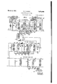
SOUND RECORDING SYSTEM Filed May 9, 1954 3 Sheets-Sheet 1 FIG./
I REP. I ATTENMTOR AMP m:- CONTROL AMPLIFIER I swam/vs AMPLIFIER T 5 6 L (7 41-75mm N [6 CONTROL I AMPLIFIER 22 swam/vs I AMPLIFIER INVENTOR H. C. S/L E N T .mlqdi:
A TTORNEV March 9, 1937. H. c. SILENT 2,073,458
SOUND RECORDING SYSTEM Filed May 9, 1934 3 Sheets-Sheet 2 ATTE/VUA TOR 50 WV I #54 F/G.3 3
CONTROL AMPLIFIER r l 1: V; E 64 65 5 -6 9 E 3 gl :E 6 D Wk I'd-W 6/ 9 60 57 56 BLOCK ING AMPLIFIER g in u u. '37 H WLE H 38 as 36 r INVENTDR HCZS/LENT AMM- A TTOR/VEV March 9, 1937.
H. c. SILENT SOUND RECORDING SYSTEM Filed May 9, 1934 3 Sheets-Sheet 3 CONTROL AMPLIFIER I wi1 BLOCK/N6 AMPLIFIER lNl/NTOR By HCS/LENT system in which all frequencies of the background sound are equally diminished;
Fig. 2 shows in diagrammatic form a recording system in which only certain frequencies of the background sound are diminished;
Fig. 3 shows in diagrammatic form a preferred embodiment of the system shown in Fig. 1; and
Fig. 4 shows in diagrammatic form a preferred embodiment of the system shown in Fig. 2.
In Fig. 1, the reproducer l functions as a source of electrical waves varying in accordance with the background sound. The reproducer I may be a microphone excited by an original sound, a pickup excited by a mechanical or magnetic record, a photoelectric device excited by light modulated by a record of sound or other similar device. The output of the reproducer l is transmitted through an attenuating network 2, and, if desired, an amplifier 3, to a mixing panel 4. The reproducer 5 functions as a source of electrical waves varying in accordance with a second sound, such as the dramatic sounds of the action. The output of the reproducer 5 is transmitted through an amplifier 5, a second or blocking amplifier 7 to the mixing panel 4. The electrical waves from both channels are mixed in the mixing panel 4 in any desired ratio and recorded by the recorder 8. A portion of the output of the reproducer 5 is amplified and rectified in the control amplifier 9 and used to increase the attenuation of the network 2 thus reducing the magnitude of the waves corresponding to the background sound during the time that the waves corresponding to the dramatic sounds are being recorded. The reproducer 5 may be a microphone excited by an original sound, a pickup excited by a mechanical or magnetic record, a photoelectric device excited by light modulated by a sound record or other similar device. The mixing panel 4 and recorder 8 are well known in the art and may be of the type disclosed in an article, The electrical engineering of sound picture systems, by K. F. Morgan and T. E. Shea, published in The Transactions of the American Institute of Electrical Engineers,
In Fig. 2, the reproducer I0 functions as a source of electrical waves varying in accordance with the background sound. The output of the reproducer I0, suitably amplified, if desired, in the l8, suitably amplified in the amplifiers l9 and 20 is transmitted to the mixer panel IT. The combined electrical waves are mixed in the mixer panel [7 and recorded by the recorder 2|. A portion of the output of the reproducer I8 is amplified and rectified in the control amplifier 22 and used to increase the attenuation of the attenuator I6, thus reducing the magnitude of the higher frequency waves corresponding to the background sound during the time that the waves corresponding to the dramatic sounds are being recorded. The reproducers l0 and I8 have similar functions to and may be the same type as the reproducers I and 5. The mixer panel I! and recorder iii are of known type such as the mixer panel 4 and recorder 8. The amplifiers i and 20, in addition to amplifying the waves, prevent the Waves from feeding back from the mixer panels and causing false operation of the control amplifier 22 and thus increase the stability of the circuit and prevent the circuit from singing.
Fig. 3 shows in detail a preferred form of that part of Fig. 1 contained between the dotted lines and having terminals shown by small circles, that is, the reproducer l, attenuator 2, control amplifier 9 and blocking amplifier 1. A film 22, carrying a record of the desired background sound is traversed through a beam of light from the source 23. The modulated light transmitted through the record 22 to the photosensitive device 24 causes a current to flow from battery 25, through device 24 primary winding of transformer 26, resistors 21 and 28 tobattery 25. The variations in this current induce electric waves in the secondary winding of the transformer 26 varying in accordance with the background sound which is transmitted through amplifier 3 to the mixer panel 4 (Fig. 1). r
The electric waves corresponding to the dramatic sound from the amplifier 6, Fig. 1, flow in the primary winding of the transformer 30, and the resistor 29. The current thus induced in the secondary winding of the transformer 30 flows through the potentiometer 3 I. A selected portion of the voltage developed across the potentiometer 3| is applied between the cathode and control electrode of the electronic amplifier 32. The output of the amplifier 32 is supplied through the transformer 33 to the mixer panel 4, Fig. 1. A source of current 34 supplies current to the heater element of the amplifier 32. A battery 35 supplies current to the anode circuit of the amplifier 32 through an inductor 36 and the primary winding of the transformer 33. This anode current flowing in the resistor 31 produces a biasing potential which is applied through the resistor 38 to the control electrode of the amplifier 32.
A portion of the electric waves corresponding to the dramatic sounds flows through the potentiometer 39 and causes a current to fiow in the primary winding of the transformer 40, and induces an electromotive force in the secondary winding of transformer 40 which produces a voltage between the control electrode and the cathode of the amplifier 4!. The output of the amplifier 4|, further amplified in the amplifier 42, flows in the primary winding of the transformer 43. The current induced in the secondary winding of the transformer 43 is rectified by the rectifying elements 44, 45 and flows through the winding of a relay 46. When the relay 46 operates, it closes a circuit from battery 41, through the relay springs 48 and 49, resistor 50 and resistor 28 to battery 41. The voltage drop thus produced across the portion of the resistor 28 between the movable contact 5] and ground opposes the electromotive force of the battery 25 and thus reduces the voltage applied to the photosensitive device 24.
It is known that the output of many photosensitive devices varies linearly with the applied voltage. Thus, when electric waves corresponding to the dramatic sounds commence to flow, the electric waves corresponding to the background sound supplied to the mixed panel are reduced.
The resistor 52 and capacitor 53 absorb any transients produced by the operation of the relay 4B and thus prevent clicks from being produced in the channel for the background sound.
When the relay 45 operates, the capacitor 54 is charged through the resistor 50. The time of operation of the system is controlled largely by the capacitance of the capacitor 54 and to a less degree by the capacitance of the capacitor 55. In a practical embodiment of the invention, in which the resistance of the resistor was 5000 ohms, if the capacitance of the capacitor 54 is 3 microfarads and the capacitance of the capacitor 55 is 0.06 microfarad, the system will operate in about 0.08 second after the relay 46 closes its contacts, but will not restore before about 0.5 second after the relay 46 opens its contacts. This rapid operation and slow restoration renders the change in the background sound less objectionable to the auditors.
The battery 55 supplies energy to the heaters of the amplifiers 4| and 42. The battery 51 supplies energy to the anode circuits of the amplifiers 4| and 42 through the inductor 5B. The cathodes of the amplifiers 4| and 42 are connected to a tap of the risistors 59 and 60 bridged across the battery 56. Biasing potential is supplied to the 0 control electrode of the amplifier 4| through the resistor 6|. The resistor 52 stabilizes the operation of the amplifier 4| and reduces the effect of a sudden overload.
The inductors 63, capacitors 54 and 55, with the resistor 66 form a frequency discriminative network which passes the band from about 200 to 2000 cycles and renders the circuit less likely to operate falsely.
Fig. 4 shows in detail a preferred form of the part of Fig. 2 contained between the dotted lines and having terminals shown by the small circles.
The blocking amplifier and control amplifier shown in Fig. 4 may be identical with the blocking amplifier and control amplifier shown in Fig. 3. Elements having the same functions. in Figs.
3 and 4 bear similar reference characters. In describing the operation of Fig. 4, it is, therefore, not necessary to repeat the detailed description of these elements heretofore given with reference to Fig. 3.
As described with reference to Fig. 3, the electric waves corresponding to the dramatic sounds are transmitted through the blocking amplifier 32 to the mixer panel I1, Fig. 2. A portion of the electric waves corresponding to the dramatic sounds is transmitted through the amplifiers 4| and 42, rectified by the rectifiers 44 and 45 and operates the relay 46.
The electric waves corresponding to the background sound fiow from terminal 61 through springs 68 and 69 of key A, capacitor 10, inductor 1| to terminal 12. The low frequency components of the waves will produce a relatively large potential difference across the capacitor 10 and a relatively small difference of potential across the inductor 1 I. Conversely, the high frequency components of the waves will produce a relatively small potential difference across the. capacitor 10 and a relatively large difference of potential across the inductor 1 I.
Thus, a low frequency current will flow from capacitor 10 along wire 13, upper primary winding of transformer 14, resistor 15, wire 15, springs 11, 18 of key A to capacitor 10. This current will induce an electromotive force in the secondary winding of transformer 14 which causes a current to flow from the winding through springs 19 and of key B thence from terminal 8|, to the mixer I1, Fig. 2, terminal 82, springs 83 and 84 of key B back to the secondary winding. The low frequency components will thus be mixed with the waves corresponding to the dramatic sounds.
The potential difference developed across the inductor 1I will cause a high frequency current to flow through capacitor 85, springs 861' and 81 of key A and resistor 88, and also through resistor 89 and capacitor 90 in parallel, and through resistor 9I. A desired part of the potential developed across applied to the primary winding of the transformer 92. The voltage induced in the secondary winding of the transformer 92 is supplied to a pair of amplifiers 93, 94 connected in push-pull. The output of the amplifiers to the primary winding of transformer 95. Current from the secondary winding of transformer 95 flows through springs 96, 91 of key B, resistor 15 and lower primary winding of transformer 14.
This current induces an electromotive force in the secondary winding of transformer 14 which causes a current to flow from the winding through springs 19 and 80 of key B, thence from terminal the resistor 9| may be 2';
93, 94 is supplied BI to the mixer l1, Fig. 2, terminal 82, springs I 83 and 84 of key B back to the secondary winding of transformer 14. The high frequency components will thus be mixed with the low frequency components and with the waves corresponding to the dramatic sounds.
As the complete range of frequencies contained in the original waves is divided by means of the different potential differences produced across capacitor 10 and inductor H in series, the resultant potential difference across the capacitor 10 produced by a low frequency fundamental wave may be out of phase with the resultant potential difference across the inductor 1I produced by a harmonic of this fundamental. However, due to the phase reversals produced by transformer 92,
Owing to the connection of the windings of transformer 14, resistor 15, and capacitor 10, and
the secondary winding of transformer 95, the
lower part of the primary winding of transformer 14 is in conjugate relationship with the capacitor 10. Thus, the high frequency components cannot feed back through the low frew quency path and cause the amplifier to sing.
The input network composed mainly of resistors 88, 89 and 9| is so adjusted to the gain of the amplifiers 93 and 94 that the overall gain is zero, that is, when the relay 46 is not operated,
the amplitude of the high frequency components at the terminals 8|, 82 is equal to the amplitude of the high frequency components at the terminals 61, 12.
Current from the battery 98 flows through the resistor 99 and the variable resistor I00, through the heaters of the amplifiers 93 and 94 and the bias resistors IOI and I02 in series parallel relation back to the battery 98. The cathodes of the amplifiers 93 and 94 are respectively con nected to variable contacts on the resistors IOI and I02, so that the potential difference between the cathodes and their respective control electrodes may be independently adjusted.
Current from the battery I03, flows through the inductors I04 and 405 to the anode circuits of the amplifiers 94 and 93 respectively thence through the cathodes, resistors i012 and IOI and battery 98 back to battery I05. The resistors I05 and I01 form a potential dividing network to supply current from battery 103 to the screens of the amplifiers 93 and 94. e
A biasing potential is applied to the control electrodes of the amplifiers 93 and 94 from battery I08, throughthe cathodes, resistors IOI-' and I02, resistor I09 and the secondary winding of transformer 92.
When relay 46 operates, current flows from battery H0, through springs 48 and 49, resistor 5 I09 and resistor III back to battery H0. This current will cause a potential difference along resistor I 09. A controllable portion of this potential difference is in series with the battery I 08 and increases the biasing potential on control 10 electrodes of the amplifiers 93 and 94, thus reducing the gain of the amplifiers and the amplitude of the high frequency components at the mixer. The low frequency components are unaffected by this change in gain. The resistor H2 and capacitor H3 absorb any transients that might be produced at the contacts of the springs 48 and 49 and thus suppress any clicks due to operation or release of the relay.
When relay 46 operates, a charging current will also flow from battery II 0, through springs 48 and 49 to capacitor H5 and through resistor II I back to battery H0. The rate of change of this current is controlled largely by the resistors I09 and III. The rise of the potential difference along the resistor I 09 will depend largely upon this charging current. The elapsed time after the relay 46 operates before the high frequency current is fully reduced may thus be of the order of 10 to 100 milliseconds.
When the relay 46 releases, the capacitor H5 discharges through the resistor I09 and tends to maintain the large bias on the amplifiers 93 and 94 for an appreciable time, thus prolonging the time before the high frequency components are 5 restored to full amplitude. The capacitors H4, H5, H6, H7, H8 may be of increasing capacitance so that the time of restoration may be adjusted. In a specific embodiment of the invention, in which the battery H0 had an electromotive force of 15 volts, the resistor I 09 had a resistance of 100,000 ohms, and the capacitors H4, H5, H6, H1, H8 had capacitances respectively of A 1, 2, 4, microfarads, the time of restoration can be varied from about 150 milliseconds to nearly 2 seconds. The time of restoration may thus be chosen so as to be most suitable for the type of background sound being recorded.
A potentiometer resistor I I9 is bridged across 50 the primary winding of the output transformer 95. The wiper of this potentiometer is connected through the bias battery to the control electrodes of the amplifiers 93 and 94. By adjustment of this potentiometer, the impedances presented to the anode-cathode circuits of the amplifier may be balanced to minimize clicks from the operation of relay 46, and distortion of the high frequency components eliminated. Adjustment of the wipers on the resistors IOI and I02 assists in the balancing and also reduces the possibility of clicks being introduced into the channel when relay 46 operates.
If desired, by operating the keys A and B the circuit is changed so that an operation of the relay 46 will reduce the amplitude of the entire range of frequencies in the background sound. When key A is operated, electric waves corresponding to the entire range of frequencies of the background sound flow from terminal 6'! through springs 68, I20, I 2|, 81 through resistor 88 to terminal 72. The potential developed across the resistor 88 is transmitted through the resistor 89, 9| and transformer 92 to the amplifiers 93 and 94. The amplified output in the secondary winding of transformer 95 fiows through springs I22 and to terminal 8I,.to the mixer panel II, Fig. 2, thence through terminal 82, springs 83 and I23 back to the transformer 95. When the relay 46 operates, the amplitude of all the frequencies in the background sound will be equally reduced.
The blocking amplifier 32 is inserted in the channel for the waves due to the dramatic sounds to prevent waves from the other channel from feeding back the control device. If the mixer panel be designed so that the loss in feeding back from one channel to the other exceeds say 30 decibels, the blocking amplifier probably can be omitted.
What is claimed is:
1. In combination, a source of electrical waves corresponding to a sound, a recording device, a circuit for transmitting waves from said source to said device, a portion of said circuit comprising parallel paths, one path transmitting only a predetermined band of frequencies, a second source of electrical waves corresponding to another sound, a second circuit for transmitting waves from said second source to said device and an electronic device in said frequency discriminative path controlled by energy from said second circuit to decrease the transmission efficiency of said path.
2. In a sound recording system, a source of electrical waves corresponding to a sound, a recording device, a circuit containing an electronic device for transmitting waves from said source to said device, a second source of electrical waves corresponding to another sound, a second circuit for transmitting waves from said second source to said device, relay means actuated by energy from said second circuit to decrease the transmission emciency of said electronic device, and storage means in the circuit of said electronic device to cause the transmission efliciency of said device to vary rapidly when said relay means operates and to vary slowly when said relay means releases.
3. In a sound recording system, a source of electrical waves corresponding to a sound, a recording device, a circuit for transmitting waves from said source to said device, a portion of said circuit comprising parallel paths, one path containing an electronic device, means in said circuit for selecting a predetermined band of frequencies through said electronic device, switching means for disabling at will said selecting means and passing all said electrical waves through said electronic device, a second source of electrical waves corresponding to another sound, a second circuit for transmitting waves from said second source to said recording device, and means controlled by energy from said second source to decrease the transmission efiiciency of said electronic device.
4. In combination, a source of electrical waves corresponding to a sound, a recording device, a circuit for transmitting waves from said source to said device, a second source of electrical waves corresponding to another sound, a second circuit for transmitting waves from said second source to said device, and an electronic device in said first circuit controlled by energy from said second circuit to decrease the transmission efiiciency of said first circuit only for a predetermined band of frequencies which is less than the range of frequencies recorded.
5. In combination, a source of electrical waves corresponding to a sound, a recording device, a circuit for transmitting waves from said source and causing a false operation of" to said device, a portion of said circuit comprisingparallel paths, one path transmitting only a predetermined band of frequencies, an electronic device in said path for transmitting said band of frequencies, a second source of electrical waves corresponding to another sound, a second circuit for transmitting waves from said second source to said device, and relay means actuated by energy from said second circuit to control-the transmission efiiciency of said electronic device.
6. In combination, a photoelectric cell excited by light modulated in accordance with a signal, a device actuated by the output of said cell, a circuit connecting said cell and said device and containing a transformer, a source of potential anda resistor in serialrelation with a winding of said transformer, a second source of potential and a second resistor in serial relation with said first resistor, a source of modulated electric waves and relay means actuated by energy from said source of electric waves to complete a circuit from said second source of potential through said first resistor and reduce the potential applied to said cell.
'7. In combination, a photoelectric cell excited by light modulated in accordance with a signal, a device actuated by the output of said cell, a circuit connecting said cell and said device and containing a transformer in serial relation with a capacitor, a source of potential and a resistor in serial relation with a winding of said transformer and in parallel relation with said capacitor, a second source of potential and a second resistor in serial relation with said first resistor, a source of modulated electric waves, and relay means actuated by energy from said source of electric waves to complete a circuit from said second source of potential through said first resistor and reduce the potential applied to said cell.
8. In combination, a photoelectric cell excited by light modulated in accordance with a signal, a device actuated by the output of said cell, a circuit connecting said cell and said device and containing a transformer, a source of potential and a resistor in serial relation with a winding of said transformer, a capacitor in parallel relation with said resistor, a second source of potential and a second resistor in serial relation with said first resistor, a source of modulated electric waves and relay means actuated by energy from said source of electric waves to complete a circuit from said second source of potential through said first resistor and reduce the potential applied to said cell.
9. In combination, a photoelectric cell excited by light modulated in accordance with a signal, a device actuated by the output of said cell, a circuit connecting said cell and said device and containing a transformer in serial relation with a capacitor, a source of potential and a resistor in serial relation with a winding of said output transformer and in parallel relation with said capacitor, a second capacitor in parallel relation with said resistor, a second source of potential and a second resistor in serial relation with said first resistor, a source of modulated electric waves and relay means actuated by energy from said source of electric waves to complete a circuit from said second source of potential through said first resistor and reduce the potential applied to said cell.
10. The combination in claim 6 in which electric waves from said source cooperate with the 75 output of said cell to actuate said device.
11. 'Ihe'c'ombination in claim '7 in which electric waves from said source cooperate with the output of said cell to actuate said device.
12. The combination in claim 8 in which electric waves from said source cooperate with the output of said cell to actuate said device.
13. The combination in claim 9 in which electric waves from said, source cooperate with the output of said cell to actuate said device. j
14. In a sound recording system, a source of electrical waves corresponding to a sound, a recording device, acircuit for transmittingwaves from said source to said device, a frequency discriminative network bridged across said circuit, one portion of said network having a compara tivelyhigh impedance for low frequencies and another portion of said network having a comparatively high impedance for high frequencies, a path from the first portion of said network to an element of a combining network transmitting waves to said recording device, a second path from the second portion of said network to said combining network, said second path containing an electronic device, switching means for, at will, disconnecting said frequency discriminative network and said combining network and passing all said electrical waves through said electronic device, a second source of electrical waves corresponding to another sound, a circuit for transmitting waves from said second source to said recording device, and relay means actuated by energy from said second source to decrease the transmission efiiciency of said electronic device.
15. In a sound recording system, a source of electrical waves corresponding to a sound, a recording device, a circuit for transmitting waves from said source to said device, a portion of said circuit comprising parallel paths, one path containing an electronic device having an input and an output circuit and a control electrode, the input circuit receiving electrical waves from said source, and the output circuit supplying electrical waves to said recording device, a source of biasing potential for said control electrode in serial relation with a resistor, an adjustable capacitor in parallel relation with said resistor, a second source of potential in serial relation with said resistor and a second resistor, a second source of electrical waves corresponding to another sound, a circuit for transmitting waves from said second source to said recording device, and relay means actuated by energy from said second source to complete a circuit from said second source of potential through said first resistor and increase the bias on said control electrode.
16. In a sound recording system, a source of electrical waves corresponding to a sound, a recording device, a circuit for transmitting waves from said source to said device, a frequency discriminative network comprising a capacitor and an inductor in serial relation bridged across said circuit, a path from said capacitor to a primary winding of a transformer, the secondary winding of said transformer transmitting waves to said recording device, a path from said inductor to another primary winding of said transformer, said path containing an attenuating network and an amplifier in cascade, the overall gain of the path normally being zero, a transformer in the output of the amplifier, and a resistor connected from the secondary winding of said output transformer to the junction of the primary windings of said first transformer and so proportioned that said capacitor and the secondary winding of said output transformer are in conjugate relationship.
17. In combination, a photoelectric cell excited by light modulated in accordance with a signal, a circuit for utilizing the output of said cell containing a source of potential for said cell, a source of modulated electric waves, a circuit for utilizing the output from said source, a control circuit energized by energy from said source and containing a rectifying network, and relay means energized by current from said rectifying network to vary the potential applied to said cell.
18. The combination in claim 17 in which the output from said source is supplied to the output circuit from said cell.
19. In combination, a photoelectric cell excited by light modulated in accordance with a signal, a device actuated by the output of said cell, a source of potential in serial relation with a resistor for supplying potential to said cell, a source of electric waves, a control circuit energized by waves from said source and containing a rectifying network, a second source of potential, and relay means energized by current from said rectifying network to connect said second source of potential to said resistor to vary the potential applied to said cell.
20. -'Ihe combination in claim 19 in which electric waves from said source cooperate with the output of said cell to operate said device.
HAROLD C. SILENT.
Applications Claiming Priority (1)
| Application Number | Priority Date | Filing Date | Title |
|---|---|---|---|
| GB2073458X | 1933-09-11 |
Publications (1)
| Publication Number | Publication Date |
|---|---|
| US2073458A true US2073458A (en) | 1937-03-09 |
Family
ID=10897730
Family Applications (1)
| Application Number | Title | Priority Date | Filing Date |
|---|---|---|---|
| US724738A Expired - Lifetime US2073458A (en) | 1933-09-11 | 1934-05-09 | Sound recording system |
Country Status (1)
| Country | Link |
|---|---|
| US (1) | US2073458A (en) |
Cited By (4)
| Publication number | Priority date | Publication date | Assignee | Title |
|---|---|---|---|---|
| US2743324A (en) * | 1951-05-28 | 1956-04-24 | Pye Ltd | Amplifier attenuators |
| US2805289A (en) * | 1951-06-15 | 1957-09-03 | Philips Corp | Double signal amplifying system |
| US3372283A (en) * | 1965-02-15 | 1968-03-05 | Ampex | Attenuation control device |
| US4309722A (en) * | 1980-05-27 | 1982-01-05 | Rca Corporation | Video disc player noise reduction circuit |
-
1934
- 1934-05-09 US US724738A patent/US2073458A/en not_active Expired - Lifetime
Cited By (4)
| Publication number | Priority date | Publication date | Assignee | Title |
|---|---|---|---|---|
| US2743324A (en) * | 1951-05-28 | 1956-04-24 | Pye Ltd | Amplifier attenuators |
| US2805289A (en) * | 1951-06-15 | 1957-09-03 | Philips Corp | Double signal amplifying system |
| US3372283A (en) * | 1965-02-15 | 1968-03-05 | Ampex | Attenuation control device |
| US4309722A (en) * | 1980-05-27 | 1982-01-05 | Rca Corporation | Video disc player noise reduction circuit |
Similar Documents
| Publication | Publication Date | Title |
|---|---|---|
| US2193966A (en) | Volume range controlling arrangement employing thermionic amplifiers | |
| US2371291A (en) | Transmission system | |
| US2307308A (en) | Degenerative expander-compressor circuit | |
| GB1310377A (en) | Telephone set speech networks | |
| US2073458A (en) | Sound recording system | |
| US2035263A (en) | Volume control system | |
| US2589133A (en) | Electrical filter | |
| US3525812A (en) | Transducer circuit and method of operation | |
| US2533543A (en) | Off-channel squelch circuit for radio receivers | |
| US2045300A (en) | Radio receiving system | |
| US2009229A (en) | System for reproducing sound from a sound record | |
| US1949848A (en) | Radioreceiver | |
| US2824177A (en) | Hearing aid amplifier | |
| US2087316A (en) | Volume control system | |
| US2089637A (en) | Signal receiving system | |
| US2332643A (en) | Telephone set circuit | |
| US3254160A (en) | Regulated gain telephone handset receiver amplifier | |
| US2390850A (en) | Unbalance correcting amplifier system | |
| US2216582A (en) | Automatic volume control with noise suppression | |
| US2282404A (en) | Transmission system | |
| US2114332A (en) | Keying | |
| US2056852A (en) | Electrical signaling system | |
| US2096757A (en) | Sound reproduction system | |
| US2223200A (en) | Telephone repeater control circuit | |
| US2319717A (en) | Transmission control in two-way signal wave transmission systems |