US20030089161A1 - Fluid density measurement using acoustic pressures for industrial sensing applications - Google Patents
Fluid density measurement using acoustic pressures for industrial sensing applications Download PDFInfo
- Publication number
- US20030089161A1 US20030089161A1 US10/011,605 US1160501A US2003089161A1 US 20030089161 A1 US20030089161 A1 US 20030089161A1 US 1160501 A US1160501 A US 1160501A US 2003089161 A1 US2003089161 A1 US 2003089161A1
- Authority
- US
- United States
- Prior art keywords
- pipe
- density
- fluid
- sound speed
- sound
- Prior art date
- Legal status (The legal status is an assumption and is not a legal conclusion. Google has not performed a legal analysis and makes no representation as to the accuracy of the status listed.)
- Granted
Links
Images


Classifications
-
- G—PHYSICS
- G01—MEASURING; TESTING
- G01N—INVESTIGATING OR ANALYSING MATERIALS BY DETERMINING THEIR CHEMICAL OR PHYSICAL PROPERTIES
- G01N9/00—Investigating density or specific gravity of materials; Analysing materials by determining density or specific gravity
- G01N9/002—Investigating density or specific gravity of materials; Analysing materials by determining density or specific gravity using variation of the resonant frequency of an element vibrating in contact with the material submitted to analysis
-
- G—PHYSICS
- G01—MEASURING; TESTING
- G01N—INVESTIGATING OR ANALYSING MATERIALS BY DETERMINING THEIR CHEMICAL OR PHYSICAL PROPERTIES
- G01N29/00—Investigating or analysing materials by the use of ultrasonic, sonic or infrasonic waves; Visualisation of the interior of objects by transmitting ultrasonic or sonic waves through the object
- G01N29/02—Analysing fluids
- G01N29/024—Analysing fluids by measuring propagation velocity or propagation time of acoustic waves
-
- G—PHYSICS
- G01—MEASURING; TESTING
- G01N—INVESTIGATING OR ANALYSING MATERIALS BY DETERMINING THEIR CHEMICAL OR PHYSICAL PROPERTIES
- G01N9/00—Investigating density or specific gravity of materials; Analysing materials by determining density or specific gravity
- G01N9/24—Investigating density or specific gravity of materials; Analysing materials by determining density or specific gravity by observing the transmission of wave or particle radiation through the material
-
- G—PHYSICS
- G01—MEASURING; TESTING
- G01N—INVESTIGATING OR ANALYSING MATERIALS BY DETERMINING THEIR CHEMICAL OR PHYSICAL PROPERTIES
- G01N9/00—Investigating density or specific gravity of materials; Analysing materials by determining density or specific gravity
- G01N9/002—Investigating density or specific gravity of materials; Analysing materials by determining density or specific gravity using variation of the resonant frequency of an element vibrating in contact with the material submitted to analysis
- G01N2009/006—Investigating density or specific gravity of materials; Analysing materials by determining density or specific gravity using variation of the resonant frequency of an element vibrating in contact with the material submitted to analysis vibrating tube, tuning fork
-
- G—PHYSICS
- G01—MEASURING; TESTING
- G01N—INVESTIGATING OR ANALYSING MATERIALS BY DETERMINING THEIR CHEMICAL OR PHYSICAL PROPERTIES
- G01N2291/00—Indexing codes associated with group G01N29/00
- G01N2291/02—Indexing codes associated with the analysed material
- G01N2291/021—Gases
- G01N2291/0212—Binary gases
-
- G—PHYSICS
- G01—MEASURING; TESTING
- G01N—INVESTIGATING OR ANALYSING MATERIALS BY DETERMINING THEIR CHEMICAL OR PHYSICAL PROPERTIES
- G01N2291/00—Indexing codes associated with group G01N29/00
- G01N2291/02—Indexing codes associated with the analysed material
- G01N2291/021—Gases
- G01N2291/0217—Smoke, combustion gases
-
- G—PHYSICS
- G01—MEASURING; TESTING
- G01N—INVESTIGATING OR ANALYSING MATERIALS BY DETERMINING THEIR CHEMICAL OR PHYSICAL PROPERTIES
- G01N2291/00—Indexing codes associated with group G01N29/00
- G01N2291/02—Indexing codes associated with the analysed material
- G01N2291/028—Material parameters
- G01N2291/02818—Density, viscosity
-
- G—PHYSICS
- G01—MEASURING; TESTING
- G01N—INVESTIGATING OR ANALYSING MATERIALS BY DETERMINING THEIR CHEMICAL OR PHYSICAL PROPERTIES
- G01N2291/00—Indexing codes associated with group G01N29/00
- G01N2291/02—Indexing codes associated with the analysed material
- G01N2291/028—Material parameters
- G01N2291/02836—Flow rate, liquid level
-
- G—PHYSICS
- G01—MEASURING; TESTING
- G01N—INVESTIGATING OR ANALYSING MATERIALS BY DETERMINING THEIR CHEMICAL OR PHYSICAL PROPERTIES
- G01N2291/00—Indexing codes associated with group G01N29/00
- G01N2291/02—Indexing codes associated with the analysed material
- G01N2291/028—Material parameters
- G01N2291/02872—Pressure
-
- G—PHYSICS
- G01—MEASURING; TESTING
- G01N—INVESTIGATING OR ANALYSING MATERIALS BY DETERMINING THEIR CHEMICAL OR PHYSICAL PROPERTIES
- G01N2291/00—Indexing codes associated with group G01N29/00
- G01N2291/04—Wave modes and trajectories
- G01N2291/042—Wave modes
- G01N2291/0421—Longitudinal waves
-
- G—PHYSICS
- G01—MEASURING; TESTING
- G01N—INVESTIGATING OR ANALYSING MATERIALS BY DETERMINING THEIR CHEMICAL OR PHYSICAL PROPERTIES
- G01N2291/00—Indexing codes associated with group G01N29/00
- G01N2291/10—Number of transducers
- G01N2291/105—Number of transducers two or more emitters, two or more receivers
Definitions
- This invention relates to fluid parameter measurement in pipes and more particularly to measuring speed of sound and density of fluids in pipes using acoustic pressures for use in industrial sensing applications.
- the measurement exploits the interaction between pipe flexibility, speed of sound propagation, and density of the fluid within a conduit.
- An industrial process sensor is typically a transducer that responds to a measurand with a sensing element and converts the variable to a standardized transmission signal, e.g., an electrical or optical signal, that is a function of the measurand.
- Industrial process sensors utilize transducers that include flow measurements of an industrial process such as that derived from slurries, liquids, vapors and gasses in refinery, chemical, paper, pulp, petroleum, gas, pharmaceutical, food, mining, minerals and other fluid processing plants.
- Industrial process sensors are often placed in or near the process fluids, or in field applications. Often, these field applications are subject to harsh and varying environmental conditions that provide challenges for designers of such sensors.
- Flow measurement is one of the largest segments of the industrial sensing and instrumentation market. Industries in which flow measurements are prevalent includes petroleum, chemical, pulp, paper, food, and mining and minerals.
- Typical electronic, or other, transducers of the prior art often cannot be placed in industrial process environments due to sensitivity to electromagnetic interference, radiation, heat, corrosion, fire, explosion or other environmental factors. It is for these reasons that fiber optic based sensors are being incorporated into industrial process control environments in increasing number.
- Such techniques have a pair of acoustic transmitters/receivers (transceivers) that generate a sound signal and measure the time it takes for the sound signal to travel between the transceivers. This is also known as a “sing-around” or “transit time” method.
- transceivers acoustic transmitters/receivers
- This is also known as a “sing-around” or “transit time” method.
- such techniques require precise control of the acoustic source and are costly and/or complex to implement in electronics.
- ultrasonic acoustic signals as the sound signal measured, which are high frequency, short wavelength signals (i.e., wavelengths that are short compared to the diameter of the pipe).
- Typical ultrasonic devices operate near 200 k Hz, which corresponds to a wavelength of about 0.3 inches in water.
- the fluid should be homogeneous down to length scales of several times smaller than the acoustic signal wavelength.
- the criterion for homogeneity of the fluid becomes increasingly more strict with shorter wavelength signals.
- Gamma-densitometers are widely used in the art for performing density measurements of fluids within pipes. These devices utilize a nuclear source to expose the fluids to a gamma radiation beam and measure density based on gamma beam absorption.
- the primary drawbacks of this type of density meter are the environmental and safety issues associated with the nuclear sources.
- Corriolis meter measures mass flow and density as the primary measurements by tracking the natural frequency of a vibrating pipe filled with the fluid. These devices require a vibration source, among other elements, which make Corriolis meters mechanically complex, and relatively expensive to install and maintain.
- Objects of the present invention include provision of a system for measuring the density of fluids in pipes in industrial sensing applications.
- an apparatus for measuring the density of at least one fluid in a pipe comprising at least two sound speed meters, disposed at different sensing regions along the pipe, and each measuring an acoustic pressure within the pipe at a corresponding axial location, each of the sound speed meters providing a system effective sound speed signal indicative of the propagation velocity of a one-dimensional acoustic pressure wave traveling along the pipe at the sensing region of a corresponding one of the sound speed meters and a signal processor, responsive to the sound speed signals, which provides a signal indicative of the density of the fluid in the pipe.
- the cross sectional compliance of the two sensing regions is substantially different from one another.
- the compliance of the pipe is different in each of the two sensing regions.
- the cross sectional geometry of the pipe is of a non-circular geometry in one of the two sensing regions.
- the sound speed meters are fiber optic based sound speed meters. Still further in accord to the present invention, the sound speed meters are isolated from an outside environment by a concentric shell. Further according to the present invention, the shell comprises an evacuated space, or is filled with a fluid of known acoustic impedance.
- the present invention provides a significant improvement over the prior art by providing a measurement of the density ⁇ mix of a mixture of one or more fluids within a pipe (where a fluid is defined as a liquid or a gas) by using an axial array of sound speed meters positioned along the pipe.
- An explicit acoustic noise source is not required, as the background acoustic noises within the pipe (or fluid therein) will likely provide sufficient excitation to enable characterization of the speed of sound of the mixture by merely passive acoustic listening.
- the invention works with acoustic signals having lower frequencies (and thus longer wavelengths) than those used for ultrasonic meters, such as below about 20 k Hz (depending on pipe diameter). As such, the invention is more tolerant to the introduction of gas, sand, slugs, or other inhomogeneities in the flow.
- the present invention allows the density to be determined in a pipe independent of pipe orientation, i.e., vertical, horizontal, or any orientation therebetween. Also, the invention does not require any disruption to the flow within the pipe (e.g., an orifice or venturi). Furthermore, if harsh environment fiber optic sound speed meters are used to obtain the effective system sound speed measurements, such meters eliminate the need for any electronic components down-hole, thereby improving reliability of the measurement.
- a strain gauge (optical, electrical, etc.) based sound speed meter that measures hoop strain on the pipe may be used to measure the ac pressure.
- Fiber optic wrapped sensors may be used as optical strain gauges to provide circumferentially averaged pressure.
- the density meter may also be combined with an instrument, an opto-electronic converter and a controller in an industrial process control system.
- FIG. 1 is a schematic block diagram of a density meter system, in accordance with the present invention.
- FIG. 2 is a graphical representation of the effective system speed of sound of a fluid/pipe for various pipe wall thicknesses, in accordance with the present invention.
- FIG. 3 is a graphical representation of the change in effective system speed of sound of a fluid/pipe for various fluid compliances, in accordance with the present invention.
- FIG. 4 is a schematic block diagram of a density meter system having an egg shaped cross section in one sensing region, in accordance with the present invention.
- FIG. 5 is a cross sectional representation of an embodiment of a density meter having a closed cell foam liner, in accordance with the present invention.
- FIG. 6 is a schematic block diagram of a density meter system having a tube positioned within the flow path, in accordance with the present invention.
- FIG. 7 is a graphical representation of the effective system speed of sound of a fluid/pipe for various volume fractions of a brine/oil mixture, in accordance with the present invention.
- FIG. 8 is a schematic block diagram of a density meter system having an input tube positioned between the sensing regions, in accordance with the present invention.
- FIG. 9 is a graphical representation of the effective system speed of sound of a fluid/pipe for various volume fractions of a gas/fluid mixture, in accordance with the present invention.
- the sound speed meters 14 , 16 provide the effective speed of sound a 1eff and a 2eff of the fluid/pipe system on lines 20 , 22 which are provided to signal processing logic 60 which determines the density of the fluid (or mixture) in the pipe 12 using relationships between the compliance of the pipe and various fluid parameters as will be more fully described herein below.
- Numerous sensing and processing techniques may be employed to determined the speed of sound a mix of fluid and fluid/pipe system a eff, such as those disclosed in commonly owned copending U.S. patent application Ser. No. 09/344,094, entitled Fluid Parameter Measurement in Pipes Using Acoustic Pressures, the disclosure of which is incorporated herein by reference in its entirety.
- some or all of the functions within the logic 60 may be implemented in software (using a microprocessor or computer) and/or firmware, or may be implemented using analog and/or digital hardware, having sufficient memory, interfaces, and capacity to perform the functions described herein.
- the effective speeds of sound a 1eff and a 2eff are provided to logic 60 wherein the logic calculates the density of the fluid by from the difference in the effective sound speeds as will be more fully described herein below.
- Sound speed meters 14 , 16 utilize acoustic pressure signals that, as measured, are lower frequency (and longer wavelength) signals than those used for ultrasonic flow meters of the prior art, and thus the current invention is more tolerant to inhomogeneities in the flow.
- the present invention differs from prior art fluid parameter measurement devices in that the present invention incorporates the compliance of the pipe to determine the effective speed of sound of the pipe/fluid system.
- the typical frequency range for acoustic pressure signals of the present invention is from about 10 Hz to about 10,000 Hz.
- the acoustic pressure signals are generated within the fluid of the pipe 12 by a variety of non-discrete sources such as remote machinery, pumps, valves, elbows, as well as the fluid flow itself. It is this last source, the fluid flowing within the pipe, that is a generic source of acoustic noise that assures a minimum level of acoustics for any fluid piping systems for which the present invention takes unique advantage.
- the flow generated acoustics increase with mean flow velocity and the overall noise levels (acoustic pressure levels) are a function of the generating mechanism and the damping mechanism.
- pipe systems typically have sufficient ambient noise levels of 100 to 180 dbA.
- one-dimensional, planar compression waves 30 propagating within a fluid contained within a conduit 12 exert an unsteady internal pressure loading on the conduit.
- the degree to which the conduit displaces as a result of the unsteady pressure loading influences the speed of propagation of the compression wave 30 within the context of the fluid/pipe system. For a given fluid, the more compliant the conduit, the greater the reduction of the propagation velocity of the compression wave. Also, for a given pipe stiffness, the denser the fluid and the higher the infinite volume sound speed, the greater the reduction in the speed of sound due to the pipe flexibility or compliance.
- FIG. 2 shows the effective propagation velocity, or effective system sound speed for a specific example of the density meter 1 of FIG. 1 in accordance with the present invention.
- the effective system sound speed is shown for a fluid contained in a vacuum-backed, cylindrical steel conduit with acoustic propagation velocities and density representative of hydrocarbon liquid and water mixtures as typically found in the oil and gas industry.
- FIG. 2 shows the effect of varying the compliance of the pipe/fluid system by changing the wall thickness of a 5.50 inch OD steel pipe from some theoretical minimum value to a thickness of 0.5 inches for five different fluids having densities from 600 to 1000 kg/m 3 . As shown in FIG.
- varying the thickness of the pipe has a significant effect on the effective speed of sound of the fluid/pipe system.
- the conduit may be vacuum backed by a concentric shell 15 (FIG. 1) or other suitable structure to isolate the sensing regions X 1 , X 2 from the outside environment.
- the sensing regions X 1 , X 2 may be isolated within the concentric shell 15 by a known fluid or air. It is important that a static fluid having lower acoustic impedance than the fluid flowing within the pipe surround the sound speed meters.
- the cross section area compliance of the fluid/pipe system can be a complex function of frequency and amplitude and can depend on all elements acoustically coupled to the conduit. For example, if an additional fluid surrounded the conduit, the acoustic properties of the surrounding fluid would influence the cross section area compliance presented to the compressional waves propagating internal to the conduit. It is for this reason that the present invention is presented in embodiments having a vacuum backed shell surrounding the sound speed meters as described herein above.
- the dependence of propagation speed of compression disturbances (one dimensional, planar compression acoustic waves) on the compliance of the conduit 12 and fluid properties (such as namely sound speed and density) can be used to determine information regarding the fluid contained within the conduit, specifically, the density of the fluid.
- a density meter 1 in which the speed of sound of an unknown fluid 13 is measured within two regions X 1 , X 2 wherein the pipe 12 has differing cross section area compliances associated with the two regions.
- a first effective speed of sound a eff1 of the fluid/pipe system is determined from an array of pressure measurements provided by sensors of sound speed meter 14 .
- a second speed of sound a eff2 of the fluid/pipe system is determined from an array of pressure measurements provided by sensors of sound speed meter 16 .
- the change in propagation velocity of one dimensional acoustic waves between the two regions X 1 , X 2 provides a means to determine the density of the fluid 13 .
- the variation in the system cross sectional compliance could be achieved through a change the conduit compliance, namely in the form of a change in wall thickness of the pipe.
- Other methods to vary the system cross sectional compliance are described below, and any known method of varying the system cross sectional compliance is contemplated by the present invention.
- Embodiments of the present invention comprised of fiber optic based sound speed meters 14 , 16 are particularly well suited for industrial sensing applications where in the installation environment is considered harsh. Such harsh environments are typically found in the industrial process area and include sensor exposure to acids, caustics, nuclear energy, electromagnetic interference and exposure to explosive vapors among other hazards. Because the sensor is glass based it is chemically impervious to most industrial process related chemicals. Further because the sensor of the present invention uses light for signal transmission it does not require any electrical power and as such is not influenced by electromagnetic fields and cannot create arcing or explosions when used in the presence of flammable vapors.
- a plurality of the density meters 1 of the present invention may be connected to a common cable and multiplexed together with other sound speed meters (not shown) using any known multiplexing technique.
- the various embodiments of the density meter 1 of the present invention include the capability of being multiplexed as well as capable of communication with various protocols and systems currently in use in the industrial sensing area.
- FIG. 1 there is shown a portion of a process control incorporating a density meter 1 in accordance with the present invention with a controller 58 .
- Signal processing logic 60 communicates density signal ⁇ x along line 59 to control device 70 , a computer or micro-processor for example, where the information may be used to control the fluid characteristics in pipe 12 through known controls means such as a pump, valve, throttle, etc. (not shown).
- control device 70 a computer or micro-processor for example, where the information may be used to control the fluid characteristics in pipe 12 through known controls means such as a pump, valve, throttle, etc. (not shown).
- control device 70 a computer or micro-processor for example, where the information may be used to control the fluid characteristics in pipe 12 through known controls means such as a pump, valve, throttle, etc. (not shown).
- control device 70 a computer or micro-processor for example, where the information may be used to control the fluid characteristics in pipe 12 through known controls means such as a pump, valve, throttle, etc. (not shown).
- the signal can be combined with other control devices and sensors at control device 58 via separate electrical lines.
- the communication from the fiber optic sensor is performed with a
- communication from the fiber optic density meter 1 may also be performed with open and interoperable protocol FOUNDATIONTM Field bus that provides a digital communication link among intelligent field level and control devices via electrical lines.
- the control device 58 can be configured for use with other process protocols, including Device Bus, Sensor Bus, Profibus, the ethernet, and others in use throughout the world.
- the use of fiber optic based sound speed meters make the density meter 1 of the present invention uniquely qualified for industrial applications requiring multiple sensors.
- the use of multiplexed density meters through the use of feedthroughs (or other known techniques) in a large multi-point process enables connectivity to the multiple density meters through a single fiber optic cable.
- Electronic sensors of the prior art require dedicated wiring to the sensor and back to the instrumentation. For instance, a typical industrial process control system that utilizes electronic density meters of the prior art requires an electrical process loop to facilitate both a power signal to the transmitters and bi-directional communication, and can be constructed in accordance with a number of the aforementioned process communication protocols.
- industrial process uses for the present invention include reverse osmosis, coking, general refining uses, in-line pressure sensors for emissions monitoring, sensors for monitoring hydrogen, combustion control, gas composition analysis, distributed sensors in tank gauging, multi-phase computational fluid dynamics, instrumentation of multiphase flows, among others.
- the pipe 12 is comprised of a single material type, Inconel for example, have a wall thickness t 1 at region X 1 of 0.10 inches and a wall thickness of t 2 at region X 2 of 0.35 inches.
- the pipe is vacuum mandrel backed with a shell 15 isolating the sound speed meters from the outside environment.
- FIG. 3 the change in sound speed for fluid mixtures, representative hydrocarbon and water mixtures, having densities ranging from 600 to 1000 kg/m 3 , is quite dramatic.
- the change in sound speed scales with the acoustic impedance of the fluid.
- the change in wall thickness results in approximately 300 ft/sec change in sound speed.
- the change in wall thickness results in a 750 ft/sec change in sound speed.
- the density of the unknown fluid is determined by measuring two effective system sound speeds in two regions with differing, but known structural properties.
- varying wall thickness is but one way to achieve a change in system cross sectional area compliance and thereby provide a density measurement in accordance with the present invention.
- the larger the change in system cross sectional area compliance between the two (or more regions) in which the sound speed is measured the more robust the density measurement.
- an increase in the number of regions, i.e. greater than two, along a pipe with varying compliance in which system sound speeds are measured would give additional, redundant measurements of density. The additional data could yield a more robust or accurate overall system depending on the specific application.
- a first sensing region in surrounding X 1 comprises a circular cross section conduit and second sensing region surrounding X 2 comprises a non-circular cross section conduit, shown as an egg-shaped conduit by way of example, all other properties of the pipe remaining equal.
- the circular geometry surrounding X 1 represents, for a given cross section, material modulus, and wall thickness, the configuration with the lowest cross sectional area compliance.
- the geometry of the cross section of the modified sensing region surrounding X 2 such as by modifying or “egging” the circular section into an oval (or other alternative shapes such as using cross section possessing flattened sides) significantly increases the compliance of the conduit 12 .
- sensing region X 2 non-circular geometry
- sensing region X 1 circular geometry
- cross sectional area compliance ratios greater than 30 are achievable.
- increasing the compliance ratio of the pipe increases the sensitivity of the density meter 1 by increasing the system compliance ratio thereby increasing the change in effective system sound speed for a given fluid density.
- the effective system cross sectional area compliance can be modified in a variety of manners such as, by way of example, varying materials, incorporating wall treatments, resonators or cavities.
- FIG. 5 there is shown a modified system cross sectional compliance technique wherein a closed cell foam 70 (or other compressible liner material) is positioned along the walls of one of the sensing sections of the pipe 12 thereby modifying the effective compliance of that section of pipe.
- the pipe/fluid interface would be defined as the inner surface of the liner.
- An increase in fluid pressure would increase the effective cross sectional area of the fluid by both compressing the foam and by expanding the pipe.
- the two sensing regions may be comprised of different material types or any other variation in geometry or material property that would effectuate a difference in the compliance of the pipe between the two sensing regions.
- varying the compliance of the fluid or the area within the pipe can vary the system cross sectional compliance.
- additional system compliance could be introduced at a location along the pipe by positioning a tube 72 within the flow path along one of the sensing regions.
- the tube 72 would serve to modify the cross sectional compliance by compressing due to an increase in fluid pressure and would then combine with the compliance of the pipe to modify the effective sound speed of the fluid/pipe system.
- Other alternatives include embodiments wherein the tube is an air filled, sealed tube (or tubes) positioned within one sensing region of the pipe.
- FIG. 7 there is shown the speed of sound of a varying mixture of a two part brine/water fluid as measured in two sensing regions X 1 , X 2 , of an embodiment of density meter 1 of FIG. 1.
- the figure shows the various sound speeds versus oil volume fractions from 0% oil to 100% oil by volume.
- the two sensing sections have a compliance ratio ⁇ of 10.
- the difference in measured sound speed between the two sections varies from approximately 400 m/s for 100% brine, to approximately 200 m/s for 100% oil.
- the effective system speed of sound as measured in the stiff section (X 2 ) is significantly higher for the mixture than that measured in the less stiff section (X 1 ) of the pipe 12 .
- the two sound speed meters 14 , 16 provide effective system sound speeds a 1eff and a 2eff to signal processing logic 60 , which includes the relationship set forth in equation 7.
- the compliance of the conduit ⁇ 2 in the second sensing region X 2 and the ratio of the compliances between the two sections ⁇ 1 / ⁇ 2 are further provided to logic 60 to calculate the density of the mixture ⁇ mix . It is an important aspect of the present invention that the density of the fluid mixture can be determined without requiring specific speed of sound and calibration information on the fluid itself. In the embodiments described thus far it is only required that the sound speed and density of the fluid itself is the same in the two section. Thus, although the density measurement described herein is based on speed of sound measurements, no knowledge of the sound speed of the fluid is required to determine density.
- the density of the fluid may be determined after the introduction of a known quantity of a known constituent into the fluid between the two sensing sections.
- a density meter 1 including an input line 74 positioned between the two sensing sections X 1 , X 2 .
- the system cross sectional compliance is changed by the introduction of a constant amount of a known quantity of air 75 , for example, into the fluid 13 .
- the introduction of the air into the fluid changes the system cross-section compliance in the sensing region downstream of input line 74 .
- the change in compliance in the fluid due to the introduction of the air is taken into account in the relationships described herein above to accurately determine the density of the fluid 13 .
- the density meter of the present invention includes the ability to determine the density of gas/liquid mixtures.
- FIG. 9 there is shown the predicted sound speeds in the stiff (X 2 ) and soft (X 1 ) sensing regions of density meter 1 depicted in FIG. 1 for various mixtures of gas and liquids with representative single phase compliances typical of produced gases and liquids at 100 bar.
- the change in overall sound speed in the two sections of the meter due to the change in conduit compliance is much less significant for this application than those described above.
- Equation 2 From Equation 2 and defining the compliance of the fluid as the inverse of the product of the fluid density and the square of the infinite dimensional sound speed yields the following relation: ⁇ mixture ⁇ 1 ⁇ mix ⁇ a mix ⁇ 2 ( Eq . ⁇ 8 )
- the density meter of the present invention scales with both the ratio of the compliances of the two conduits as well as with the ratio of the compliance of conduit to that of the fluid.
- the density meter of the present invention is more effective when the system cross sectional compliance contributed by the conduit is a significant fraction of that contributed by the fluid and the ratio of the system cross sectional compliance of the two regions is significantly greater than one.
Abstract
Description
- This application is a continuation-in-part of commonly owned co-pending U.S. patent application, Ser. No. (Attorney Docket No. CC-0124), entitled “Fluid Density Measurement in Pipes Using Acoustic Pressures”, filed Nov. 7, 2001. This application contains subject matter related to that disclosed in commonly owned co-pending U.S. patent applications, Ser. No. (Attorney Docket No. CC-0066B), entitled “Fluid Parameter Measurement for Industrial Sensing Applications Using Acoustic Pressures”, filed Nov. 8, 2001, Ser. No. (Attorney Docket No. CC-0122A), entitled “Flow Rate Measurement for Industrial Sensing Applications Using Unsteady Pressures”, filed Nov. 8, 2001, Ser. No. 09/344,070, entitled “Measurement of Propagating Acoustic Waves in Compliant Pipes”, filed Jun. 25, 1999, Ser. No. 09/344,069, entitled “Displacement Based Pressure Sensor Measuring Unsteady Pressure in a Pipe”, filed Jun. 25, 1999, and Ser. No. 09/344,093, entitled “Non-Intrusive Fiber Optic Pressure Sensor for Measuring Unsteady Pressures within a Pipe”, filed Jun. 25, 1999, all of which are incorporated herein by reference.
- This invention relates to fluid parameter measurement in pipes and more particularly to measuring speed of sound and density of fluids in pipes using acoustic pressures for use in industrial sensing applications. The measurement exploits the interaction between pipe flexibility, speed of sound propagation, and density of the fluid within a conduit.
- An industrial process sensor is typically a transducer that responds to a measurand with a sensing element and converts the variable to a standardized transmission signal, e.g., an electrical or optical signal, that is a function of the measurand. Industrial process sensors utilize transducers that include flow measurements of an industrial process such as that derived from slurries, liquids, vapors and gasses in refinery, chemical, paper, pulp, petroleum, gas, pharmaceutical, food, mining, minerals and other fluid processing plants. Industrial process sensors are often placed in or near the process fluids, or in field applications. Often, these field applications are subject to harsh and varying environmental conditions that provide challenges for designers of such sensors. Flow measurement is one of the largest segments of the industrial sensing and instrumentation market. Industries in which flow measurements are prevalent includes petroleum, chemical, pulp, paper, food, and mining and minerals.
- Typical electronic, or other, transducers of the prior art often cannot be placed in industrial process environments due to sensitivity to electromagnetic interference, radiation, heat, corrosion, fire, explosion or other environmental factors. It is for these reasons that fiber optic based sensors are being incorporated into industrial process control environments in increasing number.
- Further, it is known that the speed of sound a mix of fluids in pipes may be used to determine various parameters of the fluid, such as is described in U.S. Pat. No. 4,080,837, entitled “Sonic Measurement of Flow Rate and Water Content of Oil-Water Streams”, to Alexander et al., U.S. Pat. No. 5,115,670, entitled “Measurement of Fluid Properties of Two-Phase Fluids Using an Ultrasonic Meter”, to Shen, and U.S. Pat. No. 4,114,439, entitled “Apparatus for Ultrasonically Measuring Physical Parameters of Flowing Media”, to Fick. Such techniques have a pair of acoustic transmitters/receivers (transceivers) that generate a sound signal and measure the time it takes for the sound signal to travel between the transceivers. This is also known as a “sing-around” or “transit time” method. However, such techniques require precise control of the acoustic source and are costly and/or complex to implement in electronics.
- Also, these techniques use ultrasonic acoustic signals as the sound signal measured, which are high frequency, short wavelength signals (i.e., wavelengths that are short compared to the diameter of the pipe). Typical ultrasonic devices operate near 200 k Hz, which corresponds to a wavelength of about 0.3 inches in water. In general, to allow for signal propagation through the fluid in an unimpeded and thus interpretable manner, the fluid should be homogeneous down to length scales of several times smaller than the acoustic signal wavelength. Thus, the criterion for homogeneity of the fluid becomes increasingly more strict with shorter wavelength signals. Consequently, inhomogeneities in the fluid, such as bubbles, gas, dirt, sand, slugs, stratification, globules of liquid, and the like, will reflect or scatter the transmitted ultrasonic signal. Such reflection and scattering inhibit the ability of the instrument to determine the propagation velocity. For this reason, the application of ultrasonic flowmeters has been limited primarily to well mixed flows.
- Gamma-densitometers are widely used in the art for performing density measurements of fluids within pipes. These devices utilize a nuclear source to expose the fluids to a gamma radiation beam and measure density based on gamma beam absorption. The primary drawbacks of this type of density meter are the environmental and safety issues associated with the nuclear sources.
- Another prior art method of determining the density of a fluid within a pipe is through the use of Corriolis meter. A Corriolis meter measures mass flow and density as the primary measurements by tracking the natural frequency of a vibrating pipe filled with the fluid. These devices require a vibration source, among other elements, which make Corriolis meters mechanically complex, and relatively expensive to install and maintain.
- Objects of the present invention include provision of a system for measuring the density of fluids in pipes in industrial sensing applications.
- According to the present invention, an apparatus for measuring the density of at least one fluid in a pipe, comprising at least two sound speed meters, disposed at different sensing regions along the pipe, and each measuring an acoustic pressure within the pipe at a corresponding axial location, each of the sound speed meters providing a system effective sound speed signal indicative of the propagation velocity of a one-dimensional acoustic pressure wave traveling along the pipe at the sensing region of a corresponding one of the sound speed meters and a signal processor, responsive to the sound speed signals, which provides a signal indicative of the density of the fluid in the pipe.
- According further to the present invention, the cross sectional compliance of the two sensing regions is substantially different from one another. According still further to the present invention, the compliance of the pipe is different in each of the two sensing regions. In still further accord to the present invention, the cross sectional geometry of the pipe is of a non-circular geometry in one of the two sensing regions.
- According still further to the present invention, the sound speed meters are fiber optic based sound speed meters. Still further in accord to the present invention, the sound speed meters are isolated from an outside environment by a concentric shell. Further according to the present invention, the shell comprises an evacuated space, or is filled with a fluid of known acoustic impedance.
- The present invention provides a significant improvement over the prior art by providing a measurement of the density ρ mix of a mixture of one or more fluids within a pipe (where a fluid is defined as a liquid or a gas) by using an axial array of sound speed meters positioned along the pipe. An explicit acoustic noise source is not required, as the background acoustic noises within the pipe (or fluid therein) will likely provide sufficient excitation to enable characterization of the speed of sound of the mixture by merely passive acoustic listening.
- The invention works with acoustic signals having lower frequencies (and thus longer wavelengths) than those used for ultrasonic meters, such as below about 20 k Hz (depending on pipe diameter). As such, the invention is more tolerant to the introduction of gas, sand, slugs, or other inhomogeneities in the flow.
- The present invention allows the density to be determined in a pipe independent of pipe orientation, i.e., vertical, horizontal, or any orientation therebetween. Also, the invention does not require any disruption to the flow within the pipe (e.g., an orifice or venturi). Furthermore, if harsh environment fiber optic sound speed meters are used to obtain the effective system sound speed measurements, such meters eliminate the need for any electronic components down-hole, thereby improving reliability of the measurement.
- Also, a strain gauge (optical, electrical, etc.) based sound speed meter that measures hoop strain on the pipe may be used to measure the ac pressure. Fiber optic wrapped sensors may be used as optical strain gauges to provide circumferentially averaged pressure. Thus, the present invention provides non-intrusive measurements of the density of the fluid, which enables real time monitoring and optimization for oil and gas exploration and production.
- The density meter may also be combined with an instrument, an opto-electronic converter and a controller in an industrial process control system.
- The foregoing and other objects, features and advantages of the present invention will become more apparent in light of the following detailed description of exemplary embodiments thereof.
- FIG. 1 is a schematic block diagram of a density meter system, in accordance with the present invention.
- FIG. 2 is a graphical representation of the effective system speed of sound of a fluid/pipe for various pipe wall thicknesses, in accordance with the present invention.
- FIG. 3 is a graphical representation of the change in effective system speed of sound of a fluid/pipe for various fluid compliances, in accordance with the present invention.
- FIG. 4 is a schematic block diagram of a density meter system having an egg shaped cross section in one sensing region, in accordance with the present invention.
- FIG. 5 is a cross sectional representation of an embodiment of a density meter having a closed cell foam liner, in accordance with the present invention.
- FIG. 6 is a schematic block diagram of a density meter system having a tube positioned within the flow path, in accordance with the present invention.
- FIG. 7 is a graphical representation of the effective system speed of sound of a fluid/pipe for various volume fractions of a brine/oil mixture, in accordance with the present invention.
- FIG. 8 is a schematic block diagram of a density meter system having an input tube positioned between the sensing regions, in accordance with the present invention.
- FIG. 9 is a graphical representation of the effective system speed of sound of a fluid/pipe for various volume fractions of a gas/fluid mixture, in accordance with the present invention.
-
Density meter 1 in FIG. 1 using a pair ofsound speed meters pipe 12, measures the density of at least one fluid in apipe 12. Thesound speed meters lines processing logic 60 which determines the density of the fluid (or mixture) in thepipe 12 using relationships between the compliance of the pipe and various fluid parameters as will be more fully described herein below. Numerous sensing and processing techniques may be employed to determined the speed of sound amix of fluid and fluid/pipe system aeff, such as those disclosed in commonly owned copending U.S. patent application Ser. No. 09/344,094, entitled Fluid Parameter Measurement in Pipes Using Acoustic Pressures, the disclosure of which is incorporated herein by reference in its entirety. - Also, some or all of the functions within the
logic 60 may be implemented in software (using a microprocessor or computer) and/or firmware, or may be implemented using analog and/or digital hardware, having sufficient memory, interfaces, and capacity to perform the functions described herein. - The effective speeds of sound a 1eff and a2eff are provided to
logic 60 wherein the logic calculates the density of the fluid by from the difference in the effective sound speeds as will be more fully described herein below.Sound speed meters pipe 12 by a variety of non-discrete sources such as remote machinery, pumps, valves, elbows, as well as the fluid flow itself. It is this last source, the fluid flowing within the pipe, that is a generic source of acoustic noise that assures a minimum level of acoustics for any fluid piping systems for which the present invention takes unique advantage. The flow generated acoustics increase with mean flow velocity and the overall noise levels (acoustic pressure levels) are a function of the generating mechanism and the damping mechanism. Experience indicates that pipe systems typically have sufficient ambient noise levels of 100 to 180 dbA. - No external discrete noise source is required within the present invention and thus may operate using passive listening. It is within the scope of the present that the sound meter or
sensor - It is an important aspect of the present invention that one-dimensional, planar compression waves 30 propagating within a fluid contained within a
conduit 12 exert an unsteady internal pressure loading on the conduit. The degree to which the conduit displaces as a result of the unsteady pressure loading influences the speed of propagation of thecompression wave 30 within the context of the fluid/pipe system. For a given fluid, the more compliant the conduit, the greater the reduction of the propagation velocity of the compression wave. Also, for a given pipe stiffness, the denser the fluid and the higher the infinite volume sound speed, the greater the reduction in the speed of sound due to the pipe flexibility or compliance. - The relationship among the infinite domain speed of sound (a mix∞) and density (ρmix) of a fluid; the elastic modulus of the pipe (E), thickness of the pipe (t), and radius of a vacuum-backed cylindrical conduit (R), the effective propagation velocity (aeff) for a one dimensional compression wave is given by the following expression:
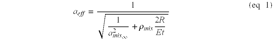
- FIG. 2 shows the effective propagation velocity, or effective system sound speed for a specific example of the
density meter 1 of FIG. 1 in accordance with the present invention. In this particular embodiment the effective system sound speed is shown for a fluid contained in a vacuum-backed, cylindrical steel conduit with acoustic propagation velocities and density representative of hydrocarbon liquid and water mixtures as typically found in the oil and gas industry. FIG. 2 shows the effect of varying the compliance of the pipe/fluid system by changing the wall thickness of a 5.50 inch OD steel pipe from some theoretical minimum value to a thickness of 0.5 inches for five different fluids having densities from 600 to 1000 kg/m3. As shown in FIG. 2, varying the thickness of the pipe has a significant effect on the effective speed of sound of the fluid/pipe system. For simplicity sake, the present invention is described with regard to particular embodiments comprising vacuum-backed conduits having sufficiently low frequencies (compared to breathing mode and resonant frequencies) that the pertinent dynamical response is captured by the static compliance of the conduit. The conduit may be vacuum backed by a concentric shell 15 (FIG. 1) or other suitable structure to isolate the sensing regions X1, X2 from the outside environment. In alternative embodiments the sensing regions X1, X2 may be isolated within theconcentric shell 15 by a known fluid or air. It is important that a static fluid having lower acoustic impedance than the fluid flowing within the pipe surround the sound speed meters. The advantages and effect of the vacuum backed conduit, as well as other isolation techniques, are described in commonly owned copending U.S. patent application Ser. No. 09/344,070, entitled “Measurement of Propagating Acoustic Waves in Compliant Pipes” incorporated herein by reference in its entirety. -
Equation 1 can be generalized in terms of the cross-sectional area compliance (σconduit) of the conduit and the infinite sound speed and density of the fluid and the effective sound speed of the pipe/fluid system as given by:
- The cross sectional area compliance is a measure of the increase in cross-sectional area of a conduit for a given increase in internal pressure as set forth in the following relationship:

- For a vacuum-backed, circular cross-section pipe of elastic modulus E, having an outside radius R, and wall thickness t, the conduit compliance is given by:

- It is important to note that, in general, the cross section area compliance of the fluid/pipe system can be a complex function of frequency and amplitude and can depend on all elements acoustically coupled to the conduit. For example, if an additional fluid surrounded the conduit, the acoustic properties of the surrounding fluid would influence the cross section area compliance presented to the compressional waves propagating internal to the conduit. It is for this reason that the present invention is presented in embodiments having a vacuum backed shell surrounding the sound speed meters as described herein above.
- In accordance with the present invention, using the relationships described herein above, the dependence of propagation speed of compression disturbances (one dimensional, planar compression acoustic waves) on the compliance of the
conduit 12 and fluid properties (such as namely sound speed and density) can be used to determine information regarding the fluid contained within the conduit, specifically, the density of the fluid. - Referring again to FIG. 1, there is shown a
density meter 1 in which the speed of sound of anunknown fluid 13 is measured within two regions X1, X2 wherein thepipe 12 has differing cross section area compliances associated with the two regions. A first effective speed of sound aeff1 of the fluid/pipe system is determined from an array of pressure measurements provided by sensors ofsound speed meter 14. A second speed of sound aeff2 of the fluid/pipe system is determined from an array of pressure measurements provided by sensors ofsound speed meter 16. As will be more fully described herein below, the change in propagation velocity of one dimensional acoustic waves between the two regions X1, X2, along with knowledge of the cross sectional compliances of each section, provides a means to determine the density of the fluid 13. As illustrated in this example, the variation in the system cross sectional compliance could be achieved through a change the conduit compliance, namely in the form of a change in wall thickness of the pipe. Other methods to vary the system cross sectional compliance are described below, and any known method of varying the system cross sectional compliance is contemplated by the present invention. - Embodiments of the present invention comprised of fiber optic based
sound speed meters - A plurality of the
density meters 1 of the present invention may be connected to a common cable and multiplexed together with other sound speed meters (not shown) using any known multiplexing technique. For instance, it is contemplated that the various embodiments of thedensity meter 1 of the present invention include the capability of being multiplexed as well as capable of communication with various protocols and systems currently in use in the industrial sensing area. For instance, and with reference to FIG. 1 there is shown a portion of a process control incorporating adensity meter 1 in accordance with the present invention with acontroller 58.Signal processing logic 60 communicates density signal ρx alongline 59 to controldevice 70, a computer or micro-processor for example, where the information may be used to control the fluid characteristics inpipe 12 through known controls means such as a pump, valve, throttle, etc. (not shown). In certain embodiments of the control system shown and with appropriate electro-optical conversion withinsignal processing logic 60 of the sensor return signal to a conventional 4-20 mA signal the signal can be combined with other control devices and sensors atcontrol device 58 via separate electrical lines. In this particular embodiment the communication from the fiber optic sensor is performed with a 4-20 mA analog signal, and the open protocol HART®. (Highway Addressable Remote Transducer) digital communications format. Similarly, communication from the fiberoptic density meter 1 may also be performed with open and interoperable protocol FOUNDATION™ Field bus that provides a digital communication link among intelligent field level and control devices via electrical lines. Thecontrol device 58 can be configured for use with other process protocols, including Device Bus, Sensor Bus, Profibus, the ethernet, and others in use throughout the world. The use of fiber optic based sound speed meters make thedensity meter 1 of the present invention uniquely qualified for industrial applications requiring multiple sensors. The use of multiplexed density meters through the use of feedthroughs (or other known techniques) in a large multi-point process enables connectivity to the multiple density meters through a single fiber optic cable. Electronic sensors of the prior art require dedicated wiring to the sensor and back to the instrumentation. For instance, a typical industrial process control system that utilizes electronic density meters of the prior art requires an electrical process loop to facilitate both a power signal to the transmitters and bi-directional communication, and can be constructed in accordance with a number of the aforementioned process communication protocols. - In operation, industrial process uses for the present invention include reverse osmosis, coking, general refining uses, in-line pressure sensors for emissions monitoring, sensors for monitoring hydrogen, combustion control, gas composition analysis, distributed sensors in tank gauging, multi-phase computational fluid dynamics, instrumentation of multiphase flows, among others.
- The invention will now be described with attention to another specific embodiment commonly found in the oil and gas industry with reference to FIGS. 1 and 3 wherein the system cross sectional compliance is varied by varying the fluid compliance. In this exemplary embodiment the
pipe 12 is comprised of a single material type, Inconel for example, have a wall thickness t1 at region X1 of 0.10 inches and a wall thickness of t2 at region X2 of 0.35 inches. The pipe is vacuum mandrel backed with ashell 15 isolating the sound speed meters from the outside environment. As best shown in FIG. 3 the change in sound speed for fluid mixtures, representative hydrocarbon and water mixtures, having densities ranging from 600 to 1000 kg/m3, is quite dramatic. As shown, the change in sound speed scales with the acoustic impedance of the fluid. For the least dense fluid with the slowest infinite medium sound speed (representing a light hydrocarbon), the change in wall thickness results in approximately 300 ft/sec change in sound speed. For the densest, highest infinite medium sound speed (representing, for example, a high watercut mixture), the change in wall thickness results in a 750 ft/sec change in sound speed. The expression for the change in effective speed of sound between two sections of vacuum-backed conduit differing only in wall thickness, where ao is the speed of sound of the fluid and ρo is the density of the fluid is given by:
- In accordance with the present invention, the density of the unknown fluid is determined by measuring two effective system sound speeds in two regions with differing, but known structural properties. For example, in the
cylindrical pipe 12 of FIG. 1 having a thickness t and elastic modulus E, the density ρmix of the unknown fluid is given by:
- As discussed herein above, varying wall thickness is but one way to achieve a change in system cross sectional area compliance and thereby provide a density measurement in accordance with the present invention. In general, the larger the change in system cross sectional area compliance between the two (or more regions) in which the sound speed is measured, the more robust the density measurement. In addition, an increase in the number of regions, i.e. greater than two, along a pipe with varying compliance in which system sound speeds are measured would give additional, redundant measurements of density. The additional data could yield a more robust or accurate overall system depending on the specific application.
- One alternative method to achieve large variations in system compliance by changing the conduit compliance is best shown with reference to FIG. 4 wherein a first sensing region in surrounding X 1 comprises a circular cross section conduit and second sensing region surrounding X2 comprises a non-circular cross section conduit, shown as an egg-shaped conduit by way of example, all other properties of the pipe remaining equal. The circular geometry surrounding X1 represents, for a given cross section, material modulus, and wall thickness, the configuration with the lowest cross sectional area compliance. However, the geometry of the cross section of the modified sensing region surrounding X2, such as by modifying or “egging” the circular section into an oval (or other alternative shapes such as using cross section possessing flattened sides) significantly increases the compliance of the
conduit 12. In certain embodiments between sensing region X2 (non-circular geometry) and sensing region X1 (circular geometry) of the same wall thickness t, cross sectional area compliance ratios greater than 30 are achievable. As demonstrated in the figures referenced herein above, increasing the compliance ratio of the pipe increases the sensitivity of thedensity meter 1 by increasing the system compliance ratio thereby increasing the change in effective system sound speed for a given fluid density. - The effective system cross sectional area compliance can be modified in a variety of manners such as, by way of example, varying materials, incorporating wall treatments, resonators or cavities. Referring to FIG. 5 there is shown a modified system cross sectional compliance technique wherein a closed cell foam 70 (or other compressible liner material) is positioned along the walls of one of the sensing sections of the
pipe 12 thereby modifying the effective compliance of that section of pipe. In the embodiment shown in FIG. 5, the pipe/fluid interface would be defined as the inner surface of the liner. An increase in fluid pressure would increase the effective cross sectional area of the fluid by both compressing the foam and by expanding the pipe. It is also contemplated by the present invention that the two sensing regions may be comprised of different material types or any other variation in geometry or material property that would effectuate a difference in the compliance of the pipe between the two sensing regions. - In another example of the present invention varying the compliance of the fluid or the area within the pipe can vary the system cross sectional compliance. For instance, referring to FIG. 6 additional system compliance could be introduced at a location along the pipe by positioning a
tube 72 within the flow path along one of the sensing regions. Thetube 72 would serve to modify the cross sectional compliance by compressing due to an increase in fluid pressure and would then combine with the compliance of the pipe to modify the effective sound speed of the fluid/pipe system. Other alternatives include embodiments wherein the tube is an air filled, sealed tube (or tubes) positioned within one sensing region of the pipe. - Referring again to FIG. 1 and defining α as the ratio of conduit compliance in the “soft” section, sensing region X 1, of the
density meter 1 to that of the “stiff” section, sensing region X2, of the meter, and where σ2 is the cross sectional area compliance of sensing region X2 of the meter, the density of the fluid ρmix within the meter can be expressed as:
- Referring now to FIG. 7 there is shown the speed of sound of a varying mixture of a two part brine/water fluid as measured in two sensing regions X 1, X2, of an embodiment of
density meter 1 of FIG. 1. The figure shows the various sound speeds versus oil volume fractions from 0% oil to 100% oil by volume. In the example shown the two sensing sections have a compliance ratio α of 10. As shown in FIG. 7 the difference in measured sound speed between the two sections varies from approximately 400 m/s for 100% brine, to approximately 200 m/s for 100% oil. As described herein above and depicted in the figure the effective system speed of sound as measured in the stiff section (X2) is significantly higher for the mixture than that measured in the less stiff section (X1) of thepipe 12. - In operation and referring again to FIG. 1, the two
sound speed meters processing logic 60, which includes the relationship set forth in equation 7. The compliance of the conduit σ2 in the second sensing region X2 and the ratio of the compliances between the two sections σ1/σ2 are further provided tologic 60 to calculate the density of the mixture ρmix. It is an important aspect of the present invention that the density of the fluid mixture can be determined without requiring specific speed of sound and calibration information on the fluid itself. In the embodiments described thus far it is only required that the sound speed and density of the fluid itself is the same in the two section. Thus, although the density measurement described herein is based on speed of sound measurements, no knowledge of the sound speed of the fluid is required to determine density. - In certain other embodiments the density of the fluid may be determined after the introduction of a known quantity of a known constituent into the fluid between the two sensing sections. Referring to FIG. 8 there is shown a
density meter 1 including aninput line 74 positioned between the two sensing sections X1, X2. In this particular embodiment the system cross sectional compliance is changed by the introduction of a constant amount of a known quantity of air 75, for example, into thefluid 13. The introduction of the air into the fluid changes the system cross-section compliance in the sensing region downstream ofinput line 74. The change in compliance in the fluid due to the introduction of the air is taken into account in the relationships described herein above to accurately determine the density of the fluid 13. - In addition to liquid mixtures, the density meter of the present invention includes the ability to determine the density of gas/liquid mixtures. Referring to FIG. 9 there is shown the predicted sound speeds in the stiff (X 2) and soft (X1) sensing regions of
density meter 1 depicted in FIG. 1 for various mixtures of gas and liquids with representative single phase compliances typical of produced gases and liquids at 100 bar. As shown, due primarily to the high compliance of the gas phase at this relatively low pressure, the change in overall sound speed in the two sections of the meter due to the change in conduit compliance is much less significant for this application than those described above. From Equation 2 and defining the compliance of the fluid as the inverse of the product of the fluid density and the square of the infinite dimensional sound speed yields the following relation:
- and the ratio of the effective sound speed within the conduit to the infinite dimensional sound speed is given by:

- The change in difference in sound speed for a given change in density of the fluid is a useful metric in designing the density meter described herein for any specific application. Assuming that the ratio of the cross sectional compliance introduced by the structure over that of the fluid is much less than 1, this performance metric can be expressed as follows:

- As shown, effectiveness of the density meter of the present invention described herein scales with both the ratio of the compliances of the two conduits as well as with the ratio of the compliance of conduit to that of the fluid. Thus, the density meter of the present invention is more effective when the system cross sectional compliance contributed by the conduit is a significant fraction of that contributed by the fluid and the ratio of the system cross sectional compliance of the two regions is significantly greater than one.
- It should be understood that any of the features, characteristics, alternatives or modifications described regarding a particular embodiment herein may also be applied, used, or incorporated with any other embodiment described herein.
- Although the invention has been described and illustrated with respect to exemplary embodiments thereof, the foregoing and various other additions and omissions may be made therein and thereto without departing from the spirit and scope of the present invention.
Claims (15)
Priority Applications (1)
| Application Number | Priority Date | Filing Date | Title |
|---|---|---|---|
| US10/011,605 US7059171B2 (en) | 2001-11-07 | 2001-11-09 | Fluid density measurement using acoustic pressures for industrial sensing applications |
Applications Claiming Priority (2)
| Application Number | Priority Date | Filing Date | Title |
|---|---|---|---|
| US10/010,183 US6971259B2 (en) | 2001-11-07 | 2001-11-07 | Fluid density measurement in pipes using acoustic pressures |
| US10/011,605 US7059171B2 (en) | 2001-11-07 | 2001-11-09 | Fluid density measurement using acoustic pressures for industrial sensing applications |
Related Parent Applications (1)
| Application Number | Title | Priority Date | Filing Date |
|---|---|---|---|
| US10/010,183 Continuation-In-Part US6971259B2 (en) | 2001-11-07 | 2001-11-07 | Fluid density measurement in pipes using acoustic pressures |
Publications (2)
| Publication Number | Publication Date |
|---|---|
| US20030089161A1 true US20030089161A1 (en) | 2003-05-15 |
| US7059171B2 US7059171B2 (en) | 2006-06-13 |
Family
ID=21744356
Family Applications (2)
| Application Number | Title | Priority Date | Filing Date |
|---|---|---|---|
| US10/010,183 Expired - Lifetime US6971259B2 (en) | 2001-11-07 | 2001-11-07 | Fluid density measurement in pipes using acoustic pressures |
| US10/011,605 Expired - Fee Related US7059171B2 (en) | 2001-11-07 | 2001-11-09 | Fluid density measurement using acoustic pressures for industrial sensing applications |
Family Applications Before (1)
| Application Number | Title | Priority Date | Filing Date |
|---|---|---|---|
| US10/010,183 Expired - Lifetime US6971259B2 (en) | 2001-11-07 | 2001-11-07 | Fluid density measurement in pipes using acoustic pressures |
Country Status (4)
| Country | Link |
|---|---|
| US (2) | US6971259B2 (en) |
| CA (1) | CA2461441C (en) |
| GB (1) | GB2395010B (en) |
| WO (1) | WO2003040718A1 (en) |
Cited By (48)
| Publication number | Priority date | Publication date | Assignee | Title |
|---|---|---|---|---|
| US20030154036A1 (en) * | 2002-01-23 | 2003-08-14 | Gysling Daniel L. | Apparatus and method for measuring parameters of a mixture having solid particles suspended in a fluid flowing in a pipe |
| US20040069069A1 (en) * | 2002-01-23 | 2004-04-15 | Gysling Daniel L. | Probe for measuring parameters of a flowing fluid and/or multiphase mixture |
| US20040074312A1 (en) * | 2002-08-08 | 2004-04-22 | Gysling Daniel L. | Apparatus and method for measuring multi-Phase flows in pulp and paper industry applications |
| US20040168522A1 (en) * | 2002-11-12 | 2004-09-02 | Fernald Mark R. | Apparatus having an array of clamp on piezoelectric film sensors for measuring parameters of a process flow within a pipe |
| US20040173010A1 (en) * | 2003-03-07 | 2004-09-09 | Gysling Daniel L. | Deployable mandrel for downhole measurements |
| US20040194539A1 (en) * | 2003-01-13 | 2004-10-07 | Gysling Daniel L. | Apparatus for measuring parameters of a flowing multiphase mixture |
| US20040199340A1 (en) * | 2003-01-13 | 2004-10-07 | Kersey Alan D. | Apparatus and method using an array of ultrasonic sensors for determining the velocity of a fluid within a pipe |
| US20040226386A1 (en) * | 2003-01-21 | 2004-11-18 | Gysling Daniel L. | Apparatus and method for measuring unsteady pressures within a large diameter pipe |
| US20050011283A1 (en) * | 2003-07-15 | 2005-01-20 | Gysling Daniel L. | Configurable multi-function flow measurement apparatus having an array of sensors |
| US20050011284A1 (en) * | 2003-07-15 | 2005-01-20 | Gysling Daniel L. | Dual function flow measurement apparatus having an array of sensors |
| US20050012935A1 (en) * | 2003-06-24 | 2005-01-20 | Kersey Alan D. | Characterizing unsteady pressures in pipes using optical measurement devices |
| WO2005012881A2 (en) * | 2003-08-01 | 2005-02-10 | Cidra Corporation | An apparatus and method for providing a density measurement augmented for entrained gas |
| US20050044929A1 (en) * | 2003-07-15 | 2005-03-03 | Gysling Daniel L. | Apparatus and method for compensating a coriolis meter |
| US20050061060A1 (en) * | 2003-07-15 | 2005-03-24 | Gysling Daniel L. | Apparatus and method for providing a density measurement augmented for entrained gas |
| US20050125170A1 (en) * | 2003-10-10 | 2005-06-09 | Gysling Daniel L. | Flow measurement apparatus having strain-based sensors and ultrasonic sensors |
| US20050125169A1 (en) * | 2003-11-25 | 2005-06-09 | Loose Douglas H. | Method and apparatus for measuring a parameter of a fluid flowing within a pipe using sub-array processing |
| US20050171710A1 (en) * | 2002-01-23 | 2005-08-04 | Cidra Corporation | Apparatus and method for measuring parameters of a mixture having solid particles suspended in a fluid flowing in a pipe |
| US20060037385A1 (en) * | 2004-05-17 | 2006-02-23 | Gysling Daniel L | Apparatus and method for measuring compositional parameters of a mixture |
| US20060096388A1 (en) * | 2004-11-05 | 2006-05-11 | Gysling Daniel L | System for measuring a parameter of an aerated multi-phase mixture flowing in a pipe |
| US7062976B2 (en) | 2003-01-21 | 2006-06-20 | Cidra Corporation | Apparatus and method of measuring gas volume fraction of a fluid flowing within a pipe |
| US20060155391A1 (en) * | 2005-01-10 | 2006-07-13 | Nokia Corporation | User input device |
| US7121152B2 (en) | 2003-06-06 | 2006-10-17 | Cidra Corporation | Portable flow measurement apparatus having an array of sensors |
| US7139667B2 (en) | 2002-11-22 | 2006-11-21 | Cidra Corporation | Method for calibrating a volumetric flow meter having an array of sensors |
| US20060260384A1 (en) * | 2002-01-23 | 2006-11-23 | Gysling Daniel L | Apparatus and method for measuring parameters of a mixture having liquid droplets suspended in a vapor flowing in a pipe |
| US20060266127A1 (en) * | 2005-05-27 | 2006-11-30 | Gysling Daniel L | Apparatus and method for fiscal measuring of an aerated fluid |
| US7146864B2 (en) | 2003-03-04 | 2006-12-12 | Cidra Corporation | Apparatus having a multi-band sensor assembly for measuring a parameter of a fluid flow flowing within a pipe |
| US7152003B2 (en) | 2003-12-11 | 2006-12-19 | Cidra Corporation | Method and apparatus for determining a quality metric of a measurement of a fluid parameter |
| US20070005272A1 (en) * | 2005-05-16 | 2007-01-04 | Gysling Daniel L | Method and apparatus for detecting and characterizing particles in a multiphase fluid |
| US20070006744A1 (en) * | 2005-07-07 | 2007-01-11 | Gysling Daniel L | Wet gas metering using a differential pressure based flow meter with a sonar based flow meter |
| US20070294039A1 (en) * | 2006-05-16 | 2007-12-20 | Cidra Corporation | Apparatus and method for determining a parameter in a wet gas flow |
| US7343818B2 (en) | 2003-01-21 | 2008-03-18 | Cidra Corporation | Apparatus and method of measuring gas volume fraction of a fluid flowing within a pipe |
| US20080098824A1 (en) * | 2006-11-01 | 2008-05-01 | Cidra Corporation | Apparatus And Method of Lensing An Ultrasonic Beam For An Ultrasonic Flow Meter |
| US20080098818A1 (en) * | 2006-10-30 | 2008-05-01 | Cidra Corporation | Apparatus and Method for Attenuating Acoustic Waves In Pipe Walls for Clamp-On Ultrasonic Flow Meter |
| US7367239B2 (en) | 2004-03-23 | 2008-05-06 | Cidra Corporation | Piezocable based sensor for measuring unsteady pressures inside a pipe |
| US7380438B2 (en) | 2004-09-16 | 2008-06-03 | Cidra Corporation | Apparatus and method for providing a fluid cut measurement of a multi-liquid mixture compensated for entrained gas |
| US7426852B1 (en) | 2004-04-26 | 2008-09-23 | Expro Meters, Inc. | Submersible meter for measuring a parameter of gas hold-up of a fluid |
| US20080236298A1 (en) * | 2005-07-07 | 2008-10-02 | Cidra Corporation | Wet Gas Metering Using A Differential Pressure And A Sonar Based Flow Meter |
| US20090013799A1 (en) * | 2003-07-15 | 2009-01-15 | Cidra Corporation | Apparatus And Method For Augmenting A Coriolis Meter |
| US7503227B2 (en) | 2005-07-13 | 2009-03-17 | Cidra Corporate Services, Inc | Method and apparatus for measuring parameters of a fluid flow using an array of sensors |
| WO2009040321A1 (en) * | 2007-09-20 | 2009-04-02 | Ge Inspection Technologies Gmbh | Method and system for ultrasonic inspection of workpieces |
| US20090097354A1 (en) * | 2007-10-16 | 2009-04-16 | Daniel Measurement And Control, Inc. | Method and System for Detecting Deposit Buildup Within an Ultrasonic Flow Meter |
| EP2080995A1 (en) * | 2007-12-05 | 2009-07-22 | Siemens Aktiengesellschaft | Magnetic-inductive flowmeter |
| US7624650B2 (en) | 2006-07-27 | 2009-12-01 | Expro Meters, Inc. | Apparatus and method for attenuating acoustic waves propagating within a pipe wall |
| US7672794B2 (en) | 2003-06-24 | 2010-03-02 | Expro Meters, Inc. | System and method for operating a flow process |
| US7752918B2 (en) | 2006-11-09 | 2010-07-13 | Expro Meters, Inc. | Apparatus and method for measuring a fluid flow parameter within an internal passage of an elongated body |
| CN102597741A (en) * | 2009-08-03 | 2012-07-18 | 乌尔蒂莫测量有限责任公司 | Method and apparatus for measurement of physical properties of free flowing materials in vessels |
| US9816848B2 (en) | 2014-01-23 | 2017-11-14 | Ultimo Measurement Llc | Method and apparatus for non-invasively measuring physical properties of materials in a conduit |
| US10113994B2 (en) | 2013-02-06 | 2018-10-30 | Ultimo Measurement Llc | Non-invasive method for measurement of physical properties of free flowing materials in vessels |
Families Citing this family (21)
| Publication number | Priority date | Publication date | Assignee | Title |
|---|---|---|---|---|
| GB2373058B (en) * | 2001-09-18 | 2003-02-19 | Tayside Flow Technologies Ltd | Spiral flow testing |
| US6986389B2 (en) * | 2003-05-02 | 2006-01-17 | Weatherford/Lamb, Inc. | Adjustable deployment apparatus for an actively clamped tubing-conveyed in-well seismic station |
| US7197938B2 (en) * | 2003-06-24 | 2007-04-03 | Cidra Corporation | Contact-based transducers for characterizing unsteady pressures in pipes |
| WO2005054789A1 (en) * | 2003-07-08 | 2005-06-16 | Cidra Corporation | Method and apparatus for measuring characteristics of core-annular flow |
| CA2537800C (en) * | 2003-08-08 | 2013-02-19 | Cidra Corporation | Piezocable based sensor for measuring unsteady pressures inside a pipe |
| US6910388B2 (en) * | 2003-08-22 | 2005-06-28 | Weatherford/Lamb, Inc. | Flow meter using an expanded tube section and sensitive differential pressure measurement |
| US20080264182A1 (en) * | 2003-08-22 | 2008-10-30 | Jones Richard T | Flow meter using sensitive differential pressure measurement |
| US7725270B2 (en) * | 2005-03-10 | 2010-05-25 | Expro Meters, Inc. | Industrial flow meter having an accessible digital interface |
| US7526966B2 (en) | 2005-05-27 | 2009-05-05 | Expro Meters, Inc. | Apparatus and method for measuring a parameter of a multiphase flow |
| US7263874B2 (en) * | 2005-06-08 | 2007-09-04 | Bioscale, Inc. | Methods and apparatus for determining properties of a fluid |
| US7516655B2 (en) * | 2006-03-30 | 2009-04-14 | Baker Hughes Incorporated | Downhole fluid characterization based on changes in acoustic properties with pressure |
| US8037747B2 (en) * | 2006-03-30 | 2011-10-18 | Baker Hughes Incorporated | Downhole fluid characterization based on changes in acoustic properties |
| US8131495B2 (en) * | 2008-08-19 | 2012-03-06 | Honeywell International Inc. | Particulate matter sensor calibration |
| GB2546937B (en) * | 2012-11-02 | 2017-11-29 | Silixa Ltd | Combining seismic survey and DAS fluid flow data for improved results |
| WO2016109451A1 (en) | 2014-12-29 | 2016-07-07 | Concentric Meter Corporation | Electromagnetic transducer |
| US10126266B2 (en) | 2014-12-29 | 2018-11-13 | Concentric Meter Corporation | Fluid parameter sensor and meter |
| EP3215812B1 (en) | 2014-12-29 | 2020-10-07 | Concentric Meter Corporation | Fluid parameter sensor and meter |
| US10316648B2 (en) | 2015-05-06 | 2019-06-11 | Baker Hughes Incorporated | Method of estimating multi-phase fluid properties in a wellbore utilizing acoustic resonance |
| CN110082253B (en) * | 2019-04-24 | 2021-10-01 | 北京工业大学 | Method for identifying fuel density on line according to pressure wave period |
| CN111189909A (en) * | 2020-01-09 | 2020-05-22 | 中国石油大学(北京) | Superficial layer water flow sound wave testing device |
| CN115792273B (en) * | 2022-11-02 | 2024-02-23 | 清华大学 | Method for measuring fluid flow rate, flow measuring device and computer storage medium |
Citations (3)
| Publication number | Priority date | Publication date | Assignee | Title |
|---|---|---|---|---|
| US5719329A (en) * | 1995-12-28 | 1998-02-17 | Ohio University | Ultrasonic measuring system and method of operation |
| US6502465B1 (en) * | 1999-09-27 | 2003-01-07 | Ohio University | Determining gas and liquid flow rates in a multi-phase flow |
| US6732575B2 (en) * | 1998-06-26 | 2004-05-11 | Cidra Corporation | Fluid parameter measurement for industrial sensing applications using acoustic pressures |
Family Cites Families (108)
| Publication number | Priority date | Publication date | Assignee | Title |
|---|---|---|---|---|
| US3149492A (en) * | 1961-03-06 | 1964-09-22 | Astra Inc | Fluid pressure gauge |
| US3851521A (en) * | 1973-01-19 | 1974-12-03 | M & J Valve Co | System and method for locating breaks in liquid pipelines |
| FR2357868A1 (en) | 1976-07-07 | 1978-02-03 | Schlumberger Compteurs | Vortex type fluid flow meter - uses differential pressure sensor outside pipe linked to two pressure valves inside pipe |
| DE2636737C2 (en) * | 1976-08-14 | 1978-06-22 | Danfoss A/S, Nordborg (Daenemark) | Device for the ultrasonic measurement of physical quantities of flowing media |
| US4080837A (en) * | 1976-12-03 | 1978-03-28 | Continental Oil Company | Sonic measurement of flow rate and water content of oil-water streams |
| DE2703439C3 (en) * | 1977-01-28 | 1979-08-09 | Danfoss A/S, Nordborg (Daenemark) | Device for measuring physical quantities of a liquid with two ultrasonic transducers |
| US4164865A (en) * | 1977-02-22 | 1979-08-21 | The Perkin-Elmer Corporation | Acoustical wave flowmeter |
| US4144768A (en) * | 1978-01-03 | 1979-03-20 | The Boeing Company | Apparatus for analyzing complex acoustic fields within a duct |
| JPS5543471A (en) * | 1978-09-25 | 1980-03-27 | Nissan Motor Co Ltd | Karman vortex flow meter |
| US4236406A (en) * | 1978-12-11 | 1980-12-02 | Conoco, Inc. | Method and apparatus for sonic velocity type water cut measurement |
| DE3172259D1 (en) * | 1980-11-21 | 1985-10-17 | Ici Plc | Method and apparatus for leak detection in pipelines |
| US4520320A (en) * | 1981-09-10 | 1985-05-28 | The United States Of America As Represented By The Secretary Of Commerce | Synchronous phase marker and amplitude detector |
| US4445389A (en) * | 1981-09-10 | 1984-05-01 | The United States Of America As Represented By The Secretary Of Commerce | Long wavelength acoustic flowmeter |
| US4499418A (en) * | 1982-08-05 | 1985-02-12 | Texaco Inc. | Water cut monitoring means and method |
| US4546649A (en) * | 1982-09-27 | 1985-10-15 | Kantor Frederick W | Instrumentation and control system and method for fluid transport and processing |
| US4515473A (en) * | 1984-09-13 | 1985-05-07 | Geo-Centers, Inc. | Photoelastic stress sensor signal processor |
| US4677305A (en) * | 1985-06-28 | 1987-06-30 | Simmonds Precision Products, Inc. | Opto-acoustic fuel quantity gauging system |
| CA1257712A (en) * | 1985-11-27 | 1989-07-18 | Toshimasa Tomoda | Metering choke |
| US4862750A (en) * | 1987-02-11 | 1989-09-05 | Nice Gerald J | Vortex shedding fluid velocity meter |
| JPH0423560Y2 (en) * | 1987-02-17 | 1992-06-02 | ||
| US4884457A (en) * | 1987-09-30 | 1989-12-05 | Texaco Inc. | Means and method for monitoring the flow of a multi-phase petroleum stream |
| US4864868A (en) * | 1987-12-04 | 1989-09-12 | Schlumberger Industries, Inc. | Vortex flowmeter transducer |
| NO166379C (en) * | 1987-12-18 | 1991-07-10 | Sensorteknikk As | PROCEDURE FOR REGISTERING MULTIPHASE FLOWS THROUGH A TRANSPORT SYSTEM. |
| US4813270A (en) * | 1988-03-04 | 1989-03-21 | Atlantic Richfield Company | System for measuring multiphase fluid flow |
| US4896540A (en) * | 1988-04-08 | 1990-01-30 | Parthasarathy Shakkottai | Aeroacoustic flowmeter |
| US5363342A (en) * | 1988-04-28 | 1994-11-08 | Litton Systems, Inc. | High performance extended fiber optic hydrophone |
| GB8817348D0 (en) * | 1988-07-21 | 1988-08-24 | Imperial College | Gas/liquid flow measurement |
| FR2637075B1 (en) * | 1988-09-23 | 1995-03-10 | Gaz De France | METHOD AND DEVICE FOR INDICATING THE FLOW OF A COMPRESSIBLE FLUID FLOWING IN A REGULATOR, AND VIBRATION SENSOR USED FOR THIS PURPOSE |
| US4950883A (en) * | 1988-12-27 | 1990-08-21 | United Technologies Corporation | Fiber optic sensor arrangement having reflective gratings responsive to particular wavelengths |
| JPH02203230A (en) * | 1989-01-31 | 1990-08-13 | Daikin Ind Ltd | Detector converter for variation in pressure in tube |
| US4947127A (en) * | 1989-02-23 | 1990-08-07 | Texaco Inc. | Microwave water cut monitor |
| US4932262A (en) * | 1989-06-26 | 1990-06-12 | General Motors Corporation | Miniature fiber optic pressure sensor |
| GB8918068D0 (en) * | 1989-08-08 | 1989-09-20 | Front Engineering Ltd | An apparatus for determining the time taken for sound to cross a body of fluid in an enclosure |
| US5024099A (en) * | 1989-11-20 | 1991-06-18 | Setra Systems, Inc. | Pressure transducer with flow-through measurement capability |
| US4996419A (en) | 1989-12-26 | 1991-02-26 | United Technologies Corporation | Distributed multiplexed optical fiber Bragg grating sensor arrangeement |
| US5317576A (en) * | 1989-12-26 | 1994-05-31 | United Technologies Corporation | Continously tunable single-mode rare-earth doped pumped laser arrangement |
| US5152181A (en) * | 1990-01-19 | 1992-10-06 | Lew Hyok S | Mass-volume vortex flowmeter |
| US5115670A (en) | 1990-03-09 | 1992-05-26 | Chevron Research & Technology Company | Measurement of fluid properties of two-phase fluids using an ultrasonic meter |
| US5099697A (en) * | 1990-04-02 | 1992-03-31 | Agar Corporation Ltd. | Two and three-phase flow measurement |
| US5040415A (en) | 1990-06-15 | 1991-08-20 | Rockwell International Corporation | Nonintrusive flow sensing system |
| FR2671877B1 (en) * | 1991-01-22 | 1993-12-03 | Centre Nal Recherc Scientifique | METHOD AND DEVICE FOR MEASURING INSTANT FLOW SPEED. |
| GB2280267B (en) | 1991-03-21 | 1995-05-24 | Halliburton Co | Device for sensing fluid behaviour |
| US5218197A (en) * | 1991-05-20 | 1993-06-08 | The United States Of America As Represented By The Secretary Of The Navy | Method and apparatus for the non-invasive measurement of pressure inside pipes using a fiber optic interferometer sensor |
| US5207107A (en) * | 1991-06-20 | 1993-05-04 | Exxon Research And Engineering Company | Non-intrusive flow meter for the liquid based on solid, liquid or gas borne sound |
| AU2433592A (en) | 1991-08-01 | 1993-03-02 | Micro Motion, Inc. | Coriolis effect mass flow meter |
| US5654551A (en) * | 1992-05-22 | 1997-08-05 | Commonwealth Scientific And Industrial Research Organisation | Method and apparatus for the measurement of the mass flow rates of fluid components in a multiphase slug flow |
| JPH0682281A (en) | 1992-09-01 | 1994-03-22 | Yokogawa Electric Corp | Vortex flowmeter |
| US5372046A (en) * | 1992-09-30 | 1994-12-13 | Rosemount Inc. | Vortex flowmeter electronics |
| TW295258U (en) | 1992-10-06 | 1997-01-01 | Caldon Inc | Apparatus for determining fluid flow |
| US5398542A (en) * | 1992-10-16 | 1995-03-21 | Nkk Corporation | Method for determining direction of travel of a wave front and apparatus therefor |
| US5361130A (en) | 1992-11-04 | 1994-11-01 | The United States Of America As Represented By The Secretary Of The Navy | Fiber grating-based sensing system with interferometric wavelength-shift detection |
| US5360331A (en) * | 1993-01-05 | 1994-11-01 | Dynisco, Inc. | Injection molding machine pressure transducer |
| US5513913A (en) * | 1993-01-29 | 1996-05-07 | United Technologies Corporation | Active multipoint fiber laser sensor |
| US5347873A (en) * | 1993-04-09 | 1994-09-20 | Badger Meter, Inc. | Double wing vortex flowmeter with strouhal number corrector |
| IT1262407B (en) * | 1993-09-06 | 1996-06-19 | Finmeccanica Spa | INSTRUMENTATION USING INTEGRATED OPTIC COMPONENTS FOR DIAGNOSTICS OF PARTS WITH FIBER OPTIC SENSORS INCLUDED OR FIXED ON THE SURFACE. |
| US5426297A (en) * | 1993-09-27 | 1995-06-20 | United Technologies Corporation | Multiplexed Bragg grating sensors |
| US5401956A (en) * | 1993-09-29 | 1995-03-28 | United Technologies Corporation | Diagnostic system for fiber grating sensors |
| US6003383A (en) * | 1994-03-23 | 1999-12-21 | Schlumberger Industries, S.A. | Vortex fluid meter incorporating a double obstacle |
| FR2720498B1 (en) | 1994-05-27 | 1996-08-09 | Schlumberger Services Petrol | Multiphase flowmeter. |
| US5842374A (en) | 1994-06-02 | 1998-12-01 | Changmin Co., Ltd. | Measuring method of a wide range level and an apparatus thereof |
| FR2721398B1 (en) * | 1994-06-21 | 1996-08-23 | Inst Francais Du Petrole | Method and device for monitoring, by periodic excitation, a flow of particles in a conduit. |
| US5597961A (en) * | 1994-06-27 | 1997-01-28 | Texaco, Inc. | Two and three phase flow metering with a water cut monitor and an orifice plate |
| GB9419006D0 (en) * | 1994-09-21 | 1994-11-09 | Sensor Dynamics Ltd | Apparatus for sensor installation |
| US5741980A (en) * | 1994-11-02 | 1998-04-21 | Foster-Miller, Inc. | Flow analysis system and method |
| AU710376B2 (en) * | 1995-02-09 | 1999-09-16 | Baker Hughes Incorporated | Computer controlled downhole tools for production well control |
| US5959547A (en) * | 1995-02-09 | 1999-09-28 | Baker Hughes Incorporated | Well control systems employing downhole network |
| US5730219A (en) * | 1995-02-09 | 1998-03-24 | Baker Hughes Incorporated | Production wells having permanent downhole formation evaluation sensors |
| US5732776A (en) * | 1995-02-09 | 1998-03-31 | Baker Hughes Incorporated | Downhole production well control system and method |
| US5706896A (en) * | 1995-02-09 | 1998-01-13 | Baker Hughes Incorporated | Method and apparatus for the remote control and monitoring of production wells |
| JP3803417B2 (en) * | 1995-04-11 | 2006-08-02 | テルモ カーディオバスキュラー システムズ コーポレイション | Combination of mounting pad and level sensor ultrasonic transducer and mounting mechanism for mounting the sensor on the wall |
| US5548530A (en) | 1995-04-24 | 1996-08-20 | Baumoel; Joseph | High-precision leak detector and locator |
| US5576497A (en) * | 1995-05-09 | 1996-11-19 | The Foxboro Company | Adaptive filtering for a vortex flowmeter |
| US5996690A (en) * | 1995-06-06 | 1999-12-07 | Baker Hughes Incorporated | Apparatus for controlling and monitoring a downhole oil/water separator |
| US5907104A (en) * | 1995-12-08 | 1999-05-25 | Direct Measurement Corporation | Signal processing and field proving methods and circuits for a coriolis mass flow meter |
| US5670720A (en) * | 1996-01-11 | 1997-09-23 | Morton International, Inc. | Wire-wrap low pressure sensor for pressurized gas inflators |
| CA2221152C (en) * | 1996-04-01 | 2004-03-16 | Baker Hughes Incorporated | Downhole flow control devices |
| US5642098A (en) | 1996-04-18 | 1997-06-24 | Oems Corporation | Capacitive oil water emulsion sensor system |
| IE76714B1 (en) * | 1996-04-19 | 1997-10-22 | Auro Environmental Ltd | Apparatus for measuring the velocity of a fluid flowing in a conduit |
| FR2748816B1 (en) * | 1996-05-17 | 1998-07-31 | Schlumberger Ind Sa | ULTRASONIC DEVICE FOR MEASURING THE FLOW SPEED OF A FLUID |
| FR2749080B1 (en) * | 1996-05-22 | 1998-08-07 | Schlumberger Services Petrol | METHOD AND APPARATUS FOR OPTICAL PHASE DISCRIMINATION FOR THREE-PHASE FLUID |
| US5708211A (en) * | 1996-05-28 | 1998-01-13 | Ohio University | Flow regime determination and flow measurement in multiphase flow pipelines |
| US5680489A (en) * | 1996-06-28 | 1997-10-21 | The United States Of America As Represented By The Secretary Of The Navy | Optical sensor system utilizing bragg grating sensors |
| US5939643A (en) * | 1996-08-21 | 1999-08-17 | Endress + Hauser Flowtec Ag | Vortex flow sensor with a cylindrical bluff body having roughned surface |
| US5835884A (en) * | 1996-10-04 | 1998-11-10 | Brown; Alvin E. | Method of determining a characteristic of a fluid |
| US5689540A (en) * | 1996-10-11 | 1997-11-18 | Schlumberger Technology Corporation | X-ray water fraction meter |
| US5842347A (en) * | 1996-10-25 | 1998-12-01 | Sengentrix, Inc. | Method and apparatus for monitoring the level of liquid nitrogen in a cryogenic storage tank |
| US5845033A (en) * | 1996-11-07 | 1998-12-01 | The Babcock & Wilcox Company | Fiber optic sensing system for monitoring restrictions in hydrocarbon production systems |
| GB9624899D0 (en) * | 1996-11-29 | 1997-01-15 | Schlumberger Ltd | Method and apparatus for measuring flow in a horizontal borehole |
| US5963880A (en) * | 1997-04-29 | 1999-10-05 | Schlumberger Industries, Inc. | Method for predicting water meter accuracy |
| US6002985A (en) * | 1997-05-06 | 1999-12-14 | Halliburton Energy Services, Inc. | Method of controlling development of an oil or gas reservoir |
| US5925879A (en) * | 1997-05-09 | 1999-07-20 | Cidra Corporation | Oil and gas well packer having fiber optic Bragg Grating sensors for downhole insitu inflation monitoring |
| DE19722274A1 (en) * | 1997-05-28 | 1998-12-03 | Degussa | Method for measuring density and mass flow |
| FR2764694B1 (en) * | 1997-06-17 | 1999-09-03 | Aerospatiale | DEVICE FOR MEASURING NOISE IN A CONDUIT BROUGHT BY A FLUID |
| US6016702A (en) * | 1997-09-08 | 2000-01-25 | Cidra Corporation | High sensitivity fiber optic pressure sensor for use in harsh environments |
| US5992519A (en) * | 1997-09-29 | 1999-11-30 | Schlumberger Technology Corporation | Real time monitoring and control of downhole reservoirs |
| US6371982B2 (en) * | 1997-10-09 | 2002-04-16 | St. Jude Medical Cardiovascular Group, Inc. | Graft structures with compliance gradients |
| US6009216A (en) * | 1997-11-05 | 1999-12-28 | Cidra Corporation | Coiled tubing sensor system for delivery of distributed multiplexed sensors |
| DE69924828T2 (en) * | 1998-01-16 | 2006-07-13 | Lattice Intellectual Property Ltd. | METHOD AND DEVICE FOR MEASURING THE COMBUSTION VALUE OF A GAS |
| US6227040B1 (en) * | 1998-02-03 | 2001-05-08 | Caldon, Inc. | Method and apparatus for determining the viscosity of a fluid in a container |
| US6354147B1 (en) | 1998-06-26 | 2002-03-12 | Cidra Corporation | Fluid parameter measurement in pipes using acoustic pressures |
| US6450037B1 (en) * | 1998-06-26 | 2002-09-17 | Cidra Corporation | Non-intrusive fiber optic pressure sensor for measuring unsteady pressures within a pipe |
| DE69927274T2 (en) * | 1998-06-26 | 2006-06-22 | Cidra Corp., Wallingford | NONINTRUSIVE FIBER OPTIC PRESSURE SENSOR FOR MEASURING PRESSURE CHANGES IN A TUBE |
| US6573548B2 (en) * | 1998-08-14 | 2003-06-03 | Monolithic System Technology, Inc. | DRAM cell having a capacitor structure fabricated partially in a cavity and method for operating same |
| US6158288A (en) * | 1999-01-28 | 2000-12-12 | Dolphin Technology, Inc. | Ultrasonic system for measuring flow rate, fluid velocity, and pipe diameter based upon time periods |
| US6233374B1 (en) | 1999-06-04 | 2001-05-15 | Cidra Corporation | Mandrel-wound fiber optic pressure sensor |
| US6435030B1 (en) * | 1999-06-25 | 2002-08-20 | Weatherford/Lamb, Inc. | Measurement of propagating acoustic waves in compliant pipes |
| US6279660B1 (en) * | 1999-08-05 | 2001-08-28 | Cidra Corporation | Apparatus for optimizing production of multi-phase fluid |
| US6349599B1 (en) * | 2000-05-02 | 2002-02-26 | Panametrics, Inc. | Layered ultrasonic coupler |
-
2001
- 2001-11-07 US US10/010,183 patent/US6971259B2/en not_active Expired - Lifetime
- 2001-11-09 US US10/011,605 patent/US7059171B2/en not_active Expired - Fee Related
-
2002
- 2002-11-05 WO PCT/GB2002/005004 patent/WO2003040718A1/en not_active Application Discontinuation
- 2002-11-05 CA CA002461441A patent/CA2461441C/en not_active Expired - Fee Related
- 2002-11-05 GB GB0403518A patent/GB2395010B/en not_active Expired - Fee Related
Patent Citations (4)
| Publication number | Priority date | Publication date | Assignee | Title |
|---|---|---|---|---|
| US5719329A (en) * | 1995-12-28 | 1998-02-17 | Ohio University | Ultrasonic measuring system and method of operation |
| US5719329B1 (en) * | 1995-12-28 | 1999-11-16 | Univ Ohio | Ultrasonic measuring system and method of operation |
| US6732575B2 (en) * | 1998-06-26 | 2004-05-11 | Cidra Corporation | Fluid parameter measurement for industrial sensing applications using acoustic pressures |
| US6502465B1 (en) * | 1999-09-27 | 2003-01-07 | Ohio University | Determining gas and liquid flow rates in a multi-phase flow |
Cited By (91)
| Publication number | Priority date | Publication date | Assignee | Title |
|---|---|---|---|---|
| US7337075B2 (en) | 2002-01-23 | 2008-02-26 | Cidra Corporation | Apparatus and method for measuring parameters of a mixture having liquid droplets suspended in a vapor flowing in a pipe |
| US20050171710A1 (en) * | 2002-01-23 | 2005-08-04 | Cidra Corporation | Apparatus and method for measuring parameters of a mixture having solid particles suspended in a fluid flowing in a pipe |
| US7275421B2 (en) | 2002-01-23 | 2007-10-02 | Cidra Corporation | Apparatus and method for measuring parameters of a mixture having solid particles suspended in a fluid flowing in a pipe |
| US7359803B2 (en) | 2002-01-23 | 2008-04-15 | Cidra Corporation | Apparatus and method for measuring parameters of a mixture having solid particles suspended in a fluid flowing in a pipe |
| US20060260384A1 (en) * | 2002-01-23 | 2006-11-23 | Gysling Daniel L | Apparatus and method for measuring parameters of a mixture having liquid droplets suspended in a vapor flowing in a pipe |
| US7328624B2 (en) | 2002-01-23 | 2008-02-12 | Cidra Corporation | Probe for measuring parameters of a flowing fluid and/or multiphase mixture |
| US20030154036A1 (en) * | 2002-01-23 | 2003-08-14 | Gysling Daniel L. | Apparatus and method for measuring parameters of a mixture having solid particles suspended in a fluid flowing in a pipe |
| US20040069069A1 (en) * | 2002-01-23 | 2004-04-15 | Gysling Daniel L. | Probe for measuring parameters of a flowing fluid and/or multiphase mixture |
| US20040074312A1 (en) * | 2002-08-08 | 2004-04-22 | Gysling Daniel L. | Apparatus and method for measuring multi-Phase flows in pulp and paper industry applications |
| US20040168522A1 (en) * | 2002-11-12 | 2004-09-02 | Fernald Mark R. | Apparatus having an array of clamp on piezoelectric film sensors for measuring parameters of a process flow within a pipe |
| US7400985B2 (en) | 2002-11-12 | 2008-07-15 | Cidra Corporation | Apparatus having an array of clamp on piezoelectric film sensors for measuring parameters of a process flow within a pipe |
| US7139667B2 (en) | 2002-11-22 | 2006-11-21 | Cidra Corporation | Method for calibrating a volumetric flow meter having an array of sensors |
| US7328113B2 (en) | 2002-11-22 | 2008-02-05 | Cidra Corporation | Method for calibrating a volumetric flow meter having an array of sensors |
| US20070067116A1 (en) * | 2002-11-22 | 2007-03-22 | Paul Rothman | Method for calibrating a volumetric flow meter having an array of sensors |
| US7096719B2 (en) | 2003-01-13 | 2006-08-29 | Cidra Corporation | Apparatus for measuring parameters of a flowing multiphase mixture |
| US20040199340A1 (en) * | 2003-01-13 | 2004-10-07 | Kersey Alan D. | Apparatus and method using an array of ultrasonic sensors for determining the velocity of a fluid within a pipe |
| US20040194539A1 (en) * | 2003-01-13 | 2004-10-07 | Gysling Daniel L. | Apparatus for measuring parameters of a flowing multiphase mixture |
| US7389187B2 (en) | 2003-01-13 | 2008-06-17 | Cidra Corporation | Apparatus and method using an array of ultrasonic sensors for determining the velocity of a fluid within a pipe |
| US20040226386A1 (en) * | 2003-01-21 | 2004-11-18 | Gysling Daniel L. | Apparatus and method for measuring unsteady pressures within a large diameter pipe |
| US7058549B2 (en) * | 2003-01-21 | 2006-06-06 | C1Dra Corporation | Apparatus and method for measuring unsteady pressures within a large diameter pipe |
| US7062976B2 (en) | 2003-01-21 | 2006-06-20 | Cidra Corporation | Apparatus and method of measuring gas volume fraction of a fluid flowing within a pipe |
| US7343818B2 (en) | 2003-01-21 | 2008-03-18 | Cidra Corporation | Apparatus and method of measuring gas volume fraction of a fluid flowing within a pipe |
| US7146864B2 (en) | 2003-03-04 | 2006-12-12 | Cidra Corporation | Apparatus having a multi-band sensor assembly for measuring a parameter of a fluid flow flowing within a pipe |
| US6986276B2 (en) * | 2003-03-07 | 2006-01-17 | Weatherford/Lamb, Inc. | Deployable mandrel for downhole measurements |
| US20040173010A1 (en) * | 2003-03-07 | 2004-09-09 | Gysling Daniel L. | Deployable mandrel for downhole measurements |
| US7302861B2 (en) | 2003-06-06 | 2007-12-04 | Cidra Corporation | Portable flow measurement apparatus having an array of sensors |
| US20070034017A1 (en) * | 2003-06-06 | 2007-02-15 | Winston Charles R | Portable flow measurement apparatus having an array of sensors |
| US7121152B2 (en) | 2003-06-06 | 2006-10-17 | Cidra Corporation | Portable flow measurement apparatus having an array of sensors |
| US7245385B2 (en) | 2003-06-24 | 2007-07-17 | Cidra Corporation | Characterizing unsteady pressures in pipes using optical measurement devices |
| US7672794B2 (en) | 2003-06-24 | 2010-03-02 | Expro Meters, Inc. | System and method for operating a flow process |
| US20050012935A1 (en) * | 2003-06-24 | 2005-01-20 | Kersey Alan D. | Characterizing unsteady pressures in pipes using optical measurement devices |
| US20050011283A1 (en) * | 2003-07-15 | 2005-01-20 | Gysling Daniel L. | Configurable multi-function flow measurement apparatus having an array of sensors |
| US20050061060A1 (en) * | 2003-07-15 | 2005-03-24 | Gysling Daniel L. | Apparatus and method for providing a density measurement augmented for entrained gas |
| US7134320B2 (en) | 2003-07-15 | 2006-11-14 | Cidra Corporation | Apparatus and method for providing a density measurement augmented for entrained gas |
| US7295933B2 (en) | 2003-07-15 | 2007-11-13 | Cidra Corporation | Configurable multi-function flow measurement apparatus having an array of sensors |
| US7596987B2 (en) | 2003-07-15 | 2009-10-06 | Expro Meters, Inc. | Apparatus and method for providing a density measurement augmented for entrained gas |
| US20090013799A1 (en) * | 2003-07-15 | 2009-01-15 | Cidra Corporation | Apparatus And Method For Augmenting A Coriolis Meter |
| US7793555B2 (en) | 2003-07-15 | 2010-09-14 | Expro Meters, Inc. | Apparatus and method for augmenting a coriolis meter |
| US7380439B2 (en) | 2003-07-15 | 2008-06-03 | Cidra Corporation | Apparatus and method for compensating a coriolis meter |
| US20080223129A1 (en) * | 2003-07-15 | 2008-09-18 | Gysling Daniel L | Apparatus and method for providing a density measurement augmented for entrained gas |
| US7340353B2 (en) | 2003-07-15 | 2008-03-04 | Cidra Corporation | Dual function flow measurement apparatus having an array of sensors |
| US20070125154A1 (en) * | 2003-07-15 | 2007-06-07 | Gysling Daniel L | Apparatus and method for compensating a coriolis meter |
| US20050044929A1 (en) * | 2003-07-15 | 2005-03-03 | Gysling Daniel L. | Apparatus and method for compensating a coriolis meter |
| US20050011284A1 (en) * | 2003-07-15 | 2005-01-20 | Gysling Daniel L. | Dual function flow measurement apparatus having an array of sensors |
| US7152460B2 (en) | 2003-07-15 | 2006-12-26 | Cidra Corporation | Apparatus and method for compensating a coriolis meter |
| US7127360B2 (en) | 2003-07-15 | 2006-10-24 | Cidra Corporation | Dual function flow measurement apparatus having an array of sensors |
| WO2005012881A3 (en) * | 2003-08-01 | 2005-05-06 | Cidra Corp | An apparatus and method for providing a density measurement augmented for entrained gas |
| WO2005012881A2 (en) * | 2003-08-01 | 2005-02-10 | Cidra Corporation | An apparatus and method for providing a density measurement augmented for entrained gas |
| US20050125170A1 (en) * | 2003-10-10 | 2005-06-09 | Gysling Daniel L. | Flow measurement apparatus having strain-based sensors and ultrasonic sensors |
| US20080022782A1 (en) * | 2003-10-10 | 2008-01-31 | Gysling Daniel L | Flow Measurement Apparatus Having Strain-Based Sensors and Ultrasonic Sensors |
| US7237440B2 (en) | 2003-10-10 | 2007-07-03 | Cidra Corporation | Flow measurement apparatus having strain-based sensors and ultrasonic sensors |
| US7430924B2 (en) | 2003-10-10 | 2008-10-07 | Expro Meters Inc. | Flow measurement apparatus having strain-based sensors and ultrasonic sensors |
| US7171315B2 (en) | 2003-11-25 | 2007-01-30 | Cidra Corporation | Method and apparatus for measuring a parameter of a fluid flowing within a pipe using sub-array processing |
| US20050125169A1 (en) * | 2003-11-25 | 2005-06-09 | Loose Douglas H. | Method and apparatus for measuring a parameter of a fluid flowing within a pipe using sub-array processing |
| US7379828B2 (en) | 2003-12-11 | 2008-05-27 | Cidra Corporation | Method and apparatus for determining a quality metric of a measurement of a fluid parameter |
| US7152003B2 (en) | 2003-12-11 | 2006-12-19 | Cidra Corporation | Method and apparatus for determining a quality metric of a measurement of a fluid parameter |
| US20070118304A1 (en) * | 2003-12-11 | 2007-05-24 | Loose Douglas H | Method and apparatus for determining a quality metric of a measurement of a fluid parameter |
| US7367239B2 (en) | 2004-03-23 | 2008-05-06 | Cidra Corporation | Piezocable based sensor for measuring unsteady pressures inside a pipe |
| US7426852B1 (en) | 2004-04-26 | 2008-09-23 | Expro Meters, Inc. | Submersible meter for measuring a parameter of gas hold-up of a fluid |
| US7363800B2 (en) | 2004-05-17 | 2008-04-29 | Cidra Corporation | Apparatus and method for measuring compositional parameters of a mixture |
| US20060037385A1 (en) * | 2004-05-17 | 2006-02-23 | Gysling Daniel L | Apparatus and method for measuring compositional parameters of a mixture |
| US7380438B2 (en) | 2004-09-16 | 2008-06-03 | Cidra Corporation | Apparatus and method for providing a fluid cut measurement of a multi-liquid mixture compensated for entrained gas |
| US7389687B2 (en) | 2004-11-05 | 2008-06-24 | Cidra Corporation | System for measuring a parameter of an aerated multi-phase mixture flowing in a pipe |
| US20060096388A1 (en) * | 2004-11-05 | 2006-05-11 | Gysling Daniel L | System for measuring a parameter of an aerated multi-phase mixture flowing in a pipe |
| US20060155391A1 (en) * | 2005-01-10 | 2006-07-13 | Nokia Corporation | User input device |
| US20070005272A1 (en) * | 2005-05-16 | 2007-01-04 | Gysling Daniel L | Method and apparatus for detecting and characterizing particles in a multiphase fluid |
| US7657392B2 (en) | 2005-05-16 | 2010-02-02 | Cidra Corporate Services, Inc. | Method and apparatus for detecting and characterizing particles in a multiphase fluid |
| US20060266127A1 (en) * | 2005-05-27 | 2006-11-30 | Gysling Daniel L | Apparatus and method for fiscal measuring of an aerated fluid |
| US7343820B2 (en) | 2005-05-27 | 2008-03-18 | Cidra Corporation | Apparatus and method for fiscal measuring of an aerated fluid |
| US7418877B2 (en) | 2005-07-07 | 2008-09-02 | Expro Meters, Inc. | Wet gas metering using a differential pressure based flow meter with a sonar based flow meter |
| US20070006727A1 (en) * | 2005-07-07 | 2007-01-11 | Gysling Daniel L | System and method for optimizing a gas/liquid separation process |
| US8641813B2 (en) | 2005-07-07 | 2014-02-04 | Expro Meters, Inc. | System and method for optimizing a gas/liquid separation process |
| US20080236298A1 (en) * | 2005-07-07 | 2008-10-02 | Cidra Corporation | Wet Gas Metering Using A Differential Pressure And A Sonar Based Flow Meter |
| US20070006744A1 (en) * | 2005-07-07 | 2007-01-11 | Gysling Daniel L | Wet gas metering using a differential pressure based flow meter with a sonar based flow meter |
| US7603916B2 (en) | 2005-07-07 | 2009-10-20 | Expro Meters, Inc. | Wet gas metering using a differential pressure and a sonar based flow meter |
| US7503227B2 (en) | 2005-07-13 | 2009-03-17 | Cidra Corporate Services, Inc | Method and apparatus for measuring parameters of a fluid flow using an array of sensors |
| US7454981B2 (en) | 2006-05-16 | 2008-11-25 | Expro Meters. Inc. | Apparatus and method for determining a parameter in a wet gas flow |
| US20070294039A1 (en) * | 2006-05-16 | 2007-12-20 | Cidra Corporation | Apparatus and method for determining a parameter in a wet gas flow |
| US7624650B2 (en) | 2006-07-27 | 2009-12-01 | Expro Meters, Inc. | Apparatus and method for attenuating acoustic waves propagating within a pipe wall |
| US20080098818A1 (en) * | 2006-10-30 | 2008-05-01 | Cidra Corporation | Apparatus and Method for Attenuating Acoustic Waves In Pipe Walls for Clamp-On Ultrasonic Flow Meter |
| US7624651B2 (en) | 2006-10-30 | 2009-12-01 | Expro Meters, Inc. | Apparatus and method for attenuating acoustic waves in pipe walls for clamp-on ultrasonic flow meter |
| US20080098824A1 (en) * | 2006-11-01 | 2008-05-01 | Cidra Corporation | Apparatus And Method of Lensing An Ultrasonic Beam For An Ultrasonic Flow Meter |
| US7673526B2 (en) | 2006-11-01 | 2010-03-09 | Expro Meters, Inc. | Apparatus and method of lensing an ultrasonic beam for an ultrasonic flow meter |
| US7752918B2 (en) | 2006-11-09 | 2010-07-13 | Expro Meters, Inc. | Apparatus and method for measuring a fluid flow parameter within an internal passage of an elongated body |
| WO2009040321A1 (en) * | 2007-09-20 | 2009-04-02 | Ge Inspection Technologies Gmbh | Method and system for ultrasonic inspection of workpieces |
| US20090097354A1 (en) * | 2007-10-16 | 2009-04-16 | Daniel Measurement And Control, Inc. | Method and System for Detecting Deposit Buildup Within an Ultrasonic Flow Meter |
| US8170812B2 (en) * | 2007-10-16 | 2012-05-01 | Daniel Measurement And Control, Inc. | Method and system for detecting deposit buildup within an ultrasonic flow meter |
| EP2080995A1 (en) * | 2007-12-05 | 2009-07-22 | Siemens Aktiengesellschaft | Magnetic-inductive flowmeter |
| CN102597741A (en) * | 2009-08-03 | 2012-07-18 | 乌尔蒂莫测量有限责任公司 | Method and apparatus for measurement of physical properties of free flowing materials in vessels |
| US10113994B2 (en) | 2013-02-06 | 2018-10-30 | Ultimo Measurement Llc | Non-invasive method for measurement of physical properties of free flowing materials in vessels |
| US9816848B2 (en) | 2014-01-23 | 2017-11-14 | Ultimo Measurement Llc | Method and apparatus for non-invasively measuring physical properties of materials in a conduit |
Also Published As
| Publication number | Publication date |
|---|---|
| US20030084707A1 (en) | 2003-05-08 |
| US6971259B2 (en) | 2005-12-06 |
| CA2461441A1 (en) | 2003-05-15 |
| GB2395010A (en) | 2004-05-12 |
| GB2395010B (en) | 2005-07-20 |
| US7059171B2 (en) | 2006-06-13 |
| CA2461441C (en) | 2008-07-15 |
| GB0403518D0 (en) | 2004-03-24 |
| WO2003040718A1 (en) | 2003-05-15 |
Similar Documents
| Publication | Publication Date | Title |
|---|---|---|
| US7059171B2 (en) | Fluid density measurement using acoustic pressures for industrial sensing applications | |
| US7059172B2 (en) | Phase flow measurement in pipes using a density meter | |
| US7322245B2 (en) | Apparatus and method for measuring a fluid flowing in a pipe using acoustic pressures | |
| EP1200806B1 (en) | Measurement of propagating acoustic waves in compliant pipes | |
| US7380438B2 (en) | Apparatus and method for providing a fluid cut measurement of a multi-liquid mixture compensated for entrained gas | |
| US7181955B2 (en) | Apparatus and method for measuring multi-Phase flows in pulp and paper industry applications | |
| US7526966B2 (en) | Apparatus and method for measuring a parameter of a multiphase flow | |
| EP1886098B1 (en) | An apparatus and method for measuring a parameter of a multiphase flow | |
| EP1751503B1 (en) | Apparatus and method for measuring the composition of a mixture flowing in a pipe | |
| US6354147B1 (en) | Fluid parameter measurement in pipes using acoustic pressures | |
| EP1982169B1 (en) | Apparatus and method for measuring parameters of a multiphase fluid flow | |
| RU2382989C9 (en) | Device for measurement of flow parametres | |
| WO2023028324A1 (en) | Methods and apparatus for determining the speed of sound within a piping network |
Legal Events
| Date | Code | Title | Description |
|---|---|---|---|
| AS | Assignment |
Owner name: CIDRA CORPORATION, CONNECTICUT Free format text: ASSIGNMENT OF ASSIGNORS INTEREST;ASSIGNOR:GYSLING, DANIEL L.;REEL/FRAME:012374/0024 Effective date: 20011109 |
|
| AS | Assignment |
Owner name: WEATHERFORD/LAMB, INC., TEXAS Free format text: ASSIGNMENT OF ASSIGNORS INTEREST;ASSIGNOR:CIDRA CORPORATION;REEL/FRAME:016502/0146 Effective date: 20050901 |
|
| FEPP | Fee payment procedure |
Free format text: PAYOR NUMBER ASSIGNED (ORIGINAL EVENT CODE: ASPN); ENTITY STATUS OF PATENT OWNER: LARGE ENTITY |
|
| FPAY | Fee payment |
Year of fee payment: 4 |
|
| FPAY | Fee payment |
Year of fee payment: 8 |
|
| AS | Assignment |
Owner name: WEATHERFORD TECHNOLOGY HOLDINGS, LLC, TEXAS Free format text: ASSIGNMENT OF ASSIGNORS INTEREST;ASSIGNOR:WEATHERFORD/LAMB, INC.;REEL/FRAME:034526/0272 Effective date: 20140901 |
|
| AS | Assignment |
Owner name: WEBSTER BANK, NATIONAL ASSOCIATION, CONNECTICUT Free format text: PATENT COLLATERAL ASSIGNMENT AND SECURITY AGREEMENT;ASSIGNOR:CIDRA CORPORATE SERVICES, INC.;REEL/FRAME:036818/0469 Effective date: 20150902 |
|
| AS | Assignment |
Owner name: CIDRA CORPORATE SERVICES, INC., CONNECTICUT Free format text: RELEASE AND REASSIGNMENT OF PATENTS;ASSIGNOR:WEBSTER BANK, NATIONAL ASSOCIATION;REEL/FRAME:044097/0723 Effective date: 20170929 |
|
| FEPP | Fee payment procedure |
Free format text: MAINTENANCE FEE REMINDER MAILED (ORIGINAL EVENT CODE: REM.) |
|
| LAPS | Lapse for failure to pay maintenance fees |
Free format text: PATENT EXPIRED FOR FAILURE TO PAY MAINTENANCE FEES (ORIGINAL EVENT CODE: EXP.) |
|
| STCH | Information on status: patent discontinuation |
Free format text: PATENT EXPIRED DUE TO NONPAYMENT OF MAINTENANCE FEES UNDER 37 CFR 1.362 |
|
| FP | Lapsed due to failure to pay maintenance fee |
Effective date: 20180613 |