US1854613A - Spraying device - Google Patents
Spraying device Download PDFInfo
- Publication number
- US1854613A US1854613A US565870A US56587031A US1854613A US 1854613 A US1854613 A US 1854613A US 565870 A US565870 A US 565870A US 56587031 A US56587031 A US 56587031A US 1854613 A US1854613 A US 1854613A
- Authority
- US
- United States
- Prior art keywords
- water
- pipe
- passages
- sprayer
- water container
- Prior art date
- Legal status (The legal status is an assumption and is not a legal conclusion. Google has not performed a legal analysis and makes no representation as to the accuracy of the status listed.)
- Expired - Lifetime
Links
Images
Classifications
-
- B—PERFORMING OPERATIONS; TRANSPORTING
- B05—SPRAYING OR ATOMISING IN GENERAL; APPLYING FLUENT MATERIALS TO SURFACES, IN GENERAL
- B05B—SPRAYING APPARATUS; ATOMISING APPARATUS; NOZZLES
- B05B3/00—Spraying or sprinkling apparatus with moving outlet elements or moving deflecting elements
-
- B—PERFORMING OPERATIONS; TRANSPORTING
- B05—SPRAYING OR ATOMISING IN GENERAL; APPLYING FLUENT MATERIALS TO SURFACES, IN GENERAL
- B05B—SPRAYING APPARATUS; ATOMISING APPARATUS; NOZZLES
- B05B17/00—Apparatus for spraying or atomising liquids or other fluent materials, not covered by the preceding groups
- B05B17/08—Fountains
Definitions
- This invention relates to improvements in spraying devices, and more particularly to Sprayers of the type used upon lawns, gardens, and the like.
- An object of the invention is to provide an attractive structure, and one which will effectively distribute the water on the lawn or flower bed.
- a further object of the invention is to provide a sprayer which has a fountain appearance, and a structure which is inexpensive to manufacture and durable and which is novel.
- a still further object of the invention is the provision of a sprayer which will not be uniform in its spraying but one which will distribute water merely by chance.
- a still further object of the invention is the provision of a free ball adapted to deflect the water as its leaves the nozzle, and means for retaining the ball in operative relation.
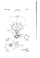
- Fig. 1 is a perspective view of the sprayer.
- Fig. 2 is a top plan view of the water container.
- 1 indicates a water container.
- the container is divided into subchambers 3 and 4 by means of a partition 5, curved about its center, as shown.
- a base 6 is supported by legs 7 pointed as shown, so as to more readily penetrate a short distance in the turf and hold the sprayer in position.
- the water container 1 is secured to the base by means of lugs 8 perforated as at 9 to receive bolts or screws 10.
- An intake pipe 11 communicates with subchamber-3.
- a similar pipe 12 communicates with the other subchamber 4:.
- a pipe 13 leads to a water supply under suitable head, such as the usual water supply of cities and towns, and communicates with both the pipes 11 and 12.
- a pipe 14 Leading upwardly from the water container 1 is another pipe 14., which communicates with a circularly arranged pipe 15 having small apertures 16. 17 is a central upstanding pipe which leads upwardly from the water container 1, and is open at its upper end.
- the pipe 15 is'supported by a number of ornamental wires 18, extendbut in the top surface of the pipe 15,'other holes are cut through on a true radius of the pipe, as at B. From this arrangement, the water, when it is turned on through the supply pipe 13 and pipes 11 and 12, will force-- fully emerge from the pipe 15 at different angles.
- 23 is a hollow ball, preferably of light material, such as celluloid or the like, which normally rests'in itsdotted position, as seen in Fig. 1. When, the wateris turned on, a jet, such as indicated in Fig. 1, results, which carries the ball into its full line position; the Water at the same time passing out through the apertures 16, as just indicated.
- the sprayer can be moved from place to place and remain in a ,stable position on account of the .pointed shape of the feet 7 and that the water is sprayed or distributed over a considerable radius.
- the course of the water, as it emerges from the holes A, is indicated by dotted lines 0 in Fig. 1.
- the course of the water as it emerges from the holes B is indicated in dotted lines D.
- a sprayer comprising a water container, having a partition to form two water passages, feed water pipes connecting the water passages to a source of supply, a vertically disposed pipe extending from and communicating with one of the water passages, an annular perforated pipe horizontally mounted above and spaced from the vertically disposed pipe by means of a pipe communicating with the other of the water passages and the annular perforated pipe, and valves for controlling the feed water pipes.
- a sprayer comprising a water container, having a partition to form two water passages, feed water pipes communicating with the passages, a hollow standard extend ing from the water container, a vertically disposed pipe communicating with one of the passages and extending above the hollow standard, an annular horizontal pipe above and spaced from the vertical pipe, said annular P p having wo set f p rf r tiens.
- Asprayer comprising a base provided with sharpened inclined legs, a water container, supported on the base, a hollow standard rising from the base and extending through the top of the water container, 2.
Description
Aprifi E9, 1932. s. ISHIKAWA SPRAYING DEVICE Fil-ed Sept. 29, 1951 INVENTOR. AS: ji/za aww A TTORNEYS.
Patented Apr. 19, 1932 UNITED STATES SADATOSHI ISHIKAWA, OF SEATTLE, WASHINGTON SPRAYING DEVICE Application filed September 29, 1931.. Serial No. 565,870.
This invention relates to improvements in spraying devices, and more particularly to Sprayers of the type used upon lawns, gardens, and the like.
An object of the invention is to provide an attractive structure, and one which will effectively distribute the water on the lawn or flower bed.
A further object of the invention is to provide a sprayer which has a fountain appearance, and a structure which is inexpensive to manufacture and durable and which is novel.
A still further object of the invention is the provision of a sprayer which will not be uniform in its spraying but one which will distribute water merely by chance.
A still further object of the invention is the provision of a free ball adapted to deflect the water as its leaves the nozzle, and means for retaining the ball in operative relation.
In the drawings:
Fig. 1 is a perspective view of the sprayer.
Fig. 2 is a top plan view of the water container.
Fig. 3 is a section taken on the line 3-3 of Fig. 1.
Referring now more particularly to the drawings, 1 indicates a water container. The container is divided into subchambers 3 and 4 by means of a partition 5, curved about its center, as shown. A base 6 is supported by legs 7 pointed as shown, so as to more readily penetrate a short distance in the turf and hold the sprayer in position. The water container 1 is secured to the base by means of lugs 8 perforated as at 9 to receive bolts or screws 10. An intake pipe 11 communicates with subchamber-3. A similar pipe 12 communicates with the other subchamber 4:. A pipe 13 leads to a water supply under suitable head, such as the usual water supply of cities and towns, and communicates with both the pipes 11 and 12. Leading upwardly from the water container 1 is another pipe 14., which communicates with a circularly arranged pipe 15 having small apertures 16. 17 is a central upstanding pipe which leads upwardly from the water container 1, and is open at its upper end. The pipe 15 is'supported by a number of ornamental wires 18, extendbut in the top surface of the pipe 15,'other holes are cut through on a true radius of the pipe, as at B. From this arrangement, the water, when it is turned on through the supply pipe 13 and pipes 11 and 12, will force-- fully emerge from the pipe 15 at different angles. 23 is a hollow ball, preferably of light material, such as celluloid or the like, which normally rests'in itsdotted position, as seen in Fig. 1. When, the wateris turned on, a jet, such as indicated in Fig. 1, results, which carries the ball into its full line position; the Water at the same time passing out through the apertures 16, as just indicated.
It is obvious that the sprayer can be moved from place to place and remain in a ,stable position on account of the .pointed shape of the feet 7 and that the water is sprayed or distributed over a considerable radius. The course of the water, as it emerges from the holes A, is indicated by dotted lines 0 in Fig. 1. The course of the water as it emerges from the holes B is indicated in dotted lines D.
While I have shown and described a particular form of embodiment of my invention, I am aware that many minor changes will readily suggest themselves to those skilled in the art without departing from the spirit and scope of my invention. I therefore desire to avoid being limited to the particular form of embodiment which I have hereinabove shown.
Having described my invention, What I claim as new is: p
1. A sprayer, comprising a water container, having a partition to form two water passages, feed water pipes connecting the water passages to a source of supply, a vertically disposed pipe extending from and communicating with one of the water passages, an annular perforated pipe horizontally mounted above and spaced from the vertically disposed pipe by means of a pipe communicating with the other of the water passages and the annular perforated pipe, and valves for controlling the feed water pipes.
2. A sprayer, comprising a water container, having a partition to form two water passages, feed water pipes communicating with the passages, a hollow standard extend ing from the water container, a vertically disposed pipe communicating with one of the passages and extending above the hollow standard, an annular horizontal pipe above and spaced from the vertical pipe, said annular P p having wo set f p rf r tiens.
angularly disposed to throw streams of water outwardly and vertically, supports extending from the standard to the annular pipe, and a pipe communicating with the other of the passages and the annular pipe.
, 3. Asprayer, comprising a base provided with sharpened inclined legs, a water container, supported on the base, a hollow standard rising from the base and extending through the top of the water container, 2.
a transverse partition in the water container,
Priority Applications (1)
| Application Number | Priority Date | Filing Date | Title |
|---|---|---|---|
| US565870A US1854613A (en) | 1931-09-29 | 1931-09-29 | Spraying device |
Applications Claiming Priority (1)
| Application Number | Priority Date | Filing Date | Title |
|---|---|---|---|
| US565870A US1854613A (en) | 1931-09-29 | 1931-09-29 | Spraying device |
Publications (1)
| Publication Number | Publication Date |
|---|---|
| US1854613A true US1854613A (en) | 1932-04-19 |
Family
ID=24260460
Family Applications (1)
| Application Number | Title | Priority Date | Filing Date |
|---|---|---|---|
| US565870A Expired - Lifetime US1854613A (en) | 1931-09-29 | 1931-09-29 | Spraying device |
Country Status (1)
| Country | Link |
|---|---|
| US (1) | US1854613A (en) |
Cited By (7)
| Publication number | Priority date | Publication date | Assignee | Title |
|---|---|---|---|---|
| US2785895A (en) * | 1953-11-23 | 1957-03-19 | Sr Aloys Neveling | Toy fountain |
| FR2403807A1 (en) * | 1977-09-23 | 1979-04-20 | Wham O Mfg Co | WATERPLAY TOY CONTAINING A PART OF A LIFTABLE HEADDRESS |
| US4496329A (en) * | 1983-04-29 | 1985-01-29 | Custom Concepts, Incorporated | Water jet toy |
| US4981622A (en) * | 1989-04-05 | 1991-01-01 | Nigrelli Systems, Inc. | Aeration apparatus and method |
| US6390391B1 (en) | 2001-08-03 | 2002-05-21 | Joyce Ulin | Sprinkler apparatus |
| US6848629B2 (en) | 2002-02-11 | 2005-02-01 | Stephen L. Palmer | Children's water toy |
| WO2022199860A1 (en) * | 2021-03-26 | 2022-09-29 | Schwatschke John | Water fountain with sphere |
-
1931
- 1931-09-29 US US565870A patent/US1854613A/en not_active Expired - Lifetime
Cited By (8)
| Publication number | Priority date | Publication date | Assignee | Title |
|---|---|---|---|---|
| US2785895A (en) * | 1953-11-23 | 1957-03-19 | Sr Aloys Neveling | Toy fountain |
| FR2403807A1 (en) * | 1977-09-23 | 1979-04-20 | Wham O Mfg Co | WATERPLAY TOY CONTAINING A PART OF A LIFTABLE HEADDRESS |
| US4205785A (en) * | 1977-09-23 | 1980-06-03 | Wham-O Mfg. Co. | Water play toy with elevatable crown portion |
| US4496329A (en) * | 1983-04-29 | 1985-01-29 | Custom Concepts, Incorporated | Water jet toy |
| US4981622A (en) * | 1989-04-05 | 1991-01-01 | Nigrelli Systems, Inc. | Aeration apparatus and method |
| US6390391B1 (en) | 2001-08-03 | 2002-05-21 | Joyce Ulin | Sprinkler apparatus |
| US6848629B2 (en) | 2002-02-11 | 2005-02-01 | Stephen L. Palmer | Children's water toy |
| WO2022199860A1 (en) * | 2021-03-26 | 2022-09-29 | Schwatschke John | Water fountain with sphere |
Similar Documents
| Publication | Publication Date | Title |
|---|---|---|
| US2943798A (en) | Variable spray pattern lawn sprinkler | |
| US1758767A (en) | Sprinkler | |
| US1854613A (en) | Spraying device | |
| US1577225A (en) | Rotary sprinkler | |
| US581252A (en) | William quayle | |
| US4156396A (en) | Root irrigation dripilator device with spray head | |
| US3633826A (en) | Lawn sprinkler | |
| US1989525A (en) | Lawn sprinkler | |
| US3820715A (en) | Ornamental rhythmic fountain | |
| KR100794607B1 (en) | Radial flow sprinkler | |
| US2859064A (en) | Rotary square lawn sprinkler | |
| US20080035766A1 (en) | Tree sprinkler | |
| US1651887A (en) | Sprinkler | |
| CN203737496U (en) | Fountain like rotary flower basket | |
| US1084094A (en) | Fountain spray-nozzle. | |
| US4852806A (en) | Spray structures for use in watering plants | |
| US2202349A (en) | Lawn sprinkler | |
| US671958A (en) | Lawn-sprinkler. | |
| US1349874A (en) | Lawn-sprinkling device | |
| US1746575A (en) | Rotary sprinkler | |
| US1741557A (en) | Lawn sprinkler | |
| US1702605A (en) | Lawn sprinkler | |
| CN203952220U (en) | Hand-force maneuvering self-propelled multifunctional sprayer | |
| JP3994250B2 (en) | Watering method | |
| CN113615547B (en) | Irrigation system for high-grade navel orange trees in high-mountain orchard |