EP2454994B1 - Portable X-ray machine with drive wheel suspension - Google Patents
Portable X-ray machine with drive wheel suspension Download PDFInfo
- Publication number
- EP2454994B1 EP2454994B1 EP11189442.4A EP11189442A EP2454994B1 EP 2454994 B1 EP2454994 B1 EP 2454994B1 EP 11189442 A EP11189442 A EP 11189442A EP 2454994 B1 EP2454994 B1 EP 2454994B1
- Authority
- EP
- European Patent Office
- Prior art keywords
- carriage frame
- wheel assembly
- rear wheel
- spring
- portable
- Prior art date
- Legal status (The legal status is an assumption and is not a legal conclusion. Google has not performed a legal analysis and makes no representation as to the accuracy of the status listed.)
- Not-in-force
Links
- 239000000725 suspension Substances 0.000 title claims description 43
- 238000003384 imaging method Methods 0.000 claims description 29
- 230000003247 decreasing effect Effects 0.000 claims description 5
- 230000007423 decrease Effects 0.000 claims description 4
- 230000008878 coupling Effects 0.000 claims 2
- 238000010168 coupling process Methods 0.000 claims 2
- 238000005859 coupling reaction Methods 0.000 claims 2
- 230000035939 shock Effects 0.000 description 8
- 230000006835 compression Effects 0.000 description 4
- 238000007906 compression Methods 0.000 description 4
- 239000000463 material Substances 0.000 description 3
- 244000043261 Hevea brasiliensis Species 0.000 description 2
- 230000006837 decompression Effects 0.000 description 2
- 229910052751 metal Inorganic materials 0.000 description 2
- 239000002184 metal Substances 0.000 description 2
- 229920003052 natural elastomer Polymers 0.000 description 2
- 229920001194 natural rubber Polymers 0.000 description 2
- 229920002379 silicone rubber Polymers 0.000 description 2
- 241000258920 Chilopoda Species 0.000 description 1
- VYZAMTAEIAYCRO-UHFFFAOYSA-N Chromium Chemical compound [Cr] VYZAMTAEIAYCRO-UHFFFAOYSA-N 0.000 description 1
- 235000004443 Ricinus communis Nutrition 0.000 description 1
- XUIMIQQOPSSXEZ-UHFFFAOYSA-N Silicon Chemical compound [Si] XUIMIQQOPSSXEZ-UHFFFAOYSA-N 0.000 description 1
- RTAQQCXQSZGOHL-UHFFFAOYSA-N Titanium Chemical compound [Ti] RTAQQCXQSZGOHL-UHFFFAOYSA-N 0.000 description 1
- 238000010521 absorption reaction Methods 0.000 description 1
- 238000010586 diagram Methods 0.000 description 1
- 230000005484 gravity Effects 0.000 description 1
- 230000002401 inhibitory effect Effects 0.000 description 1
- 238000009434 installation Methods 0.000 description 1
- 238000000034 method Methods 0.000 description 1
- 238000002601 radiography Methods 0.000 description 1
- 239000012858 resilient material Substances 0.000 description 1
- 229910052710 silicon Inorganic materials 0.000 description 1
- 239000010703 silicon Substances 0.000 description 1
- 229910001220 stainless steel Inorganic materials 0.000 description 1
- 239000010935 stainless steel Substances 0.000 description 1
- 239000010936 titanium Substances 0.000 description 1
- 229910052719 titanium Inorganic materials 0.000 description 1
Images


Classifications
-
- A—HUMAN NECESSITIES
- A61—MEDICAL OR VETERINARY SCIENCE; HYGIENE
- A61B—DIAGNOSIS; SURGERY; IDENTIFICATION
- A61B6/00—Apparatus for radiation diagnosis, e.g. combined with radiation therapy equipment
- A61B6/44—Constructional features of apparatus for radiation diagnosis
- A61B6/4405—Constructional features of apparatus for radiation diagnosis the apparatus being movable or portable, e.g. handheld or mounted on a trolley
-
- A—HUMAN NECESSITIES
- A61—MEDICAL OR VETERINARY SCIENCE; HYGIENE
- A61B—DIAGNOSIS; SURGERY; IDENTIFICATION
- A61B6/00—Apparatus for radiation diagnosis, e.g. combined with radiation therapy equipment
- A61B6/10—Application or adaptation of safety means
- A61B6/102—Protection against mechanical damage, e.g. anti-collision devices
-
- A—HUMAN NECESSITIES
- A61—MEDICAL OR VETERINARY SCIENCE; HYGIENE
- A61B—DIAGNOSIS; SURGERY; IDENTIFICATION
- A61B6/00—Apparatus for radiation diagnosis, e.g. combined with radiation therapy equipment
- A61B6/02—Devices for diagnosis sequentially in different planes; Stereoscopic radiation diagnosis
- A61B6/03—Computerised tomographs
- A61B6/032—Transmission computed tomography [CT]
- A61B6/035—Mechanical aspects of CT
Definitions
- the subject matter disclosed herein relates generally to a portable X-ray imaging system and more particularly to a drive wheel suspension system for the portable X-ray imaging system.
- US 2005/0179878 relates to an imaging apparatus that may be vehicle-mounted.
- US 2008/0008290 refers to an anatomical imaging system with a centipede belt drive.
- GB 794,937 describes a mobile radiography installation.
- a mobile radiographic imaging system such as a portable X-ray imaging system
- Mobile radiographic imaging systems may employ rigidly attached wheels positioned to allow an operator to move the imaging system from one location to another. With rigidly attached wheels, high shock loading may occur when the imaging system is pushed between locations due to the weight of the imaging system. Likewise, high shock loading may be accompanied by loud noises, and may cause vibrations and abnormally large, sudden loads on the system components, which can damage the drive trains and wheels, as well as circuit boards and other components.
- a portable X-ray imaging system according to the invention is defined in appended claim 1.
- a portable X-ray imaging system according to the preamble of claim 1 is known from US 3790805 A .
- Various aspects and embodiments of the present invention are defined by the appended claims.
- FIG. 1 depicts a portable X-ray system 10 in a transport position.
- the portable X-ray system 10 includes a base unit 12 with front wheels 14 and drive rear wheels 16.
- the wheels 14, 16 are mounted to the base unit 12 enabling the X-ray system 10 to be moved.
- An operator may move the X-ray system 10 by pushing on handles that may be located on the back end of the base unit 12 over the drive rear wheels 16.
- the operator may guide the system as it moves, but need not actually push the unit, which is instead propelled by drive motors associated with the wheeled support structure.
- the front wheels 14 are caster wheels which may swivel as the portable X-ray system 10 turns during transport.
- the front wheels 14 may be spring loaded castor wheels to provide front wheel suspension; such wheels are available commercially from Albion Incorporated of Albion, Michigan.
- the base unit 12 may include electronic circuitry and a power supply, such as one or more batteries.
- the power supply may provide power to operate the drive rear wheels 16.
- the power supply may drive one or more motors that may be attached to the rear wheels.
- a mast 18 is coupled to the base unit 12 and has a boom 20 extending outwardly, generally perpendicular to the mast 18.
- the mast 18 and/or the boom 20 may swivel on the base unit 12 to a position for radiographic exams to be performed, i.e., an imaging position.
- An X-ray source 22 is coupled to the boom 20 and enables the X-ray system 10 to produce X-rays needed to acquire image data during a radiographic exam. Cables may connect the X-ray source 22 to power and control circuitry located in the base unit 12.
- the base unit 12, mast 18, boom 20 and X-ray source 22 may create a heavy load on the wheels 14, 16. Therefore, the portable X-ray system 10, in accordance with the innovations described in this disclosure, may include a suspension system attached to the drive rear wheels 16 to reduce shock loading, vibration, and shaking that may occur when the system is being moved.
- FIG. 2 is an illustration depicting the portable X-ray system 10 of FIG. 1 in an imaging position 24.
- the mast 18 and/or the boom 20 is rotated 180 degrees from the transport position to cause the boom 20 to extend away from the X-ray system 10.
- the boom 20 and/or the X-ray source 22 may be adjusted toward or away from the mast 18 to properly position the X-ray source 22 over a patient.
- the center of gravity shifts away from the drive rear wheels 16 and toward the front wheels 14, thus decreasing the load on the drive rear wheels 16.
- the portable X-ray system 10 includes a suspension system attached to the drive rear wheels 16, the decreased load on the rear wheels 16 may force the suspension system against a stop, and thus provide a stable platform during imaging.
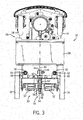
- FIG. 3 is an underside plan view of an embodiment of the portable X-ray system 10 of FIG. 1 with a suspension system.
- the front wheels 14 are mounted to a carriage frame 26 which includes a battery compartment 28.
- a rear wheel assembly 30 is mounted to the carriage frame 26 .
- the wheel assembly 30 includes the drive rear wheels 16 and motors 32.
- the motors 32 are coupled to the drive rear wheels 16 and may drive the rear wheels in rotation to propel the X-ray system 10.
- the battery compartment 28 may hold one or more batteries that provide power to the motors 32.
- a suspension assembly 34 provides suspension to the portable X-ray system 10.
- the rear wheel assembly 30 is attached to the carriage frame 26 at pivot points 36.
- the pivot points 36 aid in suspension by enabling the rear wheel assembly 30 to move flexibly in relation to the carriage frame 26.
- two pivot points 36 are illustrated, fewer or more pivot points may be used based on the configuration of the portable X-ray system 10. For example, if the width of an X-ray system increases, the number of pivot points may increase.
- the suspension assembly 34 includes a spring assembly 38 attached to a tang 40 extending out of the battery compartment 28.
- the spring assembly 38 includes a pivoting spring rod 42 with a clevis end 44.
- the tang 40 is secured inside the clevis end 44 of the pivoting spring rod 42 with a pin 46, thus connecting the suspension assembly 34 to the carriage frame 26.
- Such an attachment allows the tang 40 latitude to move within the clevis end 44 of the pivoting spring rod 42.
- Other embodiments may use different linking hardware to enable flexible movement between the rear wheel assembly 30 and the carriage frame 26.
- Pivot bushings 48 with bolts 50 extending through them secure the rear wheel assembly 30 to the carriage frame 26 and create the pivot points 36.
- the pivot bushings 48 may be made of natural rubber, silicon rubber, or another material that enables pivoting between the rear wheel assembly 30 and the carriage frame 26.
- the pivot bushings 48 may include a combination of rubber-like or resilient material and metal.
- the pivot bushings 48 may be fabricated center bonded mounts, available commercially from Lord Corporation of Cary, North Carolina.
- the suspension assembly 34 includes a spring 52 positioned around the pivoting spring rod 42 and moved toward the clevis end 44 of the rod 42 to expose a threaded end 54.
- a nut 56 securely tightened over the threaded end 54 secures the spring 52 in place.
- the spring 52 is oriented to extend generally in a direction parallel to a horizontal plane.
- the spring 52 is depicted as a compression spring, however, other springs such as belleville, volute, or cantilever springs may be used in other embodiments.
- the spring 52 may be composed of stainless steel, chrome silicon, titanium, or other suitable metal.
- the rear wheels may be independently or semi-independently suspended.
- multiple springs may be mounted on multiple pivoting spring rods with each spring rod attached to a tang, or certain embodiments may have springs mounted on each wheel so that each wheel independently provides suspension to the X-ray system 10.
- such arrangements may use differently configured suspension systems as well, and that described herein should be understood as one possible configuration.
- the load of the X-ray system 10 may force the carriage frame 26 downward. This downward load may cause the carriage frame 26 to press against the pivot points 36 and the clevis end 44 of the pivoting spring rod 42.
- the rear wheel assembly 30 may pivot at the pivot points 36 by compressing the material of the pivot bushings 48.
- the spring 52 may be compressed between the rear wheel assembly 30 and the nut 56 as the pivoting spring rod 42 is pulled toward the carriage frame 26. When this happens the tang 40 is enabled to pivot about the clevis end 44.
- the spring 52 may compress more. Conversely, as the load decreases, the spring 52 may become less compressed.
- the suspension assembly 34 may not compress the spring 52, but instead may cause the suspension system to rest in a normal position held against a stop.
- the suspension assembly 34 may operate in a similar manner when the X-ray system 10 travels over bumps or uneven surfaces.
- the uneven surfaces may produce high shock loading which causes the spring 52 of the suspension assembly 34 to compress and decompress back and forth for absorption of the shock. While the suspension assembly 34 absorbs the shock, noise and X-ray system 10 vibration may decrease.
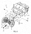
- FIG. 4 is an exploded perspective view of an embodiment of the portable X-ray system 10 of FIG. 3 depicting how the carriage frame 26, rear wheel assembly 30, and suspension assembly 34 are assembled.
- the carriage frame 26 includes apertures 58 on a structure extending perpendicular to the battery compartment 28, as illustrated.
- the apertures 58 are positioned on top of the pivot bushings 48.
- Bolts 50 are inserted through the pivot bushings 48 and the apertures 58, and secured with nuts to hold the carriage frame 26 to the rear wheel assembly 30.
- a cushion washer 60 is placed on the pivoting spring rod 42 near the clevis end 44 so that the cushion washer 60 rests against a portion of the rear wheel assembly 30 when assembled.
- the pivoting spring rod 42 is attached to the rear wheel assembly 30 by inserting it through the rear wheel assembly 30.
- the spring 52 slides over the pivoting spring rod 42 and the nut 56 secures the spring 52 in place.
- the pivoting spring rod 42 is connected to the carriage frame 26 by positioning the tang 40 within the clevis end 44 of the pivoting spring rod 42 and inserting the pin 46.
- the pin 46 holds the clevis end 44 of the rod 42 to the tang 40 via a nut secured to the end of the pin 46.
- the cushion washer 60 may enable the suspension assembly 34 to cushion the impact that may occur between the rear wheel assembly 30 and the pivoting spring rod 42 when the suspension assembly 34 moves against a stop, such as when the X-ray system 10 is moved from the transport position to the imaging position.
- the cushion washer 60 may be made of natural rubber, silicon rubber, or any other suitable material.
- the rear wheel assembly 30, the cushion washer 60, and the clevis end 44 of the pivoting spring rod 42 may operate as the stop for the suspension assembly 34.
- the rear wheel assembly 30 When operating as the stop, the rear wheel assembly 30 is pressed against the cushion washer 60 which is pressed against the clevis end 44 of the pivoting spring rod 42, thus inhibiting the spring 52 from further decompression.
- the stop inhibits movement of the carriage frame 26 with respect to the rear wheel assembly 30.
- the suspension assembly 34 may press the pivoting spring rod 42 against the stop when the load of the portable X-ray system 10 exerts sufficiently less force on the rear wheel assembly 30, such as when the X-ray system 10 is moved to an imaging position.
- FIG. 5 is an exploded side view of an embodiment of the portable X-ray system 10 of FIG. 4 depicting how the carriage frame 26, rear wheel assembly 30, and suspension assembly 34 are assembled.
- bolts 50 are inserted through the pivot bushings 48 and the apertures 58 while nuts attach to the bolts 50 to secure the carriage frame 26 to the rear wheel assembly 30.
- the cushion washer 60 is placed on the pivoting spring rod 42 near the clevis end 44 so that the cushion washer 60 rests against a lower extension 62 of the rear wheel assembly 30 when assembled.
- the pivoting spring rod 42 is attached to the rear wheel assembly 30 by inserting it through the lower extension 62.
- the spring 52 slides over the pivoting spring rod 42 and the nut 56 secures the spring 52 in place.
- the spring 52 is compressed between the nut 56 and the lower extension 62, and may be preloaded by appropriately locating the nut on the spring rod.
- the pivoting spring rod 42 is connected to the carriage frame 26 by positioning the tang 40 within the clevis end 44 of the pivoting spring rod 42 and inserting the pin 46.
- the pin 46 is held in place via a nut.
- the rear wheel assembly 30 may press downward at the pivot bushings 48.
- the rear wheel assembly 30 may pivot at the pivot bushings 48 and the pivoting spring rod 42 may be pulled toward the carriage frame 26 which results in the nut 56 compressing the spring 52 between itself and the lower extension 62.
- downward force may be removed from the pivot bushings 48.
- the suspension system may rest in a normal position where the spring 52 is decompressed as much as possible. In such a position, the lower extension 62 rests against the cushion washer 60, which acts as a stop (or it may be said that the lower extension 62 acts as a stop for the spring rod).
- the suspension system may operate in a similar manner when the rear wheel assembly 30 travels over bumps or uneven surfaces. For example, uneven surfaces may cause a quick shock that the suspension system absorbs through compression and decompression of the spring 52.
- FIG. 6 is a kinematic diagram depicting compression length changes (somewhat exaggerated) of the suspension system of FIG. 5 when the rear wheel assembly moves from a normal position 64 to a suspension position 66.
- the rear wheel assembly begins at the normal position 64, then as the assembly pivots and the spring compresses, the rear wheel assembly moves upward to a suspension position 66 (or it may be said that the base unit moves downwardly).
- Such an upward movement may occur as the portable X-ray system moves over bumps or objects in its path and the suspension system compresses its spring to compensate for these bumps.
- the spring has a spring length l , as indicated by reference numeral 68.
- the distance from the end of the spring to the stop is denoted as abutment-to-pin length L, as also indicated by reference numeral 70.
- the compressed spring has a shorter, compressed length l ', as indicated by reference numeral 72.
- the compressed abutment-to-pin length is then L', as indicated by reference numeral 74.
- the combined length of the spring length l and the abutment-to-pin length L will be equal to the combined length of compressed spring length l ' and the compressed abutment-to-pin length L'.
- FIG. 7 is a view depicting a moment 76 of the suspension system of FIG. 5 when the portable X-ray system is in the imaging position.
- a force 78 is exerted pressing the pivoting spring rod toward the lower extension of the rear wheel assembly, holding it firmly in place while imaging takes place.
- the suspension system is forced against the stop, thereby providing a stable position.
Description
- The subject matter disclosed herein relates generally to a portable X-ray imaging system and more particularly to a drive wheel suspension system for the portable X-ray imaging system.
-
US 2005/0179878 relates to an imaging apparatus that may be vehicle-mounted. -
US 2008/0008290 refers to an anatomical imaging system with a centipede belt drive. -
US 5,503,416 discusses an undercarriage for X-ray diagnostic equipment. -
GB 794,937 - In the hospital setting, mobile radiographic exams are performed on patients difficult to move or incapable of being moved. Also, in tertiary care medical centers, mobile radiographic exams represent a significant percentage of radiographic exams performed.
- To perform mobile radiographic exams, a mobile radiographic imaging system, such as a portable X-ray imaging system, may be used. Mobile radiographic imaging systems may employ rigidly attached wheels positioned to allow an operator to move the imaging system from one location to another. With rigidly attached wheels, high shock loading may occur when the imaging system is pushed between locations due to the weight of the imaging system. Likewise, high shock loading may be accompanied by loud noises, and may cause vibrations and abnormally large, sudden loads on the system components, which can damage the drive trains and wheels, as well as circuit boards and other components.
- Therefore, it may be desirable to reduce shock loading, which may result in quieter movement of the imaging system, improved operator comfort during movement, and decreased damage to the imaging system components. A portable X-ray imaging system according to the invention is defined in appended
claim 1. A portable X-ray imaging system according to the preamble ofclaim 1 is known fromUS 3790805 A . Various aspects and embodiments of the present invention are defined by the appended claims. - Various features, aspects, and advantages of the present invention will become better understood when the following detailed description is read with reference to the accompanying drawings in which like characters represent like parts throughout the drawings, wherein:
-
FIG. 1 is a perspective view of a portable X-ray system in a transport position; -
FIG. 2 is a perspective view of the portable X-ray system ofFIG. 1 in an imaging position; -
FIG. 3 is an underside plan view of an embodiment of the portable X-ray system ofFIG. 1 with a suspension system; -
FIG. 4 is an exploded perspective view of an embodiment of the portable X-ray system ofFIG. 3 ; -
FIG. 5 is an exploded side elevation view of an embodiment of the portable X-ray system ofFIG. 4 ; -
FIG. 6 is a diagrammatical view depicting compression length changes of the suspension system ofFIG. 5 when the rear wheel assembly moves from a normal position to a suspension position; and -
FIG. 7 is a diagrammatical view depicting a moment of the suspension system ofFIG. 5 when the portable X-ray system is in the imaging position. -
FIG. 1 depicts aportable X-ray system 10 in a transport position. Theportable X-ray system 10 includes abase unit 12 withfront wheels 14 and driverear wheels 16. Thewheels base unit 12 enabling theX-ray system 10 to be moved. An operator may move theX-ray system 10 by pushing on handles that may be located on the back end of thebase unit 12 over the driverear wheels 16. In certain designs, the operator may guide the system as it moves, but need not actually push the unit, which is instead propelled by drive motors associated with the wheeled support structure. In the illustrated embodiment, thefront wheels 14 are caster wheels which may swivel as theportable X-ray system 10 turns during transport. Furthermore, thefront wheels 14 may be spring loaded castor wheels to provide front wheel suspension; such wheels are available commercially from Albion Incorporated of Albion, Michigan. Thebase unit 12 may include electronic circuitry and a power supply, such as one or more batteries. The power supply may provide power to operate the driverear wheels 16. For example, the power supply may drive one or more motors that may be attached to the rear wheels. It may be noted that the batteries (or a separate power supply or power cable) may also serve to provide power for imaging sequences performed once the system is positioned at an imaging location (e.g., beside a bed or other patient support). - A
mast 18 is coupled to thebase unit 12 and has aboom 20 extending outwardly, generally perpendicular to themast 18. Themast 18 and/or theboom 20 may swivel on thebase unit 12 to a position for radiographic exams to be performed, i.e., an imaging position. AnX-ray source 22 is coupled to theboom 20 and enables theX-ray system 10 to produce X-rays needed to acquire image data during a radiographic exam. Cables may connect theX-ray source 22 to power and control circuitry located in thebase unit 12. As may be appreciated, thebase unit 12,mast 18,boom 20 andX-ray source 22 may create a heavy load on thewheels portable X-ray system 10, in accordance with the innovations described in this disclosure, may include a suspension system attached to the driverear wheels 16 to reduce shock loading, vibration, and shaking that may occur when the system is being moved. -
FIG. 2 is an illustration depicting theportable X-ray system 10 ofFIG. 1 in animaging position 24. In this position, as opposed to the transport position, themast 18 and/or theboom 20 is rotated 180 degrees from the transport position to cause theboom 20 to extend away from theX-ray system 10. Theboom 20 and/or theX-ray source 22 may be adjusted toward or away from themast 18 to properly position theX-ray source 22 over a patient. With theboom 20 and theX-ray source 22 extending away from thebase unit 12, the center of gravity shifts away from the driverear wheels 16 and toward thefront wheels 14, thus decreasing the load on the driverear wheels 16. As such, as described below, if theportable X-ray system 10 includes a suspension system attached to the driverear wheels 16, the decreased load on therear wheels 16 may force the suspension system against a stop, and thus provide a stable platform during imaging. -
FIG. 3 is an underside plan view of an embodiment of theportable X-ray system 10 ofFIG. 1 with a suspension system. Thefront wheels 14 are mounted to acarriage frame 26 which includes abattery compartment 28. Also mounted to thecarriage frame 26 is arear wheel assembly 30. Thewheel assembly 30 includes the driverear wheels 16 andmotors 32. Themotors 32 are coupled to the driverear wheels 16 and may drive the rear wheels in rotation to propel theX-ray system 10. Thebattery compartment 28 may hold one or more batteries that provide power to themotors 32. - A
suspension assembly 34 provides suspension to theportable X-ray system 10. Therear wheel assembly 30 is attached to thecarriage frame 26 atpivot points 36. The pivot points 36 aid in suspension by enabling therear wheel assembly 30 to move flexibly in relation to thecarriage frame 26. Although twopivot points 36 are illustrated, fewer or more pivot points may be used based on the configuration of theportable X-ray system 10. For example, if the width of an X-ray system increases, the number of pivot points may increase. - The
suspension assembly 34 includes aspring assembly 38 attached to atang 40 extending out of thebattery compartment 28. Thespring assembly 38 includes apivoting spring rod 42 with aclevis end 44. Thetang 40 is secured inside theclevis end 44 of the pivotingspring rod 42 with apin 46, thus connecting thesuspension assembly 34 to thecarriage frame 26. Such an attachment allows thetang 40 latitude to move within theclevis end 44 of the pivotingspring rod 42. Other embodiments may use different linking hardware to enable flexible movement between therear wheel assembly 30 and thecarriage frame 26. -
Pivot bushings 48 withbolts 50 extending through them secure therear wheel assembly 30 to thecarriage frame 26 and create thepivot points 36. Thepivot bushings 48 may be made of natural rubber, silicon rubber, or another material that enables pivoting between therear wheel assembly 30 and thecarriage frame 26. Alternatively, thepivot bushings 48 may include a combination of rubber-like or resilient material and metal. For example, thepivot bushings 48 may be fabricated center bonded mounts, available commercially from Lord Corporation of Cary, North Carolina. - In the illustrated embodiment, the
suspension assembly 34 includes aspring 52 positioned around the pivotingspring rod 42 and moved toward theclevis end 44 of therod 42 to expose a threadedend 54. Anut 56 securely tightened over the threadedend 54 secures thespring 52 in place. Thespring 52 is oriented to extend generally in a direction parallel to a horizontal plane. Thespring 52 is depicted as a compression spring, however, other springs such as belleville, volute, or cantilever springs may be used in other embodiments. Furthermore, thespring 52 may be composed of stainless steel, chrome silicon, titanium, or other suitable metal. - It should be noted that, while the present discussion describes a common or single suspension system for both rear wheels, in alternative configurations, the rear wheels may be independently or semi-independently suspended. For example, in other contemplated embodiments multiple springs may be mounted on multiple pivoting spring rods with each spring rod attached to a tang, or certain embodiments may have springs mounted on each wheel so that each wheel independently provides suspension to the
X-ray system 10. As with the illustrated embodiment, such arrangements may use differently configured suspension systems as well, and that described herein should be understood as one possible configuration. - In a transport position, the load of the
X-ray system 10 may force thecarriage frame 26 downward. This downward load may cause thecarriage frame 26 to press against the pivot points 36 and the clevis end 44 of the pivotingspring rod 42. Therear wheel assembly 30 may pivot at the pivot points 36 by compressing the material of thepivot bushings 48. In addition, thespring 52 may be compressed between therear wheel assembly 30 and thenut 56 as the pivotingspring rod 42 is pulled toward thecarriage frame 26. When this happens thetang 40 is enabled to pivot about theclevis end 44. As the load on thecarriage frame 26 increases, thespring 52 may compress more. Conversely, as the load decreases, thespring 52 may become less compressed. Furthermore, when the X-ray system is transitioned to the imaging position thesuspension assembly 34 may not compress thespring 52, but instead may cause the suspension system to rest in a normal position held against a stop. - The
suspension assembly 34 may operate in a similar manner when theX-ray system 10 travels over bumps or uneven surfaces. The uneven surfaces may produce high shock loading which causes thespring 52 of thesuspension assembly 34 to compress and decompress back and forth for absorption of the shock. While thesuspension assembly 34 absorbs the shock, noise andX-ray system 10 vibration may decrease. -
FIG. 4 is an exploded perspective view of an embodiment of theportable X-ray system 10 ofFIG. 3 depicting how thecarriage frame 26,rear wheel assembly 30, andsuspension assembly 34 are assembled. Thecarriage frame 26 includesapertures 58 on a structure extending perpendicular to thebattery compartment 28, as illustrated. To attach thecarriage frame 26 to therear wheel assembly 30, theapertures 58 are positioned on top of thepivot bushings 48.Bolts 50 are inserted through thepivot bushings 48 and theapertures 58, and secured with nuts to hold thecarriage frame 26 to therear wheel assembly 30. - A
cushion washer 60 is placed on the pivotingspring rod 42 near theclevis end 44 so that thecushion washer 60 rests against a portion of therear wheel assembly 30 when assembled. The pivotingspring rod 42 is attached to therear wheel assembly 30 by inserting it through therear wheel assembly 30. Thespring 52 slides over the pivotingspring rod 42 and thenut 56 secures thespring 52 in place. The pivotingspring rod 42 is connected to thecarriage frame 26 by positioning thetang 40 within the clevis end 44 of the pivotingspring rod 42 and inserting thepin 46. Thepin 46 holds theclevis end 44 of therod 42 to thetang 40 via a nut secured to the end of thepin 46. - The
cushion washer 60 may enable thesuspension assembly 34 to cushion the impact that may occur between therear wheel assembly 30 and the pivotingspring rod 42 when thesuspension assembly 34 moves against a stop, such as when theX-ray system 10 is moved from the transport position to the imaging position. Thecushion washer 60 may be made of natural rubber, silicon rubber, or any other suitable material. - Combined together, the
rear wheel assembly 30, thecushion washer 60, and the clevis end 44 of the pivotingspring rod 42 may operate as the stop for thesuspension assembly 34. When operating as the stop, therear wheel assembly 30 is pressed against thecushion washer 60 which is pressed against the clevis end 44 of the pivotingspring rod 42, thus inhibiting thespring 52 from further decompression. The stop inhibits movement of thecarriage frame 26 with respect to therear wheel assembly 30. Furthermore, thesuspension assembly 34 may press the pivotingspring rod 42 against the stop when the load of theportable X-ray system 10 exerts sufficiently less force on therear wheel assembly 30, such as when theX-ray system 10 is moved to an imaging position. -
FIG. 5 is an exploded side view of an embodiment of theportable X-ray system 10 ofFIG. 4 depicting how thecarriage frame 26,rear wheel assembly 30, andsuspension assembly 34 are assembled. As previously described in relation toFIG. 4 ,bolts 50 are inserted through thepivot bushings 48 and theapertures 58 while nuts attach to thebolts 50 to secure thecarriage frame 26 to therear wheel assembly 30. - The
cushion washer 60 is placed on the pivotingspring rod 42 near theclevis end 44 so that thecushion washer 60 rests against alower extension 62 of therear wheel assembly 30 when assembled. The pivotingspring rod 42 is attached to therear wheel assembly 30 by inserting it through thelower extension 62. Thespring 52 slides over the pivotingspring rod 42 and thenut 56 secures thespring 52 in place. Thus, thespring 52 is compressed between thenut 56 and thelower extension 62, and may be preloaded by appropriately locating the nut on the spring rod. Again, the pivotingspring rod 42 is connected to thecarriage frame 26 by positioning thetang 40 within the clevis end 44 of the pivotingspring rod 42 and inserting thepin 46. Thepin 46 is held in place via a nut. - As the load on the
carriage frame 26 increases, therear wheel assembly 30 may press downward at thepivot bushings 48. Therear wheel assembly 30 may pivot at thepivot bushings 48 and the pivotingspring rod 42 may be pulled toward thecarriage frame 26 which results in thenut 56 compressing thespring 52 between itself and thelower extension 62. Conversely, when the load on thecarriage frame 26 decreases, downward force may be removed from thepivot bushings 48. When enough weight is removed, the suspension system may rest in a normal position where thespring 52 is decompressed as much as possible. In such a position, thelower extension 62 rests against thecushion washer 60, which acts as a stop (or it may be said that thelower extension 62 acts as a stop for the spring rod).. The suspension system may operate in a similar manner when therear wheel assembly 30 travels over bumps or uneven surfaces. For example, uneven surfaces may cause a quick shock that the suspension system absorbs through compression and decompression of thespring 52. -
FIG. 6 is a kinematic diagram depicting compression length changes (somewhat exaggerated) of the suspension system ofFIG. 5 when the rear wheel assembly moves from a normal position 64 to asuspension position 66. The rear wheel assembly begins at the normal position 64, then as the assembly pivots and the spring compresses, the rear wheel assembly moves upward to a suspension position 66 (or it may be said that the base unit moves downwardly). Such an upward movement may occur as the portable X-ray system moves over bumps or objects in its path and the suspension system compresses its spring to compensate for these bumps. - As illustrated, in the
normal position 66, the spring has a spring length l, as indicated byreference numeral 68. The distance from the end of the spring to the stop is denoted as abutment-to-pin length L, as also indicated byreference numeral 70. Alternatively, in thesuspension position 66 the compressed spring has a shorter, compressed length l', as indicated byreference numeral 72. The compressed abutment-to-pin length is then L', as indicated byreference numeral 74. As may be appreciated, the combined length of the spring length l and the abutment-to-pin length L will be equal to the combined length of compressed spring length l' and the compressed abutment-to-pin length L'. -
FIG. 7 is a view depicting amoment 76 of the suspension system ofFIG. 5 when the portable X-ray system is in the imaging position. With themoment 76, aforce 78 is exerted pressing the pivoting spring rod toward the lower extension of the rear wheel assembly, holding it firmly in place while imaging takes place. In other words, the suspension system is forced against the stop, thereby providing a stable position. - This written description uses examples to disclose the invention, including the preferred mode, and also to enable any person skilled in the art to practice the invention, including making and using any devices or systems and performing any incorporated methods. The patentable scope of the invention is defined by the claims, and may include other examples that occur to those skilled in the art.
Claims (2)
- A portable X-ray imaging system (10), comprising:a base unit (12) having a carriage frame (26), wherein the base unit (12) supports an X-ray source (22), and wherein the X-ray source (22) is moveable between a transport position and an imaging position;at least one front wheel (14) mounted to the carriage frame (26);a rear wheel assembly (30) mounted to the carriage frame (26), the rear wheel assembly (30) comprising a pair of rear wheels (16) and at least one battery driven drive motor (32) for driving the rear wheels (16) in rotation to propel the base unit (12);a pivot coupling between the carriage frame (26) and the rear wheel assembly (30); anda suspension system (34) coupled to the carriage frame (26) and the rear wheel assembly (30) and configured to permit flexible movement of the carriage frame (26) and the rear wheel assembly (30) with respect to one another; characterised in that the X-ray source (22) being in the imaging position causes a decreased load to be exerted on the carriage frame (26) compared to the X-ray source (22) being in the transport position;the pivot coupling is configured to yield to relative movement of the carriage frame (26) and the rear wheel assembly (30) when the load on the carriage frame (26) decreases or increases;the suspension system (34) comprises a spring (52) arranged to be transitioned, by the relative movement of the carriage frame (26) and the rear wheel assembly (30), between a relatively uncompressed state when there is a decreased load on the carriage frame (26) and a relatively compressed state when there is an increased load on the carriage frame (26); andin its uncompressed state, the spring (52) rests against a stop thereby limiting movement of the carriage frame (26) with respect to the rear wheel assembly (30).
- The system (10) of claim 1, comprising at least one cushion element configured to cushion impact when movement of the carriage frame (26) with respect to the rear wheel assembly (30) is limited via the stop.
Applications Claiming Priority (1)
| Application Number | Priority Date | Filing Date | Title |
|---|---|---|---|
| US12/953,218 US8459868B2 (en) | 2010-11-23 | 2010-11-23 | Portable X-ray machine with drive wheel suspension |
Publications (2)
| Publication Number | Publication Date |
|---|---|
| EP2454994A1 EP2454994A1 (en) | 2012-05-23 |
| EP2454994B1 true EP2454994B1 (en) | 2017-10-04 |
Family
ID=45033813
Family Applications (1)
| Application Number | Title | Priority Date | Filing Date |
|---|---|---|---|
| EP11189442.4A Not-in-force EP2454994B1 (en) | 2010-11-23 | 2011-11-16 | Portable X-ray machine with drive wheel suspension |
Country Status (4)
| Country | Link |
|---|---|
| US (1) | US8459868B2 (en) |
| EP (1) | EP2454994B1 (en) |
| JP (1) | JP5897879B2 (en) |
| CN (1) | CN102551770B (en) |
Families Citing this family (10)
| Publication number | Priority date | Publication date | Assignee | Title |
|---|---|---|---|---|
| JP6242060B2 (en) | 2013-02-19 | 2017-12-06 | キヤノン株式会社 | Mobile X-ray equipment |
| US10151710B2 (en) * | 2014-07-18 | 2018-12-11 | Peltec Services, Inc. | Portable industrial radiography apparatus |
| JP6145899B2 (en) * | 2015-07-16 | 2017-06-14 | 富士フイルム株式会社 | Radiation imaging equipment |
| CN105708486A (en) * | 2016-03-19 | 2016-06-29 | 秦存凤 | Movable radiological CT (Computed Tomography) device |
| CN106585700B (en) * | 2016-12-09 | 2019-07-16 | 中央军委后勤保障部卫生局药品仪器检验所 | Wheel system and Portable digital X-ray apparatus |
| WO2018142557A1 (en) * | 2017-02-03 | 2018-08-09 | 株式会社島津製作所 | Portable radiation imaging apparatus |
| CN108621700B (en) * | 2017-03-20 | 2023-11-28 | 通用电气公司 | Medical device |
| USD860458S1 (en) * | 2017-09-27 | 2019-09-17 | Fujifilm Corporation | Medical X-ray imaging apparatus |
| US11399784B2 (en) | 2017-09-29 | 2022-08-02 | Medtronic Navigation, Inc. | System and method for mobile imaging |
| US11690582B2 (en) * | 2020-05-06 | 2023-07-04 | GE Precision Healthcare LLC | Systems and methods for a mobile medical device drive platform |
Citations (3)
| Publication number | Priority date | Publication date | Assignee | Title |
|---|---|---|---|---|
| US3790805A (en) * | 1971-04-19 | 1974-02-05 | Picker Corp | Mobile x-ray unit |
| US4887287A (en) * | 1988-05-06 | 1989-12-12 | U.S. Philips Corporation | Mobile x-ray apparatus comprising exchangeable wheels |
| US6814490B1 (en) * | 2000-01-14 | 2004-11-09 | Ao-Entwicklungsinstitut Davos | Device for moving a medical apparatus in a controlled manner |
Family Cites Families (9)
| Publication number | Priority date | Publication date | Assignee | Title |
|---|---|---|---|---|
| GB794937A (en) | 1955-05-03 | 1958-05-14 | Haran Ets | Mobile radiography installation |
| JPH0349688Y2 (en) * | 1985-11-14 | 1991-10-23 | ||
| US5503416A (en) | 1994-03-10 | 1996-04-02 | Oec Medical Systems, Inc. | Undercarriage for X-ray diagnostic equipment |
| US6823037B2 (en) | 2001-04-05 | 2004-11-23 | Analogic Corporation | Roller truck for CT scanner |
| JP2005227717A (en) * | 2004-02-16 | 2005-08-25 | Fuji Photo Film Co Ltd | Fixing structure for image forming apparatus |
| US7175347B2 (en) * | 2004-07-30 | 2007-02-13 | Neurologica, Corp. | Anatomical imaging system with centipede belt drive |
| JP4612832B2 (en) * | 2004-12-03 | 2011-01-12 | キヤノン株式会社 | Radiation imaging apparatus and control method thereof |
| CN201019953Y (en) * | 2006-10-12 | 2008-02-13 | 高斌 | Electric medical treatment transfer cart |
| KR101778819B1 (en) | 2009-12-18 | 2017-09-14 | 제너럴 일렉트릭 캄파니 | System and method to automatically assist mobile image acquisition |
-
2010
- 2010-11-23 US US12/953,218 patent/US8459868B2/en active Active
-
2011
- 2011-11-16 EP EP11189442.4A patent/EP2454994B1/en not_active Not-in-force
- 2011-11-18 JP JP2011252267A patent/JP5897879B2/en not_active Expired - Fee Related
- 2011-11-23 CN CN201110461909.3A patent/CN102551770B/en active Active
Patent Citations (3)
| Publication number | Priority date | Publication date | Assignee | Title |
|---|---|---|---|---|
| US3790805A (en) * | 1971-04-19 | 1974-02-05 | Picker Corp | Mobile x-ray unit |
| US4887287A (en) * | 1988-05-06 | 1989-12-12 | U.S. Philips Corporation | Mobile x-ray apparatus comprising exchangeable wheels |
| US6814490B1 (en) * | 2000-01-14 | 2004-11-09 | Ao-Entwicklungsinstitut Davos | Device for moving a medical apparatus in a controlled manner |
Also Published As
| Publication number | Publication date |
|---|---|
| CN102551770A (en) | 2012-07-11 |
| US8459868B2 (en) | 2013-06-11 |
| EP2454994A1 (en) | 2012-05-23 |
| US20120128130A1 (en) | 2012-05-24 |
| JP2012110702A (en) | 2012-06-14 |
| JP5897879B2 (en) | 2016-04-06 |
| CN102551770B (en) | 2016-01-27 |
Similar Documents
| Publication | Publication Date | Title |
|---|---|---|
| EP2454994B1 (en) | Portable X-ray machine with drive wheel suspension | |
| US5425069A (en) | Mobile X-ray apparatus | |
| US8753009B2 (en) | Drive system for imaging device | |
| US11925494B2 (en) | System and method for mobile imaging | |
| US8960340B2 (en) | Power add-on device for manual wheelchair | |
| CN205144598U (en) | A operating panel floating installation and supersound diagnostic equipment for medical equipment | |
| US8091849B2 (en) | Suspension device for a hardware element | |
| MXPA01012498A (en) | Mechanical improvements to a personal vehicle. | |
| US5495914A (en) | Power lifting unit and method for connecting mobile patient transporter | |
| KR101697761B1 (en) | combination structure of wheelchair and drive unit | |
| US9376131B2 (en) | Modular cart | |
| JP6725391B2 (en) | Mobile radiation generator | |
| CN220109977U (en) | Damping supporting device on wheelchair guide wheel | |
| CN217960128U (en) | Auxiliary structure for bed body support and bed board fixation and scanning bed | |
| CN215839040U (en) | Portable electrical impedance imaging system | |
| CN211094689U (en) | Medical instrument moving device | |
| CN214267272U (en) | Shock-absorbing structure and transfer car (buggy) of truckle | |
| EP3804626B1 (en) | Deployable stabilization feet for a portable medical imaging system | |
| CN212853999U (en) | Hand recovery device | |
| JP2021051012A (en) | Nmr probe conveying device | |
| JP2012030700A (en) | Sidecar and bicycle with sidecar | |
| CA2261105C (en) | Improved mobile x-ray apparatus | |
| GB2318266A (en) | Driving a mobile X-ray apparatus | |
| CN117323482A (en) | Portable ECMO transfer device and use method thereof | |
| CN112914956A (en) | Multi-angle training rehabilitation and nursing device for neurology |
Legal Events
| Date | Code | Title | Description |
|---|---|---|---|
| PUAI | Public reference made under article 153(3) epc to a published international application that has entered the european phase |
Free format text: ORIGINAL CODE: 0009012 |
|
| AK | Designated contracting states |
Kind code of ref document: A1 Designated state(s): AL AT BE BG CH CY CZ DE DK EE ES FI FR GB GR HR HU IE IS IT LI LT LU LV MC MK MT NL NO PL PT RO RS SE SI SK SM TR |
|
| AX | Request for extension of the european patent |
Extension state: BA ME |
|
| 17P | Request for examination filed |
Effective date: 20121123 |
|
| 17Q | First examination report despatched |
Effective date: 20140121 |
|
| RIC1 | Information provided on ipc code assigned before grant |
Ipc: A61B 6/03 20060101ALN20150226BHEP Ipc: A61B 6/10 20060101AFI20150226BHEP |
|
| GRAP | Despatch of communication of intention to grant a patent |
Free format text: ORIGINAL CODE: EPIDOSNIGR1 |
|
| RIC1 | Information provided on ipc code assigned before grant |
Ipc: A61B 6/03 20060101ALN20170419BHEP Ipc: A61B 6/10 20060101AFI20170419BHEP |
|
| RIC1 | Information provided on ipc code assigned before grant |
Ipc: A61B 6/10 20060101AFI20170425BHEP Ipc: A61B 6/03 20060101ALN20170425BHEP |
|
| INTG | Intention to grant announced |
Effective date: 20170517 |
|
| GRAS | Grant fee paid |
Free format text: ORIGINAL CODE: EPIDOSNIGR3 |
|
| GRAA | (expected) grant |
Free format text: ORIGINAL CODE: 0009210 |
|
| AK | Designated contracting states |
Kind code of ref document: B1 Designated state(s): AL AT BE BG CH CY CZ DE DK EE ES FI FR GB GR HR HU IE IS IT LI LT LU LV MC MK MT NL NO PL PT RO RS SE SI SK SM TR |
|
| REG | Reference to a national code |
Ref country code: GB Ref legal event code: FG4D |
|
| REG | Reference to a national code |
Ref country code: CH Ref legal event code: EP |
|
| REG | Reference to a national code |
Ref country code: AT Ref legal event code: REF Ref document number: 933246 Country of ref document: AT Kind code of ref document: T Effective date: 20171015 |
|
| REG | Reference to a national code |
Ref country code: IE Ref legal event code: FG4D |
|
| REG | Reference to a national code |
Ref country code: DE Ref legal event code: R096 Ref document number: 602011042074 Country of ref document: DE |
|
| REG | Reference to a national code |
Ref country code: NL Ref legal event code: MP Effective date: 20171004 |
|
| REG | Reference to a national code |
Ref country code: LT Ref legal event code: MG4D |
|
| REG | Reference to a national code |
Ref country code: AT Ref legal event code: MK05 Ref document number: 933246 Country of ref document: AT Kind code of ref document: T Effective date: 20171004 |
|
| PG25 | Lapsed in a contracting state [announced via postgrant information from national office to epo] |
Ref country code: NL Free format text: LAPSE BECAUSE OF FAILURE TO SUBMIT A TRANSLATION OF THE DESCRIPTION OR TO PAY THE FEE WITHIN THE PRESCRIBED TIME-LIMIT Effective date: 20171004 |
|
| PG25 | Lapsed in a contracting state [announced via postgrant information from national office to epo] |
Ref country code: SE Free format text: LAPSE BECAUSE OF FAILURE TO SUBMIT A TRANSLATION OF THE DESCRIPTION OR TO PAY THE FEE WITHIN THE PRESCRIBED TIME-LIMIT Effective date: 20171004 Ref country code: FI Free format text: LAPSE BECAUSE OF FAILURE TO SUBMIT A TRANSLATION OF THE DESCRIPTION OR TO PAY THE FEE WITHIN THE PRESCRIBED TIME-LIMIT Effective date: 20171004 Ref country code: ES Free format text: LAPSE BECAUSE OF FAILURE TO SUBMIT A TRANSLATION OF THE DESCRIPTION OR TO PAY THE FEE WITHIN THE PRESCRIBED TIME-LIMIT Effective date: 20171004 Ref country code: NO Free format text: LAPSE BECAUSE OF FAILURE TO SUBMIT A TRANSLATION OF THE DESCRIPTION OR TO PAY THE FEE WITHIN THE PRESCRIBED TIME-LIMIT Effective date: 20180104 Ref country code: LT Free format text: LAPSE BECAUSE OF FAILURE TO SUBMIT A TRANSLATION OF THE DESCRIPTION OR TO PAY THE FEE WITHIN THE PRESCRIBED TIME-LIMIT Effective date: 20171004 |
|
| PG25 | Lapsed in a contracting state [announced via postgrant information from national office to epo] |
Ref country code: AT Free format text: LAPSE BECAUSE OF FAILURE TO SUBMIT A TRANSLATION OF THE DESCRIPTION OR TO PAY THE FEE WITHIN THE PRESCRIBED TIME-LIMIT Effective date: 20171004 Ref country code: HR Free format text: LAPSE BECAUSE OF FAILURE TO SUBMIT A TRANSLATION OF THE DESCRIPTION OR TO PAY THE FEE WITHIN THE PRESCRIBED TIME-LIMIT Effective date: 20171004 Ref country code: BG Free format text: LAPSE BECAUSE OF FAILURE TO SUBMIT A TRANSLATION OF THE DESCRIPTION OR TO PAY THE FEE WITHIN THE PRESCRIBED TIME-LIMIT Effective date: 20180104 Ref country code: GR Free format text: LAPSE BECAUSE OF FAILURE TO SUBMIT A TRANSLATION OF THE DESCRIPTION OR TO PAY THE FEE WITHIN THE PRESCRIBED TIME-LIMIT Effective date: 20180105 Ref country code: LV Free format text: LAPSE BECAUSE OF FAILURE TO SUBMIT A TRANSLATION OF THE DESCRIPTION OR TO PAY THE FEE WITHIN THE PRESCRIBED TIME-LIMIT Effective date: 20171004 Ref country code: RS Free format text: LAPSE BECAUSE OF FAILURE TO SUBMIT A TRANSLATION OF THE DESCRIPTION OR TO PAY THE FEE WITHIN THE PRESCRIBED TIME-LIMIT Effective date: 20171004 Ref country code: IS Free format text: LAPSE BECAUSE OF FAILURE TO SUBMIT A TRANSLATION OF THE DESCRIPTION OR TO PAY THE FEE WITHIN THE PRESCRIBED TIME-LIMIT Effective date: 20180204 |
|
| REG | Reference to a national code |
Ref country code: DE Ref legal event code: R119 Ref document number: 602011042074 Country of ref document: DE |
|
| PG25 | Lapsed in a contracting state [announced via postgrant information from national office to epo] |
Ref country code: CZ Free format text: LAPSE BECAUSE OF FAILURE TO SUBMIT A TRANSLATION OF THE DESCRIPTION OR TO PAY THE FEE WITHIN THE PRESCRIBED TIME-LIMIT Effective date: 20171004 Ref country code: CH Free format text: LAPSE BECAUSE OF NON-PAYMENT OF DUE FEES Effective date: 20171130 Ref country code: SK Free format text: LAPSE BECAUSE OF FAILURE TO SUBMIT A TRANSLATION OF THE DESCRIPTION OR TO PAY THE FEE WITHIN THE PRESCRIBED TIME-LIMIT Effective date: 20171004 Ref country code: MC Free format text: LAPSE BECAUSE OF FAILURE TO SUBMIT A TRANSLATION OF THE DESCRIPTION OR TO PAY THE FEE WITHIN THE PRESCRIBED TIME-LIMIT Effective date: 20171004 Ref country code: DK Free format text: LAPSE BECAUSE OF FAILURE TO SUBMIT A TRANSLATION OF THE DESCRIPTION OR TO PAY THE FEE WITHIN THE PRESCRIBED TIME-LIMIT Effective date: 20171004 Ref country code: EE Free format text: LAPSE BECAUSE OF FAILURE TO SUBMIT A TRANSLATION OF THE DESCRIPTION OR TO PAY THE FEE WITHIN THE PRESCRIBED TIME-LIMIT Effective date: 20171004 Ref country code: LI Free format text: LAPSE BECAUSE OF NON-PAYMENT OF DUE FEES Effective date: 20171130 |
|
| PLBE | No opposition filed within time limit |
Free format text: ORIGINAL CODE: 0009261 |
|
| STAA | Information on the status of an ep patent application or granted ep patent |
Free format text: STATUS: NO OPPOSITION FILED WITHIN TIME LIMIT |
|
| PG25 | Lapsed in a contracting state [announced via postgrant information from national office to epo] |
Ref country code: LU Free format text: LAPSE BECAUSE OF NON-PAYMENT OF DUE FEES Effective date: 20171116 Ref country code: IT Free format text: LAPSE BECAUSE OF FAILURE TO SUBMIT A TRANSLATION OF THE DESCRIPTION OR TO PAY THE FEE WITHIN THE PRESCRIBED TIME-LIMIT Effective date: 20171004 Ref country code: RO Free format text: LAPSE BECAUSE OF FAILURE TO SUBMIT A TRANSLATION OF THE DESCRIPTION OR TO PAY THE FEE WITHIN THE PRESCRIBED TIME-LIMIT Effective date: 20171004 Ref country code: SM Free format text: LAPSE BECAUSE OF FAILURE TO SUBMIT A TRANSLATION OF THE DESCRIPTION OR TO PAY THE FEE WITHIN THE PRESCRIBED TIME-LIMIT Effective date: 20171004 Ref country code: PL Free format text: LAPSE BECAUSE OF FAILURE TO SUBMIT A TRANSLATION OF THE DESCRIPTION OR TO PAY THE FEE WITHIN THE PRESCRIBED TIME-LIMIT Effective date: 20171004 |
|
| REG | Reference to a national code |
Ref country code: FR Ref legal event code: ST Effective date: 20180731 Ref country code: BE Ref legal event code: MM Effective date: 20171130 |
|
| REG | Reference to a national code |
Ref country code: IE Ref legal event code: MM4A |
|
| 26N | No opposition filed |
Effective date: 20180705 |
|
| GBPC | Gb: european patent ceased through non-payment of renewal fee |
Effective date: 20180104 |
|
| PG25 | Lapsed in a contracting state [announced via postgrant information from national office to epo] |
Ref country code: MT Free format text: LAPSE BECAUSE OF NON-PAYMENT OF DUE FEES Effective date: 20171116 |
|
| PG25 | Lapsed in a contracting state [announced via postgrant information from national office to epo] |
Ref country code: FR Free format text: LAPSE BECAUSE OF NON-PAYMENT OF DUE FEES Effective date: 20171204 Ref country code: DE Free format text: LAPSE BECAUSE OF NON-PAYMENT OF DUE FEES Effective date: 20180602 Ref country code: IE Free format text: LAPSE BECAUSE OF NON-PAYMENT OF DUE FEES Effective date: 20171116 |
|
| PG25 | Lapsed in a contracting state [announced via postgrant information from national office to epo] |
Ref country code: SI Free format text: LAPSE BECAUSE OF FAILURE TO SUBMIT A TRANSLATION OF THE DESCRIPTION OR TO PAY THE FEE WITHIN THE PRESCRIBED TIME-LIMIT Effective date: 20171004 Ref country code: GB Free format text: LAPSE BECAUSE OF NON-PAYMENT OF DUE FEES Effective date: 20180104 Ref country code: BE Free format text: LAPSE BECAUSE OF NON-PAYMENT OF DUE FEES Effective date: 20171130 |
|
| PG25 | Lapsed in a contracting state [announced via postgrant information from national office to epo] |
Ref country code: HU Free format text: LAPSE BECAUSE OF FAILURE TO SUBMIT A TRANSLATION OF THE DESCRIPTION OR TO PAY THE FEE WITHIN THE PRESCRIBED TIME-LIMIT; INVALID AB INITIO Effective date: 20111116 |
|
| PG25 | Lapsed in a contracting state [announced via postgrant information from national office to epo] |
Ref country code: CY Free format text: LAPSE BECAUSE OF NON-PAYMENT OF DUE FEES Effective date: 20171004 |
|
| PG25 | Lapsed in a contracting state [announced via postgrant information from national office to epo] |
Ref country code: MK Free format text: LAPSE BECAUSE OF FAILURE TO SUBMIT A TRANSLATION OF THE DESCRIPTION OR TO PAY THE FEE WITHIN THE PRESCRIBED TIME-LIMIT Effective date: 20171004 |
|
| PG25 | Lapsed in a contracting state [announced via postgrant information from national office to epo] |
Ref country code: TR Free format text: LAPSE BECAUSE OF FAILURE TO SUBMIT A TRANSLATION OF THE DESCRIPTION OR TO PAY THE FEE WITHIN THE PRESCRIBED TIME-LIMIT Effective date: 20171004 |
|
| PG25 | Lapsed in a contracting state [announced via postgrant information from national office to epo] |
Ref country code: PT Free format text: LAPSE BECAUSE OF FAILURE TO SUBMIT A TRANSLATION OF THE DESCRIPTION OR TO PAY THE FEE WITHIN THE PRESCRIBED TIME-LIMIT Effective date: 20171004 |
|
| PG25 | Lapsed in a contracting state [announced via postgrant information from national office to epo] |
Ref country code: AL Free format text: LAPSE BECAUSE OF FAILURE TO SUBMIT A TRANSLATION OF THE DESCRIPTION OR TO PAY THE FEE WITHIN THE PRESCRIBED TIME-LIMIT Effective date: 20171004 |