EP2135540A1 - Floor cleaning machine - Google Patents
Floor cleaning machine Download PDFInfo
- Publication number
- EP2135540A1 EP2135540A1 EP08011059A EP08011059A EP2135540A1 EP 2135540 A1 EP2135540 A1 EP 2135540A1 EP 08011059 A EP08011059 A EP 08011059A EP 08011059 A EP08011059 A EP 08011059A EP 2135540 A1 EP2135540 A1 EP 2135540A1
- Authority
- EP
- European Patent Office
- Prior art keywords
- squeegee
- cleaning machine
- floor cleaning
- dirt
- cleaned
- Prior art date
- Legal status (The legal status is an assumption and is not a legal conclusion. Google has not performed a legal analysis and makes no representation as to the accuracy of the status listed.)
- Granted
Links
Images


Classifications
-
- A—HUMAN NECESSITIES
- A47—FURNITURE; DOMESTIC ARTICLES OR APPLIANCES; COFFEE MILLS; SPICE MILLS; SUCTION CLEANERS IN GENERAL
- A47L—DOMESTIC WASHING OR CLEANING; SUCTION CLEANERS IN GENERAL
- A47L11/00—Machines for cleaning floors, carpets, furniture, walls, or wall coverings
- A47L11/29—Floor-scrubbing machines characterised by means for taking-up dirty liquid
- A47L11/30—Floor-scrubbing machines characterised by means for taking-up dirty liquid by suction
-
- A—HUMAN NECESSITIES
- A47—FURNITURE; DOMESTIC ARTICLES OR APPLIANCES; COFFEE MILLS; SPICE MILLS; SUCTION CLEANERS IN GENERAL
- A47L—DOMESTIC WASHING OR CLEANING; SUCTION CLEANERS IN GENERAL
- A47L11/00—Machines for cleaning floors, carpets, furniture, walls, or wall coverings
- A47L11/40—Parts or details of machines not provided for in groups A47L11/02 - A47L11/38, or not restricted to one of these groups, e.g. handles, arrangements of switches, skirts, buffers, levers
- A47L11/4013—Contaminants collecting devices, i.e. hoppers, tanks or the like
-
- A—HUMAN NECESSITIES
- A47—FURNITURE; DOMESTIC ARTICLES OR APPLIANCES; COFFEE MILLS; SPICE MILLS; SUCTION CLEANERS IN GENERAL
- A47L—DOMESTIC WASHING OR CLEANING; SUCTION CLEANERS IN GENERAL
- A47L11/00—Machines for cleaning floors, carpets, furniture, walls, or wall coverings
- A47L11/40—Parts or details of machines not provided for in groups A47L11/02 - A47L11/38, or not restricted to one of these groups, e.g. handles, arrangements of switches, skirts, buffers, levers
- A47L11/4027—Filtering or separating contaminants or debris
-
- A—HUMAN NECESSITIES
- A47—FURNITURE; DOMESTIC ARTICLES OR APPLIANCES; COFFEE MILLS; SPICE MILLS; SUCTION CLEANERS IN GENERAL
- A47L—DOMESTIC WASHING OR CLEANING; SUCTION CLEANERS IN GENERAL
- A47L11/00—Machines for cleaning floors, carpets, furniture, walls, or wall coverings
- A47L11/40—Parts or details of machines not provided for in groups A47L11/02 - A47L11/38, or not restricted to one of these groups, e.g. handles, arrangements of switches, skirts, buffers, levers
- A47L11/4036—Parts or details of the surface treating tools
- A47L11/4044—Vacuuming or pick-up tools; Squeegees
Definitions
- the present invention relates to a floor cleaning machine with a chassis, which is designed such that the floor cleaning machine can be moved in a direction of travel over a floor surface to be cleaned, wherein the chassis with respect to the direction of travel has a first and a second side, with a dirt collector, a squeegee disposed on the chassis above the floor surface to be cleaned and having an opening extending along the squeegee facing the floor surface, the squeegee being connected to the dirt collector via at least one conduit, a first fan being provided; producing a flow from the squeegee through the first conduit into the debris collection means, the squeegee having a first squeegee section and a second squeegee section extending from the squeegee center, the first squeegee section being the first squeegee section tt extends outwardly from the squeegee center forwardly toward the first side of the chassis, and wherein the second squeege
- Floor cleaning machines are known from the prior art, in which mounted on a chassis height adjustable, rotating driven disc brushes are provided.
- the plate brooms on a round support plate arranged bristles and are mounted on the chassis of the floor cleaning machine that they see in the direction of travel before the machine on the floor surface to be cleaned dirt in the area between the plate brooms.
- a so-called swath of dirt forms, which can be accommodated by a receiving device mounted centrally in the form of a suction mouth.
- the suction mouth is guided at a small distance above the floor surface to be cleaned and has a seen in the direction of travel forward facing opening.
- a dirt container is connected, wherein further a blower is present, through which a negative pressure is generated in the dirt container, so that an air flow from the suction mouth is formed in the dirt container, which entrains the swath.
- the squeegee is open to the floor surface to be cleaned and has a V-shape opening towards the front in the direction of travel. Furthermore, a forwardly facing opening is provided in the middle of the squeegee, which in turn can be optionally opened and closed by a closure device.
- the squeegee is connected to a dirt container via a line, and in the dirt container, a negative pressure is generated by a blower, so that dirt is sucked from the floor surface to be cleaned in the dirt container.
- blower can not be adapted solely for the extraction of particulate matter through the Saugleisten, but must also be designed to promote a large volume flow when the opening is open.
- a receiving device is provided, which is arranged adjacent to the Saugleistenmitte for receiving coarse dirt from the bottom surface to be cleaned, and that the receiving device is connected via a separately formed from the suction conveyor with the dirt collecting device.
- the Saugleistenabitese in a preferred embodiment, in particular V-shaped extending from the Saugleistenmitte seen in the direction of travel forward.
- the Saugleistenmitte is not necessarily located centrally with respect to the floor cleaning machine, but may also be laterally offset to be positioned.
- the dirt collecting device has a first dirt container and a second dirt container, wherein the suction strip with the first dirt container is connected and the conveyor with the second dirt container. In this way, the coarse dirt and fine dust can be collected separately.
- the conveying device can be designed as a screw conveyor or as a conveyor belt.
- Such conveyors are associated with the advantage that they require relatively little energy.
- the receiving device is designed as above the plane of the surface to be cleaned arranged suction nozzle, and the suction nozzle is connected to the dirt collecting device.
- the conveyor is designed as a second fan and a suction nozzle line, wherein the second fan generates an air flow from the suction nozzle into the dirt collecting device.
- the coarse dirt is conveyed pneumatically via the suction nozzle by means of an air flow in the dirt collecting device.
- the first and the second blower are independent of each other and can be adapted to the respective requirements with regard to the respectively conveyed dirt.
- the first fan may be designed such that it generates a high negative pressure in the region of the suction strips.
- the second blower is designed to promote a high flow rate, which results from the comparatively large compared to the suction strip opening cross section of the suction nozzle, which must be able to suck even larger items such as cans. Again, it does not happen that the operation of the conveyor for coarse dirt affects the suction in the area of the suction.
- rotatably driven brushes may be provided, which extend along the Saugleistenabête and can engage with the floor surface to be cleaned.
- first Saugleistenabites and the second Saugleistenabites be formed separately from each other, wherein the first Saugleistenabrough via a first line and the second Saugleistenabites are connected via a second line to the first fan.
- first squeegee portion surrounds a first interior volume and the second squeegee portion has a second interior volume, and both the first and second squeegee portions have an opening extending along the squeegee portion and facing the bottom surface to be cleaned by the particulate laden air the respective internal volume can occur.
- the Saugleistenabitese are designed to be movable independently of each other, so that an independent articulation of the Saugleistenabitese is made possible on the chassis.
- the width of the strip can be adjusted by a movable articulation of the Saugleistenabitese on the chassis, which is swept by the squeegee while driving and cleaned it.
- the Saugleistenabitese are preferably hinged to the chassis pivotally in the plane of the floor surface to be cleaned.
- a ramp element is provided in the Saugleistenmitte and seen the suction nozzle in the direction of travel is arranged behind the ramp.
- the ramp element has a forwardly facing inclined surface.
- the Saugleistenabitese can in particular be designed such that the height of the first and second Saugleistenabitess decreases to Saugleistenmitte out.
- Fig. 1 shows a perspective view of a first embodiment of a floor cleaning machine 1 according to the invention, which has a chassis with wheels 3, so that the floor cleaning machine 1 can be moved in a direction indicated by the arrow "F" driving direction over a floor surface to be cleaned.
- the chassis has seen in the direction of travel F right, first page and a left, second side.
- the floor cleaning machine 1 is designed as a self-propelled cleaning machine with a driver's cab 5 and a drive, not shown, but it is also conceivable that the floor cleaning machine 1 is pushed by an operator and not driven itself.
- a dirt collecting device 7 is arranged, which in the present embodiment comprises a first dirt container 9 and a second dirt container 11 (see Fig. 2 and 3 ).
- a Saugleistenan Aunt 13 is mounted immediately above the surface to be cleaned, which has a first Saugleistenabexcellent 15 and a second Saugleistenabites 17 includes.
- the first Saugleistenabterrorism 15 extends from the Saugleistenmitte 19 forward to the first, right side of the chassis, while the second Saugleistenabites 17 extends from the Saugleistenmitte 19 forward to the second, left side of the chassis. Therefore, the Saugleistenabête 15, 17 form in this preferred embodiment seen in the direction of travel F to the front open V-shaped arrangement.
- Saugleistenabitese 15, 17 extend in a curved shape from the Saugleistenmitte 19 to the respective sides of the chassis towards the front. In any case, however, it must be ensured that coarse dirt, which is located between the lateral outer ends of the Saugleistenabitese 15, 17, is conveyed during a movement of the floor cleaning machine 1 in the direction of travel F to Saugleistenmitte 19 out.
- the Saugleistenabitese 15, 17 have a housing which surrounds a first and second inner volume and has a along the respective Saugleistenabitess 15, 17 extending, pointing to the bottom surface to be cleaned opening.
- the first inner volume of the first Saugleistenabitess 15 is connected via a first line 21 to the first dirt container 9.
- the second inner volume of the second Saugleistenabitess 17 via a second line 23 is also connected to the first dirt container 9.
- a first fan 24 is provided, through which a negative pressure can be generated in the first dirt container 9, so that an air flow is generated by the openings provided in the Saugleistenabêten 15, 17 openings in the first dirt container 9.
- both Saugleistenabitese 15, 17 are connected to a common dirt container 9, it is also possible that the dirt container is formed in two parts. In this case, a separate part of the dirt container is provided for each Saugleistenabites.
- Fig. 2 shows, the height of the Saugleistenabitese 15, 17 for Saugleistenmitte 19 down from.
- a ramp member 25 is arranged with a forward facing inclined surface, so that coarse dirt that moves while driving the floor cleaning machine in the direction of travel F to Saugleistenmitte 19 out, can move across the squeegee 13 away.
- Saugleistenabitesen 15, 17 also support wheels 27 are provided which hold the Saugleistenabitese 15, 17 at a defined distance from the bottom surface to be cleaned.
- the Saugleistenabitese 15, 17 are further attached to a suspension 29 such that they can be pivoted on the one hand in the plane of the floor surface to be cleaned and thus change the angle at which the Saugleistenabitese 15, 17 to each other. This makes it possible to vary the width of the region of the bottom surface swept by the suction strip sections 15, 17.
- the Saugleistenabitese 15, 17 are preferably additionally pivotable in a plane which is perpendicular to the bottom surface to be cleaned, so that the Saugleistenabitese 15, 17 can also follow unevenness in the floor surface to be cleaned.
- a suction nozzle 31 is arranged for receiving coarse dirt from the bottom surface to be cleaned.
- Fig. 3 shows, the suction nozzle 31 a in the direction of travel F forward facing suction nozzle opening 32 and is connected via a suction nozzle 33 with the second dirt container 11.
- a second blower 35 is also attached, which also serves to generate a negative pressure in the second dirt container 11, so that an air flow from the suction nozzle 31 is generated in the second dirt container 11.
- the suction nozzle 31 serves as a receiving means for coarse dirt, which has run across the ramp element 25 and is located on the bottom surface to be cleaned, which is then sucked and by means of the suction nozzle 33 and the second blower 35, which serve as a conveyor in the second Dirt container 11 is promoted. Therefore, in the present embodiment, the receiving device as a suction nozzle 31 and the conveyor as a suction nozzle line 33 and fan 35 is formed.
- a mechanical promotion is provided.
- a conveyor belt or auger could be used to convey the coarse debris from the floor surface to be cleaned into the second hopper 11.
- a broom conveyor is provided as a recording and conveyor.
- the floor cleaning machine 1 moves along the direction of travel F over the floor surface to be cleaned, being sucked on this particulate matter from the Saugleistenabroughen 15, 17 and collected in the first dirt container 9.
- coarse dirt which is on the bottom surface to be cleaned is conveyed to the Saugleistenmitte 19 by the V-shaped arrangement of the Saugleistenabête 15, 17 and passes through the Saugleistenabête 15, 17 away from the opening 32 of the suction nozzle 31 and is then sucked from this and conveyed into the second dirt container 11 , Since the suction strip 15, 17 on the one hand and the receiving device in the form of the suction nozzle 31 on the other hand are operated independently of each other, the conveying of coarse dirt in the second dirt container 11 does not interfere with the suction of fine dust.
- the drive of the floor cleaning machine 1 does not have to be stopped when coarse dirt is to be absorbed.
- the level of negative pressure in the squeegee assembly 13 is affected by the promotion of coarse dirt and may collapse, which would result in areas that are not sufficiently cleaned when the floor cleaning machine is moving the negative pressure is not strong enough.
- rotatably driven brushes 39 may be provided which solve dirt and particulate matter from the bottom surface to be cleaned so that it can then be sucked through the Saugleistenan Aunt 13.
- FIGS. 4 . 5a and 5b illustrated second embodiment of a floor cleaning machine 1 'according to the invention differs from the first embodiment in that between the Saugleistenabitesen 15, 17, no ramp element 25 is arranged, but the coarse dirt can reach directly in front of the opening 32 of the suction nozzle 31.
- the inner ends of the Saugleistenabitese 15, 17 are connected to each other via a coupling element 37, so that the angle at which the Saugleistenab mustarde 15, 17 are arranged to each other, can be changed.
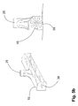
- Fig. 6 illustrated third embodiment differs from the second embodiment in that here the Saugleistenabitese 15, 17 are arranged such that they overlap in a movement of the floor cleaning machine 1 "in the direction of travel F areas overlap or at least directly adjacent to each other 19 facing end of the second Saugleistenabitess 17 relative to the first Saugleistenabitess 15 seen in the direction of travel F offset to the rear.
- the receiving device and the conveying device separate from the suction strip now allow the coarse dirt to be conveyed into the dirt collecting device independently of the suction strips the suction power of the suction bars is reduced and under these no sufficient negative pressure occurs, in particular to absorb particulate matter without interrupting or at least restricting particulate matter production.
Abstract
Description
Die vorliegende Erfindung betrifft eine Bodenreinigungsmaschine mit einem Fahrgestell, das derart ausgestaltet ist, dass die Bodenreinigungsmaschine in einer Fahrtrichtung über eine zu reinigenden Bodenfläche bewegt werden kann, wobei das Fahrgestell in Bezug auf die Fahrtrichtung eine erste und eine zweite Seite aufweist, mit einer Schmutzsammeleinrichtung, mit einer Saugleiste, die an dem Fahrgestell oberhalb der zu reinigenden Bodenfläche angeordnet ist und die eine sich entlang der Saugleiste erstreckende zur Bodenfläche hin weisende Öffnung aufweist, wobei die Saugleiste über wenigstens eine Leitung mit der Schmutzsammeleinrichtung verbunden ist, wobei ein erstes Gebläse vorgesehen ist, das eine Strömung von der Saugleiste durch die erste Leitung in die Schmutzsammeleinrichtung erzeugt, wobei die Saugleiste einen ersten Saugleistenabschnitt und einen zweiten Saugleistenabschnitt aufweist, die sich von der Saugleistenmitte erstrecken, wobei sich der erste Saugleistenabschnitt von der Saugleistenmitte nach außen nach vorne zu der ersten Seite des Fahrgestells hin erstreckt und wobei sich der zweite Saugleistenabschnitt von der Saugleistenmitte nach außen nach vorne zu der zweiten Seite des Fahrgestells hin erstreckt.The present invention relates to a floor cleaning machine with a chassis, which is designed such that the floor cleaning machine can be moved in a direction of travel over a floor surface to be cleaned, wherein the chassis with respect to the direction of travel has a first and a second side, with a dirt collector, a squeegee disposed on the chassis above the floor surface to be cleaned and having an opening extending along the squeegee facing the floor surface, the squeegee being connected to the dirt collector via at least one conduit, a first fan being provided; producing a flow from the squeegee through the first conduit into the debris collection means, the squeegee having a first squeegee section and a second squeegee section extending from the squeegee center, the first squeegee section being the first squeegee section tt extends outwardly from the squeegee center forwardly toward the first side of the chassis, and wherein the second squeegee section extends outwardly from the squeegee center outward toward the second side of the chassis.
Aus dem Stand der Technik sind Bodenreinigungsmaschinen bekannt, bei denen an einem Fahrgestell höhenverstellbar angebrachte, rotierend angetriebene Tellerbesen vorgesehen sind. Dabei weisen die Tellerbesen auf einer runden Tragplatte angeordnete Borsten auf und sind derart am Fahrgestell der Bodenreinigungsmaschine angebracht, dass sie in Fahrtrichtung gesehen vor der Maschine auf der zu reinigenden Bodenfläche vorhandenen Schmutz in den Bereich zwischen den Tellerbesen kehren. Dadurch bildet sich eine so genannte Schwade aus Schmutz, die durch eine maschinenmittig angebrachte Aufnahmeeinrichtung in Form eines Saugmundes aufgenommen werden kann. Der Saugmund wird in geringem Abstand über der zu reinigenden Bodenfläche geführt und hat eine in Fahrtrichtung gesehen nach vorne weisende Öffnung. Mit der Saugdüse ist ein Schmutzbehälter verbunden, wobei des Weiteren ein Gebläse vorhanden ist, durch das in dem Schmutzbehälter ein Unterdruck erzeugt wird, so dass eine Luftströmung von dem Saugmund in den Schmutzbehälter entsteht, die die Schwade mitreißt.Floor cleaning machines are known from the prior art, in which mounted on a chassis height adjustable, rotating driven disc brushes are provided. In this case, the plate brooms on a round support plate arranged bristles and are mounted on the chassis of the floor cleaning machine that they see in the direction of travel before the machine on the floor surface to be cleaned dirt in the area between the plate brooms. As a result, a so-called swath of dirt forms, which can be accommodated by a receiving device mounted centrally in the form of a suction mouth. The suction mouth is guided at a small distance above the floor surface to be cleaned and has a seen in the direction of travel forward facing opening. With the suction nozzle, a dirt container is connected, wherein further a blower is present, through which a negative pressure is generated in the dirt container, so that an air flow from the suction mouth is formed in the dirt container, which entrains the swath.
Nachteilhaft bei derartigen Bodenreinigungsmaschinen, wie sie beispielsweise in der
Hierzu ist es aus der
Wenn sich die Bodenreinigungsmaschine in Fahrtrichtung über die zu reinigende Bodenfläche bewegt, wird gröberer Schmutz, der nicht unter die Saugleiste selbst gerät, vor dieser her geschoben und aufgrund der V-Form zur Mitte vor die Öffnung befördert. Wenn dieser gröbere Schmutz eingesaugt werden soll, bedient der Fahrer der Bodenreinigungsmaschine eine Betätigungsvorrichtung, sodass die Verschlussvorrichtung die Öffnung freigibt und dieser grobe Schmutz mittels der Saugvorrichtung ebenfalls eingesaugt wird.When the floor cleaning machine moves in the direction of travel over the floor surface to be cleaned, coarse dirt, which does not get under the squeegee itself, pushed in front of this and transported due to the V-shape to the center in front of the opening. If this coarse dirt is to be sucked in, the driver of the floor cleaning machine operates an actuating device, so that the closure device releases the opening and this coarse dirt is also sucked in by means of the suction device.
An einer derartigen Anordnung ist jedoch nachteilhaft, dass immer dann, wenn die mittig angeordnete Verschlussvorrichtung geöffnet wird, der Luftstrom in den Saugleisten zusammenbricht und der auf der zu reinigenden Bodenfläche unterhalb der Saugleisten liegende feinere Schmutz nicht mehr eingesaugt wird. Dies hat zur Folge, dass immer dann, wenn die Öffnung geöffnet wird, ein Streifen von feinem Schmutz auf der zu reinigenden Bodenfläche verbleibt, während sich das Fahrzeug weiterbewegt. Um dies zu vermeiden, ist es bei der bekannten Bodenreinigungsmaschine daher erforderlich, die Fahrt zu stoppen, wenn die Verschlussvorrichtung betätigt und gröberer Schmutz aufgenommen werden soll.However, such an arrangement is disadvantageous in that whenever the centrally arranged closure device is opened, the air flow collapses into the suction strips and the finer dirt lying on the bottom surface to be cleaned below the suction strips is no longer sucked in. As a result, whenever the opening is opened, a strip of fine dirt remains on the floor surface to be cleaned as the vehicle moves on. In order to avoid this, it is therefore necessary in the known floor cleaning machine to stop the drive when the shutter device is actuated and coarser dirt is to be absorbed.
Ein weiterer Nachteil der in der
Ausgehend von diesem Stand der Technik ist es daher die Aufgabe der vorliegenden Erfindung, eine Bodenreinigungsmaschine bereitzustellen, die zum einen geeignet ist, auch Feinstaub mit einer Partikelgröße von etwa 10 µm aufzunehmen und die zum anderen auch gröberen Schmutz einsaugen kann, ohne dass es dabei erforderlich ist, die Fahrt der Bodenreinigungsmaschine zu stoppen.Based on this prior art, it is therefore the object of the present invention to provide a floor cleaning machine, which is suitable for one, also to absorb fine dust with a particle size of about 10 microns and on the other can suck in coarser dirt, without it being necessary is to stop the ride of the floor cleaning machine.
Diese Aufgabe wird dadurch gelöst, dass eine Aufnahmeeinrichtung vorgesehen ist, die benachbart zu der Saugleistenmitte zur Aufnahme von Grobschmutz von der zu reinigenden Bodenfläche angeordnet ist, und dass die Aufnahmeeinrichtung über eine getrennt von der Saugleitung ausgebildete Fördereinrichtung mit der Schmutzsammeleinrichtung verbunden ist.This object is achieved in that a receiving device is provided, which is arranged adjacent to the Saugleistenmitte for receiving coarse dirt from the bottom surface to be cleaned, and that the receiving device is connected via a separately formed from the suction conveyor with the dirt collecting device.
Da sich der erste und der zweite Saugleistenabschnitt von der Saugleistenmitte aus nach außen und nach vorne hin erstrecken, wird während der Bewegung der Bodenreinigungsmaschine in Fahrtrichtung Grobschmutz an den Saugleistenabschnitten zur Saugleistenmitte befördert. Hierbei können sich die Saugleistenabschnitte in einer bevorzugten Ausführungsform insbesondere V-förmig von der Saugleistenmitte in Fahrtrichtung gesehen nach vorne erstrecken. Dabei ist die Saugleistenmitte nicht notwendigerweise mittig in Bezug auf die Bodenreinigungsmaschine angeordnet, sondern kann auch seitlich versetzt dazu positioniert sein.As the first and second squeegee sections extend outwardly and forwardly from the squeegee center, coarse dirt is conveyed to the squeegee section toward the squeegee center during travel of the floor cleaning machine in the direction of travel. Here, the Saugleistenabschnitte in a preferred embodiment, in particular V-shaped extending from the Saugleistenmitte seen in the direction of travel forward. In this case, the Saugleistenmitte is not necessarily located centrally with respect to the floor cleaning machine, but may also be laterally offset to be positioned.
Durch die von der Saugleiste getrennte, bevorzugt mittig angeordnete Aufnahmeeinrichtung und die Fördereinrichtung wird nunmehr ermöglicht, dass dieser Grobschmutz unabhängig von dem Betrieb der Saugleisten in die Schmutzsammeleinrichtung befördert wird. Damit tritt insbesondere nicht der Effekt ein, dass bei der Aufnahme von Grobschmutz die Saugleistung der Saugleisten verringert wird und unter diesen kein ausreichender Unterdruck auftritt, um Feinstaub aufzunehmen. Bei der erfindungsgemäßen Bodenreinigungsmaschine wird somit ermöglicht, ohne Unterbrechung der Fahrt der Maschine auch Grobschmutz in die Schmutzsammeleinrichtung zu fördern.By separated from the squeegee, preferably centrally arranged receiving device and the conveyor is now possible that this coarse dirt is transported independently of the operation of the suction in the dirt collecting device. In particular, this does not have the effect of reducing the suction power of the suction bars when taking up coarse dirt, and under these there is no sufficient negative pressure to absorb fine dust. In the floor cleaning machine according to the invention is thus made possible to promote even without interruption of the drive of the machine coarse dirt in the dirt collecting device.
In einer bevorzugten Ausführungsform der Erfindung weist die Schmutzsammeleinrichtung einen ersten Schmutzbehälter und einen zweiten Schmutzbehälter auf, wobei die Saugleiste mit dem ersten Schmutzbehälter verbunden ist und die Fördereinrichtung mit dem zweiten Schmutzbehälter. Auf diese Weise können der Grobschmutz und der Feinstaub getrennt gesammelt werden.In a preferred embodiment of the invention, the dirt collecting device has a first dirt container and a second dirt container, wherein the suction strip with the first dirt container is connected and the conveyor with the second dirt container. In this way, the coarse dirt and fine dust can be collected separately.
Wenn der Grobschmutz mechanisch in die Schmutzsammeleinrichtung gefördert werden soll, kann die Fördereinrichtung als Förderschnecke oder als Förderband ausgebildet sein. Derartige Fördereinrichtungen sind mit dem Vorteil verbunden, dass sie vergleichsweise wenig Energie benötigen.If the coarse dirt is to be conveyed mechanically into the dirt collecting device, the conveying device can be designed as a screw conveyor or as a conveyor belt. Such conveyors are associated with the advantage that they require relatively little energy.
In bevorzugter Weise ist die Aufnahmeeinrichtung aber als oberhalb der Ebene der zu reinigenden Oberfläche angeordnete Saugdüse ausgebildet, und die Saugdüse ist mit der Schmutzsammeleinrichtung verbunden. Ferner ist hier die Fördereinrichtung als ein zweites Gebläse und eine Saugdüsenleitung ausgebildet, wobei das zweite Gebläse eine Luftströmung von der Saugdüse in die Schmutzsammeleinrichtung erzeugt.Preferably, however, the receiving device is designed as above the plane of the surface to be cleaned arranged suction nozzle, and the suction nozzle is connected to the dirt collecting device. Furthermore, here the conveyor is designed as a second fan and a suction nozzle line, wherein the second fan generates an air flow from the suction nozzle into the dirt collecting device.
In diesem Fall wird auch der Grobschmutz pneumatisch über die Saugdüse mittels einer Luftströmung in die Schmutzsammeleinrichtung befördert. Allerdings sind das erste und das zweite Gebläse unabhängig voneinander und können an die jeweiligen Anforderungen in Hinblick auf den jeweils geförderten Schmutz angepasst werden. Insbesondere kann das erste Gebläse derart ausgestaltet sein, dass dieses im Bereich der Saugleisten einen hohen Unterdruck erzeugt. Es ist aber nicht erforderlich, dass das erste Gebläse auch einen hohen Volumenstrom fördert. Im Gegensatz dazu ist das zweite Gebläse ausgelegt, einen hohen Volumenstrom zu fördern, der sich durch den im Vergleich zu den Saugleisten vergleichsweise großen Öffnungsquerschnitt der Saugdüse ergibt, die in der Lage sein muss, auch größere Gegenstände wie Dosen einzusaugen. Auch hier kommt es nicht dazu, dass der Betrieb der Fördereinrichtung für Grobschmutz die Saugleistung im Bereich der Saugleisten beeinträchtigt.In this case, the coarse dirt is conveyed pneumatically via the suction nozzle by means of an air flow in the dirt collecting device. However, the first and the second blower are independent of each other and can be adapted to the respective requirements with regard to the respectively conveyed dirt. In particular, the first fan may be designed such that it generates a high negative pressure in the region of the suction strips. However, it is not necessary that the first fan also promotes a high volume flow. In contrast, the second blower is designed to promote a high flow rate, which results from the comparatively large compared to the suction strip opening cross section of the suction nozzle, which must be able to suck even larger items such as cans. Again, it does not happen that the operation of the conveyor for coarse dirt affects the suction in the area of the suction.
Um sicherzustellen, dass die Bodenfläche vollständig von Feinstaub gereinigt wird, können in einer bevorzugten Ausführungsform in den Saugleistenabschnitten rotierend angetriebene Bürsten vorgesehen sein, die sich entlang der Saugleistenabschnitte erstrecken und mit der zu reinigenden Bodenfläche eingreifen können.In order to ensure that the floor surface is completely cleaned of fine dust, in a preferred embodiment, in the Saugleistenabschnitten rotatably driven brushes may be provided, which extend along the Saugleistenabschnitte and can engage with the floor surface to be cleaned.
Weiterhin können der erste Saugleistenabschnitt und der zweite Saugleistenabschnitt voneinander getrennt ausgebildet sein, wobei der erste Saugleistenabschnitt über eine erste Leitung und der zweite Saugleistenabschnitt über eine zweite Leitung mit dem ersten Gebläse verbunden sind. In diesem Fall umgibt der erste Saugleistenabschnitt ein erstes Innenvolumen und der zweite Saugleistenabschnitt ein zweites Innenvolumen, und sowohl der erste als auch der zweite Saugleistenabschnitt weisen eine sich entlang des Saugleistenabschnitts erstreckende und zur zu reinigenden Bodenfläche weisende Öffnung auf, durch die mit Feinstaub beladene Luft in das jeweilige Innenvolumen eintreten kann. Die Saugleistenabschnitte sind unabhängig voneinander beweglich ausgebildet, sodass eine unabhängige Anlenkung der Saugleistenabschnitte an dem Fahrgestell ermöglicht wird. Hierdurch wiederum wird erreicht, dass die Saugleistenabschnitte während der Fahrt besser der Kontur der zu reinigen Bodenfläche folgen können und dadurch ein besseres Reinigungsergebnis erzielt wird. Hier ist es insbesondere vorteilhaft, wenn die Saugleistenabschnitte schwenkbar in einer Ebene, die senkrecht zur Ebene der zu reinigen Bodenfläche verläuft, an dem Fahrgestell angelenkt sind.Furthermore, the first Saugleistenabschnitt and the second Saugleistenabschnitt be formed separately from each other, wherein the first Saugleistenabschnitt via a first line and the second Saugleistenabschnitt are connected via a second line to the first fan. In this case, the first squeegee portion surrounds a first interior volume and the second squeegee portion has a second interior volume, and both the first and second squeegee portions have an opening extending along the squeegee portion and facing the bottom surface to be cleaned by the particulate laden air the respective internal volume can occur. The Saugleistenabschnitte are designed to be movable independently of each other, so that an independent articulation of the Saugleistenabschnitte is made possible on the chassis. In turn, this ensures that the Saugleistenabschnitte while driving better the contour of the ground surface to clean can follow and thereby a better cleaning result is achieved. Here, it is particularly advantageous if the Saugleistenabschnitte pivotally in a plane which is perpendicular to the plane of the floor surface to be cleaned, are hinged to the chassis.
Außerdem kann durch eine bewegliche Anlenkung der Saugleistenabschnitte an dem Fahrgestell die Breite des Streifens eingestellt werden, der von der Saugleiste während der Fahrt überstrichen und damit gereinigt wird. Hier sind die Saugleistenabschnitte bevorzugt an dem Fahrgestell schwenkbar in der Ebene der zu reinigenden Bodenfläche angelenkt.In addition, the width of the strip can be adjusted by a movable articulation of the Saugleistenabschnitte on the chassis, which is swept by the squeegee while driving and cleaned it. Here, the Saugleistenabschnitte are preferably hinged to the chassis pivotally in the plane of the floor surface to be cleaned.
Um zum einen ein gutes Reinigungsergebnis im Hinblick auf Feinstaub über die gesamte Breite der Saugleiste zu erreichen und um zum anderen den Grobschmutz zuverlässig aufnehmen zu können, hat es sich als vorteilhaft erwiesen, wenn in der Saugleistenmitte ein Rampenelement vorgesehen ist und die Saugdüse in Fahrtrichtung gesehen hinter der Rampe angeordnet ist. Dabei weist das Rampenelement eine nach vorne weisende Schrägfläche auf. Hierbei können die Saugleistenabschnitte insbesondere derart ausgebildet sein, dass die Höhe des ersten und zweiten Saugleistenabschnitts zur Saugleistenmitte hin abnimmt.In order to achieve a good cleaning result in terms of particulate matter over the entire width of the squeegee and to be able to reliably absorb coarse dirt on the other hand, it has proven to be advantageous if a ramp element is provided in the Saugleistenmitte and seen the suction nozzle in the direction of travel is arranged behind the ramp. In this case, the ramp element has a forwardly facing inclined surface. In this case, the Saugleistenabschnitte can in particular be designed such that the height of the first and second Saugleistenabschnitts decreases to Saugleistenmitte out.
Auf diese Weise kann Grobschmutz, der zur Saugleistenmitte bewegt worden ist, über die Saugleiste hinweg zur Saugdüse gelangen, während es keinen Bereich gibt, der nicht auch von der Saugleiste überstrichen wird.In this way, coarse dirt, which has been moved to the Saugleistenmitte, get over the squeegee away to the suction nozzle, while there is no area that is not swept by the squeegee.
Im Folgenden wird die vorliegende Erfindung anhand einer Zeichnung erläutert, die lediglich bevorzugte Ausführungsbeispiele zeigt. In der Zeichnung zeigen
- Fig. 1
- ein erstes Ausführungsbeispiel der vorliegenden Erfindung in perspektivischer Ansicht,
- Fig. 2
- die Saugleistenanordnung des ersten Ausführungsbeispiels in vergrößerter Darstellung,
- Fig. 3
- die Saugdüsenanordnung des ersten Ausführungsbeispiels in vergrößerter Darstellung,
- Fig. 4
- ein zweites Ausführungsbeispiel gemäß der vorliegenden Erfindung in perspektivischer Darstellung,
- Fig. 5a
- die Saugleistenanordnung des zweiten Ausführungsbeispiels in Vorderansicht,
- Fig. 5b
- eine bevorzugte Ausführung der Saugleistenabschnitte des zweiten Ausführungsbeispiels in perspektivischer Darstellung sowie im Schnitt zeigt und
- Fig. 6
- ein drittes Ausführungsbeispiel der vorliegenden Erfindung in perspektivischer Darstellung.
- Fig. 1
- A first embodiment of the present invention in perspective view,
- Fig. 2
- the Saugleistenanordnung the first embodiment in an enlarged view,
- Fig. 3
- the suction nozzle arrangement of the first embodiment in an enlarged view,
- Fig. 4
- A second embodiment according to the present invention in a perspective view,
- Fig. 5a
- the Saugleistenanordnung of the second embodiment in front view,
- Fig. 5b
- a preferred embodiment of the Saugleistenabschnitte of the second embodiment in a perspective view and in section and shows
- Fig. 6
- A third embodiment of the present invention in perspective.
In den hier beschriebenen bevorzugten Ausführungsbeispielen ist die Bodenreinigungsmaschine 1 als eine selbstfahrende Reinigungsmaschine mit einer Fahrerkabine 5 und einem nicht näher dargestellten Antrieb ausgestaltet, wobei es jedoch auch denkbar ist, dass die Bodenreinigungsmaschine 1 durch eine Bedienperson geschoben wird und nicht selbst angetrieben ist.In the preferred embodiments described here, the floor cleaning machine 1 is designed as a self-propelled cleaning machine with a driver's cab 5 and a drive, not shown, but it is also conceivable that the floor cleaning machine 1 is pushed by an operator and not driven itself.
Im hinteren Teil der Bodenreinigungsmaschine ist eine Schmutzsammeleinrichtung 7 angeordnet, die in dem vorliegenden Ausführungsbeispiel einen ersten Schmutzbehälter 9 und einen zweiten Schmutzbehälter 11 umfasst (siehe
In Fahrtrichtung F gesehen am vorderen Teil der Bodenreinigungsmaschine ist unmittelbar oberhalb der zu reinigenden Oberfläche eine Saugleistenanordnung 13 angebracht, die einen ersten Saugleistenabschnitt 15 und einen zweiten Saugleistenabschnitt 17 umfasst. Dabei erstreckt sich der erste Saugleistenabschnitt 15 von der Saugleistenmitte 19 nach vorne zu der ersten, rechten Seite des Fahrgestells, während sich der zweite Saugleistenabschnitt 17 von der Saugleistenmitte 19 nach vorne zur zweiten, linken Seite des Fahrgestells erstreckt. Daher bilden die Saugleistenabschnitte 15, 17 in dieser bevorzugten Ausführungsform eine in Fahrtrichtung F gesehen nach vorne geöffnete V-förmige Anordnung.In the direction of travel F seen at the front of the floor cleaning machine, a
Es ist jedoch auch denkbar, dass sich die Saugleistenabschnitte 15, 17 in gebogener Form von der Saugleistenmitte 19 zu den jeweiligen Seiten des Fahrgestells hin nach vorne erstrecken. In jedem Fall muss aber gewährleistet sein, dass grober Schmutz, der sich zwischen den seitlichen äußeren Enden der Saugleistenabschnitte 15, 17 befindet, bei einer Bewegung der Bodenreinigungsmaschine 1 in Fahrtrichtung F zur Saugleistenmitte 19 hin gefördert wird.However, it is also conceivable that the
Die Saugleistenabschnitte 15, 17 haben ein Gehäuse, das ein erstes bzw. zweites Innenvolumen umgibt und eine sich entlang des jeweiligen Saugleistenabschnitts 15, 17 erstreckende, zur zu reinigenden Bodenfläche hin weisende Öffnung aufweist. Das erste Innenvolumen des ersten Saugleistenabschnitts 15 ist über eine erste Leitung 21 mit dem ersten Schmutzbehälter 9 verbunden. In ähnlicher Weise ist das zweite Innenvolumen des zweiten Saugleistenabschnitts 17 über eine zweite Leitung 23 ebenfalls mit dem ersten Schmutzbehälter 9 verbunden. An dem ersten Schmutzbehälter 9 wiederum ist ein erstes Gebläse 24 vorgesehen, durch das in dem ersten Schmutzbehälter 9 ein Unterdruck erzeugt werden kann, sodass eine Luftströmung von den in den Saugleistenabschnitten 15, 17 vorgesehenen Öffnungen in den ersten Schmutzbehälter 9 erzeugt wird. Somit kann mittels der Saugleiste 13 auf der zu reinigenden Bodenfläche vorhandener Staub und insbesondere Feinstaub mit einer Korngröße von weniger als 10 µm eingesaugt werden, ohne dass dieser beim Reinigungsvorgang aufgewirbelt wird und anschließend nicht von der Maschine erfast werden kann.The
Während in diesem Ausführungsbeispiel beide Saugleistenabschnitte 15, 17 mit einem gemeinsamen Schmutzbehälter 9 verbunden sind, ist es auch möglich, das der Schmutzbehälter zweiteilig ausgebildet ist. In diesem Fall ist für jeden Saugleistenabschnitt ein separater Teil des Schmutzbehälters vorgesehen.While in this embodiment, both
Wie insbesondere
An den Saugleistenabschnitten 15, 17 sind zudem Stützräder 27 vorgesehen, die die Saugleistenabschnitte 15, 17 in einem definierten Abstand zu der zu reinigenden Bodenfläche halten. Die Saugleistenabschnitte 15, 17 sind ferner an einer Aufhängung 29 derart angebracht, dass sie einerseits in der Ebene der zu reinigenden Bodenfläche verschwenkt werden können und sich damit der Winkel verändern lässt, unter dem die Saugleistenabschnitte 15, 17 zueinander verlaufen. Dadurch wird ermöglicht, die Breite des von den Saugleistenabschnitten 15, 17 überstrichenen Bereichs der Bodenfläche zu variieren.At the
Andererseits sind die Saugleistenabschnitte 15, 17 bevorzugter Weise zusätzlich in einer Ebene schwenkbar, die senkrecht zu der zu reinigenden Bodenfläche verläuft, sodass die Saugleistenabschnitte 15, 17 auch Unebenheiten in der zu reinigenden Bodenfläche folgen können.On the other hand, the
Hinter der Saugleistenanordnung 13 ist eine Saugdüse 31 zur Aufnahme von Grobschmutz von der zu reinigenden Bodenfläche angeordnet. Wie insbesondere
Die Saugdüse 31 dient hier als Aufnahmeeinrichtung für Grobschmutz, der über das Rampenelement 25 hinweg gelaufen ist und sich auf der zu reinigenden Bodenfläche befindet, wobei dieser dann eingesaugt und mittels der Saugdüsenleitung 33 und des zweiten Gebläses 35, die als Fördereinrichtung dienen, in den zweiten Schmutzbehälter 11 gefördert wird. Daher ist im vorliegenden Ausführungsbeispiel die Aufnahmeeinrichtung als Saugdüse 31 und die Fördereinrichtung als Saugdüsenleitung 33 bzw. Gebläse 35 ausgebildet.The
Es ist aber auch denkbar, dass statt einer pneumatischen Förderung des Grobschmutzes eine mechanische Förderung vorgesehen ist. Beispielsweise könnte ein Förderband oder eine Förderschnecke verwendet werden, um den Grobschmutz von der zu reinigenden Bodenfläche in den zweiten Schmutzbehälter 11 zu befördern. Außerdem ist es auch möglich, dass ein Besenförderer als Aufnahme und Fördereinrichtung vorgesehen ist.But it is also conceivable that instead of a pneumatic conveying of the coarse dirt, a mechanical promotion is provided. For example, a conveyor belt or auger could be used to convey the coarse debris from the floor surface to be cleaned into the
Im Betrieb bewegt sich die Bodenreinigungsmaschine 1 entlang der Fahrtrichtung F über die zu reinigende Bodenfläche, wobei sich auf dieser befindlicher Feinstaub von den Saugleistenabschnitten 15, 17 eingesaugt und in dem ersten Schmutzbehälter 9 gesammelt wird. Gleichzeitig wird Grobschmutz, der sich auf der zu reinigenden Bodenfläche befindet, durch die V-förmige Anordnung der Saugleistenabschnitte 15, 17 zur Saugleistenmitte 19 gefördert und gelangt über die Saugleistenabschnitte 15, 17 hinweg vor die Öffnung 32 der Saugdüse 31 und wird anschließend von dieser eingesaugt und in den zweiten Schmutzbehälter 11 gefördert. Da die Saugleiste 15, 17 einerseits und die Aufnahmeeinrichtung in Form der Saugdüse 31 andererseits unabhängig voneinander betrieben werden, stört das Fördern des Grobschmutzes in den zweiten Schmutzbehälter 11 nicht das Absaugen von Feinstaub. Dadurch muss die Fahrt der Bodenreinigungsmaschine 1 nicht gestoppt werden, wenn Grobschmutz aufgenommen werden soll. Insbesondere tritt nicht der Fall ein, dass die Höhe des Unterdrucks in der Saugleistenanordnung 13 durch die Förderung von Grobschmutz beeinflusst wird und zusammenbrechen kann, was dazu führen würde, dass bei sich bewegender Bodenreinigungsmaschine immer dann Bereiche, die nicht ausreichend gereinigt sind, verbleiben, wenn der Unterdruck nicht ausreichend stark ist.In operation, the floor cleaning machine 1 moves along the direction of travel F over the floor surface to be cleaned, being sucked on this particulate matter from the
Wie in
Das in den
Das in
Damit wird Grobschmutz, der von dem ersten Saugleistenabschnitt 15 erfasst wird, zunächst zur Saugleistenmitte 19 gefördert, gelangt an den zweiten Saugleistenabschnitt 17 und wird dann weiter zur Saugdüse 31 geführt. Damit besteht bei dieser Anordnung der Vorteil, dass einerseits die gesamte Arbeitsbreite der Bodenreinigungsmaschine 1" von den Saugleistenabschnitten 15, 17 überstrichen wird, andererseits aber Grobschmutz nicht im Bereich der Saugleistenmitte 19 über diese hinweg gefördert werden muss, um zu der Aufnahmeeinrichtung zu gelangen.Thus, coarse dirt, which is detected by the
Bei den erfindungsgemäßen Bodenreinigungsmaschinen 1, 1', 1" ermöglicht die von der Saugleiste getrennte Aufnahmeeinrichtung und die Fördereinrichtung nunmehr, dass der Grobschmutz unabhängig von den Saugleisten in die Schmutzsammeleinrichtung befördert wird. Damit kann der Effekt nicht mehr auftreten, dass bei der Aufnahme von Grobschmutz die Saugleistung der Saugleisten verringert wird und unter diesen kein ausreichender Unterdruck auftritt, um insbesondere Feinstaub aufzunehmen. Bei der erfindungsgemäßen Bodenreinigungsmaschinen 1, 1' wird somit ermöglicht, ohne Unterbrechung der Fahrt der Maschine auch Grobschmutz in die Schmutzsammeleinrichtung zu fördern, ohne dass dabei die Feinstaubförderung unterbrochen oder zumindest eingeschränkt wird.In the floor cleaning machines 1, 1 ', 1 "according to the invention, the receiving device and the conveying device separate from the suction strip now allow the coarse dirt to be conveyed into the dirt collecting device independently of the suction strips the suction power of the suction bars is reduced and under these no sufficient negative pressure occurs, in particular to absorb particulate matter without interrupting or at least restricting particulate matter production.
Claims (12)
mit einer Schmutzsammeleinrichtung (7),
mit einer Saugleiste, die an dem Fahrgestell oberhalb der zu reinigenden Bodenfläche angeordnet ist und die eine sich entlang der Saugleiste erstreckende zur Bodenfläche hin weisende Öffnung aufweist, wobei die Saugleiste über eine erste Leitung (21, 23) mit der Schmutzsammeleinrichtung (7) verbunden ist,
wobei ein erstes Gebläse (24) vorgesehen ist, das eine Strömung von der Saugleiste durch die erste Leitung (21, 23) in die Schmutzsammeleinrichtung (7) erzeugt,
wobei die Saugleiste einen ersten Saugleistenabschnitt (15) und einen zweiten Saugleistenabschnitt (17) aufweist, die sich von der Saugleistenmitte (19) erstrekken,
wobei sich der erste Saugleistenabschnitt (15) von der Saugleistenmitte (19) nach außen nach vorne zu der ersten Seite des Fahrgestells hin erstreckt und
wobei sich der zweite Saugleistenabschnitt (17) von der Saugleistenmitte (19) nach außen nach vorne zu der zweiten Seite des Fahrgestells hin erstreckt,
dadurch gekennzeichnet,
dass eine Aufnahmeeinrichtung (31) vorgesehen ist, die benachbart zu der Saugleistenmitte (19) zur Aufnahme von Grobschmutz von der zu reinigenden Bodenfläche angeordnet ist und
dass die Aufnahmeeinrichtung (31) über eine getrennt von der ersten Leitung (21, 23) ausgebildete Fördereinrichtung (33) mit der Schmutzsammeleinrichtung (7) verbunden ist.Floor cleaning machine with a chassis, which is configured such that the floor cleaning machine (1) in a direction of travel (F) can be moved over a floor surface to be cleaned, wherein the chassis with respect to the direction of travel (F) has a first and a second side,
with a dirt collecting device (7),
with a squeegee which is arranged on the chassis above the floor surface to be cleaned and which has an opening extending along the squeegee facing the bottom surface opening, wherein the squeegee is connected via a first line (21, 23) with the dirt collecting means (7) .
wherein a first fan (24) is provided which generates a flow from the squeegee through the first conduit (21, 23) into the soil collecting means (7),
the squeegee having a first squeegee section (15) and a second squeegee section (17) extending from the squeegee center (19),
wherein the first squeegee portion (15) extends outwardly from the squeegee center (19) out forward to the first side of the chassis and
wherein the second squeegee portion (17) extends outwardly from the squeegee center (19) forwardly toward the second side of the chassis,
characterized,
that a receiving device (31) is provided, which is arranged adjacent to the Saugleistenmitte (19) for receiving coarse dirt from the floor surface to be cleaned and
in that the receiving device (31) is connected to the dirt collecting device (7) via a conveying device (33) formed separately from the first line (21, 23).
dass die Saugleiste mit dem ersten Schmutzbehälter (9) verbunden ist und
dass die Fördereinrichtung (33) mit dem zweiten Schmutzbehälter (11) verbunden ist.Floor cleaning machine according to claim 1 or 2, characterized in that the dirt collecting device (7) has a first dirt container (9) and a second dirt container (11),
that the squeegee is connected to the first dirt container (9) and
the conveying device (33) is connected to the second dirt container (11).
dass die Saugdüse (31) mit der Schmutzsammeleinrichtung (7) verbunden ist,
dass die Fördereinrichtung ein zweites Gebläse (35) und eine Saugdüsenleitung (33) umfasst und
dass das zweite Gebläse (35) eine Luftströmung von der Saugdüse (31) in die Schmutzsammeleinrichtung (7) erzeugt.Floor cleaning machine according to one of claims 1 to 3, characterized in that the receiving device is designed as above the plane of the surface to be cleaned arranged suction nozzle (31),
the suction nozzle (31) is connected to the dirt collecting device (7),
in that the delivery device comprises a second blower (35) and a suction nozzle line (33) and
in that the second blower (35) generates an air flow from the suction nozzle (31) into the dirt collecting device (7).
dass der erste und der zweite Saugleistenabschnitt (15, 17) eine sich entlang des Saugleistenabschnitts (15, 17) erstreckende und zur zu reinigenden Bodenfläche weisende Öffnung aufweisen,
dass der erste und der zweite Saugleistenabschnitt (15, 17) unabhängig voneinander beweglich sind,
dass der erste Saugleistenabschnitt (15) über eine erste Leitung (21) mit dem ersten Gebläse (24) verbunden ist und der zweite Saugleistenabschnitt (17) über eine zweite Leitung (23) mit dem ersten Gebläse (24) verbunden ist und
dass die erste und die zweite Leitung (21, 23) von der Fördereinrichtung (33) getrennt sind.Floor cleaning machine according to one of claims 1 to 7, characterized in that the first Saugleistenabschnitt (15) a first inner volume and the second Saugleistenabschnitt (17) surrounds a second inner volume,
the first and second suction strip sections (15, 17) have an opening extending along the suction strip section (15, 17) and facing the bottom surface to be cleaned,
in that the first and second suction strip sections (15, 17) are movable independently of one another,
that the first Saugleistenabschnitt (15) via a first line (21) to the first blower (24) is connected and the second Saugleistenabschnitt (17) via a second line (23) to the first blower (24) is connected and
in that the first and the second line (21, 23) are separated from the conveyor (33).
dass die Saugdüse (31) in Fahrtrichtung gesehen hinter dem Rampenelement (25) angeordnet ist.Floor cleaning machine according to one of claims 8 to 10, characterized in that in the Saugleistenmitte (19) between the first and the second Saugleistenabschnitt (15, 17), a ramp element (25) is provided and
the suction nozzle (31), viewed in the direction of travel, is arranged behind the ramp element (25).
Priority Applications (4)
| Application Number | Priority Date | Filing Date | Title |
|---|---|---|---|
| EP08011059A EP2135540B1 (en) | 2008-06-18 | 2008-06-18 | Floor cleaning machine |
| DE502008001595T DE502008001595D1 (en) | 2008-06-18 | 2008-06-18 | Floor cleaning machine |
| ES08011059T ES2352651T3 (en) | 2008-06-18 | 2008-06-18 | MACHINE FOR CLEANING SOILS. |
| AT08011059T ATE484993T1 (en) | 2008-06-18 | 2008-06-18 | FLOOR CLEANING MACHINE |
Applications Claiming Priority (1)
| Application Number | Priority Date | Filing Date | Title |
|---|---|---|---|
| EP08011059A EP2135540B1 (en) | 2008-06-18 | 2008-06-18 | Floor cleaning machine |
Publications (2)
| Publication Number | Publication Date |
|---|---|
| EP2135540A1 true EP2135540A1 (en) | 2009-12-23 |
| EP2135540B1 EP2135540B1 (en) | 2010-10-20 |
Family
ID=39952188
Family Applications (1)
| Application Number | Title | Priority Date | Filing Date |
|---|---|---|---|
| EP08011059A Not-in-force EP2135540B1 (en) | 2008-06-18 | 2008-06-18 | Floor cleaning machine |
Country Status (4)
| Country | Link |
|---|---|
| EP (1) | EP2135540B1 (en) |
| AT (1) | ATE484993T1 (en) |
| DE (1) | DE502008001595D1 (en) |
| ES (1) | ES2352651T3 (en) |
Cited By (1)
| Publication number | Priority date | Publication date | Assignee | Title |
|---|---|---|---|---|
| WO2016034251A1 (en) * | 2014-09-05 | 2016-03-10 | Alfred Kärcher Gmbh & Co. Kg | Suction bar device for a floor cleaning machine, floor cleaning machine, and method for cleaning tile floors |
Citations (6)
| Publication number | Priority date | Publication date | Assignee | Title |
|---|---|---|---|---|
| GB331631A (en) * | 1928-01-21 | 1930-07-10 | Walter Scott Finnell | |
| US3197798A (en) * | 1963-01-28 | 1965-08-03 | Tennant Co G H | Scrubbing machine |
| DE9415472U1 (en) | 1994-09-23 | 1994-11-17 | Ernst Augl Ges M B H & Co Kg | Mobile device for cleaning and maintaining large areas |
| CA2357057A1 (en) | 2001-08-10 | 2003-02-10 | Roger P. Vanderlinden | Mobile large area surface cleaning apparatus |
| DE202005010880U1 (en) | 2005-07-11 | 2005-11-17 | Bucher-Schörling GmbH | Surface cleaning vehicle for cleaning surfaces e.g. roads, places and open spaces has suction device which has two suction openings arranged behind each other such that different suction flows can be adjusted at openings |
| EP1714603A1 (en) | 2005-04-22 | 2006-10-25 | Hako-Werke GMBH | Floor cleaning machine |
-
2008
- 2008-06-18 DE DE502008001595T patent/DE502008001595D1/en active Active
- 2008-06-18 AT AT08011059T patent/ATE484993T1/en active
- 2008-06-18 EP EP08011059A patent/EP2135540B1/en not_active Not-in-force
- 2008-06-18 ES ES08011059T patent/ES2352651T3/en active Active
Patent Citations (6)
| Publication number | Priority date | Publication date | Assignee | Title |
|---|---|---|---|---|
| GB331631A (en) * | 1928-01-21 | 1930-07-10 | Walter Scott Finnell | |
| US3197798A (en) * | 1963-01-28 | 1965-08-03 | Tennant Co G H | Scrubbing machine |
| DE9415472U1 (en) | 1994-09-23 | 1994-11-17 | Ernst Augl Ges M B H & Co Kg | Mobile device for cleaning and maintaining large areas |
| CA2357057A1 (en) | 2001-08-10 | 2003-02-10 | Roger P. Vanderlinden | Mobile large area surface cleaning apparatus |
| EP1714603A1 (en) | 2005-04-22 | 2006-10-25 | Hako-Werke GMBH | Floor cleaning machine |
| DE202005010880U1 (en) | 2005-07-11 | 2005-11-17 | Bucher-Schörling GmbH | Surface cleaning vehicle for cleaning surfaces e.g. roads, places and open spaces has suction device which has two suction openings arranged behind each other such that different suction flows can be adjusted at openings |
Cited By (1)
| Publication number | Priority date | Publication date | Assignee | Title |
|---|---|---|---|---|
| WO2016034251A1 (en) * | 2014-09-05 | 2016-03-10 | Alfred Kärcher Gmbh & Co. Kg | Suction bar device for a floor cleaning machine, floor cleaning machine, and method for cleaning tile floors |
Also Published As
| Publication number | Publication date |
|---|---|
| ES2352651T3 (en) | 2011-02-22 |
| DE502008001595D1 (en) | 2010-12-02 |
| EP2135540B1 (en) | 2010-10-20 |
| ATE484993T1 (en) | 2010-11-15 |
Similar Documents
| Publication | Publication Date | Title |
|---|---|---|
| EP1564332B1 (en) | Milling machine and method for working the soil | |
| EP0019192B1 (en) | Apparatus for removing dirt from roads or like surfaces by means of a suction air stream | |
| EP2256250B1 (en) | Vehicle to take filler material from a surface | |
| DE102013106996B4 (en) | Waggon cleaning system | |
| DE3133789C2 (en) | ||
| DE4330233C3 (en) | sweeper | |
| EP3315666A1 (en) | Device and method for holding swept items | |
| DE19851128A1 (en) | Pneumatic conveying system, for dust taken up from roads or large surfaces, has dust delivered across pressure or suction air unit in power sweeper with filtering of fine and coarse dust | |
| DE102011082311A1 (en) | Cleaning device for cleaning artificial floor surfaces provided with flooring particles, in particular artificial turf | |
| EP2951352A2 (en) | Cleaning device for a track system and rail vehicle equipped with such a cleaning device | |
| EP2135540B1 (en) | Floor cleaning machine | |
| EP0668402B1 (en) | Collecting container for sweepings and the like | |
| EP2821553B1 (en) | Floor cleaning machine with a brush element arranged in a collecting tray | |
| WO2017009098A1 (en) | Floor cleaning machine and method for operating a floor cleaning machine | |
| EP2690220B1 (en) | Vacuum cleaning machine with a suction device for a side broom | |
| DE202018003947U1 (en) | Saugkehrvorrichtung | |
| EP1023867A2 (en) | Sweeping machine with collecting container | |
| EP0668401A1 (en) | Sweeper | |
| EP2884003B1 (en) | Cleaning device | |
| DE1708659C2 (en) | sweeper | |
| DE19524203A1 (en) | Sweeper with dust extraction | |
| EP3832020B1 (en) | Soil treatment machine with filtered dust extraction with elastically deformable filter housing | |
| EP3808241B1 (en) | Vacuum cleaning robot for autonomous cleaning of floor surfaces of a room | |
| EP3832022B1 (en) | Soil treatment machine with dust extraction and rotating filter cartridges | |
| DE202004002444U1 (en) | Ground cutting machine, e.g. for road surface renewal, has a suction arrangement with a suction blower positioned downstream of a solid material separation arrangement |
Legal Events
| Date | Code | Title | Description |
|---|---|---|---|
| PUAI | Public reference made under article 153(3) epc to a published international application that has entered the european phase |
Free format text: ORIGINAL CODE: 0009012 |
|
| 17P | Request for examination filed |
Effective date: 20090205 |
|
| AK | Designated contracting states |
Kind code of ref document: A1 Designated state(s): AT BE BG CH CY CZ DE DK EE ES FI FR GB GR HR HU IE IS IT LI LT LU LV MC MT NL NO PL PT RO SE SI SK TR |
|
| AX | Request for extension of the european patent |
Extension state: AL BA MK RS |
|
| GRAP | Despatch of communication of intention to grant a patent |
Free format text: ORIGINAL CODE: EPIDOSNIGR1 |
|
| AKX | Designation fees paid |
Designated state(s): AT BE BG CH CY CZ DE DK EE ES FI FR GB GR HR HU IE IS IT LI LT LU LV MC MT NL NO PL PT RO SE SI SK TR |
|
| GRAS | Grant fee paid |
Free format text: ORIGINAL CODE: EPIDOSNIGR3 |
|
| GRAA | (expected) grant |
Free format text: ORIGINAL CODE: 0009210 |
|
| AK | Designated contracting states |
Kind code of ref document: B1 Designated state(s): AT BE BG CH CY CZ DE DK EE ES FI FR GB GR HR HU IE IS IT LI LT LU LV MC MT NL NO PL PT RO SE SI SK TR |
|
| REG | Reference to a national code |
Ref country code: GB Ref legal event code: FG4D Free format text: NOT ENGLISH |
|
| REG | Reference to a national code |
Ref country code: CH Ref legal event code: EP |
|
| REG | Reference to a national code |
Ref country code: CH Ref legal event code: NV Representative=s name: E. BLUM & CO. AG PATENT- UND MARKENANWAELTE VSP |
|
| REG | Reference to a national code |
Ref country code: IE Ref legal event code: FG4D Free format text: LANGUAGE OF EP DOCUMENT: GERMAN |
|
| REF | Corresponds to: |
Ref document number: 502008001595 Country of ref document: DE Date of ref document: 20101202 Kind code of ref document: P |
|
| REG | Reference to a national code |
Ref country code: ES Ref legal event code: FG2A Effective date: 20110210 |
|
| REG | Reference to a national code |
Ref country code: NL Ref legal event code: VDEP Effective date: 20101020 |
|
| LTIE | Lt: invalidation of european patent or patent extension |
Effective date: 20101020 |
|
| PG25 | Lapsed in a contracting state [announced via postgrant information from national office to epo] |
Ref country code: NO Free format text: LAPSE BECAUSE OF FAILURE TO SUBMIT A TRANSLATION OF THE DESCRIPTION OR TO PAY THE FEE WITHIN THE PRESCRIBED TIME-LIMIT Effective date: 20110120 Ref country code: LT Free format text: LAPSE BECAUSE OF FAILURE TO SUBMIT A TRANSLATION OF THE DESCRIPTION OR TO PAY THE FEE WITHIN THE PRESCRIBED TIME-LIMIT Effective date: 20101020 |
|
| REG | Reference to a national code |
Ref country code: IE Ref legal event code: FD4D |
|
| PG25 | Lapsed in a contracting state [announced via postgrant information from national office to epo] |
Ref country code: LV Free format text: LAPSE BECAUSE OF FAILURE TO SUBMIT A TRANSLATION OF THE DESCRIPTION OR TO PAY THE FEE WITHIN THE PRESCRIBED TIME-LIMIT Effective date: 20101020 Ref country code: SI Free format text: LAPSE BECAUSE OF FAILURE TO SUBMIT A TRANSLATION OF THE DESCRIPTION OR TO PAY THE FEE WITHIN THE PRESCRIBED TIME-LIMIT Effective date: 20101020 Ref country code: IS Free format text: LAPSE BECAUSE OF FAILURE TO SUBMIT A TRANSLATION OF THE DESCRIPTION OR TO PAY THE FEE WITHIN THE PRESCRIBED TIME-LIMIT Effective date: 20110220 Ref country code: HR Free format text: LAPSE BECAUSE OF FAILURE TO SUBMIT A TRANSLATION OF THE DESCRIPTION OR TO PAY THE FEE WITHIN THE PRESCRIBED TIME-LIMIT Effective date: 20101020 Ref country code: BG Free format text: LAPSE BECAUSE OF FAILURE TO SUBMIT A TRANSLATION OF THE DESCRIPTION OR TO PAY THE FEE WITHIN THE PRESCRIBED TIME-LIMIT Effective date: 20110120 Ref country code: PT Free format text: LAPSE BECAUSE OF FAILURE TO SUBMIT A TRANSLATION OF THE DESCRIPTION OR TO PAY THE FEE WITHIN THE PRESCRIBED TIME-LIMIT Effective date: 20110221 Ref country code: SE Free format text: LAPSE BECAUSE OF FAILURE TO SUBMIT A TRANSLATION OF THE DESCRIPTION OR TO PAY THE FEE WITHIN THE PRESCRIBED TIME-LIMIT Effective date: 20101020 Ref country code: FI Free format text: LAPSE BECAUSE OF FAILURE TO SUBMIT A TRANSLATION OF THE DESCRIPTION OR TO PAY THE FEE WITHIN THE PRESCRIBED TIME-LIMIT Effective date: 20101020 Ref country code: NL Free format text: LAPSE BECAUSE OF FAILURE TO SUBMIT A TRANSLATION OF THE DESCRIPTION OR TO PAY THE FEE WITHIN THE PRESCRIBED TIME-LIMIT Effective date: 20101020 |
|
| PG25 | Lapsed in a contracting state [announced via postgrant information from national office to epo] |
Ref country code: GR Free format text: LAPSE BECAUSE OF FAILURE TO SUBMIT A TRANSLATION OF THE DESCRIPTION OR TO PAY THE FEE WITHIN THE PRESCRIBED TIME-LIMIT Effective date: 20110121 |
|
| PG25 | Lapsed in a contracting state [announced via postgrant information from national office to epo] |
Ref country code: CZ Free format text: LAPSE BECAUSE OF FAILURE TO SUBMIT A TRANSLATION OF THE DESCRIPTION OR TO PAY THE FEE WITHIN THE PRESCRIBED TIME-LIMIT Effective date: 20101020 Ref country code: IE Free format text: LAPSE BECAUSE OF FAILURE TO SUBMIT A TRANSLATION OF THE DESCRIPTION OR TO PAY THE FEE WITHIN THE PRESCRIBED TIME-LIMIT Effective date: 20101020 Ref country code: EE Free format text: LAPSE BECAUSE OF FAILURE TO SUBMIT A TRANSLATION OF THE DESCRIPTION OR TO PAY THE FEE WITHIN THE PRESCRIBED TIME-LIMIT Effective date: 20101020 |
|
| PLBE | No opposition filed within time limit |
Free format text: ORIGINAL CODE: 0009261 |
|
| STAA | Information on the status of an ep patent application or granted ep patent |
Free format text: STATUS: NO OPPOSITION FILED WITHIN TIME LIMIT |
|
| PG25 | Lapsed in a contracting state [announced via postgrant information from national office to epo] |
Ref country code: SK Free format text: LAPSE BECAUSE OF FAILURE TO SUBMIT A TRANSLATION OF THE DESCRIPTION OR TO PAY THE FEE WITHIN THE PRESCRIBED TIME-LIMIT Effective date: 20101020 Ref country code: DK Free format text: LAPSE BECAUSE OF FAILURE TO SUBMIT A TRANSLATION OF THE DESCRIPTION OR TO PAY THE FEE WITHIN THE PRESCRIBED TIME-LIMIT Effective date: 20101020 Ref country code: PL Free format text: LAPSE BECAUSE OF FAILURE TO SUBMIT A TRANSLATION OF THE DESCRIPTION OR TO PAY THE FEE WITHIN THE PRESCRIBED TIME-LIMIT Effective date: 20101020 Ref country code: RO Free format text: LAPSE BECAUSE OF FAILURE TO SUBMIT A TRANSLATION OF THE DESCRIPTION OR TO PAY THE FEE WITHIN THE PRESCRIBED TIME-LIMIT Effective date: 20101020 |
|
| 26N | No opposition filed |
Effective date: 20110721 |
|
| REG | Reference to a national code |
Ref country code: DE Ref legal event code: R097 Ref document number: 502008001595 Country of ref document: DE Effective date: 20110721 |
|
| PG25 | Lapsed in a contracting state [announced via postgrant information from national office to epo] |
Ref country code: MT Free format text: LAPSE BECAUSE OF FAILURE TO SUBMIT A TRANSLATION OF THE DESCRIPTION OR TO PAY THE FEE WITHIN THE PRESCRIBED TIME-LIMIT Effective date: 20101020 |
|
| BERE | Be: lapsed |
Owner name: HAKO-WERKE G.M.B.H. Effective date: 20110630 |
|
| PG25 | Lapsed in a contracting state [announced via postgrant information from national office to epo] |
Ref country code: BE Free format text: LAPSE BECAUSE OF NON-PAYMENT OF DUE FEES Effective date: 20110630 |
|
| PG25 | Lapsed in a contracting state [announced via postgrant information from national office to epo] |
Ref country code: MC Free format text: LAPSE BECAUSE OF NON-PAYMENT OF DUE FEES Effective date: 20110630 |
|
| PG25 | Lapsed in a contracting state [announced via postgrant information from national office to epo] |
Ref country code: CY Free format text: LAPSE BECAUSE OF EXPIRATION OF PROTECTION Effective date: 20101020 Ref country code: LU Free format text: LAPSE BECAUSE OF NON-PAYMENT OF DUE FEES Effective date: 20110618 |
|
| PG25 | Lapsed in a contracting state [announced via postgrant information from national office to epo] |
Ref country code: TR Free format text: LAPSE BECAUSE OF FAILURE TO SUBMIT A TRANSLATION OF THE DESCRIPTION OR TO PAY THE FEE WITHIN THE PRESCRIBED TIME-LIMIT Effective date: 20101020 |
|
| PG25 | Lapsed in a contracting state [announced via postgrant information from national office to epo] |
Ref country code: HU Free format text: LAPSE BECAUSE OF FAILURE TO SUBMIT A TRANSLATION OF THE DESCRIPTION OR TO PAY THE FEE WITHIN THE PRESCRIBED TIME-LIMIT Effective date: 20101020 |
|
| PGFP | Annual fee paid to national office [announced via postgrant information from national office to epo] |
Ref country code: ES Payment date: 20150512 Year of fee payment: 8 Ref country code: CH Payment date: 20150612 Year of fee payment: 8 |
|
| PGFP | Annual fee paid to national office [announced via postgrant information from national office to epo] |
Ref country code: AT Payment date: 20150527 Year of fee payment: 8 |
|
| REG | Reference to a national code |
Ref country code: FR Ref legal event code: PLFP Year of fee payment: 9 |
|
| REG | Reference to a national code |
Ref country code: CH Ref legal event code: PL |
|
| REG | Reference to a national code |
Ref country code: AT Ref legal event code: MM01 Ref document number: 484993 Country of ref document: AT Kind code of ref document: T Effective date: 20160618 |
|
| PG25 | Lapsed in a contracting state [announced via postgrant information from national office to epo] |
Ref country code: LI Free format text: LAPSE BECAUSE OF NON-PAYMENT OF DUE FEES Effective date: 20160630 Ref country code: CH Free format text: LAPSE BECAUSE OF NON-PAYMENT OF DUE FEES Effective date: 20160630 |
|
| REG | Reference to a national code |
Ref country code: FR Ref legal event code: PLFP Year of fee payment: 10 |
|
| PG25 | Lapsed in a contracting state [announced via postgrant information from national office to epo] |
Ref country code: AT Free format text: LAPSE BECAUSE OF NON-PAYMENT OF DUE FEES Effective date: 20160618 |
|
| REG | Reference to a national code |
Ref country code: FR Ref legal event code: PLFP Year of fee payment: 11 |
|
| PG25 | Lapsed in a contracting state [announced via postgrant information from national office to epo] |
Ref country code: ES Free format text: LAPSE BECAUSE OF NON-PAYMENT OF DUE FEES Effective date: 20160619 |
|
| PGFP | Annual fee paid to national office [announced via postgrant information from national office to epo] |
Ref country code: FR Payment date: 20180511 Year of fee payment: 11 |
|
| PGFP | Annual fee paid to national office [announced via postgrant information from national office to epo] |
Ref country code: GB Payment date: 20180620 Year of fee payment: 11 |
|
| REG | Reference to a national code |
Ref country code: ES Ref legal event code: FD2A Effective date: 20181203 |
|
| GBPC | Gb: european patent ceased through non-payment of renewal fee |
Effective date: 20190618 |
|
| PG25 | Lapsed in a contracting state [announced via postgrant information from national office to epo] |
Ref country code: GB Free format text: LAPSE BECAUSE OF NON-PAYMENT OF DUE FEES Effective date: 20190618 |
|
| PG25 | Lapsed in a contracting state [announced via postgrant information from national office to epo] |
Ref country code: FR Free format text: LAPSE BECAUSE OF NON-PAYMENT OF DUE FEES Effective date: 20190630 |
|
| PGFP | Annual fee paid to national office [announced via postgrant information from national office to epo] |
Ref country code: DE Payment date: 20200602 Year of fee payment: 13 |
|
| PGFP | Annual fee paid to national office [announced via postgrant information from national office to epo] |
Ref country code: IT Payment date: 20200512 Year of fee payment: 13 |
|
| REG | Reference to a national code |
Ref country code: DE Ref legal event code: R119 Ref document number: 502008001595 Country of ref document: DE |
|
| PG25 | Lapsed in a contracting state [announced via postgrant information from national office to epo] |
Ref country code: DE Free format text: LAPSE BECAUSE OF NON-PAYMENT OF DUE FEES Effective date: 20220101 |
|
| PG25 | Lapsed in a contracting state [announced via postgrant information from national office to epo] |
Ref country code: IT Free format text: LAPSE BECAUSE OF NON-PAYMENT OF DUE FEES Effective date: 20210618 |