EP2068236A1 - Computer implemented display, graphical user interface, design and method including scrolling features - Google Patents
Computer implemented display, graphical user interface, design and method including scrolling features Download PDFInfo
- Publication number
- EP2068236A1 EP2068236A1 EP20080169529 EP08169529A EP2068236A1 EP 2068236 A1 EP2068236 A1 EP 2068236A1 EP 20080169529 EP20080169529 EP 20080169529 EP 08169529 A EP08169529 A EP 08169529A EP 2068236 A1 EP2068236 A1 EP 2068236A1
- Authority
- EP
- European Patent Office
- Prior art keywords
- information
- display
- widget
- region
- processing apparatus
- Prior art date
- Legal status (The legal status is an assumption and is not a legal conclusion. Google has not performed a legal analysis and makes no representation as to the accuracy of the status listed.)
- Granted
Links
Images


Classifications
-
- G—PHYSICS
- G06—COMPUTING; CALCULATING OR COUNTING
- G06F—ELECTRIC DIGITAL DATA PROCESSING
- G06F3/00—Input arrangements for transferring data to be processed into a form capable of being handled by the computer; Output arrangements for transferring data from processing unit to output unit, e.g. interface arrangements
- G06F3/01—Input arrangements or combined input and output arrangements for interaction between user and computer
- G06F3/048—Interaction techniques based on graphical user interfaces [GUI]
- G06F3/0487—Interaction techniques based on graphical user interfaces [GUI] using specific features provided by the input device, e.g. functions controlled by the rotation of a mouse with dual sensing arrangements, or of the nature of the input device, e.g. tap gestures based on pressure sensed by a digitiser
- G06F3/0488—Interaction techniques based on graphical user interfaces [GUI] using specific features provided by the input device, e.g. functions controlled by the rotation of a mouse with dual sensing arrangements, or of the nature of the input device, e.g. tap gestures based on pressure sensed by a digitiser using a touch-screen or digitiser, e.g. input of commands through traced gestures
- G06F3/04883—Interaction techniques based on graphical user interfaces [GUI] using specific features provided by the input device, e.g. functions controlled by the rotation of a mouse with dual sensing arrangements, or of the nature of the input device, e.g. tap gestures based on pressure sensed by a digitiser using a touch-screen or digitiser, e.g. input of commands through traced gestures for inputting data by handwriting, e.g. gesture or text
-
- G—PHYSICS
- G06—COMPUTING; CALCULATING OR COUNTING
- G06F—ELECTRIC DIGITAL DATA PROCESSING
- G06F3/00—Input arrangements for transferring data to be processed into a form capable of being handled by the computer; Output arrangements for transferring data from processing unit to output unit, e.g. interface arrangements
- G06F3/01—Input arrangements or combined input and output arrangements for interaction between user and computer
- G06F3/048—Interaction techniques based on graphical user interfaces [GUI]
- G06F3/0481—Interaction techniques based on graphical user interfaces [GUI] based on specific properties of the displayed interaction object or a metaphor-based environment, e.g. interaction with desktop elements like windows or icons, or assisted by a cursor's changing behaviour or appearance
- G06F3/04817—Interaction techniques based on graphical user interfaces [GUI] based on specific properties of the displayed interaction object or a metaphor-based environment, e.g. interaction with desktop elements like windows or icons, or assisted by a cursor's changing behaviour or appearance using icons
-
- G—PHYSICS
- G06—COMPUTING; CALCULATING OR COUNTING
- G06F—ELECTRIC DIGITAL DATA PROCESSING
- G06F3/00—Input arrangements for transferring data to be processed into a form capable of being handled by the computer; Output arrangements for transferring data from processing unit to output unit, e.g. interface arrangements
- G06F3/01—Input arrangements or combined input and output arrangements for interaction between user and computer
- G06F3/048—Interaction techniques based on graphical user interfaces [GUI]
- G06F3/0484—Interaction techniques based on graphical user interfaces [GUI] for the control of specific functions or operations, e.g. selecting or manipulating an object, an image or a displayed text element, setting a parameter value or selecting a range
- G06F3/0485—Scrolling or panning
-
- G—PHYSICS
- G06—COMPUTING; CALCULATING OR COUNTING
- G06F—ELECTRIC DIGITAL DATA PROCESSING
- G06F3/00—Input arrangements for transferring data to be processed into a form capable of being handled by the computer; Output arrangements for transferring data from processing unit to output unit, e.g. interface arrangements
- G06F3/01—Input arrangements or combined input and output arrangements for interaction between user and computer
- G06F3/048—Interaction techniques based on graphical user interfaces [GUI]
- G06F3/0487—Interaction techniques based on graphical user interfaces [GUI] using specific features provided by the input device, e.g. functions controlled by the rotation of a mouse with dual sensing arrangements, or of the nature of the input device, e.g. tap gestures based on pressure sensed by a digitiser
- G06F3/0488—Interaction techniques based on graphical user interfaces [GUI] using specific features provided by the input device, e.g. functions controlled by the rotation of a mouse with dual sensing arrangements, or of the nature of the input device, e.g. tap gestures based on pressure sensed by a digitiser using a touch-screen or digitiser, e.g. input of commands through traced gestures
- G06F3/04886—Interaction techniques based on graphical user interfaces [GUI] using specific features provided by the input device, e.g. functions controlled by the rotation of a mouse with dual sensing arrangements, or of the nature of the input device, e.g. tap gestures based on pressure sensed by a digitiser using a touch-screen or digitiser, e.g. input of commands through traced gestures by partitioning the display area of the touch-screen or the surface of the digitising tablet into independently controllable areas, e.g. virtual keyboards or menus
-
- G—PHYSICS
- G06—COMPUTING; CALCULATING OR COUNTING
- G06F—ELECTRIC DIGITAL DATA PROCESSING
- G06F2203/00—Indexing scheme relating to G06F3/00 - G06F3/048
- G06F2203/048—Indexing scheme relating to G06F3/048
- G06F2203/04803—Split screen, i.e. subdividing the display area or the window area into separate subareas
Definitions
- the present invention relates to fixed or portable computing devices including graphical user interfaces. More particularly, the present invention relates to graphical user interfaces involving sub-dividable display regions that enable a user to navigate independently within the sub-dividable display regions.
- GUI graphical user interface
- Example applications include word processing programs, web browsers, etc.
- the various icons may be selected by a user who selects different particular icons with through input from various computer input devices.
- Some graphical user interfaces include touch panel displays that allow for the execution of certain applications, as a substitute for using a peripheral or built-in pointing device.
- the present inventors recognize that conventional GUIs do not allow for the divisibility of the display region into separately “scrollable" display regions.
- the present inventors recognized that there is a logical connection of how information is presented to a user in a spatial context.
- conventional graphical user interfaces fail to take advantage of a human's memory to maintain a mental persistence of previously viewed material as it related to presently viewed material.
- the present invention allows for the division of a display area into multiple subdisplay regions by use of a launcher bar.
- additional information is displayed in logical arranged categories.
- Some of the categories of information, such as weather information is presented on the subdisplay region, but if the user scrolls in the subdisplay region to one side or the other, the user will be presented with the weather forecast for the next day, or the weather from the past days is subsequently presented to the user when the scroll is performed by "flicking" of the screen.
- the graphical user interface of the present invention may be implemented in any one of a number of different computer-based devices.
- the graphical user interface is implemented on a SmartPhone, that includes wireless connectivity features.
- the invention is not so limited, as it may also be implemented in a number of other wired and wireless computer-based applications, including desktop or mobile computers, navigation systems, menu panels and touchscreens installed in automobiles, etc.
- FIG 1 shows a perspective view of a smart phone 1 according one embodiment of the present invention.
- the smart phone 1 (or information processing apparatus) includes a base unit 2 that host thereon an intermediate body 3 that is covered by a cover body 4. Hosted on the cover body 4 is a display unit 21A that displays the GUI shown on Figure 3 . On the intermediate body 3 are included a set of input keys 20 and 20A for inputting data into the information processing apparatus 1.
- the information processing apparatus 1 includes a GPS receiver, as well as wireless communication capability for communicating over mobile networks.
- electrical interfaces are included that allow for the exchange of information from the information processing apparatus 1 to auxiliary devices and/or a network. Such example interfaces includes USB, HDMI, IEEE 1291, etc.
- the display unit 21A includes a touch screen that enables a user to have his or her selection recognized by the display unit 21A when touching the display unit 21A with his or her figure, or other pointing instrument.
- the information display apparatus 1 may allow for a user to use a remote pointing device, either wired or wirelessly connected to the information processing apparatus 1.
- the remote pointing devices enables the user to perform scrolling apparitions and execution of applications, by pointing and selecting different widgets, or information items that would otherwise be selected or scrolled by using the touching of ones finger on the touch panel of display unit 21 A.
- the wireless connection can be made with infrared, or RF remote capability, such as using a Bluetooth interface.
- a wired remote control head may also be used that would allow for the user to hold the remote pointing device in the users hand when used.
- the device could be built into a convenient location such as the steering wheel of an automobile.
- the remote pointing device would allow the user to visually observe the GUI on a display screen, such as a screen mounted on a car's dashboard, but would avoid the need for the user to reach over and make physical contact with the screen in order to input a selection or navigate in the GUI. Because the user can operate the GUI without having to extend his arm and reach the screen on the dashboard, it is much safer to operate the car during normal operations.
- the information processing apparatus 1 includes a wireless capability, such as Bluetooth, that allows for the pairing of the information processing apparatus 1 to other accessible monitors.
- a wireless capability such as Bluetooth
- the apparatus 1 is capable of providing a Bluetooth connectivity to the display panel such that the GUI of Figure 3 is visible on the dashboard display panel.
- Information contained in the information processing apparatus 1, or the accessibility to other network information through the information processing apparatus 1, is made available for display on the dashboard display panel by way of the Bluetooth connection.
- the present inventors have recognized that this can be a much safer way to operate different navigation systems or other computer based display and input system when driving ones automobile.
- Figure 2 shows another perspective view of the information processing apparatus 1, although the cover body 4 is made to cover the base unit 2. Moreover, the information processing apparatus 1 in Figure 2 as shown to be in a closed position. Because the apparatus 1 has a mobile telephone capability, the user is able to use the apparatus as a cellular telephone, as well as for other functions, such as a MP3 player, camera, web browser, etc.
- Figure 3 shows a main display region of a GUI displayed on a display, such as a LCD, plasma, CRT, LED or other type of unit capable of visually presenting computer-produced imagines of text and/or graphics.
- the main display region may be implemented as a touch panel that allows for human interaction with the main display region.
- a touch panel is not required and the interaction with the GUI may be implemented through a pointing device for remote operation that does not require touching of the main display region itself.
- Example pointing devices include a mouse, trackball, jog-dial, touchpad, sensor pad, etc., each adapted to allow a human to interact with the pointing device so as to select and or scroll/"flick" content displayed on the display.
- the pointing device need not require tactile input, but rather may also allow for pointing/scrolling/selection to be done by way of eye movement detection by having an integrated or peripheral eye movement detection device.
- the eye movement detection device is particularly helpful in the context of using the display in an automotive setting, where it is safer for the driver to keep both of his hands on the steering wheel, while visually interacting with the GUI displayed on the display device.
- the main display region is displayed on a touch panel display and the main display region is separated into a widget display region 20 (sometimes referred to as "sub-display region"), launcher bar 10 (sometimes referred to as “dividing region”), and information area 30 (sometimes referred to as "sub-display region”).
- the launcher bar 10 separates the widget display area 20 from the information area 30.
- the launcher bar is movable through a dragging operation (in this embodiment the user drags his finger from on top of the launcher bar to another location) so as to change the ratio of the widget display region 20 and the information area 30.
- the launcher bar region 10 may be moved upwards by the user touching one of the icons 10, 11, 12, 13, 14 or 15, and then dragging the user's finger in an upwards direction.
- the main display region will then show the launcher bar 10 following the user's finger in an upwards direction so as to reduce the size of the widget display region 20, and increase the size of the information area 30.
- each of the icons 10-15 are described in a different section that follows. However each of the icons 10-15 represents a different function such that when touched, displays information associated with the icon, or launches an application associated with that particular icon, such as an e-mail operation.
- a particular widget, 22, which is shown to be a weather graphic is displayed in combination with other widgets in the widget display region 20.
- the user has the option for scrolling either vertically or horizontally.
- the scrolling operation is performed by "flicking" the screen, which is executed by the user dragging his finger across the screen (see e.g., Figures 4 and 5 ).
- the newly displayed information is a same kind of information (e.g., same category of information).
- the same kind of information is a next day in a schedule, or a next contact person of a list of contact persons.
- the display when the display is flicked either to the right side or to the left side, the display is changed to show a different kind of information.
- the operator recognizes with the operator's own memory (i.e., what the user remembers or what the user can intuitively imagine will appear) the relationship between scrolling up or down so as to stay within a particular category, or scrolling to the right or left in order to change the type of information.
- a region 22 is one of a plurality of different widgets that is displayed.
- a widget typically a "small" application that does not require a significant amount of memory (such as a listing of movies, music, weather information, stock market information, travel information, navigation information) is displayed in the widget display region 20.
- the display information is displayed as part of setting information such as a number, kind, size, position information of the widget.
- a webpage which includes detailed information regarding the widget is displayed.
- the apparatus that displays the GUI of Figure 3 is able to read the time setting information (e.g., a previously saved time, set the a user, or set as a default value based on a time zone that the unit can recognize based on position information from a built in, or remote, GPS function) and compare the present time and/or position information with the current time or position. The apparatus is then able to decide which widget should be displayed automatically. As an example, early in the morning, the user may choose to have weather information, time information, and traffic information displayed.
- time setting information e.g., a previously saved time, set the a user, or set as a default value based on a time zone that the unit can recognize based on position information from a built in, or remote, GPS function
- the information may switch to something that is more useful for that particular user at that particular time of day, such as access to a word processing program, spreadsheet program, e-mail, etc.
- the user may choose to have displayed topical information such as sports information, etc., that is of particular interest to that user.
- the underlying device that hosts the GUI includes a GPS data reception function.
- the apparatus having the display may include the GPS receiver or the location information may be provided remotely, or input via user entry into the device. Nevertheless, by understanding its present position, the device may connect to a network, either wired or wirelessly, to obtain information related to that particular location. Such information may be traffic information, weather information, time information including time zone, etc.
- the selection of different icons is made by clicking or touching one of the icons (or tabs) displayed on the launcher bar or flicking the display to the right or left so as to obtain other icons for execution.
- the display information is scrolled in units of the widget. Therefore, if in the scrolling operation, only a portion of the widget is displayed, the system will continue to move that widget until either all of it or none of it is displayed. Further, the user may slide (or drag) the launcher bar so as to display information that is scrolled in units of the widget.
- the launcher bar 10 moves up automatically and shows a greater portion of the information area 30 so that the mail may be displayed. The user will then be able to recognize the abstract or subject line of the mail, thus allowing the user to recognize the existence of such mail as soon as possible.
- the user may also stop the changing of the display information in the middle of scrolling to the left or right so that the apparatus displays larger information automatically.
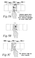
- Figure 4 shows a related of series of 5 figures.
- the brightly colored portion of each figure shows the actual display area of the GUI.
- the display shows the upper most portion of the widget display region 20, and none of the sub-display region (information area 30).
- the user touches the launcher bar 10 and drags his or her finger in a downward direction a portion of the widgets of the widget display region 20 are reduced in size, while the portion of the display that is allocated for the information area 30 is increased.
- the uppermost widget showing the traffic information is now removed from sight, as additionally a greater portion of the information area 30 is shown.
- Widget 1/4 view shows the situation where the user continues to drag his or her finger in a downward direction so that another of the widgets in the widget display region 20 is removed.
- the widget 0/4 view shows a bottom-most position of the GUI, such that none of the widget display region 20 is shown above the launcher bar 10.
- Figure 5 is similar to Figure 4 , although it shows how scrolling can be performed horizontally by flicking ones finger across the display region of the GUI. As shown 5 different panels are present, with only the middle panel being shown in bright colors. An indicator is shown to illustrate which of pages 1-5 is presented while flicking-scrolling horizontally. The indicator highlights the current widget panels so the user has an intuitive feel for where the present panel is located relative to the other panels. As seen, the page 5 panel in the second figure in the series is begun to be shown as the user moves his or her finger towards the right portion Figure 5 . Subsequently, in the last portion of Figure 5 , the full portion of panel 5 is shown. After a predetermined interval time (e.g. 3 second) the indicator turns off and is no longer displayed.
- the panel includes a plurality of widgets relating to a single category.
- FIG. 6 is a flowchart showing how a user interacts with the GUI of Figure 3 .
- the process starts in step S1 where an inquiry is made regarding whether the device receives the user input to side the launcher bar. If the response to the inquiry in step S 1 is negative, the process proceeds to Step S3. However if the response to the inquiry in step S1 is affirmative, the process proceeds to Step S2, where based on the user input, the launch bar is shown to be moved so as to change the display ratio of the widget display region 20 in the information area 30. Subsequently the process proceeds to step S3 where another inquiry is made regarding whether the user input is received for an icon displayed on the launcher bar. If the response to the inquiry is negative, the process returns the Step S1. However if the response to the inquiry in step S3 is affirmative, the process proceeds to Step S4 where displayed information in the information area 30 is changed based on the input received from the user. The process proceeds to Step S 1 unless power is turned off at which the process ends.
- FIG. 7 shows a flowchart illustrating the process of scrolling widget region 20 and information area 30 and selecting applications for apparatus 11.
- apparatus 11 determines if an icon on the launcher bar 10 is selected. If so, apparatus 11 displays the corresponding display information in information area 30 in step S5, and then proceeds to step S6. If not, apparatus 11 skips to step S6 where it determines if the user wishes to vertically scroll one of widget region 20 or information area 30. If so, apparatus 11 changes the display corresponding to widget region 20 or information area 30 in step S7 and then proceeds to step S8. If not, apparatus 11 skips to step S8 where it determines if the user wishes to horizontally scroll one of widget region 20 or information area 30.
- apparatus 11 changes the display corresponding to widget region 20 or information area 30 in step S9 and then proceeds to step S10. If not, apparatus 11 skips to step S10 where it determines if the user has selected a displayed icon. If so, apparatus 11 launches the corresponding application in step S 11 and ends the process. If not, apparatus 11 returns to step S4.
- FIG 8 shows a process for displaying start up information for apparatus 11.
- apparatus 11 determines if it is recovering from sleep mode or it has been turned on. If not, it returns to step S12. If so, apparatus 11 proceeds to step S 13 where it obtains the current time and compares it with a time in the setting information.
- Apparatus 11 determines in step S 14 if the current time is within the setting time range. If so, apparatus 11 displays corresponding display information in widget area 20 in step S 15, and ends the process. If not, apparatus 11 obtains current position information and compares it with the position in the setting information in step S16.
- Apparatus 11 determines in step S 17 if the current position is within the setting position range. If so, apparatus 11 displays corresponding display information in widget area 20 in step S 18, and ends the process. If not, apparatus 11 displays a default widget in step S 19 and ends the process.
- Figure 9 illustrates an embodiment of the present invention including where a main display area is divided into a launcher bar 10 and a widget display area 20 including a plurality of widgets 22.
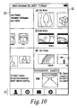
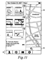
- the content of widget display area 20 can be scrolled horizontally, as shown in Figure 10 to display additional widgets 22. Further, the content of widget display area 20 can also be scrolled horizontally, as shown in Figure 11 , to display a map 24.
- Map 24 includes icons 25 which allow zooming, rotating, and vertically or horizontally dragging the map 24.
- Launcher bar 10 can be scrolled vertically to reveal information display area 30.
- Information display area 30 includes information related to the highlighted icon of launcher bar 10.
- Figure 12 shows information display area 30 containing a plurality of contact information 32 when contact icon 11 of launcher bar 10 is highlighted.
- a contact's phone number can be dialed when the icon including the phone number is clicked on. Further, detailed information regarding a particular contact is displayed when that contact is clicked on, as shown in Figure 13 .
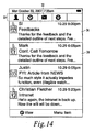
- Figure 14 shows a plurality of the e-mails 34 displayed in the information display area 30 when the e-mail icon 12 of launcher bar 10 is highlighted. The content of each e-mail message is displayed when the e-mail is clicked on, as shown in Figure 15 .
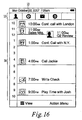
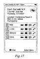
- Figure 16 shows an appointment schedule 36 when clock icon 13 of launcher bar 10 is highlighted. Detailed information regarding a particular appointment is displayed when that appointment is clicked on, as shown in Figure 17 .
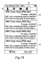
- Figure 18 shows a plurality of webpage thumbnails 38 when globe icon 14 of launcher bar 10 is highlighted.
- the corresponding webpage is displayed when one of the thumbnails 38 is clicked on, as shown in Figure 19 .
- Figure 20 shows a plurality of applications 40 displayed in information display area 30 when application icon 15 of launcher bar 10 is highlighted. Any of the applications 40 can be launched when the corresponding icon is clicked on.
- Figure 9 shows launcher bar 10 at the bottom of the screen such that widget display area 20 takes up most of the main display area.
- Figure 12 shows launcher bar 10 at the top of the screen such that information display area 30 takes up most of the main display area.
- launcher bar 10 may be located at any vertical position in the main display area.
- Figure 21 shows launcher bar 10 near the middle of the main display area with a widget display area 20 above launcher bar 10 and an information display area 30 below launcher bar 10.
- information display area 30 and widget display area 20 may be independently scrolled.
- Figure 22 shows widget display area 20 being horizontally scrolled independent of launcher bar 10 and information display area 30.
- Figure 22 shows information display area 30 being horizontally scrolled independent of launcher bar 10 widget display area 20.
- FIG. 22 it is possible to show a half-displayed widget, as shown in Figure 22 .
- one embodiment moves launcher bar 10 automatically to show an entire widget when the user stops dragging at the middle of the widget. Therefore, the display control unit determines whether or not the half displayed widget should be displayed, and moves launcher bar 10 automatically to show the entire widget based on the displayed ratio of the half displayed widget.
- Figures 9 and 23 do not show half-displayed widgets.
- FIG. 24 illustrates a computer system 1201 upon which an embodiment of the present invention may be implemented.
- the computer system 1201 includes a bus 1202 or other communication mechanism for communicating information, and a processor 1203 coupled with the bus 1202 for processing the information.
- the computer system 1201 also includes a main memory 1204, such as a random access memory (RAM) or other dynamic storage device (e.g., dynamic RAM (DRAM), static RAM (SRAM), and synchronous DRAM (SDRAM)), coupled to the bus 1202 for storing information and instructions to be executed by processor 1203.
- the main memory 1204 may be used for storing temporary variables or other intermediate information during the execution of instructions by the processor 1203.
- the computer system 1201 further includes a read only memory (ROM) 1205 or other static storage device (e.g., programmable ROM (PROM), erasable PROM (EPROM), and electrically erasable PROM (EEPROM)) coupled to the bus 1202 for storing static information and instructions for the processor 1203.
- ROM read only memory
- PROM programmable ROM
- EPROM erasable PROM
- EEPROM electrically erasable PROM
- the computer system 1201 also includes a disk controller 1206 coupled to the bus 1202 to control one or more storage devices for storing information and instructions, such as a magnetic hard disk 1207, and a removable media drive 1208 (e.g., floppy disk drive, read-only compact disc drive, read/write compact disc drive, compact disc jukebox, tape drive, and removable magneto-optical drive).
- a removable media drive 1208 e.g., floppy disk drive, read-only compact disc drive, read/write compact disc drive, compact disc jukebox, tape drive, and removable magneto-optical drive.
- the storage devices may be added to the computer system 1201 using an appropriate device interface (e.g., small computer system interface (SCSI), integrated device electronics (IDE), enhanced-IDE (E-IDE), direct memory access (DMA), or ultra-DMA).
- SCSI small computer system interface
- IDE integrated device electronics
- E-IDE enhanced-IDE
- DMA direct memory access
- ultra-DMA ultra-DMA
- the computer system 1201 may also include special purpose logic devices (e.g., application specific integrated circuits (ASICs)) or configurable logic devices (e.g., simple programmable logic devices (SPLDs), complex programmable logic devices (CPLDs), and field programmable gate arrays (FPGAs)).
- ASICs application specific integrated circuits
- SPLDs simple programmable logic devices
- CPLDs complex programmable logic devices
- FPGAs field programmable gate arrays
- the computer system 1201 may also include a display controller 1209 coupled to the bus 1202 to control a display 1210, such as a LCD or plasma display, for displaying information to a computer user.
- the computer system includes input devices, such as a keyboard 1211 and a pointing device 1212, for interacting with a computer user and providing information to the processor 1203.
- the pointing device 1212 for example, may be a mouse, a trackball, or a pointing stick for communicating direction information and command selections to the processor 1203 and for controlling cursor movement on the display 1210.
- the apparatus 1 When the remote pointing device is used, the apparatus 1, generates a pointer overlaid on the GUI, so the user knows the location of the pointer when choosing to either select an item or "flick" the display to cause a scrolling operation.
- a printer may provide printed listings of data stored and/or generated by the computer system 1201.
- the computer system 1201 performs a portion or all of the processing steps of the invention in response to the processor 1203 executing one or more sequences of one or more instructions contained in a memory, such as the main memory 1204. Such instructions may be read into the main memory 1204 from another computer readable medium, such as a hard disk 1207 or a removable media drive 1208.
- processors in a multi-processing arrangement may also be employed to execute the sequences of instructions contained in main memory 1204.
- hard-wired circuitry may be used in place of or in combination with software instructions. Thus, embodiments are not limited to any specific combination of hardware circuitry and software.
- the computer system 1201 includes at least one computer readable medium or memory for holding instructions programmed according to the teachings of the invention and for containing data structures, tables, records, or other data described herein.
- Examples of computer readable media are compact discs, hard disks, floppy disks, tape, magneto-optical disks, PROMs (EPROM, EEPROM, flash EPROM), DRAM, SRAM, SDRAM, or any other magnetic medium, compact discs (e.g., CD-ROM), or any other optical medium, punch cards, paper tape, or other physical medium with patterns of holes, a carrier wave (described below), or any other medium from which a computer can read.
- the present invention includes software for controlling the computer system 1201, for driving a device or devices for implementing the invention, and for enabling the computer system 1201 to interact with a human user (e.g., print production personnel).
- software may include, but is not limited to, device drivers, operating systems, development tools, and applications software.
- Such computer readable media further includes the computer program product of the present invention for performing all or a portion (if processing is distributed) of the processing performed in implementing the invention.
- the computer code devices of the present invention may be any interpretable or executable code mechanism, including but not limited to scripts, interpretable programs, dynamic link libraries (DLLs), Java classes, and complete executable programs. Moreover, parts of the processing of the present invention may be distributed for better performance, reliability, and/or cost.
- Non-volatile media includes, for example, optical, magnetic disks, and magneto-optical disks, such as the hard disk 1207 or the removable media drive 1208.
- Volatile media includes dynamic memory, such as the main memory 1204.
- Transmission media includes coaxial cables, copper wire and fiber optics, including the wires that make up the bus 1202. Transmission media also may also take the form of acoustic or light waves, such as those generated during radio wave and infrared data communications.
- Various forms of computer readable media may be involved in carrying out one or more sequences of one or more instructions to processor 1203 for execution.
- the instructions may initially be carried on a magnetic disk of a remote computer.
- the remote computer can load the instructions for implementing all or a portion of the present invention remotely into a dynamic memory and send the instructions over a telephone line using a modem.
- a modem local to the computer system 1201 may receive the data on the telephone line and use an infrared transmitter to convert the data to an infrared signal.
- An infrared detector coupled to the bus 1202 can receive the data carried in the infrared signal and place the data on the bus 1202.
- the bus 1202 carries the data to the main memory 1204, from which the processor 1203 retrieves and executes the instructions.
- the instructions received by the main memory 1204 may optionally be stored on storage device 1207 or 1208 either before or after execution by processor 1203.
- the computer system 1201 also includes a communication interface 1213 coupled to the bus 1202.
- the communication interface 1213 provides a two-way data communication coupling to a network link 1214 that is connected to, for example, a local area network (LAN) 1215, or to another communications network 1216 such as the Internet.
- the communication interface 1213 may be a network interface card to attach to any packet switched LAN.
- the communication interface 1213 may be an asymmetrical digital subscriber line (ADSL) card, an integrated services digital network (ISDN) card or a modem to provide a data communication connection to a corresponding type of communications line.
- Wireless links may also be implemented.
- the communication interface 1213 sends and receives electrical, electromagnetic or optical signals that carry digital data streams representing various types of information.
- the network link 1214 typically provides data communication through one or more networks to other data devices.
- the network link 1214 may provide a connection to another computer through a local network 1215 (e.g., a LAN) or through equipment operated by a service provider, which provides communication services through a communications network 1216.
- the local network 1214 and the communications network 1216 use, for example, electrical, electromagnetic, or optical signals that carry digital data streams, and the associated physical layer (e.g., CAT 5 cable, coaxial cable, optical fiber, etc).
- the signals through the various networks and the signals on the network link 1214 and through the communication interface 1213, which carry the digital data to and from the computer system 1201 maybe implemented in baseband signals, or carrier wave based signals.
- the baseband signals convey the digital data as unmodulated electrical pulses that are descriptive of a stream of digital data bits, where the term "bits" is to be construed broadly to mean symbol, where each symbol conveys at least one or more information bits.
- the digital data may also be used to modulate a carrier wave, such as with amplitude, phase and/or frequency shift keyed signals that are propagated over a conductive media, or transmitted as electromagnetic waves through a propagation medium.
- the digital data may be sent as unmodulated baseband data through a "wired" communication channel and/or sent within a predetermined frequency band, different than baseband, by modulating a carrier wave.
- the computer system 1201 can transmit and receive data, including program code, through the network(s) 1215 and 1216, the network link 1214 and the communication interface 1213.
- the network link 1214 may provide a connection through a LAN 1215 to a mobile device 1217 such as a personal digital assistant (PDA) laptop computer, or cellular telephone.
- PDA personal digital assistant
- Figure 25 is a block diagram showing a typical hardware configuration of the information-processing apparatus 11.
- a CPU 101 serving as a control nucleus is connected to a control unit 102 through an FSB (Front Side Bus).
- the control unit 102, other control units and other devices form the processing unit 3 described above.
- the other control units and other devices will be described later.
- the control unit 102 is a component for executing control of a main memory 103 and graphics functions.
- the control unit 102 mainly plays a role for processing a large amount of data at a high speed. In AT compatibility, the control unit 102 is referred to as a north bridge.
- the control unit 102 is connected to the CPU 101, the main memory 103, a control unit 104 and a graphic display unit 105 such as a liquid-crystal display device.
- the control unit 104 is a component mainly for controlling elements such as control devices provided for a user interface and for controlling bus links of devices. In the AT compatibility, the control unit 104 is referred to as a south bridge. In an ISA bridge to the PCI, the control unit 104 plays a role of a bridge between a PCI (Peripheral Component Interconnect) bus and a low-speed bus such as an ISA (Industry Standard Architecture) bus.
- the control unit 104 has the functions of controllers such as an ISA controller and an IDE (Integrated Drive Electronics) controller.
- the PCI bus is connected to a radio LAN (or a W-LAN) serving as a radio communication device 106 and a device 107 for connection with and controlling an external memory and an external apparatus.
- a radio LAN or a W-LAN
- a device 107 for connection with and controlling an external memory and an external apparatus.
- a semiconductor memory device can be employed.
- the device 107 is provided with a control device 108 for reading out and writing data from and into a stick-shaped storage medium and a control device 109 for reading out and writing data from and into a card-shaped storage medium.
- the device 107 has the function of a connection interface with an external apparatus.
- An example of the connection interface is an interface conforming to IEEE 1394 defining specifications of hardware for adding a serial device to a computer.
- the control unit 104 is connected a LAN (Local Area Network) connection device 110 and a USB (Universal Serial Bus) port connected to the touch panel 111 to detect user operation.
- the CPU 101 receives signal of user operation from touch panel 111 and determines such as whether or not user operation is to move the launcher bar or to press an icon on it. If CPU 101 determines that user operation is to move the launcher bar, then CPU 101 changes the display, such as, a ratio of widget display region 20 and information display region 30, or displays corresponding information in information display area based on the user operation. Furthermore, CPU 101 determines whether vertical scrolling or horizontal scrolling is selected, or compares the current time or current position information with time or position information in setting information based on the program stored on storage unit 116. These processes are described hereafter.
- An auxiliary storage unit 112 is a drive for driving a disk such as a magnetic or optical disk.
- the auxiliary storage unit 112 is a drive for driving a large-capacity storage medium such as a hard disk.
- the auxiliary storage unit 112 is connected to the control unit 104, which serves as an internal IDE controller.
- An audio codec 113 connected to the control unit 104 is a component for outputting an audio signal obtained as a result of a digital-analog conversion process to a component such as a speaker 114 or head phones 115.
- the audio signal represents a voice or a sound.
- the audio codec 113 carries out a process to convert audio input data into a digital one.
- a storage unit 116 is a memory for storing a control program for driving a computer.
- the storage unit 116 is connected to the control unit 104 and a control unit 117 by using an LPC (Low Pin Count) bus or the like.
- LPC Low Pin Count
- the control unit 117 is a general-purpose unit for controlling a variety of signals. As the control unit 117, for example, an EC (Embedded Controller) is employed. The control unit 117 also controls the power supply of the information-processing apparatus 11 and additional functions of the information-processing apparatus 11. In the case of a portable information-processing apparatus, the control unit 117 is a microcomputer. It is to be noted that, by modifying a control program stored in the storage unit 116, the method for controlling the computer can be changed.
- EC embedded Controller
- An operation section 118 including the operation element 17 provided on the main body of the information-processing apparatus 11 outputs a signal to the control unit 117.
- a connection section 119 for connecting an external apparatus to the information-processing apparatus 11 a USB connector is provided on the main body of the information-processing apparatus 11. The USB connector 119 is also connected to the control unit 104.
- a power-supply section not shown in the figure receives a commercial power-supply voltage from an AC adaptor.
- the information-processing apparatus 11 may be powered by a battery pack serving as DC power supply.
- the battery pack includes secondary batteries or fuel batteries.
Abstract
Description
- This application claims priority under 35 U.S.C. §119(e) to
U.S. Provisional Application No. 60/991,013, filed November 29, 2007 - The present invention relates to fixed or portable computing devices including graphical user interfaces. More particularly, the present invention relates to graphical user interfaces involving sub-dividable display regions that enable a user to navigate independently within the sub-dividable display regions.
- Computer systems conventionally use a graphical user interface (GUI) that allows for the display of various types of information. Some systems, such as MICROSOFT WINDOWS uses a desktop metaphor one which different icons are arranged, which allow a user to "point and click" on different icons to execute an application.
- Example applications include word processing programs, web browsers, etc. The various icons may be selected by a user who selects different particular icons with through input from various computer input devices.
- Some graphical user interfaces include touch panel displays that allow for the execution of certain applications, as a substitute for using a peripheral or built-in pointing device.
- The present inventors recognize that conventional GUIs do not allow for the divisibility of the display region into separately "scrollable" display regions. The present inventors recognized that there is a logical connection of how information is presented to a user in a spatial context. However, conventional graphical user interfaces fail to take advantage of a human's memory to maintain a mental persistence of previously viewed material as it related to presently viewed material.
- In a non-limiting example, the present invention allows for the division of a display area into multiple subdisplay regions by use of a launcher bar. Within one of the subregions, either above or below the launcher bar, additional information is displayed in logical arranged categories. Some of the categories of information, such as weather information is presented on the subdisplay region, but if the user scrolls in the subdisplay region to one side or the other, the user will be presented with the weather forecast for the next day, or the weather from the past days is subsequently presented to the user when the scroll is performed by "flicking" of the screen.
- The graphical user interface of the present invention may be implemented in any one of a number of different computer-based devices. In one example the graphical user interface is implemented on a SmartPhone, that includes wireless connectivity features. However the invention is not so limited, as it may also be implemented in a number of other wired and wireless computer-based applications, including desktop or mobile computers, navigation systems, menu panels and touchscreens installed in automobiles, etc.
-
-
Figure 1 is a perspective view of a SmartPhone embodiment of a computing device that uses a GUI according to the present invention. -
Figure 2 shows another prospective view of the information processing apparatus ofFigure 1 . -
Figure 3 is a graphical user interface that helps illustrate the different terminology used herein. -
Figure 4 shows a succession of different views for how scrolling may be achieved through the "flick" of one's finger across a screen in a vertical direction. -
Figure 5 shows another succession of views showing how the screen may be scrolled horizontally through a flicking of the screen. -
Figure 6 is a flowchart showing a process flow of how either a vertical or horizontal scrolling operation is performed according to the present invention. -
Figure 7 is a flow chart showing the process of scrolling widget region and information area. -
Figure 8 is a flowchart showing the process of displaying start up information. -
Figure 9 is a screenshot showing a launcher bar and a widget display area of the present invention. -
Figure 10 is a screenshot showing horizontally scrolled widgets of the present invention. -
Figure 11 is a screenshot showing a map display. -
Figure 12 is a screenshot showing a display of multiple contacts. -
Figure 13 a screenshot showing detailed information on a single contact. -
Figure 14 is a screenshot showing a display of multiple e-mails. -
Figure 15 is a screenshot showing a single e-mail. -
Figure 16 is a screenshot showing an appointment schedule. -
Figure 17 is a screenshot showing detailed information on a single appointment. -
Figure 18 is a screenshot showing multiple webpage thumbnails. -
Figure 19 is a screenshot showing detailed information on a single webpage. -
Figure 20 is a screenshot showing a plurality of applications. -
Figure 21 is a screenshot showing the launcher bar near the middle of the display. -
Figure 22 is a screenshot showing horizontal scrolling all of the widgets. -
Figure 23 is a screenshot showing horizontal scrolling of the information area. -
Figure 24 is a block diagram showing a typical hardware configuration of the information-processing apparatus 11. -
Figure 25 is a block diagram showing different hardware and/or software components that may be used to implement the present invention. - Referring now to the drawings, wherein like reference numerals designate identical or corresponding parts throughout the several views.
-
Figure 1 shows a perspective view of asmart phone 1 according one embodiment of the present invention. The smart phone 1 (or information processing apparatus) includes abase unit 2 that host thereon anintermediate body 3 that is covered by acover body 4. Hosted on thecover body 4 is a display unit 21A that displays the GUI shown onFigure 3 . On theintermediate body 3 are included a set ofinput keys 20 and 20A for inputting data into theinformation processing apparatus 1. Theinformation processing apparatus 1 includes a GPS receiver, as well as wireless communication capability for communicating over mobile networks. Although not shown, electrical interfaces are included that allow for the exchange of information from theinformation processing apparatus 1 to auxiliary devices and/or a network. Such example interfaces includes USB, HDMI, IEEE 1291, etc. - The display unit 21A includes a touch screen that enables a user to have his or her selection recognized by the display unit 21A when touching the display unit 21A with his or her figure, or other pointing instrument. Alternatively, the
information display apparatus 1 may allow for a user to use a remote pointing device, either wired or wirelessly connected to theinformation processing apparatus 1. The remote pointing devices enables the user to perform scrolling apparitions and execution of applications, by pointing and selecting different widgets, or information items that would otherwise be selected or scrolled by using the touching of ones finger on the touch panel of display unit 21 A. - The wireless connection can be made with infrared, or RF remote capability, such as using a Bluetooth interface. A wired remote control head may also be used that would allow for the user to hold the remote pointing device in the users hand when used. Alternatively, the device could be built into a convenient location such as the steering wheel of an automobile. The remote pointing device would allow the user to visually observe the GUI on a display screen, such as a screen mounted on a car's dashboard, but would avoid the need for the user to reach over and make physical contact with the screen in order to input a selection or navigate in the GUI. Because the user can operate the GUI without having to extend his arm and reach the screen on the dashboard, it is much safer to operate the car during normal operations.
- The
information processing apparatus 1 includes a wireless capability, such as Bluetooth, that allows for the pairing of theinformation processing apparatus 1 to other accessible monitors. For example in the context of an automobile, theapparatus 1 is capable of providing a Bluetooth connectivity to the display panel such that the GUI ofFigure 3 is visible on the dashboard display panel. Information contained in theinformation processing apparatus 1, or the accessibility to other network information through theinformation processing apparatus 1, is made available for display on the dashboard display panel by way of the Bluetooth connection. The present inventors have recognized that this can be a much safer way to operate different navigation systems or other computer based display and input system when driving ones automobile. -
Figure 2 shows another perspective view of theinformation processing apparatus 1, although thecover body 4 is made to cover thebase unit 2. Moreover, theinformation processing apparatus 1 inFigure 2 as shown to be in a closed position. Because theapparatus 1 has a mobile telephone capability, the user is able to use the apparatus as a cellular telephone, as well as for other functions, such as a MP3 player, camera, web browser, etc. -
Figure 3 shows a main display region of a GUI displayed on a display, such as a LCD, plasma, CRT, LED or other type of unit capable of visually presenting computer-produced imagines of text and/or graphics. The main display region may be implemented as a touch panel that allows for human interaction with the main display region. However, in another embodiment, a touch panel is not required and the interaction with the GUI may be implemented through a pointing device for remote operation that does not require touching of the main display region itself. Example pointing devices include a mouse, trackball, jog-dial, touchpad, sensor pad, etc., each adapted to allow a human to interact with the pointing device so as to select and or scroll/"flick" content displayed on the display. The pointing device need not require tactile input, but rather may also allow for pointing/scrolling/selection to be done by way of eye movement detection by having an integrated or peripheral eye movement detection device. The eye movement detection device is particularly helpful in the context of using the display in an automotive setting, where it is safer for the driver to keep both of his hands on the steering wheel, while visually interacting with the GUI displayed on the display device. - However in the present example, in
Figure 3 the main display region is displayed on a touch panel display and the main display region is separated into a widget display region 20 (sometimes referred to as "sub-display region"), launcher bar 10 (sometimes referred to as "dividing region"), and information area 30 (sometimes referred to as "sub-display region"). Within the main display region, thelauncher bar 10 separates thewidget display area 20 from theinformation area 30. The launcher bar is movable through a dragging operation (in this embodiment the user drags his finger from on top of the launcher bar to another location) so as to change the ratio of thewidget display region 20 and theinformation area 30. In particular, in the present touch screen embodiment, thelauncher bar region 10 may be moved upwards by the user touching one of theicons launcher bar 10 following the user's finger in an upwards direction so as to reduce the size of thewidget display region 20, and increase the size of theinformation area 30. - Each of the icons 10-15 are described in a different section that follows. However each of the icons 10-15 represents a different function such that when touched, displays information associated with the icon, or launches an application associated with that particular icon, such as an e-mail operation. In the
widget display region 20, a particular widget, 22, which is shown to be a weather graphic, is displayed in combination with other widgets in thewidget display region 20. - Within either of the
widget display region 20, and/orinformation area 30, the user has the option for scrolling either vertically or horizontally. The scrolling operation is performed by "flicking" the screen, which is executed by the user dragging his finger across the screen (see e.g.,Figures 4 and5 ). For example, when the user places his or her finger on thewidget 22 and then flicks the user's finger in an upward or downward direction within either thewidget display region 20, or theinformation area 30, the newly displayed information is a same kind of information (e.g., same category of information). In one example, the same kind of information is a next day in a schedule, or a next contact person of a list of contact persons. On the other hand, when the display is flicked either to the right side or to the left side, the display is changed to show a different kind of information. In this way, the operator recognizes with the operator's own memory (i.e., what the user remembers or what the user can intuitively imagine will appear) the relationship between scrolling up or down so as to stay within a particular category, or scrolling to the right or left in order to change the type of information. - For example with respect to the
widget display region 20, aregion 22 is one of a plurality of different widgets that is displayed. When displayed as a widget, typically a "small" application that does not require a significant amount of memory (such as a listing of movies, music, weather information, stock market information, travel information, navigation information) is displayed in thewidget display region 20. The display information is displayed as part of setting information such as a number, kind, size, position information of the widget. Further, in one embodiment, when a widget is selected, a webpage which includes detailed information regarding the widget is displayed. - There are several types of setting information, mostly related to time and/or position. The apparatus that displays the GUI of
Figure 3 is able to read the time setting information (e.g., a previously saved time, set the a user, or set as a default value based on a time zone that the unit can recognize based on position information from a built in, or remote, GPS function) and compare the present time and/or position information with the current time or position. The apparatus is then able to decide which widget should be displayed automatically. As an example, early in the morning, the user may choose to have weather information, time information, and traffic information displayed. However at a later time during the day, the information may switch to something that is more useful for that particular user at that particular time of day, such as access to a word processing program, spreadsheet program, e-mail, etc. In the evening, the user may choose to have displayed topical information such as sports information, etc., that is of particular interest to that user. - The underlying device that hosts the GUI includes a GPS data reception function. As discussed above, the apparatus having the display may include the GPS receiver or the location information may be provided remotely, or input via user entry into the device. Nevertheless, by understanding its present position, the device may connect to a network, either wired or wirelessly, to obtain information related to that particular location. Such information may be traffic information, weather information, time information including time zone, etc.
- The
information area 30, which inFigure 3 is displayed underneath the launcher bar, includes various information such as contact list, mailbox, the individual's schedule, or an RSS reader, or a menu selection display for selecting other types of displays. The selection of different icons is made by clicking or touching one of the icons (or tabs) displayed on the launcher bar or flicking the display to the right or left so as to obtain other icons for execution. - When the user scrolls either up or down inside of the upper side region, the display information is scrolled in units of the widget. Therefore, if in the scrolling operation, only a portion of the widget is displayed, the system will continue to move that widget until either all of it or none of it is displayed. Further, the user may slide (or drag) the launcher bar so as to display information that is scrolled in units of the widget.
- In one example, when a user gets new mail, the
launcher bar 10 moves up automatically and shows a greater portion of theinformation area 30 so that the mail may be displayed. The user will then be able to recognize the abstract or subject line of the mail, thus allowing the user to recognize the existence of such mail as soon as possible. - The user may also stop the changing of the display information in the middle of scrolling to the left or right so that the apparatus displays larger information automatically.
-
Figure 4 shows a related of series of 5 figures. The brightly colored portion of each figure shows the actual display area of the GUI. Inwidget 4/4 view, the display shows the upper most portion of thewidget display region 20, and none of the sub-display region (information area 30). However as the user touches thelauncher bar 10 and drags his or her finger in a downward direction, a portion of the widgets of thewidget display region 20 are reduced in size, while the portion of the display that is allocated for theinformation area 30 is increased. As shown inwidget 2/4 view, the uppermost widget showing the traffic information is now removed from sight, as additionally a greater portion of theinformation area 30 is shown.Widget 1/4 view shows the situation where the user continues to drag his or her finger in a downward direction so that another of the widgets in thewidget display region 20 is removed. Finally, the widget 0/4 view shows a bottom-most position of the GUI, such that none of thewidget display region 20 is shown above thelauncher bar 10. - Nevertheless, as can be imagined based on the organization of the series of figures shown in
Figure 4 , the user nevertheless will be able to remember the previous locations of the widgets in thewidget display region 20. Therefore, it is relatively straight forward and easy for the user to remember how to navigate back to thewidget display region 20, and the particular widgets that were of interest to that user. -
Figure 5 is similar toFigure 4 , although it shows how scrolling can be performed horizontally by flicking ones finger across the display region of the GUI. As shown 5 different panels are present, with only the middle panel being shown in bright colors. An indicator is shown to illustrate which of pages 1-5 is presented while flicking-scrolling horizontally. The indicator highlights the current widget panels so the user has an intuitive feel for where the present panel is located relative to the other panels. As seen, thepage 5 panel in the second figure in the series is begun to be shown as the user moves his or her finger towards the right portionFigure 5 . Subsequently, in the last portion ofFigure 5 , the full portion ofpanel 5 is shown. After a predetermined interval time (e.g. 3 second) the indicator turns off and is no longer displayed. In one embodiment, the panel includes a plurality of widgets relating to a single category. -
Figure 6 is a flowchart showing how a user interacts with the GUI ofFigure 3 . The process starts in step S1 where an inquiry is made regarding whether the device receives the user input to side the launcher bar. If the response to the inquiry instep S 1 is negative, the process proceeds to Step S3. However if the response to the inquiry in step S1 is affirmative, the process proceeds to Step S2, where based on the user input, the launch bar is shown to be moved so as to change the display ratio of thewidget display region 20 in theinformation area 30. Subsequently the process proceeds to step S3 where another inquiry is made regarding whether the user input is received for an icon displayed on the launcher bar. If the response to the inquiry is negative, the process returns the Step S1. However if the response to the inquiry in step S3 is affirmative, the process proceeds to Step S4 where displayed information in theinformation area 30 is changed based on the input received from the user. The process proceeds to StepS 1 unless power is turned off at which the process ends. -
Figure 7 shows a flowchart illustrating the process of scrollingwidget region 20 andinformation area 30 and selecting applications forapparatus 11. In step S4,apparatus 11 determines if an icon on thelauncher bar 10 is selected. If so,apparatus 11 displays the corresponding display information ininformation area 30 in step S5, and then proceeds to step S6. If not,apparatus 11 skips to step S6 where it determines if the user wishes to vertically scroll one ofwidget region 20 orinformation area 30. If so,apparatus 11 changes the display corresponding towidget region 20 orinformation area 30 in step S7 and then proceeds to step S8. If not,apparatus 11 skips to step S8 where it determines if the user wishes to horizontally scroll one ofwidget region 20 orinformation area 30. If so,apparatus 11 changes the display corresponding towidget region 20 orinformation area 30 in step S9 and then proceeds to step S10. If not,apparatus 11 skips to step S10 where it determines if the user has selected a displayed icon. If so,apparatus 11 launches the corresponding application in step S 11 and ends the process. If not,apparatus 11 returns to step S4. -
Figure 8 shows a process for displaying start up information forapparatus 11. In step S12,apparatus 11 determines if it is recovering from sleep mode or it has been turned on. If not, it returns to step S12. If so,apparatus 11 proceeds to stepS 13 where it obtains the current time and compares it with a time in the setting information.Apparatus 11 determines in step S 14 if the current time is within the setting time range. If so,apparatus 11 displays corresponding display information inwidget area 20 instep S 15, and ends the process. If not,apparatus 11 obtains current position information and compares it with the position in the setting information in step S16.Apparatus 11 determines in step S 17 if the current position is within the setting position range. If so,apparatus 11 displays corresponding display information inwidget area 20 instep S 18, and ends the process. If not,apparatus 11 displays a default widget in step S 19 and ends the process. -
Figure 9 illustrates an embodiment of the present invention including where a main display area is divided into alauncher bar 10 and awidget display area 20 including a plurality ofwidgets 22. The content ofwidget display area 20 can be scrolled horizontally, as shown inFigure 10 to displayadditional widgets 22. Further, the content ofwidget display area 20 can also be scrolled horizontally, as shown inFigure 11 , to display amap 24.Map 24 includesicons 25 which allow zooming, rotating, and vertically or horizontally dragging themap 24. -
Launcher bar 10 can be scrolled vertically to revealinformation display area 30.Information display area 30 includes information related to the highlighted icon oflauncher bar 10. For example,Figure 12 showsinformation display area 30 containing a plurality ofcontact information 32 whencontact icon 11 oflauncher bar 10 is highlighted. In an embodiment where the apparatus includes a phone function, a contact's phone number can be dialed when the icon including the phone number is clicked on. Further, detailed information regarding a particular contact is displayed when that contact is clicked on, as shown inFigure 13 . -
Figure 14 shows a plurality of thee-mails 34 displayed in theinformation display area 30 when thee-mail icon 12 oflauncher bar 10 is highlighted. The content of each e-mail message is displayed when the e-mail is clicked on, as shown inFigure 15 . -
Figure 16 shows anappointment schedule 36 whenclock icon 13 oflauncher bar 10 is highlighted. Detailed information regarding a particular appointment is displayed when that appointment is clicked on, as shown inFigure 17 . -
Figure 18 shows a plurality ofwebpage thumbnails 38 whenglobe icon 14 oflauncher bar 10 is highlighted. The corresponding webpage is displayed when one of thethumbnails 38 is clicked on, as shown inFigure 19 . -
Figure 20 shows a plurality ofapplications 40 displayed ininformation display area 30 whenapplication icon 15 oflauncher bar 10 is highlighted. Any of theapplications 40 can be launched when the corresponding icon is clicked on. - When moving
launcher bar 10 vertically, the relative sizes of thewidget display area 20 in theinformation display area 30 are changed. For example,Figure 9 showslauncher bar 10 at the bottom of the screen such thatwidget display area 20 takes up most of the main display area.Figure 12 showslauncher bar 10 at the top of the screen such thatinformation display area 30 takes up most of the main display area. However,launcher bar 10 may be located at any vertical position in the main display area. For example,Figure 21 showslauncher bar 10 near the middle of the main display area with awidget display area 20 abovelauncher bar 10 and aninformation display area 30 belowlauncher bar 10. Further,information display area 30 andwidget display area 20 may be independently scrolled. For example,Figure 22 showswidget display area 20 being horizontally scrolled independent oflauncher bar 10 andinformation display area 30.Figure 22 showsinformation display area 30 being horizontally scrolled independent oflauncher bar 10widget display area 20. - In one embodiment, it is possible to show a half-displayed widget, as shown in
Figure 22 . However, one embodiment moveslauncher bar 10 automatically to show an entire widget when the user stops dragging at the middle of the widget. Therefore, the display control unit determines whether or not the half displayed widget should be displayed, and moveslauncher bar 10 automatically to show the entire widget based on the displayed ratio of the half displayed widget. Thus,Figures 9 and23 do not show half-displayed widgets. -
Figure 24 illustrates acomputer system 1201 upon which an embodiment of the present invention may be implemented. Thecomputer system 1201 includes abus 1202 or other communication mechanism for communicating information, and aprocessor 1203 coupled with thebus 1202 for processing the information. Thecomputer system 1201 also includes amain memory 1204, such as a random access memory (RAM) or other dynamic storage device (e.g., dynamic RAM (DRAM), static RAM (SRAM), and synchronous DRAM (SDRAM)), coupled to thebus 1202 for storing information and instructions to be executed byprocessor 1203. In addition, themain memory 1204 may be used for storing temporary variables or other intermediate information during the execution of instructions by theprocessor 1203. Thecomputer system 1201 further includes a read only memory (ROM) 1205 or other static storage device (e.g., programmable ROM (PROM), erasable PROM (EPROM), and electrically erasable PROM (EEPROM)) coupled to thebus 1202 for storing static information and instructions for theprocessor 1203. - The
computer system 1201 also includes adisk controller 1206 coupled to thebus 1202 to control one or more storage devices for storing information and instructions, such as a magnetichard disk 1207, and a removable media drive 1208 (e.g., floppy disk drive, read-only compact disc drive, read/write compact disc drive, compact disc jukebox, tape drive, and removable magneto-optical drive). The storage devices may be added to thecomputer system 1201 using an appropriate device interface (e.g., small computer system interface (SCSI), integrated device electronics (IDE), enhanced-IDE (E-IDE), direct memory access (DMA), or ultra-DMA). - The
computer system 1201 may also include special purpose logic devices (e.g., application specific integrated circuits (ASICs)) or configurable logic devices (e.g., simple programmable logic devices (SPLDs), complex programmable logic devices (CPLDs), and field programmable gate arrays (FPGAs)). - The
computer system 1201 may also include adisplay controller 1209 coupled to thebus 1202 to control adisplay 1210, such as a LCD or plasma display, for displaying information to a computer user. The computer system includes input devices, such as akeyboard 1211 and apointing device 1212, for interacting with a computer user and providing information to theprocessor 1203. Thepointing device 1212, for example, may be a mouse, a trackball, or a pointing stick for communicating direction information and command selections to theprocessor 1203 and for controlling cursor movement on thedisplay 1210. When the remote pointing device is used, theapparatus 1, generates a pointer overlaid on the GUI, so the user knows the location of the pointer when choosing to either select an item or "flick" the display to cause a scrolling operation. In addition, a printer may provide printed listings of data stored and/or generated by thecomputer system 1201. - The
computer system 1201 performs a portion or all of the processing steps of the invention in response to theprocessor 1203 executing one or more sequences of one or more instructions contained in a memory, such as themain memory 1204. Such instructions may be read into themain memory 1204 from another computer readable medium, such as ahard disk 1207 or aremovable media drive 1208. One or more processors in a multi-processing arrangement may also be employed to execute the sequences of instructions contained inmain memory 1204. In alternative embodiments, hard-wired circuitry may be used in place of or in combination with software instructions. Thus, embodiments are not limited to any specific combination of hardware circuitry and software. - As stated above, the
computer system 1201 includes at least one computer readable medium or memory for holding instructions programmed according to the teachings of the invention and for containing data structures, tables, records, or other data described herein. Examples of computer readable media are compact discs, hard disks, floppy disks, tape, magneto-optical disks, PROMs (EPROM, EEPROM, flash EPROM), DRAM, SRAM, SDRAM, or any other magnetic medium, compact discs (e.g., CD-ROM), or any other optical medium, punch cards, paper tape, or other physical medium with patterns of holes, a carrier wave (described below), or any other medium from which a computer can read. - Stored on any one or on a combination of computer readable media, the present invention includes software for controlling the
computer system 1201, for driving a device or devices for implementing the invention, and for enabling thecomputer system 1201 to interact with a human user (e.g., print production personnel). Such software may include, but is not limited to, device drivers, operating systems, development tools, and applications software. Such computer readable media further includes the computer program product of the present invention for performing all or a portion (if processing is distributed) of the processing performed in implementing the invention. - The computer code devices of the present invention may be any interpretable or executable code mechanism, including but not limited to scripts, interpretable programs, dynamic link libraries (DLLs), Java classes, and complete executable programs. Moreover, parts of the processing of the present invention may be distributed for better performance, reliability, and/or cost.
- The term "computer readable medium" as used herein refers to any medium that participates in providing instructions to the
processor 1203 for execution. A computer readable medium may take many forms, including but not limited to, non-volatile media, volatile media, and transmission media. Non-volatile media includes, for example, optical, magnetic disks, and magneto-optical disks, such as thehard disk 1207 or the removable media drive 1208. Volatile media includes dynamic memory, such as themain memory 1204. Transmission media includes coaxial cables, copper wire and fiber optics, including the wires that make up thebus 1202. Transmission media also may also take the form of acoustic or light waves, such as those generated during radio wave and infrared data communications. - Various forms of computer readable media may be involved in carrying out one or more sequences of one or more instructions to
processor 1203 for execution. For example, the instructions may initially be carried on a magnetic disk of a remote computer. The remote computer can load the instructions for implementing all or a portion of the present invention remotely into a dynamic memory and send the instructions over a telephone line using a modem. A modem local to thecomputer system 1201 may receive the data on the telephone line and use an infrared transmitter to convert the data to an infrared signal. An infrared detector coupled to thebus 1202 can receive the data carried in the infrared signal and place the data on thebus 1202. Thebus 1202 carries the data to themain memory 1204, from which theprocessor 1203 retrieves and executes the instructions. The instructions received by themain memory 1204 may optionally be stored onstorage device processor 1203. - The
computer system 1201 also includes acommunication interface 1213 coupled to thebus 1202. Thecommunication interface 1213 provides a two-way data communication coupling to anetwork link 1214 that is connected to, for example, a local area network (LAN) 1215, or to anothercommunications network 1216 such as the Internet. For example, thecommunication interface 1213 may be a network interface card to attach to any packet switched LAN. As another example, thecommunication interface 1213 may be an asymmetrical digital subscriber line (ADSL) card, an integrated services digital network (ISDN) card or a modem to provide a data communication connection to a corresponding type of communications line. Wireless links may also be implemented. In any such implementation, thecommunication interface 1213 sends and receives electrical, electromagnetic or optical signals that carry digital data streams representing various types of information. - The
network link 1214 typically provides data communication through one or more networks to other data devices. For example, thenetwork link 1214 may provide a connection to another computer through a local network 1215 (e.g., a LAN) or through equipment operated by a service provider, which provides communication services through acommunications network 1216. Thelocal network 1214 and thecommunications network 1216 use, for example, electrical, electromagnetic, or optical signals that carry digital data streams, and the associated physical layer (e.g.,CAT 5 cable, coaxial cable, optical fiber, etc). The signals through the various networks and the signals on thenetwork link 1214 and through thecommunication interface 1213, which carry the digital data to and from thecomputer system 1201 maybe implemented in baseband signals, or carrier wave based signals. The baseband signals convey the digital data as unmodulated electrical pulses that are descriptive of a stream of digital data bits, where the term "bits" is to be construed broadly to mean symbol, where each symbol conveys at least one or more information bits. The digital data may also be used to modulate a carrier wave, such as with amplitude, phase and/or frequency shift keyed signals that are propagated over a conductive media, or transmitted as electromagnetic waves through a propagation medium. Thus, the digital data may be sent as unmodulated baseband data through a "wired" communication channel and/or sent within a predetermined frequency band, different than baseband, by modulating a carrier wave. Thecomputer system 1201 can transmit and receive data, including program code, through the network(s) 1215 and 1216, thenetwork link 1214 and thecommunication interface 1213. Moreover, thenetwork link 1214 may provide a connection through aLAN 1215 to amobile device 1217 such as a personal digital assistant (PDA) laptop computer, or cellular telephone. -
Figure 25 is a block diagram showing a typical hardware configuration of the information-processingapparatus 11. - As shown in the figure, a
CPU 101 serving as a control nucleus is connected to acontrol unit 102 through an FSB (Front Side Bus). Thecontrol unit 102, other control units and other devices form theprocessing unit 3 described above. The other control units and other devices will be described later. Thecontrol unit 102 is a component for executing control of amain memory 103 and graphics functions. Thecontrol unit 102 mainly plays a role for processing a large amount of data at a high speed. In AT compatibility, thecontrol unit 102 is referred to as a north bridge. In this embodiment, thecontrol unit 102 is connected to theCPU 101, themain memory 103, acontrol unit 104 and agraphic display unit 105 such as a liquid-crystal display device. - The
control unit 104 is a component mainly for controlling elements such as control devices provided for a user interface and for controlling bus links of devices. In the AT compatibility, thecontrol unit 104 is referred to as a south bridge. In an ISA bridge to the PCI, thecontrol unit 104 plays a role of a bridge between a PCI (Peripheral Component Interconnect) bus and a low-speed bus such as an ISA (Industry Standard Architecture) bus. Thecontrol unit 104 has the functions of controllers such as an ISA controller and an IDE (Integrated Drive Electronics) controller. - The PCI bus is connected to a radio LAN (or a W-LAN) serving as a
radio communication device 106 and adevice 107 for connection with and controlling an external memory and an external apparatus. As the external memory, a semiconductor memory device can be employed. Thedevice 107 is provided with acontrol device 108 for reading out and writing data from and into a stick-shaped storage medium and acontrol device 109 for reading out and writing data from and into a card-shaped storage medium. In addition, thedevice 107 has the function of a connection interface with an external apparatus. An example of the connection interface is an interface conforming to IEEE 1394 defining specifications of hardware for adding a serial device to a computer. - The
control unit 104 is connected a LAN (Local Area Network)connection device 110 and a USB (Universal Serial Bus) port connected to thetouch panel 111 to detect user operation. TheCPU 101 receives signal of user operation fromtouch panel 111 and determines such as whether or not user operation is to move the launcher bar or to press an icon on it. IfCPU 101 determines that user operation is to move the launcher bar, thenCPU 101 changes the display, such as, a ratio ofwidget display region 20 andinformation display region 30, or displays corresponding information in information display area based on the user operation. Furthermore,CPU 101 determines whether vertical scrolling or horizontal scrolling is selected, or compares the current time or current position information with time or position information in setting information based on the program stored onstorage unit 116. These processes are described hereafter. - An
auxiliary storage unit 112 is a drive for driving a disk such as a magnetic or optical disk. In this embodiment, theauxiliary storage unit 112 is a drive for driving a large-capacity storage medium such as a hard disk. Theauxiliary storage unit 112 is connected to thecontrol unit 104, which serves as an internal IDE controller. - An
audio codec 113 connected to thecontrol unit 104 is a component for outputting an audio signal obtained as a result of a digital-analog conversion process to a component such as aspeaker 114 orhead phones 115. The audio signal represents a voice or a sound. In an apparatus configuration including a microphone, theaudio codec 113 carries out a process to convert audio input data into a digital one. - A
storage unit 116 is a memory for storing a control program for driving a computer. Thestorage unit 116 is connected to thecontrol unit 104 and acontrol unit 117 by using an LPC (Low Pin Count) bus or the like. - The
control unit 117 is a general-purpose unit for controlling a variety of signals. As thecontrol unit 117, for example, an EC (Embedded Controller) is employed. Thecontrol unit 117 also controls the power supply of the information-processingapparatus 11 and additional functions of the information-processingapparatus 11. In the case of a portable information-processing apparatus, thecontrol unit 117 is a microcomputer. It is to be noted that, by modifying a control program stored in thestorage unit 116, the method for controlling the computer can be changed. - An
operation section 118 including theoperation element 17 provided on the main body of the information-processingapparatus 11 outputs a signal to thecontrol unit 117. As aconnection section 119 for connecting an external apparatus to the information-processingapparatus 11, a USB connector is provided on the main body of the information-processingapparatus 11. TheUSB connector 119 is also connected to thecontrol unit 104. - It is to be noted that a power-supply section not shown in the figure receives a commercial power-supply voltage from an AC adaptor. As an alternative, the information-processing
apparatus 11 may be powered by a battery pack serving as DC power supply. Typically, the battery pack includes secondary batteries or fuel batteries. - Obviously, numerous modifications and variations of the present invention are possible in light of the above teachings. It is therefore to be understood that within the scope of the appended claims, the invention may be practiced otherwise than as specifically described herein.
Claims (8)
- An information processing apparatus comprising:a display unit configured to display a dividing region dividing a main display region into two sub regions; anda control unit configured to control said display unitto display a plurality of icons in said dividing region,to change position of said dividing region in said main display region based on user input,to display, when an icon of said plurality of icons is selected, information corresponding to said icon in at least one of the sub regions.
- An information processing apparatus according to claim 1 further comprising:a detector configured to detect a gesture of a user with respect to said main display region,wherein said control unit is configured to control said display unit to change information in said sub region based on said gesture.
- An information processing apparatus according to claim 1 or 2, wherein said control unit is configured to control said display unit to display widget information including a plurality of widgets in one sub region of said two sub regions.
- An information processing apparatus according to claim 1, 2 or 3, wherein said control unit is configured to control the display unit to display the plurality of widgets selected based on user input.
- An information processing apparatus according to one of the claims 1 to 4, wherein said control unit is configured to define a plurality of said widget information and said display unit is configured to display one widget information of said plurality of widget information in one sub region.
- An information processing apparatus according to claim 5, wherein said control unit is configured to control the display unit to display other widget information as a substitute for said one widget information when said detector is configured to detect a flick gesture by the user with respect to said one sub region.
- An information processing apparatus according to claim 5 or 6, wherein said display unit is configured to display a plurality of buttons, each button corresponding to one widget information, and said control unit is configured to control, when said detector detects that one button is selected, the display unit to display other widget information corresponding to said selected button, as a substitute for said one widget information.
- An information processing apparatus according to claim 5, 6 or 7, further comprising;an acquisition unit configured to acquire current parameter information,
wherein said control unit is configured to select said one widget information based on comparison result of said current parameter information and a plurality of predetermined parameter information which each correspond to a plurality of predetermined widget information.9. An information processing apparatus according to claim 8, wherein said parameter information is time information and/or location information.10. An information processing apparatus according to one of the claims 1 to 9,
wherein said control unit is configured to control the display unit to display one fixed information of a plurality of setting disable fixed information in an other sub region.11. An information processing apparatus according to claim 10, wherein said plurality of icons represents a plurality of fixed information displayed in said sub region.12. An information processing apparatus according to claim 10 or 11, wherein said control unit is configured to move said dividing region to the top of said main display region and to display said one fixed information based on the detection of selection of the icon when said display unit displays said dividing region in the bottom of said main display region.13. An information processing apparatus according to claim 10, 11 or 12, wherein said control unit is configured to control the display unit to display other fixed information as a substitute for said one fixed information based on the detection of a flick gesture by said user in said other sub region detected by said detector.
Applications Claiming Priority (2)
| Application Number | Priority Date | Filing Date | Title |
|---|---|---|---|
| US99101307P | 2007-11-29 | 2007-11-29 | |
| US12/242,279 US8245155B2 (en) | 2007-11-29 | 2008-09-30 | Computer implemented display, graphical user interface, design and method including scrolling features |
Publications (2)
| Publication Number | Publication Date |
|---|---|
| EP2068236A1 true EP2068236A1 (en) | 2009-06-10 |
| EP2068236B1 EP2068236B1 (en) | 2017-08-16 |
Family
ID=40560254
Family Applications (1)
| Application Number | Title | Priority Date | Filing Date |
|---|---|---|---|
| EP08169529.8A Expired - Fee Related EP2068236B1 (en) | 2007-11-29 | 2008-11-20 | Computer implemented display, graphical user interface, design and method including scrolling features |
Country Status (4)
| Country | Link |
|---|---|
| US (1) | US8245155B2 (en) |
| EP (1) | EP2068236B1 (en) |
| JP (1) | JP5259444B2 (en) |
| CN (1) | CN101692194B (en) |
Cited By (35)
| Publication number | Priority date | Publication date | Assignee | Title |
|---|---|---|---|---|
| EP2367097A1 (en) * | 2010-03-19 | 2011-09-21 | Research In Motion Limited | Portable electronic device and method of controlling same |
| GB2479756A (en) * | 2010-04-21 | 2011-10-26 | Realvnc Ltd | Auxiliary virtual keyboard for touch screen devices |
| EP2423799A1 (en) * | 2010-08-25 | 2012-02-29 | Pantech Co., Ltd. | Terminal device to store object and attribute information and method therefor |
| EP2457149A2 (en) * | 2009-07-20 | 2012-05-30 | Palm, Inc. | User interface for initiating activities in an electronic device |
| EP2492789A1 (en) * | 2011-02-28 | 2012-08-29 | Research In Motion Limited | Electronic device and method of displaying information in response to input |
| WO2012119736A3 (en) * | 2011-03-04 | 2012-11-15 | Leica Camera Ag | Navigation of a graphical user interface using multi - dimensional menus and modes |
| EP2564303A1 (en) * | 2010-04-26 | 2013-03-06 | Research In Motion Limited | Portable electronic device and method of controlling same |
| WO2013066092A1 (en) * | 2011-11-03 | 2013-05-10 | Samsung Electronics Co., Ltd. | Apparatus and method for controlling controllable device in portable terminal |
| WO2013086705A1 (en) | 2011-12-14 | 2013-06-20 | Nokia Corporation | Methods, apparatuses and computer program products for merging areas in views of user interfaces |
| WO2013124733A1 (en) * | 2012-02-24 | 2013-08-29 | Research In Motion Limited | Electronic device and method of displaying information in response to a gesture |
| CN103430124A (en) * | 2011-02-28 | 2013-12-04 | 捷讯研究有限公司 | Electronic device and method of displaying information in response to a gesture |
| EP2682850A1 (en) * | 2012-07-05 | 2014-01-08 | BlackBerry Limited | Prioritization of multitasking applications in a mobile device interface |
| US8689146B2 (en) | 2011-02-28 | 2014-04-01 | Blackberry Limited | Electronic device and method of displaying information in response to input |
| US8726198B2 (en) | 2012-01-23 | 2014-05-13 | Blackberry Limited | Electronic device and method of controlling a display |
| US8756522B2 (en) | 2010-03-19 | 2014-06-17 | Blackberry Limited | Portable electronic device and method of controlling same |
| WO2014106168A1 (en) * | 2012-12-28 | 2014-07-03 | Facebook, Inc. | Social cover feed interface |
| WO2014106274A1 (en) * | 2012-12-31 | 2014-07-03 | Perinote LLC | Methods and systems for organizing information |
| US9015641B2 (en) | 2011-01-06 | 2015-04-21 | Blackberry Limited | Electronic device and method of providing visual notification of a received communication |
| EP2786236A4 (en) * | 2011-12-01 | 2015-05-20 | Blackberry Ltd | Electronic device and method of providing visual notification of a received communication |
| US9058168B2 (en) | 2012-01-23 | 2015-06-16 | Blackberry Limited | Electronic device and method of controlling a display |
| EP2817701A4 (en) * | 2012-02-24 | 2015-10-21 | Blackberry Ltd | Electronic device and method of displaying information in response to a gesture |
| US9213421B2 (en) | 2011-02-28 | 2015-12-15 | Blackberry Limited | Electronic device and method of displaying information in response to detecting a gesture |
| US9395888B2 (en) | 2006-04-20 | 2016-07-19 | Qualcomm Incorporated | Card metaphor for a grid mode display of activities in a computing device |
| US9465440B2 (en) | 2011-01-06 | 2016-10-11 | Blackberry Limited | Electronic device and method of displaying information in response to a gesture |
| US9489107B2 (en) | 2006-04-20 | 2016-11-08 | Qualcomm Incorporated | Navigating among activities in a computing device |
| US9507495B2 (en) | 2013-04-03 | 2016-11-29 | Blackberry Limited | Electronic device and method of displaying information in response to a gesture |
| US9690476B2 (en) | 2013-03-14 | 2017-06-27 | Blackberry Limited | Electronic device and method of displaying information in response to a gesture |
| EP2698701A3 (en) * | 2012-08-17 | 2017-09-06 | CLAAS Selbstfahrende Erntemaschinen GmbH | Display device for agricultural machines |
| US9781223B2 (en) | 2012-12-28 | 2017-10-03 | Facebook, Inc. | Conserving battery and data usage |
| US10168829B2 (en) | 2009-08-18 | 2019-01-01 | Canon Kabushiki Kaisha | Information processing apparatus, control method therefor, program, and recording medium |
| US10222970B2 (en) | 2016-05-07 | 2019-03-05 | Perinote LLC | Selecting and performing contextual actions via user interface objects |
| US10249007B2 (en) | 2012-12-28 | 2019-04-02 | Facebook, Inc. | Social cover feed interface |
| US10649607B2 (en) | 2012-12-28 | 2020-05-12 | Facebook, Inc. | Re-ranking story content |
| US10761672B2 (en) | 2012-12-28 | 2020-09-01 | Facebook, Inc. | Socialized dash |
| EP2661672B1 (en) * | 2011-01-06 | 2020-11-18 | BlackBerry Limited | Electronic device and method of displaying information in response to a gesture |
Families Citing this family (129)
| Publication number | Priority date | Publication date | Assignee | Title |
|---|---|---|---|---|
| JP4088749B2 (en) | 2001-11-09 | 2008-05-21 | ソニー株式会社 | Information processing apparatus, information processing method, and program |
| US8341544B2 (en) * | 2007-12-14 | 2012-12-25 | Apple Inc. | Scroll bar with video region in a media system |
| US8392847B2 (en) * | 2008-05-20 | 2013-03-05 | Hewlett-Packard Development Company, L.P. | System and method for providing content on an electronic device |
| JP4632102B2 (en) * | 2008-07-17 | 2011-02-16 | ソニー株式会社 | Information processing apparatus, information processing method, and information processing program |
| CN101673273A (en) * | 2008-09-10 | 2010-03-17 | 深圳富泰宏精密工业有限公司 | Widget webpage display system and method of hand-held electronic device |
| KR101526998B1 (en) * | 2008-10-16 | 2015-06-08 | 엘지전자 주식회사 | a mobile telecommunication device and a power saving method thereof |
| KR101520689B1 (en) * | 2008-10-22 | 2015-05-21 | 엘지전자 주식회사 | a mobile telecommunication device and a method of scrolling a screen using the same |
| US20100159992A1 (en) * | 2008-12-18 | 2010-06-24 | Nokia Corporation | Mobile communication device with a sliding display screen and screen-dividing member |
| KR101553949B1 (en) * | 2008-12-29 | 2015-09-17 | 엘지전자 주식회사 | Terminal and method for controlling the same |
| KR20100079502A (en) * | 2008-12-31 | 2010-07-08 | 삼성전자주식회사 | Method and device for performing scrolling in wireless terminal |
| US20100204914A1 (en) * | 2009-02-11 | 2010-08-12 | Telmap Ltd | Active widgets for mobile navigation systems |
| US20110047492A1 (en) * | 2009-02-16 | 2011-02-24 | Nokia Corporation | Method and apparatus for displaying favorite contacts |
| JP5402650B2 (en) * | 2009-06-09 | 2014-01-29 | 株式会社リコー | Display control apparatus, information processing system, and display control method |
| KR20110028053A (en) * | 2009-09-11 | 2011-03-17 | 삼성전자주식회사 | Method for widget providing and display apparatus using the same |
| US8892299B2 (en) * | 2009-10-05 | 2014-11-18 | Tesla Motors, Inc. | Vehicle user interface with proximity activation |
| US9079498B2 (en) * | 2009-10-05 | 2015-07-14 | Tesla Motors, Inc. | Morphing vehicle user interface |
| US8818624B2 (en) * | 2009-10-05 | 2014-08-26 | Tesla Motors, Inc. | Adaptive soft buttons for a vehicle user interface |
| JP5029673B2 (en) * | 2009-10-30 | 2012-09-19 | 株式会社デンソー | In-vehicle machine |
| JP2011107912A (en) * | 2009-11-16 | 2011-06-02 | Sony Corp | Apparatus, method and program for processing information |
| KR20110071326A (en) * | 2009-12-21 | 2011-06-29 | 삼성전자주식회사 | Method and apparatus for outputting input key in mobile terminal having projector function |
| JP5749435B2 (en) * | 2009-12-28 | 2015-07-15 | ソニー株式会社 | Information processing apparatus, information processing method, program, control target device, and information processing system |
| US10397639B1 (en) | 2010-01-29 | 2019-08-27 | Sitting Man, Llc | Hot key systems and methods |
| KR101600549B1 (en) * | 2010-02-11 | 2016-03-07 | 삼성전자주식회사 | Method and apparatus for providing history of information associated to time information |
| US9417787B2 (en) | 2010-02-12 | 2016-08-16 | Microsoft Technology Licensing, Llc | Distortion effects to indicate location in a movable data collection |
| KR101684704B1 (en) | 2010-02-12 | 2016-12-20 | 삼성전자주식회사 | Providing apparatus and method menu execution in portable terminal |
| US8473860B2 (en) * | 2010-02-12 | 2013-06-25 | Microsoft Corporation | Multi-layer user interface with flexible parallel and orthogonal movement |
| JP5328712B2 (en) * | 2010-04-09 | 2013-10-30 | 株式会社ソニー・コンピュータエンタテインメント | Information processing device |
| KR20110113844A (en) * | 2010-04-12 | 2011-10-19 | 엘지전자 주식회사 | Mobile terminal and method for controlling thereof |
| CN102279694A (en) * | 2010-06-08 | 2011-12-14 | 联想(北京)有限公司 | Electronic device and display method of application software window thereof |
| WO2012002363A1 (en) * | 2010-06-30 | 2012-01-05 | 楽天株式会社 | Information processing device, information processing method, information processing program, and recording medium |
| KR101743244B1 (en) * | 2010-07-16 | 2017-06-02 | 삼성전자주식회사 | Method and apparatus for displaying menu |
| KR20120012115A (en) * | 2010-07-30 | 2012-02-09 | 삼성전자주식회사 | Method for user interface and display apparatus applying the same |
| JP5621421B2 (en) * | 2010-09-06 | 2014-11-12 | ソニー株式会社 | Image processing apparatus, program, and image processing method |
| JP2012058856A (en) | 2010-09-06 | 2012-03-22 | Sony Corp | Information processor, information processing method and information processing program |
| JP2012058857A (en) | 2010-09-06 | 2012-03-22 | Sony Corp | Information processor, operation method and information processing program |
| US20120117492A1 (en) * | 2010-11-08 | 2012-05-10 | Ankur Aggarwal | Method, system and apparatus for processing context data at a communication device |
| KR101740436B1 (en) * | 2010-12-08 | 2017-05-26 | 엘지전자 주식회사 | Mobile terminal and method for controlling thereof |
| JP5691464B2 (en) * | 2010-12-09 | 2015-04-01 | ソニー株式会社 | Information processing device |
| CN105843574B (en) | 2011-02-10 | 2020-08-21 | 三星电子株式会社 | Portable device including touch screen display and method of controlling the same |
| KR101842906B1 (en) | 2011-02-10 | 2018-05-15 | 삼성전자주식회사 | Apparatus having a plurality of touch screens and screen changing method thereof |
| KR101809950B1 (en) | 2011-03-25 | 2017-12-18 | 엘지전자 주식회사 | Mobile terminal and method for controlling thereof |
| US20130019195A1 (en) * | 2011-07-12 | 2013-01-17 | Oracle International Corporation | Aggregating multiple information sources (dashboard4life) |
| JP6091829B2 (en) * | 2011-09-28 | 2017-03-08 | 京セラ株式会社 | Apparatus, method, and program |
| US10083247B2 (en) | 2011-10-01 | 2018-09-25 | Oracle International Corporation | Generating state-driven role-based landing pages |
| KR20130046482A (en) * | 2011-10-28 | 2013-05-08 | 삼성전자주식회사 | Controlling method for basic screen and portable device supporting the same |
| JP6002012B2 (en) * | 2011-11-28 | 2016-10-05 | 京セラ株式会社 | Apparatus, method, and program |
| US8749690B2 (en) | 2011-12-13 | 2014-06-10 | Facebook, Inc. | In-context content capture |
| KR101872862B1 (en) * | 2011-12-13 | 2018-06-29 | 엘지전자 주식회사 | Mobile terminal and method for controlling of the same |
| US9477391B2 (en) * | 2011-12-13 | 2016-10-25 | Facebook, Inc. | Tactile interface for social networking system |
| US8799778B2 (en) | 2011-12-13 | 2014-08-05 | Facebook, Inc. | Scrolling velocity modulation in a tactile interface for a social networking system |
| JP5927907B2 (en) | 2011-12-26 | 2016-06-01 | ブラザー工業株式会社 | Image forming apparatus, image forming apparatus control method, and program |
| KR20130097267A (en) * | 2012-02-24 | 2013-09-03 | 삼성전자주식회사 | Method and apparatus for displaying contents view in mobile terminal |
| KR101690261B1 (en) | 2012-04-02 | 2016-12-27 | 삼성전자주식회사 | Digital image processing apparatus and controlling method thereof |
| JP5970937B2 (en) | 2012-04-25 | 2016-08-17 | ソニー株式会社 | Display control apparatus and display control method |
| DE112013002409T5 (en) | 2012-05-09 | 2015-02-26 | Apple Inc. | Apparatus, method and graphical user interface for displaying additional information in response to a user contact |
| WO2013169843A1 (en) | 2012-05-09 | 2013-11-14 | Yknots Industries Llc | Device, method, and graphical user interface for manipulating framed graphical objects |
| AU2013259630B2 (en) | 2012-05-09 | 2016-07-07 | Apple Inc. | Device, method, and graphical user interface for transitioning between display states in response to gesture |
| DE112013002412T5 (en) | 2012-05-09 | 2015-02-19 | Apple Inc. | Apparatus, method and graphical user interface for providing feedback for changing activation states of a user interface object |
| WO2013169849A2 (en) | 2012-05-09 | 2013-11-14 | Industries Llc Yknots | Device, method, and graphical user interface for displaying user interface objects corresponding to an application |
| WO2013169865A2 (en) | 2012-05-09 | 2013-11-14 | Yknots Industries Llc | Device, method, and graphical user interface for moving a user interface object based on an intensity of a press input |
| DE112013002387T5 (en) | 2012-05-09 | 2015-02-12 | Apple Inc. | Apparatus, method and graphical user interface for providing tactile feedback for operations in a user interface |
| WO2013169842A2 (en) | 2012-05-09 | 2013-11-14 | Yknots Industries Llc | Device, method, and graphical user interface for selecting object within a group of objects |
| EP2847660B1 (en) | 2012-05-09 | 2018-11-14 | Apple Inc. | Device, method, and graphical user interface for selecting user interface objects |
| KR20140000876A (en) * | 2012-06-26 | 2014-01-06 | 삼성전자주식회사 | Apparatus and method for displaying a wep page in a portable terminal |
| US10437454B2 (en) | 2012-07-09 | 2019-10-08 | Facebook, Inc. | Dynamically scaled navigation system for social network data |
| KR102063764B1 (en) * | 2012-08-28 | 2020-01-08 | 엘지전자 주식회사 | Mobile terminal and control method thereof |
| KR102049784B1 (en) | 2012-08-31 | 2020-01-22 | 삼성전자 주식회사 | Method and apparatus for displaying data |
| JP5916573B2 (en) * | 2012-09-19 | 2016-05-11 | シャープ株式会社 | Display device, control method, control program, and recording medium |
| KR101957173B1 (en) | 2012-09-24 | 2019-03-12 | 삼성전자 주식회사 | Method and apparatus for providing multi-window at a touch device |
| KR102001332B1 (en) | 2012-12-29 | 2019-07-17 | 애플 인크. | Device, method, and graphical user interface for determining whether to scroll or select contents |
| USD744508S1 (en) * | 2013-01-25 | 2015-12-01 | Htc Corporation | Display screen with a graphical user interface |
| CN103970258B (en) * | 2013-01-28 | 2018-08-07 | 联想(北京)有限公司 | Wearable electronic equipment and display methods |
| US9325364B2 (en) * | 2013-03-13 | 2016-04-26 | Flow Control Llc. | Methodology to define optimal sun position using the capability provided by smart phone technology |
| USD735232S1 (en) * | 2013-03-14 | 2015-07-28 | Microsoft Corporation | Display screen with graphical user interface |
| USD745876S1 (en) * | 2013-03-14 | 2015-12-22 | Microsoft Corporation | Display screen with graphical user interface |
| USD733739S1 (en) * | 2013-03-14 | 2015-07-07 | Microsoft Corporation | Display screen with graphical user interface |
| JP6132644B2 (en) * | 2013-04-24 | 2017-05-24 | キヤノン株式会社 | Information processing apparatus, display control method, computer program, and storage medium |
| US9256358B2 (en) * | 2013-06-10 | 2016-02-09 | Adtile Technologies Inc. | Multiple panel touch user interface navigation |
| CN105474580B (en) | 2013-06-18 | 2019-02-15 | 三星电子株式会社 | The management method of subscriber terminal equipment and its home network |
| US10564813B2 (en) * | 2013-06-18 | 2020-02-18 | Samsung Electronics Co., Ltd. | User terminal apparatus and management method of home network thereof |
| EP3038427B1 (en) | 2013-06-18 | 2019-12-11 | Samsung Electronics Co., Ltd. | User terminal apparatus and management method of home network thereof |
| US11726631B2 (en) * | 2013-08-24 | 2023-08-15 | Tara Chand Singhal | Apparatus and method for a simplified menu screen in handheld mobile wireless devices |
| US9659261B2 (en) | 2013-10-30 | 2017-05-23 | GreatCall, Inc. | User interface for portable device |
| USD763880S1 (en) * | 2013-10-30 | 2016-08-16 | GreatCall, Inc. | Display screen or portion thereof with graphical user interface |
| USD772887S1 (en) * | 2013-11-08 | 2016-11-29 | Microsoft Corporation | Display screen with graphical user interface |
| CN103647998A (en) * | 2013-11-14 | 2014-03-19 | 四川长虹电器股份有限公司 | Control method based on intelligent television |
| WO2015108112A1 (en) * | 2014-01-15 | 2015-07-23 | 株式会社Juice Design | Manipulation determination device, manipulation determination method, and program |
| US20150212700A1 (en) * | 2014-01-28 | 2015-07-30 | Microsoft Technology Licensing, Llc | Dashboard with panoramic display of ordered content |
| KR20150099297A (en) * | 2014-02-21 | 2015-08-31 | 삼성전자주식회사 | Method and apparatus for displaying screen on electronic devices |
| JP2015196495A (en) * | 2014-04-03 | 2015-11-09 | 株式会社デンソー | Input device for vehicle |
| JP2016024555A (en) * | 2014-07-17 | 2016-02-08 | 本田技研工業株式会社 | Program and method for exchanging messages, and electronic apparatus |
| JP2016024556A (en) * | 2014-07-17 | 2016-02-08 | 本田技研工業株式会社 | Program and method for exchanging messages, and electronic apparatus |
| CN105282708B (en) * | 2014-07-17 | 2019-06-21 | 本田技研工业株式会社 | The method and electronic equipment communicated news |
| JP2016024557A (en) * | 2014-07-17 | 2016-02-08 | 本田技研工業株式会社 | Program and method for exchanging messages, and electronic apparatus |
| USD755226S1 (en) * | 2014-08-25 | 2016-05-03 | Samsung Electronics Co., Ltd. | Display screen or portion thereof with transitional graphical user interface |
| USD753711S1 (en) * | 2014-09-01 | 2016-04-12 | Apple Inc. | Display screen or portion thereof with graphical user interface |
| USD763914S1 (en) * | 2014-09-02 | 2016-08-16 | Apple Inc. | Display screen or portion thereof with animated graphical user interface |
| US20200218413A1 (en) | 2014-10-30 | 2020-07-09 | Google Llc | Systems and methods for presenting scrolling online content on mobile devices |
| US10095396B2 (en) | 2015-03-08 | 2018-10-09 | Apple Inc. | Devices, methods, and graphical user interfaces for interacting with a control object while dragging another object |
| DE102016203531A1 (en) * | 2015-03-13 | 2016-09-15 | Yazaki Corporation | Vehicle Operation System |
| US9639184B2 (en) | 2015-03-19 | 2017-05-02 | Apple Inc. | Touch input cursor manipulation |
| US20170045981A1 (en) | 2015-08-10 | 2017-02-16 | Apple Inc. | Devices and Methods for Processing Touch Inputs Based on Their Intensities |
| US10257670B2 (en) | 2015-04-16 | 2019-04-09 | Samsung Electronics Co., Ltd. | Portable device and method for providing notice information thereof |
| WO2016167612A1 (en) * | 2015-04-16 | 2016-10-20 | 삼성전자 주식회사 | Electronic device for providing notification information, and notification information provision method therefor |
| JP2015167033A (en) * | 2015-04-30 | 2015-09-24 | コニカミノルタ株式会社 | Display area control device, method, and program |
| US9830048B2 (en) | 2015-06-07 | 2017-11-28 | Apple Inc. | Devices and methods for processing touch inputs with instructions in a web page |
| US9860451B2 (en) | 2015-06-07 | 2018-01-02 | Apple Inc. | Devices and methods for capturing and interacting with enhanced digital images |
| US10664052B2 (en) * | 2015-07-01 | 2020-05-26 | Samsung Electronics Co., Ltd. | Method for providing feedback and an electronic device thereof |
| USD848458S1 (en) * | 2015-08-03 | 2019-05-14 | Google Llc | Display screen with animated graphical user interface |
| USD849027S1 (en) * | 2015-08-03 | 2019-05-21 | Google Llc | Display screen with animated graphical user interface |
| US9880735B2 (en) | 2015-08-10 | 2018-01-30 | Apple Inc. | Devices, methods, and graphical user interfaces for manipulating user interface objects with visual and/or haptic feedback |
| US10235035B2 (en) | 2015-08-10 | 2019-03-19 | Apple Inc. | Devices, methods, and graphical user interfaces for content navigation and manipulation |
| US10222941B2 (en) | 2015-10-27 | 2019-03-05 | Cnh Industrial America Llc | Bottom bar display area for an agricultural system |
| KR101810188B1 (en) * | 2016-02-24 | 2018-01-18 | 네이버 주식회사 | Device and method for displaying image, device and method for creating image, computer program for executing the methods, and image providing server |
| CN106020655B (en) * | 2016-05-18 | 2020-01-07 | 北京金山安全软件有限公司 | Method and device for switching interface screen and electronic equipment |
| JP6213622B2 (en) * | 2016-07-13 | 2017-10-18 | ソニー株式会社 | IMAGING DEVICE, IMAGING DEVICE CONTROL METHOD, AND PROGRAM |
| JP2017102971A (en) * | 2017-03-01 | 2017-06-08 | コニカミノルタ株式会社 | Display region control device, method and program |
| USD857740S1 (en) * | 2017-08-22 | 2019-08-27 | Samsung Electronics Co., Ltd. | Display screen or portion thereof with transitional graphical user interface |
| USD847198S1 (en) * | 2017-10-16 | 2019-04-30 | Pelmorex Corp. | Display screen or portion thereof with animated graphical user interface |
| US10536411B2 (en) | 2017-11-06 | 2020-01-14 | Whatsapp Inc. | Providing group messaging thread highlights |
| USD851671S1 (en) | 2017-11-06 | 2019-06-18 | Whatsapp Inc. | Display screen or portion thereof with graphical user interface |
| US10664150B2 (en) | 2017-11-06 | 2020-05-26 | Whatsapp Inc. | Providing group messaging thread highlights |
| US10685074B2 (en) | 2017-11-06 | 2020-06-16 | Whatsapp Inc. | Providing group messaging thread highlights |
| US10678401B2 (en) | 2017-11-06 | 2020-06-09 | Whatsapp Inc. | Providing group messaging thread highlights |
| KR102057797B1 (en) * | 2019-02-11 | 2019-12-19 | 최현준 | Controlling electronic document scrolling apparatus, method and computer readable medium |
| US11270250B2 (en) * | 2020-02-14 | 2022-03-08 | International Business Machines Corporation | Intelligent service and customer matching using an information processing system |
| CN111488192B (en) * | 2020-04-16 | 2023-07-04 | 北京雷石天地电子技术有限公司 | Method, device, terminal and non-transitory computer readable storage medium for implementing graphic user interface |
| USD941332S1 (en) * | 2020-06-21 | 2022-01-18 | Apple Inc. | Display screen or portion thereof with graphical user interface |
| CN112181573A (en) * | 2020-09-28 | 2021-01-05 | 北京达佳互联信息技术有限公司 | Media resource display method, device, terminal, server and storage medium |
Citations (6)
| Publication number | Priority date | Publication date | Assignee | Title |
|---|---|---|---|---|
| WO2001093070A2 (en) * | 2000-05-30 | 2001-12-06 | Nokia Corporation | Location aware product placement and advertising |
| WO2005065111A2 (en) * | 2003-12-22 | 2005-07-21 | Charles Lee Mcknett | Systems and methods for creating time aware networks using independent absolute time values in network devices |
| US20060005131A1 (en) * | 2004-07-01 | 2006-01-05 | Di Tao | Touch display PDA phone with slide keypad |
| US20070146347A1 (en) * | 2005-04-22 | 2007-06-28 | Outland Research, Llc | Flick-gesture interface for handheld computing devices |
| US20070252822A1 (en) * | 2006-05-01 | 2007-11-01 | Samsung Electronics Co., Ltd. | Apparatus, method, and medium for providing area division unit having touch function |
| US20080276200A1 (en) * | 2007-05-02 | 2008-11-06 | Drew Bamford | Method for disposing a menu layout and related device |
Family Cites Families (13)
| Publication number | Priority date | Publication date | Assignee | Title |
|---|---|---|---|---|
| US6337698B1 (en) * | 1998-11-20 | 2002-01-08 | Microsoft Corporation | Pen-based interface for a notepad computer |
| US6792615B1 (en) * | 1999-05-19 | 2004-09-14 | New Horizons Telecasting, Inc. | Encapsulated, streaming media automation and distribution system |
| JP2003005892A (en) * | 2001-06-19 | 2003-01-08 | Casio Comput Co Ltd | Electronic equipment and input processing program for the same |
| JP3879980B2 (en) * | 2002-01-15 | 2007-02-14 | ソニー株式会社 | Portable information processing apparatus and operation screen display control method |
| JP4599898B2 (en) * | 2004-06-11 | 2010-12-15 | 富士ゼロックス株式会社 | Program, method and portable information device for screen display control |
| JP2006162815A (en) * | 2004-12-03 | 2006-06-22 | Sony Computer Entertainment Inc | Multimedia reproducing apparatus |
| JP4360496B2 (en) | 2004-12-28 | 2009-11-11 | ソニー・エリクソン・モバイルコミュニケーションズ株式会社 | Display method, portable terminal device, and display program |
| EP1677182B1 (en) * | 2004-12-28 | 2014-04-23 | Sony Mobile Communications Japan, Inc. | Display method, portable terminal device, and display program |
| JP4606158B2 (en) | 2004-12-28 | 2011-01-05 | ソニー株式会社 | Display method, portable terminal device, and display program |
| KR100667337B1 (en) * | 2005-03-15 | 2007-01-12 | 삼성전자주식회사 | On screen display apparatus and method for displaying menu |
| JP2007041641A (en) | 2005-07-29 | 2007-02-15 | Sony Ericsson Mobilecommunications Japan Inc | Personal digital assistant, menu display method, and program |
| US20070157105A1 (en) * | 2006-01-04 | 2007-07-05 | Stephen Owens | Network user database for a sidebar |
| JP4347303B2 (en) * | 2006-01-23 | 2009-10-21 | シャープ株式会社 | Information processing apparatus, program, and recording medium |
-
2008
- 2008-09-30 US US12/242,279 patent/US8245155B2/en active Active
- 2008-11-20 EP EP08169529.8A patent/EP2068236B1/en not_active Expired - Fee Related
- 2008-11-28 CN CN200910009742XA patent/CN101692194B/en not_active Expired - Fee Related
-
2009
- 2009-02-05 JP JP2009024947A patent/JP5259444B2/en not_active Expired - Fee Related
Patent Citations (6)
| Publication number | Priority date | Publication date | Assignee | Title |
|---|---|---|---|---|
| WO2001093070A2 (en) * | 2000-05-30 | 2001-12-06 | Nokia Corporation | Location aware product placement and advertising |
| WO2005065111A2 (en) * | 2003-12-22 | 2005-07-21 | Charles Lee Mcknett | Systems and methods for creating time aware networks using independent absolute time values in network devices |
| US20060005131A1 (en) * | 2004-07-01 | 2006-01-05 | Di Tao | Touch display PDA phone with slide keypad |
| US20070146347A1 (en) * | 2005-04-22 | 2007-06-28 | Outland Research, Llc | Flick-gesture interface for handheld computing devices |
| US20070252822A1 (en) * | 2006-05-01 | 2007-11-01 | Samsung Electronics Co., Ltd. | Apparatus, method, and medium for providing area division unit having touch function |
| US20080276200A1 (en) * | 2007-05-02 | 2008-11-06 | Drew Bamford | Method for disposing a menu layout and related device |
Non-Patent Citations (1)
| Title |
|---|
| LAWTON G: "These Are Not Your Father's Widgets", COMPUTER, IEEE SERVICE CENTER, LOS ALAMITOS, CA, US, vol. 40, no. 7, 1 July 2007 (2007-07-01), pages 10 - 13, XP011189983, ISSN: 0018-9162 * |
Cited By (73)
| Publication number | Priority date | Publication date | Assignee | Title |
|---|---|---|---|---|
| US9395888B2 (en) | 2006-04-20 | 2016-07-19 | Qualcomm Incorporated | Card metaphor for a grid mode display of activities in a computing device |
| US9489107B2 (en) | 2006-04-20 | 2016-11-08 | Qualcomm Incorporated | Navigating among activities in a computing device |
| US10891027B2 (en) | 2008-05-23 | 2021-01-12 | Qualcomm Incorporated | Navigating among activities in a computing device |
| US11379098B2 (en) | 2008-05-23 | 2022-07-05 | Qualcomm Incorporated | Application management in a computing device |
| US11262889B2 (en) | 2008-05-23 | 2022-03-01 | Qualcomm Incorporated | Navigating among activities in a computing device |
| US11880551B2 (en) | 2008-05-23 | 2024-01-23 | Qualcomm Incorporated | Navigating among activities in a computing device |
| US11650715B2 (en) | 2008-05-23 | 2023-05-16 | Qualcomm Incorporated | Navigating among activities in a computing device |
| US10678403B2 (en) | 2008-05-23 | 2020-06-09 | Qualcomm Incorporated | Navigating among activities in a computing device |
| EP2457149A2 (en) * | 2009-07-20 | 2012-05-30 | Palm, Inc. | User interface for initiating activities in an electronic device |
| CN102625931A (en) * | 2009-07-20 | 2012-08-01 | 惠普发展公司,有限责任合伙企业 | User interface for initiating activities in an electronic device |
| EP2457149A4 (en) * | 2009-07-20 | 2014-01-01 | Hewlett Packard Development Co | User interface for initiating activities in an electronic device |
| CN102625931B (en) * | 2009-07-20 | 2015-11-25 | 高通股份有限公司 | For the user interface of promotional activities in the electronic device |
| US10365760B2 (en) | 2009-08-18 | 2019-07-30 | Canon Kabushiki Kaisha | Information processing apparatus, control method therefor, program, and recording medium |
| US10168829B2 (en) | 2009-08-18 | 2019-01-01 | Canon Kabushiki Kaisha | Information processing apparatus, control method therefor, program, and recording medium |
| US8756522B2 (en) | 2010-03-19 | 2014-06-17 | Blackberry Limited | Portable electronic device and method of controlling same |
| US10795562B2 (en) | 2010-03-19 | 2020-10-06 | Blackberry Limited | Portable electronic device and method of controlling same |
| EP2367097A1 (en) * | 2010-03-19 | 2011-09-21 | Research In Motion Limited | Portable electronic device and method of controlling same |
| KR101236633B1 (en) | 2010-03-19 | 2013-02-22 | 리서치 인 모션 리미티드 | Portable electronic device and method of controlling same |
| US9342239B2 (en) | 2010-04-21 | 2016-05-17 | Realvnc Ltd | Virtual interface devices |
| GB2479756B (en) * | 2010-04-21 | 2013-06-05 | Realvnc Ltd | Virtual interface devices |
| WO2011131989A1 (en) | 2010-04-21 | 2011-10-27 | Realvnc Limited | Virtual keyboard with strip of auxiliary keys |
| GB2479756A (en) * | 2010-04-21 | 2011-10-26 | Realvnc Ltd | Auxiliary virtual keyboard for touch screen devices |
| EP2564303A1 (en) * | 2010-04-26 | 2013-03-06 | Research In Motion Limited | Portable electronic device and method of controlling same |
| US10120550B2 (en) | 2010-04-26 | 2018-11-06 | Blackberry Limited | Portable electronic device and method of controlling same |
| EP2564303A4 (en) * | 2010-04-26 | 2015-01-07 | Blackberry Ltd | Portable electronic device and method of controlling same |
| US9310990B2 (en) | 2010-04-26 | 2016-04-12 | Blackberry Limited | Portable electronic device and method of controlling same |
| KR101317401B1 (en) | 2010-08-25 | 2013-10-10 | 주식회사 팬택 | Terminal device and method for object storing |
| EP2423799A1 (en) * | 2010-08-25 | 2012-02-29 | Pantech Co., Ltd. | Terminal device to store object and attribute information and method therefor |
| US10884618B2 (en) | 2011-01-06 | 2021-01-05 | Blackberry Limited | Electronic device and method of providing visual notification of a received communication |
| US10481788B2 (en) | 2011-01-06 | 2019-11-19 | Blackberry Limited | Electronic device and method of providing visual notification of a received communication |
| US11379115B2 (en) | 2011-01-06 | 2022-07-05 | Blackberry Limited | Electronic device and method of providing visual notification of a received communication |
| US10191556B2 (en) | 2011-01-06 | 2019-01-29 | Blackberry Limited | Electronic device and method of displaying information in response to a gesture |
| US9015641B2 (en) | 2011-01-06 | 2015-04-21 | Blackberry Limited | Electronic device and method of providing visual notification of a received communication |
| US9766802B2 (en) | 2011-01-06 | 2017-09-19 | Blackberry Limited | Electronic device and method of providing visual notification of a received communication |
| US11698723B2 (en) | 2011-01-06 | 2023-07-11 | Blackberry Limited | Electronic device and method of providing visual notification of a received communication |
| US9423878B2 (en) | 2011-01-06 | 2016-08-23 | Blackberry Limited | Electronic device and method of displaying information in response to a gesture |
| US9465440B2 (en) | 2011-01-06 | 2016-10-11 | Blackberry Limited | Electronic device and method of displaying information in response to a gesture |
| US9471145B2 (en) | 2011-01-06 | 2016-10-18 | Blackberry Limited | Electronic device and method of displaying information in response to a gesture |
| US9477311B2 (en) | 2011-01-06 | 2016-10-25 | Blackberry Limited | Electronic device and method of displaying information in response to a gesture |
| EP2661672B1 (en) * | 2011-01-06 | 2020-11-18 | BlackBerry Limited | Electronic device and method of displaying information in response to a gesture |
| US9684378B2 (en) | 2011-01-06 | 2017-06-20 | Blackberry Limited | Electronic device and method of displaying information in response to a gesture |
| US10649538B2 (en) | 2011-01-06 | 2020-05-12 | Blackberry Limited | Electronic device and method of displaying information in response to a gesture |
| CN103430124B (en) * | 2011-02-28 | 2017-04-19 | 黑莓有限公司 | Electronic device and method of displaying information in response to a gesture |
| CN103430124A (en) * | 2011-02-28 | 2013-12-04 | 捷讯研究有限公司 | Electronic device and method of displaying information in response to a gesture |
| US8689146B2 (en) | 2011-02-28 | 2014-04-01 | Blackberry Limited | Electronic device and method of displaying information in response to input |
| EP2681650A4 (en) * | 2011-02-28 | 2015-06-03 | Blackberry Ltd | Electronic device and method of displaying information in response to a gesture |
| US9766718B2 (en) | 2011-02-28 | 2017-09-19 | Blackberry Limited | Electronic device and method of displaying information in response to input |
| EP2492789A1 (en) * | 2011-02-28 | 2012-08-29 | Research In Motion Limited | Electronic device and method of displaying information in response to input |
| US9213421B2 (en) | 2011-02-28 | 2015-12-15 | Blackberry Limited | Electronic device and method of displaying information in response to detecting a gesture |
| WO2012119736A3 (en) * | 2011-03-04 | 2012-11-15 | Leica Camera Ag | Navigation of a graphical user interface using multi - dimensional menus and modes |
| WO2013066092A1 (en) * | 2011-11-03 | 2013-05-10 | Samsung Electronics Co., Ltd. | Apparatus and method for controlling controllable device in portable terminal |
| US9939853B2 (en) | 2011-11-03 | 2018-04-10 | Samsung Electronics Co., Ltd. | Apparatus and method for controlling controllable device in portable terminal |
| EP2786236A4 (en) * | 2011-12-01 | 2015-05-20 | Blackberry Ltd | Electronic device and method of providing visual notification of a received communication |
| EP2791766A4 (en) * | 2011-12-14 | 2015-07-22 | Nokia Corp | Methods, apparatuses and computer program products for merging areas in views of user interfaces |
| WO2013086705A1 (en) | 2011-12-14 | 2013-06-20 | Nokia Corporation | Methods, apparatuses and computer program products for merging areas in views of user interfaces |
| US8726198B2 (en) | 2012-01-23 | 2014-05-13 | Blackberry Limited | Electronic device and method of controlling a display |
| US9058168B2 (en) | 2012-01-23 | 2015-06-16 | Blackberry Limited | Electronic device and method of controlling a display |
| US9619038B2 (en) | 2012-01-23 | 2017-04-11 | Blackberry Limited | Electronic device and method of displaying a cover image and an application image from a low power condition |
| EP2817701A4 (en) * | 2012-02-24 | 2015-10-21 | Blackberry Ltd | Electronic device and method of displaying information in response to a gesture |
| WO2013124733A1 (en) * | 2012-02-24 | 2013-08-29 | Research In Motion Limited | Electronic device and method of displaying information in response to a gesture |
| EP2682850A1 (en) * | 2012-07-05 | 2014-01-08 | BlackBerry Limited | Prioritization of multitasking applications in a mobile device interface |
| US9798451B2 (en) | 2012-08-17 | 2017-10-24 | Claas Selbstfahrende Erntemaschinen Gmbh | Electronic control and display unit |
| EP2698701A3 (en) * | 2012-08-17 | 2017-09-06 | CLAAS Selbstfahrende Erntemaschinen GmbH | Display device for agricultural machines |
| US10761672B2 (en) | 2012-12-28 | 2020-09-01 | Facebook, Inc. | Socialized dash |
| US11137869B2 (en) | 2012-12-28 | 2021-10-05 | Facebook, Inc. | Re-ranking story content |
| US10249007B2 (en) | 2012-12-28 | 2019-04-02 | Facebook, Inc. | Social cover feed interface |
| WO2014106168A1 (en) * | 2012-12-28 | 2014-07-03 | Facebook, Inc. | Social cover feed interface |
| US9781223B2 (en) | 2012-12-28 | 2017-10-03 | Facebook, Inc. | Conserving battery and data usage |
| US10649607B2 (en) | 2012-12-28 | 2020-05-12 | Facebook, Inc. | Re-ranking story content |
| WO2014106274A1 (en) * | 2012-12-31 | 2014-07-03 | Perinote LLC | Methods and systems for organizing information |
| US9690476B2 (en) | 2013-03-14 | 2017-06-27 | Blackberry Limited | Electronic device and method of displaying information in response to a gesture |
| US9507495B2 (en) | 2013-04-03 | 2016-11-29 | Blackberry Limited | Electronic device and method of displaying information in response to a gesture |
| US10222970B2 (en) | 2016-05-07 | 2019-03-05 | Perinote LLC | Selecting and performing contextual actions via user interface objects |
Also Published As
| Publication number | Publication date |
|---|---|
| CN101692194B (en) | 2013-02-27 |
| EP2068236B1 (en) | 2017-08-16 |
| CN101692194A (en) | 2010-04-07 |
| US8245155B2 (en) | 2012-08-14 |
| US20090144661A1 (en) | 2009-06-04 |
| JP2009205675A (en) | 2009-09-10 |
| JP5259444B2 (en) | 2013-08-07 |
Similar Documents
| Publication | Publication Date | Title |
|---|---|---|
| US8245155B2 (en) | Computer implemented display, graphical user interface, design and method including scrolling features | |
| US10102010B2 (en) | Layer-based user interface | |
| EP3005069B1 (en) | Electronic device and method for controlling applications in the electronic device | |
| EP2717145B1 (en) | Apparatus and method for switching split view in portable terminal | |
| EP2801009B1 (en) | System for gaze interaction | |
| EP2940566B1 (en) | Method and apparatus for displaying a list of items in ribbon format | |
| KR101012300B1 (en) | User interface apparatus of mobile station having touch screen and method thereof | |
| EP2450781B1 (en) | Mobile terminal and screen change control method based on input signals for the same | |
| US20100138776A1 (en) | Flick-scrolling | |
| KR20100043371A (en) | Apparatus and method for composing idle screen in a portable terminal | |
| EP1953623A1 (en) | Apparatus and method for inputting characters on touch keyboard | |
| US20110265039A1 (en) | Category-based list navigation on touch sensitive screen | |
| US20100107116A1 (en) | Input on touch user interfaces | |
| TW201229874A (en) | Method and apparatus for gesture recognition | |
| WO2010061052A1 (en) | Item and view specific options | |
| CN105122176A (en) | Systems and methods for managing displayed content on electronic devices | |
| US20050223341A1 (en) | Method of indicating loading status of application views, electronic device and computer program product | |
| EP2849045A2 (en) | Method and apparatus for controlling application using key inputs or combination thereof | |
| CN106104450A (en) | The method selecting a graphic user interface part | |
| WO2010060502A1 (en) | Item and view specific options | |
| US9747002B2 (en) | Display apparatus and image representation method using the same | |
| WO2022143198A1 (en) | Processing method for application interface, and related device | |
| US20100138765A1 (en) | Indicator Pop-Up | |
| CN116601586A (en) | Virtual keyboard processing method and related equipment | |
| WO2022143579A1 (en) | Feedback method and related device |
Legal Events
| Date | Code | Title | Description |
|---|---|---|---|
| PUAI | Public reference made under article 153(3) epc to a published international application that has entered the european phase |
Free format text: ORIGINAL CODE: 0009012 |
|
| 17P | Request for examination filed |
Effective date: 20081120 |
|
| AK | Designated contracting states |
Kind code of ref document: A1 Designated state(s): AT BE BG CH CY CZ DE DK EE ES FI FR GB GR HR HU IE IS IT LI LT LU LV MC MT NL NO PL PT RO SE SI SK TR |
|
| AX | Request for extension of the european patent |
Extension state: AL BA MK RS |
|
| 17Q | First examination report despatched |
Effective date: 20090715 |
|
| AKX | Designation fees paid |
Designated state(s): DE FR GB |
|
| GRAP | Despatch of communication of intention to grant a patent |
Free format text: ORIGINAL CODE: EPIDOSNIGR1 |
|
| RIC1 | Information provided on ipc code assigned before grant |
Ipc: G06F 3/0485 20130101ALI20170217BHEP Ipc: G06F 3/0481 20130101ALI20170217BHEP Ipc: G06F 3/048 20130101AFI20170217BHEP Ipc: G06F 3/0488 20130101ALI20170217BHEP |
|
| INTG | Intention to grant announced |
Effective date: 20170313 |
|
| GRAS | Grant fee paid |
Free format text: ORIGINAL CODE: EPIDOSNIGR3 |
|
| GRAA | (expected) grant |
Free format text: ORIGINAL CODE: 0009210 |
|
| AK | Designated contracting states |
Kind code of ref document: B1 Designated state(s): DE FR GB |
|
| REG | Reference to a national code |
Ref country code: GB Ref legal event code: FG4D |
|
| REG | Reference to a national code |
Ref country code: DE Ref legal event code: R096 Ref document number: 602008051618 Country of ref document: DE |
|
| REG | Reference to a national code |
Ref country code: DE Ref legal event code: R097 Ref document number: 602008051618 Country of ref document: DE |
|
| PLBE | No opposition filed within time limit |
Free format text: ORIGINAL CODE: 0009261 |
|
| STAA | Information on the status of an ep patent application or granted ep patent |
Free format text: STATUS: NO OPPOSITION FILED WITHIN TIME LIMIT |
|
| 26N | No opposition filed |
Effective date: 20180517 |
|
| REG | Reference to a national code |
Ref country code: FR Ref legal event code: ST Effective date: 20180731 |
|
| PG25 | Lapsed in a contracting state [announced via postgrant information from national office to epo] |
Ref country code: FR Free format text: LAPSE BECAUSE OF NON-PAYMENT OF DUE FEES Effective date: 20171130 |
|
| PGFP | Annual fee paid to national office [announced via postgrant information from national office to epo] |
Ref country code: GB Payment date: 20201120 Year of fee payment: 13 Ref country code: DE Payment date: 20201119 Year of fee payment: 13 |
|
| REG | Reference to a national code |
Ref country code: DE Ref legal event code: R119 Ref document number: 602008051618 Country of ref document: DE |
|
| GBPC | Gb: european patent ceased through non-payment of renewal fee |
Effective date: 20211120 |
|
| PG25 | Lapsed in a contracting state [announced via postgrant information from national office to epo] |
Ref country code: GB Free format text: LAPSE BECAUSE OF NON-PAYMENT OF DUE FEES Effective date: 20211120 Ref country code: DE Free format text: LAPSE BECAUSE OF NON-PAYMENT OF DUE FEES Effective date: 20220601 |