EP1821119A2 - Anchorage device and sensor device for a seismic measuring instrument - Google Patents
Anchorage device and sensor device for a seismic measuring instrument Download PDFInfo
- Publication number
- EP1821119A2 EP1821119A2 EP07003162A EP07003162A EP1821119A2 EP 1821119 A2 EP1821119 A2 EP 1821119A2 EP 07003162 A EP07003162 A EP 07003162A EP 07003162 A EP07003162 A EP 07003162A EP 1821119 A2 EP1821119 A2 EP 1821119A2
- Authority
- EP
- European Patent Office
- Prior art keywords
- anchoring
- sensor
- anchoring device
- sensor device
- tube
- Prior art date
- Legal status (The legal status is an assumption and is not a legal conclusion. Google has not performed a legal analysis and makes no representation as to the accuracy of the status listed.)
- Withdrawn
Links
Images
Classifications
-
- G—PHYSICS
- G01—MEASURING; TESTING
- G01V—GEOPHYSICS; GRAVITATIONAL MEASUREMENTS; DETECTING MASSES OR OBJECTS; TAGS
- G01V1/00—Seismology; Seismic or acoustic prospecting or detecting
- G01V1/16—Receiving elements for seismic signals; Arrangements or adaptations of receiving elements
Landscapes
- Physics & Mathematics (AREA)
- Life Sciences & Earth Sciences (AREA)
- Engineering & Computer Science (AREA)
- Acoustics & Sound (AREA)
- Environmental & Geological Engineering (AREA)
- Geology (AREA)
- Remote Sensing (AREA)
- General Life Sciences & Earth Sciences (AREA)
- General Physics & Mathematics (AREA)
- Geophysics (AREA)
- Geophysics And Detection Of Objects (AREA)
- Measurement Of Mechanical Vibrations Or Ultrasonic Waves (AREA)
Abstract
Description
Die Erfindung betrifft eine Verankerungseinrichtung mit den Merkmalen des Oberbegriffs von Anspruch 1, die zur Positionierung einer seismischen Sensoreinrichtung vorgesehen ist. Die Erfindung betrifft des weiteren eine Sensoreinrichtung zur Erfassung von seismischen Signalen mit den Merkmalen des Oberbegriffs von Anspruch 10 und ein seismisches Messgerät, das eine Verankerungs- und eine Sensoreinrichtung aufweist.The invention relates to an anchoring device with the features of the preamble of
Es ist allgemein bekannt, im Bergbau, Felsbau, Grundbau oder Massivbau künstliche oder natürliche Schwingungen mit seismischen Sensoren zu erfassen. Ein seismischer Sensor enthält mindestens ein Geofon oder mindestens ein Akzelerometer. Für richtungsselektive Schwingungsmessungen sind mehrere Geofone oder Akzelerometer, z. B. drei Geofone, vorgesehen, deren Messrichtungen jeweils zueinander einen Winkel von 90° bilden.It is generally known to detect artificial or natural vibrations with seismic sensors in mining, rock construction, foundation engineering or solid construction. A seismic sensor contains at least one geophone or at least one accelerometer. For direction-selective vibration measurements are several Geofone or accelerometer, z. B. three geophones, provided, the measuring directions in each case form an angle of 90 ° to each other.
Um geologische Strukturen oder Bauwerke zu erkunden, werden Geofone mit einem festen Dorn zur Ankoppelung an den Untergrund in die Oberfläche der untersuchten Struktur, z. B. Erdboden oder Festgestein, eingesteckt oder mit einem Flansch, z. B. an einen Felsen, angedübelt. Entsprechend können auch Akzelerometer mit geringer Eigenmasse an den Untergrund lösbar angekittet oder geklebt werden. Die Schwingungsmessung an der Oberfläche der untersuchten Struktur ist jedoch nachteilig, da das gewünschte Nutzsignal, das z. B. durch Volumenschwingungen aus der Erdkruste gebildet wird, mit störenden Oberflächenwellen überlagert ist. Dieses Problem kann vermindert werden, wenn die seismischen Sensoren in einer Bohrung im Volumen der untersuchten geologischen Struktur oder des untersuchten Bauwerks positioniert werden.To explore geological structures or structures, geophones with a solid mandrel for coupling to the ground in the surface of the examined structure, eg. As soil or rock, plugged or with a flange, z. B. to a rock dowelled. Accordingly, even low-mass accelerometers can be detachably cemented or glued to the substrate. However, the vibration measurement at the surface of the examined structure is disadvantageous because the desired useful signal, the z. B. is formed by volume vibrations from the earth's crust, is superimposed with disturbing surface waves. This problem can be lessened if the seismic sensors are in a bore in the volume of the geological structure or structure under study.
In
Aus
In
Die Aufgabe der Erfindung ist es, eine verbesserte Verankerungseinrichtung bereitzustellen, mit der die Nachteile der herkömmlichen Techniken zur Positionierung einer seismischen Sensoreinrichtung vermieden werden und die insbesondere eine zuverlässige und dennoch lösbare Verankerung der Sensoreinrichtung mit einer verbesserten Schwingungsankopplung an die Umgebung ermöglicht. Die Verankerungseinrichtung soll sich insbesondere durch einen vereinfachten Aufbau und eine leichte Handhabung beim Einsetzen der Sensoreinrichtung auszeichnen. Die Aufgabe der Erfindung ist es auch, eine verbesserte Sensoreinrichtung zur Erfassung von seismischen Signalen bereitzustellen, mit der die Nachteile der herkömmlichen Techniken überwunden werden und die insbesondere für eine zuverlässige Kraftübertragung lösbar mit der Verankerungseinrichtung verbunden werden kann. Die Sensoreinrichtung soll einen kostengünstigen Aufbau aufweisen und bei Bedarf mit geringem Aufwand von der Verankerungseinrichtung trennbar sein. Die Aufgabe der Erfindung ist es auch, ein verbessertes seismisches Messgerät bereitzustellen, mit dem die Nachteile der herkömmlichen Techniken vermieden werden und bei dem in allen Messpositionen und unter allen Messbedingungen die erforderliche feste Verbindung von Sensoren mit der Umgebung, z.B. dem umgebenden Gestein, garantiert wird. Das Messgerät soll sich insbesondere durch eine verbesserte lösbare Verbindung der Verankerungseinrichtung und der Sensoreinrichtung auszeichnen, mit der die Qualität der Ankopplung, die Sicherheit der Positionierung von Sensoren und die Reproduzierbarkeit von Messwerten unbeeinträchtigt sind.The object of the invention is to provide an improved anchoring device with which the disadvantages of the conventional techniques for positioning a seismic sensor device are avoided and in particular enables a reliable yet releasable anchoring of the sensor device with an improved vibration coupling to the environment. The anchoring device should be characterized in particular by a simplified structure and easy handling when inserting the sensor device. The object of the invention is also to provide an improved sensor device for detecting seismic signals, with which the disadvantages of the conventional techniques are overcome and in particular for a reliable power transmission solvable with the anchoring device can be connected. The sensor device should have a cost-effective design and, if necessary, be separable from the anchoring device with little effort. The object of the invention is also to provide an improved seismic measuring device with which the disadvantages of the conventional techniques are avoided and in which the required fixed connection of sensors with the environment, eg the surrounding rock, is guaranteed in all measuring positions and under all measuring conditions , The measuring device should be distinguished, in particular, by an improved releasable connection of the anchoring device and the sensor device, with which the quality of the coupling, the safety of the positioning of sensors and the reproducibility of measured values are unimpaired.
Diese Aufgaben werden mit einer Verankerungseinrichtung, einer Sensoreinrichtung, einem seismischen Messgerät und einem Messverfahren mit den Merkmalen der unabhängigen Patentansprüche gelöst. Vorteilhafte Ausführungsformen und Anwendungen der Erfindung ergeben sich aus den abhängigen Ansprüchen.These objects are achieved with an anchoring device, a sensor device, a seismic measuring device and a measuring method having the features of the independent patent claims. Advantageous embodiments and applications of the invention will become apparent from the dependent claims.
Gemäß einem ersten Gesichtspunkt basiert die Erfindung auf der allgemeinen technischen Lehre, zur lösbaren Fixierung einer Sensoreinrichtung eine Verankerungseinrichtung mit einem Verankerungsrohr bereitzustellen, das eine Kopplungseinrichtung zur Herstellung einer Schraubverbindung der Sensoreinrichtung mit dem Verankerungsrohr aufweist. In der Aufnahme des Verankerungsrohres ist ein Gewindebereich (so genannter Rohr-Gewindebereich) vorgesehen, an dem die Sensoreinrichtung in das Verankerungsrohr einschraubbar ist.According to a first aspect, the invention is based on the general technical teaching of releasably fixing a sensor device to provide an anchoring device with an anchoring tube, which has a coupling device for producing a screw connection of the sensor device to the anchoring tube. In the receptacle of the anchoring tube, a threaded region (so-called tube threaded portion) is provided, on which the sensor device can be screwed into the anchoring tube.
Vorteilhafterweise wird mit der Verankerungseinrichtung eine form- und/oder kraftschlüssige Verbindung der Sensoreinrichtung mit dem Verankerungsrohr mit einem im Vergleich zu den herkömmlichen Verbindungstechniken (Federelement, Magnetkopplung) erheblich vereinfachten Aufbau ermöglicht. In dem Verankerungsrohr ist ein einziges Innengewinde ausreichend, um eine Sensoreinrichtung, die gegebenenfalls mehrere Sensoren umfasst, zuverlässig zu fixieren und eindeutig reproduzierbar zu positionieren. Die Erfinder haben festgestellt, dass mit der Schraubverbindung ein zuverlässiger Form- und/oder Kraftschluss realisiert werden kann, der überraschenderweise nicht nur in axialer Richtung der Schraubverbindung, sondern auch in davon abweichenden, radialen Richtungen gegeben ist. Die Schraubverbindung genügt den hohen Anforderungen bei der Weiterleitung von mechanischen Schwingungssignalen aus der Umgebung zu einer in der Verankerungseinrichtung angeordneten Sensoreinrichtung.Advantageously, with the anchoring device is a positive and / or non-positive connection of the sensor device with the anchoring tube with a comparison with the conventional connection techniques (spring element, magnetic coupling) allows considerably simplified construction. In the anchoring tube, a single internal thread is sufficient to reliably fix a sensor device, which optionally comprises a plurality of sensors, and to position it in a clearly reproducible manner. The inventors have found that with the screw a reliable positive and / or positive connection can be realized, which is surprisingly given not only in the axial direction of the screw, but also in deviating, radial directions. The screw connection meets the high requirements in the transmission of mechanical vibration signals from the environment to a arranged in the anchoring device sensor device.
Mit der Schraubverbindung zwischen der Verankerungseinrichtung und der Sensoreinrichtung wird insbesondere ein Formschluss gebildet. Mit dem Formschluss kann auf die bei herkömmlichen Techniken vorgesehenen kraftschlüssigen Verbindungen durch Federvorspannung oder Magnetkraft verzichtet werden, ohne Beeinträchtigungen bei der Kraftübertragung in Kauf nehmen zu müssen. Daher wird die Schraubverbindung hier auch als kraftschlüssig bezeichnet. Bei den herkömmlichen Verbindungen stehen die Bewegungskraft und die Vorspannkraft im Winkel von 90° zueinander. Im Fall der Schraubverbindung hingegen wirken Keilkräfte (Schraube), wobei die gewählte Form des Keils dominiert (Reibwinkel > Keilwinkel).With the screw connection between the anchoring device and the sensor device in particular a positive connection is formed. With the positive connection can be dispensed with in conventional techniques frictional connections by spring preload or magnetic force without having to accept any adverse effects on the power transmission in purchasing. Therefore, the screw is also referred to as positive. In the conventional compounds, the motive force and the biasing force are at an angle of 90 ° to each other. In the case of the screw connection, however, wedge forces (screw) act, whereby the selected shape of the wedge dominates (friction angle> wedge angle).
Die Schraubverbindung wird vorzugsweise mit einem Rundgewinde gebildet, das sich vorteilhafterweise durch geringe Positionierfehler und eine hohe Unempfindlichkeit gegen Schmutz auszeichnet.The screw is preferably formed with a round thread, which is characterized advantageously by low positioning errors and high insensitivity to dirt.
Die Verankerungseinrichtung ist dazu eingerichtet, in einer geologischen Struktur, insbesondere im Bergbau, Felsbau oder Tunnelbau, oder einem Bauwerk, insbesondere im Grundbau oder Massivbau ortsfest fixiert zu werden. Die Verankerungseinrichtung ist dazu vorgesehen, nach Einbringung und Befestigung in der geologischen Struktur oder dem Bauwerk dort dauerhaft zu verbleiben.The anchoring device is adapted to be fixed in a geological structure, in particular in mining, rock or tunnel construction, or a building, in particular in the foundation or solid construction fixed. The anchoring device is intended to remain there permanently after introduction and attachment in the geological structure or structure.
Gemäß einem weiteren, unabhängigen Gesichtspunkt der Erfindung wird die genannte Aufgabe mit einer Sensoreinrichtung zur Erfassung von seismischen Signalen gelöst, die an einem stabförmigen Trägerteil ein Sensorteil mit einem Gehäuse aufweist, das einen Gewindebereich (sogenannter Sensor-Gewindebereich) zur Herstellung einer Schraubverbindung mit einer rohrförmigen Verankerungseinrichtung aufweist. Das Sensorteil umfasst mindestens einen seismischen Sensor. Alle zu dem Sensorteil gehörenden seismischen Sensoren sind mit dem Gehäuse des Sensorteils stoffschlüssig verbunden. Das Gehäuse des Sensorteils umfasst ein Sensorgehäuse eines einzelnen seismischen Sensors oder ein zusätzliches Aufnahmegehäuse, in dem mehrere, z.B. drei seismische Sensoren stoffschlüssig angeordnet, z.B. eingeklebt, sind. Das Gehäuse weist als Sensor-Gewindebereich ein Außengewinde auf, mit dem die Sensoreinrichtung form- und/oder kraftschlüssig in eine innere Aufnahme eines Rohres, welches die Verankerungseinrichtung bildet, eingeschraubt werden kann. Die Sensoreinrichtung ist dazu eingerichtet, in die Verankerungseinrichtung gemäß dem oben genannten ersten Gesichtspunkt der Erfindung eingesetzt zu werden. Das Sensorteil ist über die Schraubverbindung direkt mit dem Verankerungsrohr verbunden, das zur dauerhaften Fixierung in der geologischen Struktur oder dem Bauwerk eingerichtet ist.According to a further, independent aspect of the invention, the stated object is achieved with a sensor device for detecting seismic signals, which has on a rod-shaped carrier part a sensor part with a housing which has a threaded region (so-called sensor thread region) for producing a screw connection with a tubular Anchoring device has. The sensor part comprises at least one seismic sensor. All belonging to the sensor part seismic sensors are materially connected to the housing of the sensor part. The housing of the sensor part comprises a sensor housing of a single seismic sensor or an additional receiving housing in which several, eg three seismic sensors are arranged cohesively, for example glued, are. The housing has, as a sensor thread area, an external thread with which the sensor device can be screwed in positive and / or non-positive manner into an inner receptacle of a pipe which forms the anchoring device. The sensor device is adapted to be inserted into the anchoring device according to the abovementioned first aspect of the invention. The sensor part is connected via the screw directly to the anchoring tube, which is set up for permanent fixation in the geological structure or the structure.
Die erfindungsgemäße Sensoreinrichtung für die Erfassung von seismischen Signalen in einer untersuchten Struktur, wie z.B. Felsgestein oder einem Bauwerk, hat vorteilhafterweise einen erheblich vereinfachten Aufbau, bei dem insbesondere auf Komponenten zur Wechselwirkung mit der bei einer herkömmlichen Verankerungseinrichtung vorgesehenen Kopplungseinrichtung, wie z.B. auf Auflagen für Federelemente oder auf magnetische Materialien verzichtet werden kann. Die erfindungsgemäße Sensoreinrichtung kann mit geringem Aufwand mit herkömmlichen Sensoren, wie z.B. Geofonen und/oder Akzelerometern, aufgebaut werden. Die Sensoreinrichtung zeichnet sich durch eine vereinfachte Handhabung beim Einsetzen in eine Verankerungseinrichtung insbesondere unter Verwendung des Trägerteils zum Einschrauben des Sensorteils in die Verankerungseinrichtung und bei der Entnahme der Sensoreinrichtung für eine Wiederverwendung aus.The sensor device according to the invention for the detection of seismic signals in a structure under investigation, such. Rock or a structure advantageously has a considerably simplified construction, in which in particular components for interaction with the coupling device provided in a conventional anchoring device, such as e.g. can be dispensed with pads for spring elements or on magnetic materials. The sensor device according to the invention can with little effort with conventional sensors, such. Geophones and / or accelerometers. The sensor device is characterized by a simplified handling when inserted into an anchoring device, in particular using the carrier part for screwing the sensor part into the anchoring device and when removing the sensor device for reuse.
Gemäß einem dritten Gesichtspunkt der Erfindung wird die genannte Aufgabe durch ein seismisches Messgerät gelöst, das die erfindungsgemäße Verankerungseinrichtung und die erfindungsgemäße Sensoreinrichtung umfasst. Es wird ein zweiteiliger Aufbau mit dem Verankerungsrohr der Verankerungseinrichtung als rohrförmigem Mantelteil und der Sensoreinrichtung als Innenteil geschaffen. Eine Messanordnung, z. B. im Tunnelbau kann in der Praxis mehrere Verankerungs- und Sensoreinrichtungen umfassen.According to a third aspect of the invention, the stated object is achieved by a seismic measuring device comprising the anchoring device according to the invention and the sensor device according to the invention. It is created a two-part construction with the anchoring tube of the anchoring device as a tubular shell part and the sensor device as an inner part. A measuring arrangement, for. As in tunneling may include multiple anchoring and sensor devices in practice.
Gemäß einem vierten Gesichtspunkt der Erfindung wird die genannte Aufgabe durch ein seismisches Messverfahren gelöst, bei dem mit dem seismischen Messgerät seismische Schwingungen in einer geologischen Struktur oder einem Bauwerk erfasst werden. In einem ersten Schritt wird die erfindungsgemäße Verankerungseinrichtung in die geologische Struktur oder das Bauwerk eingebracht und dort dauerhaft fixiert. Die Fixierung erfolgt bspw. durch Einkleben oder Einzementieren. Bei der Einbringung der Verankerungseinrichtung kann die Sensoreinrichtung in die Verankerungseinrichtung eingesetzt sein. Alternativ kann die Verankerungseinrichtung ohne die Sensoreinrichtung in die geologische Struktur oder das Bauwerk eingebracht werden. Im letzteren Fall wird in einem zweiten Schritt die erfindungsgemäße Sensoreinrichtung in die Verankerungseinrichtung eingesetzt. Die Sensoreinrichtung wird in die Verankerungseinrichtung eingeschraubt, wobei das Sensorteil form- und/oder kraftschlüssig mit der Verankerungseinrichtung gekoppelt wird. In einem weiteren Schritt erfolgt die Erfassung seismischer Schwingungen, wie es von herkömmlichen Messverfahren, z. B. von der Anwendung der in
Vorzugsweise ist die Aufnahme mit dem Rohr-Gewindebereich dort angeordnet, wo die Position der Sensoren gewünscht ist, sich dann eine optimale Sensorankopplung ergibt. Gemäß einer bevorzugten Ausführungsform der erfindungsgemäßen Verankerungseinrichtung ist die Aufnahme mit dem Rohr-Gewindebereich an einem Rohrende des Verankerungsrohres angeordnet. Vorteilhafterweise kann damit die Sensoreinrichtung in maximaler Tiefe unterhalb der Oberfläche der untersuchten Struktur verankert werden, so dass aufgelockerte Oberflächenbereiche, wie sie z. B. durch einen Sprengvortrieb entstehen und die zu Fehlinterpretationen führen können, vermieden werden können. Des Weiteren kann falls erforderlich der bei manchen Messaufgaben unerwünschte Einfluss von Oberflächenwellen minimiert werden. Das Rohrende des Verankerungsrohres ist vorzugsweise geschlossen, um die Aufnahme mit der Sensoreinrichtung in dem Rohrende des Verankerungsrohres von unerwünschten Materialien aus der Umgebung der Verankerungseinrichtung frei zu halten. Bei dieser Ausführungsform der Erfindung umfasst die Verankerungseinrichtung ein einseitig geschlossenes Verankerungsrohr, in dem an das geschlossene Rohrende angrenzend die Aufnahme mit dem Rohr-Gewindebereich in Form eines Innengewindes, vorzugsweise eines Rundgewindes, vorgesehen ist. Das Sensorteil, insbesondere das Gehäuse mit dem Außengewinde, setzt beim Einschrauben mit seiner Stirnseite auf das geschlossene Ende des Rohres auf. Vorteilhafterweise wird damit eine Verspannung im Gewinde erreicht, die den Formschluss zwischen der Stirnseite und den Gewindeflanken von Gehäuse und Sensorteil garantiert und damit eine Wirkung entsprechend einem Kraftschluss zwischen dem Sensorteil und der Umgebung erhöht.Preferably, the receptacle is arranged with the tube threaded portion where the position of the sensors is desired, then results in an optimal sensor coupling. According to a preferred embodiment of the anchoring device according to the invention, the receptacle is arranged with the tube threaded portion at a tube end of the anchoring tube. Advantageously, so that the sensor device can be anchored at maximum depth below the surface of the examined structure, so that loosened surface areas, as z. B. caused by a blasting and can lead to misinterpretations can be avoided. Furthermore, if necessary, the undesirable influence of surface waves in some measurement tasks can be minimized. The tube end of the anchoring tube is preferably closed in order to keep the receptacle with the sensor device in the tube end of the anchoring tube free of unwanted materials from the surroundings of the anchoring device. In this embodiment of the invention, the anchoring device comprises a unilaterally closed anchoring tube, in which the receptacle with the tube threaded portion in the form of an internal thread, preferably a round thread, is provided adjacent to the closed tube end. The sensor part, in particular the housing with the external thread, sets when screwing with its end face on the closed end of the tube. Advantageously, a tension in the thread is achieved, which guarantees the positive connection between the end face and the thread flanks of the housing and sensor part and thus increases an effect corresponding to a frictional connection between the sensor part and the environment.
Gemäß einer weiteren Variante der Erfindung weist das Rohrende eine Spitze auf. Es ist ein Spitzenelement vorgesehen, das durch eine sich verjüngende Form des Verankerungsrohres am Rohrende oder ein am Rohrende angebrachtes, z.B. kegel- oder pyramidenförmiges Bauteil gebildet wird. Erfindungsgemäß kann das Spitzenelement schiefwinkelig gebildet sein. In diesem Fall befindet sich die Spitze des Spitzenelements außerhalb der Achse des Verankerungsrohres. Mit dem schiefwinkeligen Spitzenelement können sich Vorteile bei der Einführung der Verankerungseinrichtung in ein Bohrloch, z.B. in Felsgestein, und bei der Durchmischung eines im Bohrloch angeordneten Bindemittels ergeben. Alternativ oder zusätzlich kann ein am Rohrende vorgesehenes Bauteil scharfkantig, z. B. mit einer Schneide gebildet sein, wodurch vorteilhafterweise ein Öffnen einer Klebstoffkartusche, z. B. durch Zerschneiden vereinfacht wird.According to a further variant of the invention, the pipe end has a tip. There is provided a tip member which is provided by a tapered shape of the anchor pipe at the pipe end or a pipe end, e.g. cone-shaped or pyramid-shaped component is formed. According to the invention, the tip element can be formed at an oblique angle. In this case, the tip of the tip element is outside the axis of the anchoring tube. With the oblique tip element, advantages can be gained in the introduction of the anchoring device into a borehole, e.g. in rock, and in the intermixing of a downhole binder. Alternatively or additionally, a provided on the pipe end component sharp-edged, z. B. be formed with a cutting edge, thereby advantageously opening an adhesive cartridge, z. B. is simplified by cutting.
Ein weiterer Vorteil der Erfindung ist es, dass allgemein keine Beschränkungen in Bezug die Querschnittsform des Verankerungsrohres bestehen. Es kann beispielsweise ein eckiger, insbesondere rechteckiger Querschnitt vorgesehen sein. Bevorzugt ist jedoch ein kreisförmiger Querschnitt, der vorteilhafterweise ein zylindrisches Bohrloch optimal ausfüllt. Gemäß einer besonders bevorzugten Ausführungsform der erfindungsgemäßen Verankerungseinrichtung hat das Verankerungsrohr somit die Form eines geraden Kreiszylinders, von dem ein Rohrende vorzugsweise mit dem Spitzenelement verschlossen ist. An dem Rohrende mit dem Spitzenelement ist die Aufnahme für die Sensoreinrichtung vorgesehen. Vorzugsweise weist das Verankerungsrohr an dem zum Spitzenelement entgegengesetzten Ende ein Eingriffselement zum Ansetzen eines Werkzeuges und/oder ein Außengewinde zum Ansetzen einer Ankermutter auf. Mit dem Eingriffselement wird eine Drehung der Verankerungseinrichtung im Bohrloch ermöglicht, z. B. um die Einführung der Verankerungseinrichtung in das Bohrloch zu erleichtern oder um ein Bindemittel im Bohrloch zu durchmischen. Mit dem Außengewinde zur Aufnahme einer Ankermutter erhält die Verankerungseinrichtung vorteilhafterweise eine Doppelfunktion einerseits zur lösbaren Positionierung der Sensoreinrichtung und andererseits als Wandanker, der in an sich bekannter Weise zur Stabilisierung einer Struktur, wie z.B. einer unterirdischen Tunnelwand oder eines Bauwerks vorgesehen ist.Another advantage of the invention is that there are generally no restrictions on the cross-sectional shape of the anchoring tube. It can be provided, for example, a square, in particular rectangular cross-section. However, preferred is a circular cross-section, which advantageously a cylindrical well filled optimally. According to a particularly preferred embodiment of the anchoring device according to the invention, the anchoring tube thus has the shape of a straight circular cylinder, of which a pipe end is preferably closed with the tip element. At the pipe end with the tip element, the receptacle for the sensor device is provided. Preferably, the anchoring tube has an engagement element for attaching a tool and / or an external thread for attaching an anchor nut at the end opposite the tip element. With the engagement element, a rotation of the anchoring device is made possible in the borehole, z. B. to facilitate the introduction of the anchoring device in the well or to mix a binder in the borehole. With the external thread for receiving an anchor nut anchoring device advantageously receives a double function on the one hand for releasable positioning of the sensor device and on the other hand as a wall anchor, which is provided in a conventional manner for stabilizing a structure, such as an underground tunnel wall or a structure.
Wenn der Rohr-Gewindebereich im Verankerungsrohr gemäß einer bevorzugten Gestaltung der Erfindung ein gefrästes Innengewinde, insbesondere Innenrundgewinde aufweist, so ergeben sich Vorteile für die zuverlässige kraftschlüssige Kopplung der Sensoreinrichtung mit einer optimierten Schwingungsleitung in allen drei Raumrichtungen.If the tube threaded portion in the anchoring tube according to a preferred embodiment of the invention has a milled internal thread, in particular internal round thread, then there are advantages for the reliable frictional coupling of the sensor device with an optimized vibration line in all three spatial directions.
Bei einer weiteren bevorzugten Ausführungsform der erfindungsgemäßen Sensoreinrichtung ist das Sensorteil mit dem mindestens einen seismischen Sensor an einem Ende des stabförmigen Trägerteils angeordnet. Entsprechend kann das Sensorteil mit dem Trägerteil vorteilhafterweise bis in eine Aufnahme am Rohrende einer erfindungsgemäßen Verankerungseinrichtung eingeführt werden.In a further preferred embodiment of the sensor device according to the invention, the sensor part is arranged with the at least one seismic sensor at one end of the rod-shaped carrier part. Correspondingly, the sensor part with the carrier part advantageously up to a Recording be introduced at the pipe end of an anchoring device according to the invention.
Wenn das Sensorteil mit dem Trägerteil lösbar verbunden ist, ergeben sich Vorteile für die Anpassung der Sensoreinrichtung an Verankerungseinrichtungen mit verschiedenen axialen Längen und für die Wiederverwendbarkeit des Trägerteils zum Einsetzen von Sensorteilen in verschiedene Verankerungseinrichtungen.If the sensor part is detachably connected to the carrier part, there are advantages for the adaptation of the sensor device to anchoring devices with different axial lengths and for the reusability of the carrier part for inserting sensor parts into different anchoring devices.
Wenn in das Trägerteil der erfindungsgemäßen Sensoreinrichtung elektrische Verbindungsleitungen des Sensorteils integriert sind, ergibt sich vorteilhafterweise eine besonders kompakte Bauform der Sensoreinrichtung. Das Trägerteil besteht vorzugsweise aus einem Faserverbundmaterial, z. B. glasfaserverstärktes Epoxidharz, in das die elektrischen Verbindungsleitungen eingebettet sind.If electrical connection lines of the sensor part are integrated into the carrier part of the sensor device according to the invention, advantageously a particularly compact design of the sensor device results. The support member is preferably made of a fiber composite material, for. B. glass fiber reinforced epoxy resin, in which the electrical connection lines are embedded.
Ein wichtiger Vorteil der erfindungsgemäßen Sensoreinrichtung besteht in deren erweiterten Anwendungsbereich. Das Sensorteil kann in Abhängigkeit von der konkreten Aufgabenstellung einen oder mehrere Sensoren enthalten. Besonders bevorzugt sind seismische Sensoren vorgesehen, die im Sensorteil so angeordnet sind, dass ihre Hauptempfindlichkeitsrichtungen senkrecht aufeinander stehen.An important advantage of the sensor device according to the invention is its extended scope. The sensor part may contain one or more sensors depending on the specific task. Particularly preferred seismic sensors are provided which are arranged in the sensor part so that their Hauptempfindlichkeitsrichtungen are perpendicular to each other.
Das erfindungsgemäße seismische Messgerät und seine Komponenten Verankerungseinrichtung und Sensoreinrichtung besitzen die folgenden weiteren Vorteile. Die erforderliche feste Verbindung der Sensoren der Sensoreinrichtung mit der Umgebung, z.B. dem umgebenden Gestein, sind für alle Messpositionen und Messbedingungen garantiert. Durch die lösbare Verbindung der Sensoreinrichtung mit der Verankerungseinrichtung werden der Verbrauch von Sensoren und die damit verbundenen Kosten erheblich verringert. Die Qualität der Ankoppelung der Sensoren, die Positioniersicherheit, die Handhabung und die Reproduzierbarkeit der Messwerte sind mit der erfindungsgemäßen Technik gleichermaßen wie bei einem seismischen Messgerät mit einem festen Verbund aus Verankerungseinrichtung und Sensoreinrichtung gegeben, wie es beispielsweise in
Weitere Einzelheiten und Vorteile der Erfindung werden im Folgenden unter Bezugnahme auf die beigefügten Zeichnungen beschrieben. Es zeigen:
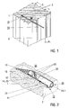
Figur 1- eine schematische Illustration der Positionierung einer erfindungsgemäßen Verankerungseinrichtung mit einer erfindungsgemäßen Sensoreinrichtung in einer Tunnelwand;
Figur 2- einen vergrößerten Ausschnitt der Verankerungs- und Sensoreinrichtungen gemäß Figur 1 in teilweiser Schnittansicht;
Figur 3- eine schematische, teilweise geschnittene Ansicht einer erfindungsgemäßen Sensoreinrichtung;
Figur 4- weitere Einzelheiten der erfindungsgemäßen Koppelung der Sensoreinrichtung mit der Verankerungseinrichtung; und
- Figuren 5 und 6
- weitere Illustrationen der Einbringung und Positionierung der erfindungsgemäßen Sensorik in einem Bohrloch.
- FIG. 1
- a schematic illustration of the positioning of an anchoring device according to the invention with a sensor device according to the invention in a tunnel wall;
- FIG. 2
- an enlarged section of the anchoring and sensor devices of Figure 1 in partial sectional view;
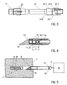
- FIG. 3
- a schematic, partially sectioned view of a sensor device according to the invention;
- FIG. 4
- further details of the coupling of the sensor device according to the invention with the anchoring device; and
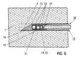
- FIGS. 5 and 6
- Further illustrations of the introduction and positioning of the sensor according to the invention in a borehole.
Figur 1 illustriert einen Ausschnitt eines Tunnels durch Felsgestein 1, in das von einer Tunnelwand 2 ausgehend Bohrlöcher 3 gebohrt sind. In einem der Bohrlöcher 3 ist ein erfindungsgemäßes seismisches Messgerät 30 (sog. seismischer Sensorstab) mit der Verankerungseinrichtung 10 (teilweise dargestellt) und der Sensoreinrichtung 20 gezeigt, deren Einzelheiten unten beschrieben sind. Die Verankerungseinrichtung 10 ist durch ein Bindemittel mit dem umgebenden Felsgestein 1 fest verbunden. Als Bindemittel wird z. B. ein Zweikomponenten-Epoxidharzkleber 4 verwendet.FIG. 1 illustrates a section of a tunnel through
Der Durchmesser a der Bohrlöcher 2 ist in Abhängigkeit vom maximalen Außendurchmesser und der Länge der Verankerungseinrichtung 10, der verwendeten Bohrtechnologie, dem Gesteinsmaterial und dessen Druckhaftigkeit gewählt. Typischerweise ist der Durchmesser a rd. 10 mm größer als der maximale Durchmesser der Verankerungseinrichtung 10, um eine gute Durchmischung des Bindemittels im Bohrloch zu gewährleisten und gleichzeitig den Bindemittelverbrauch zu begrenzen. Die Länge b der Bohrlöcher 3 ist in Abhängigkeit von der Länge der Verankerungseinrichtung 10 gewählt, die an die Zusammensetzung des Auflockerungsbereiches der Tunnelwand 2 und die bevorzugt zu messende Wellenart angepasst ist. Die Länge der Verankerungseinrichtung 10 liegt vorzugsweise im Bereich von 0.2 m bis 4 m. Der Durchmesser der Verankerungseinrichtung 10 wird in Abhängigkeit von der Größe und Anzahl der verwendeten Sensorik gewählt und liegt vorzugsweise im Bereich von 3 cm bis 4 cm.The diameter a of the
Gemäß Figur 2 umfasst die Verankerungseinrichtung 10 als rohrförmiges Mantelteil das Verankerungsrohr 11, an dessen Rohrende 15 das schiefwinkelige Spitzenelement 16 vorgesehen ist. Das Verankerungsrohr 11 und das Spitzenelement 16 sind verdrehsicher miteinander verbunden. Im Inneren des Verankerungsrohrs 11 befindet sich am Rohrende 15 die Aufnahme 12 für die Sensoreinrichtung 20. Auf der Innenwand des Verankerungsrohrs 11 ist zumindest im Bereich der Aufnahme 12 als Rohr-Gewindebereich ein gefrästes Innengewinde 14 (siehe Figur 4) zur form- und/oder kraftschlüssigen Ankoppelung der Sensoreinrichtung 10 vorgesehen.According to FIG. 2, the anchoring
Die Sensoreinrichtung 20 umfasst das Sensorteil 21 mit drei seismischen Sensoren 23 (z. B. Geofone oder Akzelerometer), die in einem Gehäuse 22 angeordnet sind. Die Gefone sind mit rechtwinkelig aufeinander stehenden Messachsen mittels Zweikomponenten-Epoxidharzkleber fest in das Gehäuse 22 eingeklebt. Auf der Außenseite des Gehäuses 22 ist ein Außengewinde 25 zur form- und/oder kraftschlüssigen Verbindung der Sensoreinrichtung 20 mit der Verankerungseinrichtung 10 vorgesehen.The
Das Sensorteil 21 ist mit dem stabförmigen Trägerteil 24 fest verbunden. Das Trägerteil 24 besteht aus glasfaserverstärktem Kunststoff. Es enthält einen zentralen Kanal 24.1, durch den Verbindungsleitungen von den Sensoren 23 an das aus der Wand 2 des Felsgesteins 1 ragenden Ende der Sensoreinrichtung 20 verlaufen.The
Figur 3 illustriert weitere Einzelheiten der erfindungsgemä-ßen Sensoreinrichtung 20 mit dem Sensorteil 21 und dem Trägerteil 24, von dem die Bereiche nahe den Enden 24.2, 24.3 gezeigt sind. Das Sensorteil 21 ist an dem ersten Ende 24.2 des Trägerteils 24 befestigt. Am entgegengesetzten, zweiten Ende 24.3 ist eine Schraubaufnahme 24.4 vorgesehen, die sich axial zum Trägerteil 24 erstreckt. In die Schraubaufnahme 24.4 ist ein Stecker 24.5 mit Epoxidharz eingeklebt. Die elektrischen Verbindungsleitungen verlaufen von den Sensoren 23 durch den Kanal 24.1 im Trägerteil 24 bis zum Stecker 24.5. Des weiteren ist an der Schraubaufnahme 24.4 eine Kontrollmarkierung 24.6 vorgesehen. Die Kontrollmarkierung 24.6 dient der Überprüfung der Orientierung der Sensoren 23, wenn die Sensoreinrichtung 20 in die Verankerungseinrichtung 10 eingeführt ist. Vorteilhafterweise wird beim Einkleben der Verankerungseinrichtung 10 die spätere Position der Sensoren festgelegt.FIG. 3 illustrates further details of the
Figur 4 illustriert die Kopplung der Sensoreinrichtung 20 mit der Verankerungseinrichtung 10 durch die Verbindung des Innengewindes 12 der Aufnahme 12 mit dem Außengewinde 25 auf dem Gehäuse 22. Die Sensoren 23 sind mit zueinander senkrechten Messachsen axial aufeinanderfolgend im Gehäuse 22 angeordnet. Die Messachse des vordersten Sensors (axialer Sensor) verläuft parallel zur Achsenrichtung des Verankerungsrohrs 11. Die Messachsen der übrigen Sensoren (radiale Sensoren) verlaufen senkrecht zur Achsenrichtung des Verankerungsrohrs 11.Figure 4 illustrates the coupling of the
Die Innen- und Außengewinde 14, 25 erstrecken sich vorzugsweise über den Bereich der radial angekoppelten Sensoren, um deren Schwingungskopplung mit der Umgebung und Signalübertragung zu verbessern. Des weiteren wird bei der Kopplung des Sensorteils 20 mit der Aufnahme 12 eine Vorspannkraft auf das axial angekoppelte Geofon erzeugt. Hierzu ist die Länge L2 des Innengewindes 14 der Verankerungseinrichtung 10 größer als die Länge L1 des Außengewindes 25 am Gehäuse 22. Beim Anliegen des Gehäuses 22 oder der Frontseite des axial angekoppelten Sensors am Rohrende 15 ist vorzugsweise rund ein Gewindegang oder 1 mm zusätzliches Gewinde am Innengewinde 25 vorhanden. Damit wird die Vorspannung des Gehäuses oder des Sensors im Gewinde und der Kraftschluss zum Verankerungsrohr erhöht.The inner and outer threads 14, 25 preferably extend over the region of the radially coupled sensors in order to improve their vibration coupling with the environment and signal transmission. Furthermore, in the coupling of the
Figur 5 illustriert, wie die Verankerungseinrichtung 10 in das Bohrloch 3 eingesetzt wird. Zunächst wird in das Bohrloch 3 ein Epoxidharzkleber 4 mit den Einzelkomponenten 4a, 4b eingeführt. In diesem Zustand sind die Einzelkomponenten 4a, 4b zur Vermeidung eines vorzeitigen Aushärtens vorzugsweise voneinander getrennt. Die Verankerungseinrichtung 10 wird mit dem geschlossenen Rohrende 15 in das Bohrloch 3 geschoben. Hierzu kann ein am entgegengesetzten, offenen Rohrende angesetztes Drehwerkzeug 30 verwendet werden, das mit einem Eingriffselement 17 am offenen Ende zusammenwirkt. Mit einem formschlüssigen Mitnehmer 31 des Drehwerkzeugs 30 wird die Verankerungseinrichtung 10 beim Vorschieben in dem Bohrloch 3 in Rotation versetzt. Bei Erreichen des Epoxidharzklebers werden die Einzelkomponenten 4a, 4b durch die Drehung des Spitzenelements 16 vermischt, so dass das Aushärten des Epoxidharzklebers beginnt.FIG. 5 illustrates how the anchoring
Die Verankerungseinrichtung 10 wird vorwärtsgeschoben oder gedreht, bis das Verankerungsrohr 11 vollständig im Bohrloch 3 angeordnet ist. Am offenen Ende des Verankerungsrohres 11 befindet sich eine Positionsmarkierung 18, mit dem die Ausrichtung der Verankerungseinrichtung 10 im Bohrloch 3 und insbesondere die Ausrichtung des Innengewindes 14 beobachtet werden kann. Alternativ kann, insbesondere bei Verwendung der Verankerungseinrichtung 10 als Wandanker das offene Ende von der Tunnelwand 2 vorstehen, um an einem Außengewinde (nicht dargestellt) eine Ankermutter anzusetzen. Wenn die Verankerungseinrichtung die gewünschte Ausrichtung im Bohrloch 3 erhalten hat, werden der Vorschub und die Drehung beendet, wobei das Bindemittel 4 aushärtet.The anchoring
Anschließend wird die Sensoreinrichtung 20 in die Verankerungseinrichtung 10 eingeschraubt, wie es in Figur 6 illustriert ist. Das Sensorteil 21 mit den Sensoren 23 wird mit dem Trägerteil 24 bis zur Aufnahme 12 vorgeschoben und durch Verschrauben der Innen- und Außengewinde 14, 25 form- und/oder kraftschlüssig mit der Verankerungseinrichtung 10 gekoppelt.Subsequently, the
Die in der vorstehenden Beschreibung, den Zeichnungen und den Ansprüchen offenbarten Merkmale der Erfindung können sowohl einzeln als auch in Kombination für die Verwirklichung der Erfindung in ihren verschiedenen Ausgestaltungen von Bedeutung sein.The features of the invention disclosed in the foregoing description, drawings and claims may be significant to the realization of the invention in its various forms both individually and in combination.
Claims (18)
Applications Claiming Priority (1)
| Application Number | Priority Date | Filing Date | Title |
|---|---|---|---|
| DE200610007474 DE102006007474B4 (en) | 2006-02-17 | 2006-02-17 | Anchoring device for a sensor device for detecting seismic signals in geological structures or structures |
Publications (2)
| Publication Number | Publication Date |
|---|---|
| EP1821119A2 true EP1821119A2 (en) | 2007-08-22 |
| EP1821119A3 EP1821119A3 (en) | 2010-06-23 |
Family
ID=38055482
Family Applications (1)
| Application Number | Title | Priority Date | Filing Date |
|---|---|---|---|
| EP07003162A Withdrawn EP1821119A3 (en) | 2006-02-17 | 2007-02-14 | Anchorage device and sensor device for a seismic measuring instrument |
Country Status (2)
| Country | Link |
|---|---|
| EP (1) | EP1821119A3 (en) |
| DE (1) | DE102006007474B4 (en) |
Families Citing this family (1)
| Publication number | Priority date | Publication date | Assignee | Title |
|---|---|---|---|---|
| CN110469354A (en) * | 2019-08-30 | 2019-11-19 | 东北大学 | A kind of anti-pulling anchor pole for country rock micro seismic monitoring |
Family Cites Families (6)
| Publication number | Priority date | Publication date | Assignee | Title |
|---|---|---|---|---|
| CH689191A5 (en) * | 1994-02-22 | 1998-11-30 | Amberg Messtechnik Ag 7320 Sar | Pickup for receiving seismic signals and using these pickup. |
| DE69517166T2 (en) * | 1994-03-30 | 2000-10-05 | Thomson Marconi Sonar Ltd | ACOUSTIC PROBE |
| DE19852455C2 (en) * | 1998-11-13 | 2003-12-24 | Geoforschungszentrum Potsdam | Anchoring device with seismic sensor |
| US6294727B1 (en) * | 1999-02-19 | 2001-09-25 | Syntron, Inc. | Takeout anchor and protective cover |
| US6307808B1 (en) * | 2000-02-01 | 2001-10-23 | Lesley J. Schmidt | Methods and apparatuses for seismic prospecting |
| DE10231780A1 (en) * | 2002-07-13 | 2004-01-29 | Ludger Boese | Seismic geophone sensor head has holder with protective casing attached to rock anchor for casing into borehole |
-
2006
- 2006-02-17 DE DE200610007474 patent/DE102006007474B4/en not_active Expired - Fee Related
-
2007
- 2007-02-14 EP EP07003162A patent/EP1821119A3/en not_active Withdrawn
Non-Patent Citations (1)
| Title |
|---|
| GUSTAV ADLHOCH: "Interview - KEM vor ort", 22 March 2005 (2005-03-22), XP055247841, Retrieved from the Internet <URL:https://kem.industrie.de/allgemein/interview-kem-vor-ort-10/> [retrieved on 20160205] * |
Also Published As
| Publication number | Publication date |
|---|---|
| EP1821119A3 (en) | 2010-06-23 |
| DE102006007474B4 (en) | 2008-07-31 |
| DE102006007474A1 (en) | 2007-08-30 |
Similar Documents
| Publication | Publication Date | Title |
|---|---|---|
| DE3400182C2 (en) | ||
| EP2257690B1 (en) | Corrosion-protected self-drilling anchor and anchor subunit and method for the production thereof | |
| DE2707238B2 (en) | Corrosion-protected tension member for a prestressable anchor in solid rock | |
| EP3507509B1 (en) | Distance sensor on anchor tip | |
| EP1888878B1 (en) | Method and device for drilling, particularly percussion drilling or rotary percussion drilling a hole in soil or rock material | |
| DE102014104552A1 (en) | Drilling head and device for making a hole in the ground | |
| EP1381756B2 (en) | Method and device for drilling a hole and for securing an anchorage in a bore hole | |
| DE10336043A1 (en) | Xings | |
| EP1001134A1 (en) | Anchoring device with a seismic sensor | |
| DE4204533C2 (en) | Injection drill anchor | |
| DE102006007474B4 (en) | Anchoring device for a sensor device for detecting seismic signals in geological structures or structures | |
| WO2013053352A1 (en) | Fixing arrangement comprising bifunctional screw | |
| DE102005015494B4 (en) | bayonet coupling | |
| DE2611677B2 (en) | Device for introducing pipes | |
| AT413231B (en) | METHOD AND DEVICE FOR DRILLING HOLES IN SOIL OR ROCK MATERIAL | |
| DE4032682C2 (en) | Mountain anchors | |
| AT394449B (en) | Device for determining tensile and/or compressive stresses, and method for putting said device in place | |
| EP2146050A2 (en) | Setting method of a self-drilling chemically anchored attachment element | |
| AT525566B1 (en) | SENSOR-BASED HOLLOW ROD SYSTEM | |
| DE10231779B3 (en) | Device for positioning a measuring head provided with at least one seismic sensor | |
| AT505335B1 (en) | DEVICE FOR MANUFACTURING A DRILL BIT IN ROCK MATERIAL | |
| DE19842173A1 (en) | Screw with self-ridging screw connection, for use as coupling device between machine casing and accelerometer; has nonpositively acting surface area to form primary connection and only has positively acting surface with secondary action | |
| DE2624393C3 (en) | Methods and devices for the oriented removal of drill cores | |
| DE102007000360A1 (en) | Chemically anchorable fastener | |
| DE3025422C2 (en) | Device for fastening a rotary element in the deepest part of a borehole |
Legal Events
| Date | Code | Title | Description |
|---|---|---|---|
| PUAI | Public reference made under article 153(3) epc to a published international application that has entered the european phase |
Free format text: ORIGINAL CODE: 0009012 |
|
| AK | Designated contracting states |
Kind code of ref document: A2 Designated state(s): AT BE BG CH CY CZ DE DK EE ES FI FR GB GR HU IE IS IT LI LT LU LV MC NL PL PT RO SE SI SK TR |
|
| AX | Request for extension of the european patent |
Extension state: AL BA HR MK YU |
|
| RAP1 | Party data changed (applicant data changed or rights of an application transferred) |
Owner name: HELMHOLTZ-ZENTRUM POTSDAM DEUTSCHES GEOFORSCHUNGSZ |
|
| PUAL | Search report despatched |
Free format text: ORIGINAL CODE: 0009013 |
|
| AK | Designated contracting states |
Kind code of ref document: A3 Designated state(s): AT BE BG CH CY CZ DE DK EE ES FI FR GB GR HU IE IS IT LI LT LU LV MC NL PL PT RO SE SI SK TR |
|
| AX | Request for extension of the european patent |
Extension state: AL BA HR MK RS |
|
| 17P | Request for examination filed |
Effective date: 20101210 |
|
| AKX | Designation fees paid |
Designated state(s): AT CH FR IT LI |
|
| REG | Reference to a national code |
Ref country code: DE Ref legal event code: R108 Effective date: 20110201 Ref country code: DE Ref legal event code: 8566 |
|
| 17Q | First examination report despatched |
Effective date: 20160210 |
|
| GRAP | Despatch of communication of intention to grant a patent |
Free format text: ORIGINAL CODE: EPIDOSNIGR1 |
|
| STAA | Information on the status of an ep patent application or granted ep patent |
Free format text: STATUS: GRANT OF PATENT IS INTENDED |
|
| INTG | Intention to grant announced |
Effective date: 20180323 |
|
| STAA | Information on the status of an ep patent application or granted ep patent |
Free format text: STATUS: THE APPLICATION IS DEEMED TO BE WITHDRAWN |
|
| 18D | Application deemed to be withdrawn |
Effective date: 20180803 |