BACKGROUND OF THE INVENTION
Field of the Invention
-
The present invention relates to an anamorphic
converter used with image-taking devices such as film
cameras, television cameras, video cameras, or the like, for
taking pictures with an aspect ratio which differs from that
of the imaging device.
Description of the Related Art
-
Various techniques for recording and playback of
images with conversion of aspect ratio have been
conventionally proposed. Particularly, in the field of
cinematography, a technique is widely used with a
Cinemascope format (aspect ratio 2.35:1) picture
recording/playback system wherein the picture is optically
horizontally compressed using an anamorphic lens so as to be
taken on film, and also shown at the time of playback by
optically horizontally expanding the image on film using an
anamorphic lens.
-
Known anamorphic converters include front
converters which are attached to the object side of an
image-formation optical system, such as disclosed in
Japanese Patent Laid-Open No. 2-13916 and Japanese Patent
Laid-Open No. 6-82691, for example. These converters are
simple and do not exhibit vignetting because they ensure a
suitable effective diameter regardless of the conversion
ratio. Also, with regard to such front converters, Japanese
Patent Laid-Open No. 3-25407 and Japanese Patent Laid-Open
No. 5-188271, for example, propose techniques for correcting
astigmatism due to focus.
-
Also, with regard to a rear converter to be
attached to the image side of an image-formation optical
system, the arrangement described in Japanese Patent
Publication 3,021,985 (corresponding U.S. Patent No.
5,307,084) with reduced change in astigmatism due to focus
is known. Further, there is known a converter, such as
described in U.S. Patent No. 5,668,666, having a built-in
converter and capable of being detachably inserted to the
image side of the focusing group of the image-formation
optical system. This built-in converter also is capable of
reducing change in astigmatism.
-
Now, in recent years, video technology has seen a
trend toward higher definition, to where digital cinema
systems wherein cinematography carried out using HDTV
systems are becoming commonplace. While imaging devices
having an aspect ratio of 16:9 (1.78:1) are common with
digital cinema systems, there is demand for an anamorphic
converter for improving image quality by effectively
utilizing pixels on the imaging device side in order to
shoot pictures in the 2.35:1 aspect ratio Cinemascope format.
Prerequisites for a cinematography anamorphic converter are
that suitable aspect ratio conversion is performed, that
there is no vignetting, that the effective image field of
the image-formation optical system can be fully utilized,
that there is little drop in light quantity at the periphery,
and that high optical capabilities can be had over the
entire zooming/focusing range of the image-formation optical
system.
-
Now, although the front converter disclosed in
Japanese Patent Laid-Open No. 2-13916 and Japanese Patent
Laid-Open No. 6-82691 are advantageous in being simple, and
not exhibiting vignetting due to ensuring a suitable
effective diameter regardless of the conversion ratio,
however, further improvements are desired with regard to
larger size and change in astigmatism due to focusing. Also,
the arrangements disclosed in Japanese Patent Laid-Open No.
3-25407 and Japanese Patent Laid-Open No. 5-188271 enable
correcting of astigmatism due to focus. However, correcting
means within the converter must be driven synchronously with
the focusing of the image-formation optical system, thereby
necessitating a complicated mechanism.
-
Also, the rear converter disclosed in Japanese
Patent Publication 3,021,985 is advantageous in that there
is no change in astigmatism due to focusing, but there is
the need to suitably set the horizontal and vertical
conversion scaling to suppress vignetting, and improvement
is desired regarding change in field angle of the image-formation
optical system. Further, the built-in converter
disclosed in USP 5,668,666 also is advantageous in that
there is little change in astigmatism due to focusing, but
has a problem in that angular magnification is smaller than
1, and vignetting occurs.
SUMMARY OF THE INVENTION
-
The present invention is directed to an anamorphic
converter suitable for digital cinematography, small in size
and having excellent optical performance.
-
According to a first aspect of the present
invention, an anamorphic converter, which can be inserted
into and removed from a lens group of an image-formation
optical system, includes an anamorphic lens that satisfies
the following conditions:
0.9 < (AR1 · βx) / (AR2 · βy) < 1.1
(AR22 + 1) · βy2 / (AR12 + 1) > 1
βx represents a first focal distance magnification scale at
a first cross-section containing an optical axis of the
anamorphic lens. βy represents a second focal distance
magnification scale at a second cross-section which is
perpendicular to the first cross-section and contains the
optical axis. AR1 represents an aspect ratio of an image-taking
range in a field of the image-formation optical
system, and AR2 represents an aspect ratio at an effective
range of an image-taking unit disposed at an object image
side of the lens group.
-
According to a second aspect of the present
invention, an anamorphic converter disposed at an object
side of an image-formation optical system includes at least
two anamorphic lenses a1 and a2 positioned in order from the
object side. The anamorphic lenses satisfying the following
conditions:
ϕa1 > 0
ϕa2 < 0
ϕa1 and ϕa2 represent refractive powers of the anamorphic
lens a1 and the anamorphic lens a2, at a first cross-section
containing an optical axis of the anamorphic lenses and
perpendicular to a second cross-section containing the
optical axis.
-
According to the present invention, an anamorphic
converter can be realized which is suitable for digital
cinematography, and small in size and having excellent
optical performance.
-
Further features and advantages of the present
invention will become apparent from the following
description of exemplary embodiments with reference to the
attached drawings.
BRIEF DESCRIPTION OF THE DRAWINGS
-
Figs. 1A and 1B are diagrams illustrating a
configuration of a first embodiment of the present invention.
Fig. 1A is a cross-sectional diagram illustrating a lens
configuration in the Y direction with an anamorphic
converter inserted, and Fig. 1B is a cross-sectional diagram
illustrating the lens configuration in the X direction with
the anamorphic converter inserted.
-
Fig. 2 is a conceptual diagram of aspect ratio, for
describing the first embodiment of the present invention.
-
Fig. 3 is a conceptual diagram of an image circle
and image-taking range in the field of an image-formation
optical system according to the first embodiment of the
present invention.
-
Fig. 4 is a conceptual diagram of an image circle
and image-taking range following conversion by a converter,
according to the first embodiment of the present invention.
-
Fig. 5 is a conceptual diagram of the effective
range of image-taking unit, according to the first
embodiment of the present invention.
-
Fig. 6 is a conceptual diagram of the display
region of the output image at the time of showing, according
to the first embodiment of the present invention.
-
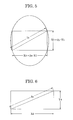
Fig. 7 is a conceptual diagram of aspect ratio, for
describing a second embodiment of the present invention.
-
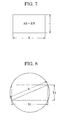
Fig. 8 is a conceptual diagram of an image circle
and image-taking range in the field of an image-formation
optical system according to the second embodiment of the
present invention.
-
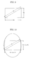
Fig. 9 is a conceptual diagram of an image circle
and image-taking range following conversion by a converter,
according to the second embodiment of the present invention.
-
Fig. 10 is a conceptual diagram of the effective
range of image-taking unit, according to the second
embodiment of the present invention.
-
Fig. 11 is a conceptual diagram of the display
region of the output image at the time of showing, according
to the second embodiment of the present invention.
-
Figs. 12A and 12B are conceptual diagrams for
describing aspect ratio conversion methods according to the
second embodiment of the present invention.
-
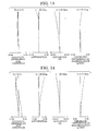
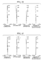
Fig. 13 is a diagram of longitudinal aberration in
the X direction, in a numerical example according to the
first embodiment wherein fx = 10.3 mm, fy = 13.6 mm, and
object distance is 2.5 m.
-
Fig. 14 is a diagram of longitudinal aberration in
the Y direction, in a numerical example according to the
first embodiment wherein fx = 10.3 mm, fy = 13.6 mm, and
object distance is 2.5 m.
-
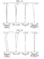
Fig. 15 is a diagram of longitudinal aberration in
the X direction, in a numerical example according to the
first embodiment wherein fx = 39.5 mm, fy = 52.1 mm, and
object distance is 2.5 m.
-
Fig. 16 is a diagram of longitudinal aberration in
the Y direction, in a numerical example according to the
first embodiment wherein fx = 39.5 mm, fy = 52.1 mm, and
object distance is 2.5 m.
-
Fig. 17 is a diagram of longitudinal aberration in
the X direction, in a numerical example according to the
first embodiment wherein fx = 151.1 mm, fy = 199.7 mm, and
object distance is 2.5 m.
-
Fig. 18 is a diagram of longitudinal aberration in
the Y direction, in a numerical example according to the
first embodiment wherein fx = 151.1 mm, fy = 199.7 mm, and
object distance is 2.5 m.
-
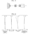
Fig. 19 is a cross-sectional diagram illustrating
the lens configuration at the wide-angle end before
inserting the anamorphic converter, according to the first
embodiment.
-
Fig. 20 is a diagram of longitudinal aberration in
a numerical example according to the first embodiment before
inserting the anamorphic converter, wherein f = 10.3 mm, and
object distance is 2.5 m.
-
Fig. 21 is a diagram of longitudinal aberration in
a numerical example according to the first embodiment before
inserting the anamorphic converter, wherein f = 39.5 mm, and
object distance is 2.5 m.
-
Fig. 22 is a diagram of longitudinal aberration in
a numerical example according to the first embodiment before
inserting the anamorphic converter, wherein f = 151.1 mm,
and object distance is 2.5 m.
-
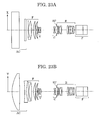
Figs. 23A and 23B are diagrams illustrating the
configuration of the second embodiment of the present
invention. Fig. 23A is a cross-sectional diagram
illustrating the lens configuration in the X direction with
an anamorphic converter inserted, and Fig. 23B being a
cross-sectional diagram illustrating the lens configuration
in the Y direction with the anamorphic converter inserted.
-
Fig. 24 is a diagram of longitudinal aberration in
the X direction at the wide angle end in a numerical example
according to the second embodiment, wherein object distance
is at infinity.
-
Fig. 25 is a diagram of longitudinal aberration in
the Y direction at the wide angle end in a numerical example
according to the second embodiment, wherein object distance
is at infinity.
-
Fig. 26 is a diagram of longitudinal aberration in
the X direction in a numerical example according to the
second embodiment, wherein fx = 38.85 mm, fy = 51.36 mm, and
object distance is at infinity.
-
Fig. 27 is a diagram of longitudinal aberration in
the Y direction in a numerical example according to the
second embodiment, wherein fx = 38.85 mm, fy = 51.36 mm, and
object distance is at infinity.
-
Fig. 28 is a diagram of longitudinal aberration in
the X direction at the telephoto angle end in a numerical
example according to the second embodiment, wherein object
distance is at infinity.
-
Fig. 29 is a diagram of longitudinal aberration in
the Y direction at the telephoto end in a numerical example
according to the second embodiment, wherein object distance
is at infinity.
-
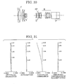
Fig. 30 is a cross-sectional diagram illustrating
the lens configuration at the wide-angle end before
inserting the anamorphic converter, according to the second
embodiment.
-
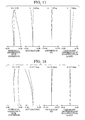
Fig. 31 is a diagram of longitudinal aberration at
the wide angle end in a numerical example according to the
second embodiment, wherein object distance of the image-formation
optical system is at infinity.
-
Fig. 32 is a diagram of longitudinal aberration in
a numerical example according to the second embodiment,
wherein f = 38.85 mm, wherein object distance of the image-formation
optical system is at infinity.
-
Fig. 33 is a diagram of longitudinal aberration at
the telephoto end in a numerical example according to the
second embodiment, wherein object distance of the image-formation
optical system is at infinity.
DESCRIPTION OF THE EMBODIMENTS
First Embodiment
-
Next, description will be made regarding a first
embodiment of an anamorphic converter which can be inserted
into and detached from a lens group at the image side of an
image-formation optical system (focusing lens group) F. Fig.
2 is a conceptual diagram of aspect ratio, for describing
the present embodiment, Fig. 3 is a conceptual diagram of an
image circle and image-taking range in the field of an
image-formation optical system according to the present
embodiment, Fig. 4 is a conceptual diagram of an image
circle and image-taking range following conversion by a
converter, according to the present embodiment, Fig. 5 is a
conceptual diagram of the effective range of image-taking
unit, according to the first embodiment of the present
invention, and Fig. 6 is a conceptual diagram of the display
region of the output image at the time of showing, according
to the first embodiment of the present invention.
-
With the anamorphic converter according to the
present embodiment, suitable aspect ratio conversion can be
performed without vignetting, by means of appropriately
stipulating conversion magnification with the following
settings of conditions:
0.9 < (AR1 · βx) / (AR2 · βy) < 1.1
(AR22 + 1) · βy2 / (AR12 + 1) > 1
wherein βx represents the focal distance magnification scale
at an arbitrary cross-section X containing the optical axis
of the anamorphic converter, βy represents the focal
distance magnification scale at a cross-section Y which is
perpendicular to the cross-section X and contains the
optical axis, AR1 represents the aspect ratio of the image-taking
range in the field of the image-formation optical
system, and AR2 represents the aspect ratio at the effective
range of the image-taking unit. Expression (1) is the
condition for executing suitable aspect ratio conversion.
-
With reference to Fig. 2, the aspect ratio AR is
expressed as:
AR = X / Y
in which the horizontal length of the field is X and the
vertical length of the field is Y.
-
Fig. 3 is a model diagram of the imaging range of
the image-formation optical system, and Fig. 4 is a model
diagram of the imaging range of the imaging unit. In Fig. 3,
X1 is the horizontal length of effective screen dimensions
of the imaging range for the field of the image-formation
optical system, Y1 is the vertical length thereof, and AR1
is the aspect ratio thereof. X2 is the horizontal length
for the imaging range of the imaging unit, Y2 is the
vertical length thereof, and AR2 is the aspect ratio thereof.
As such, the relation thereof is expressed as follows:
AR1 / AR2 = (X1 · Y2) / (X2 · Y1)
-
Also, Fig. 5 is a conceptual diagram of the imaging
range following aspect ratio conversion with the anamorphic
converter. In order for suitable aspect ratio conversion to
be performed, the conversion magnification βx in the
horizontal direction of the anamorphic converter and the
conversion magnification βy in the vertical direction can be
expressed as follows:
βx = X2 / X1
βy = Y2 / Y1
According to Expressions (6) through (8), the condition for
ideal aspect ratio conversion is as follows:
(AR1 · βx) / (AR2 · βy) = 1
-
In practice, a margin of error of about 10% is
almost indiscernible visually, so that suitable aspect ratio
conversion can be realized by satisfying Expression (1).
-
Expression (2) shows the conditions for preventing
vignetting accompanying aspect ratio conversion. In a case
of disposing the converter at the image side of the image-formation
optical system, the image circle is restricted by
the effective diameter of the image-formation optical system
side, and accordingly a conversion magnification smaller
than 1 does not yield a wide angle. Rather, vignetting
occurs at the periphery of the image. The image circle I1
of the image-formation optical system shown in Fig. 3 is
represented by the following:
I1 = (X12 + Y12) 1/2 = Y1 · (AR12 + 1) 1/2
-
Also, the diagonal length I2 of the imaging unit
shown in Fig. 4 is represented by the following:
I2 = (X22 + Y22) 1/2 = βy · Y1 · (AR22 + 1) 1/2
-
Further, the diagonal length I3 of the subjected to
aspect ratio conversion with the anamorphic converter as
shown in Fig. 5 is represented by the following:
I3 = {(βx · X1)2 + (βy · Y1)2}1/2 = βy · Y1 · (AR22 + 1)1/2
-
Accordingly, I3 > I2 must hold in order for the
image following aspect ratio conversion to encompass the
diagonal length of the imaging unit and to prevent
vignetting. Hence, from Expressions (11) and (12),
I32 / I22 > 1
-
Normally, the image circle I1 of the image formation
optical system can be considered to be approximately equal
to the diagonal length I2 of the imaging unit, and
accordingly,
I32 / I12 > 1
and
{βy2 · (AR22 + 1)} / (AR12 + 1) > 1
-
Fig. 6 is a conceptual diagram of an output image
at the time of showing. For projection, aspect ratio
conversion opposite to that at the time of shooting must be
performed, so as to return the aspect ratio to the original
aspect ratio. Accordingly, the horizontal length X4 and
vertical length Y4 in Fig. 6 can be respectively expressed
by:
X4 = βx' · X2
Y4 =βy' · Y2
The conversion magnifications βx' and βy' can be
respectively expressed by:
βx' = m/βx
βy' = m/βy
wherein m is an arbitrary constant.
-
Note that generally, the image circle of an image
formation optical system changes depending on zooming,
focusing, and aperture. The conditions given in Expression
(2) are calculated based on conditions wherein the image
circle is the smallest, enabling an arrangement wherein
there is no vignetting even in the event that the left side
of Expression (2) is smaller than 1 in the event that the
image circle I1 can be ensured to be larger than the
diagonal length I2 of the imaging unit by restricting the
range of use of zooming, focusing, and aperture with the
image-formation optical system.
-
Also, with the present configuration example, the
configuration of the anamorphic converter for being
removably inserted into the image-formation optical system
for aspect ratio conversion can be suitably stipulated by
setting conditions as:
ϕa1 > 0
ϕa2 < 0
wherein the anamorphic converter has at least two anamorphic
lenses a1 and a2 in that order from the object side, and
wherein ϕa1 and ϕa2 represent the refractive power at an
arbitrary cross-section X containing the optical axis or
cross-section Y perpendicular to the cross-section X and
containing the optical axis, for the anamorphic lenses a1
and a2, respectively.
-
In order to have different conversion
magnifications for the cross-section X and cross-section Y,
there is the need to use what is known as a toric lens
having different curvatures for the X cross-section and the
Y cross-section, or use at least two cylindrical lenses
having curvature for only one cross-section, thereby forming
an afocal converter (anamorphic converter) with different
angular magnifications for the X cross-section and the Y
cross-section. Particularly, in order to satisfy the
conditions of Expression (2) and prevent vignetting, βx > 1
and βy > 1 must hold. Accordingly, the anamorphic converter
at the X cross-section or Y cross-section must be a tele-converter
type with a positive-negative configuration from
the object side.
-
As described above, with an arrangement wherein an
anamorphic converter is disposed on the image side of the
image-formation optical system as with the present
embodiment, stipulating conditions for conversion
magnification for the X and Y cross-sections containing the
optical axis, and appropriately setting the lens
configuration, enables realization of a built-in type
anamorphic converter with excellent optical capabilities and
no vignetting, optimal for digital cinematography in
particular.
Second Embodiment
-
Next, as a second embodiment of the present
invention, an anamorphic converter disposed on the object
side of the image-formation optical system will be described.
Fig. 7 is a conceptual diagram of aspect ratio, for
describing the present embodiment, Fig. 8 is a conceptual
diagram of an image circle and image-taking range in the
field of an image-formation optical system according to the
present embodiment, Fig. 9 is a conceptual diagram of an
image circle and image-taking range following conversion by
a converter, according to the present embodiment, Fig. 10 is
a conceptual diagram of the effective range of image-taking
unit, according to the present embodiment, Fig. 11 is a
conceptual diagram of the display region of the output image
at the time of showing, according to the present embodiment,
and Figs. 12A and 12B are conceptual diagrams for describing
aspect ratio conversion methods according to the present
embodiment.
-
With the anamorphic converter according to the
present invention, the vertical direction can be enlarged to
obtain the intended aspect ratio by setting the following
conditions:
ϕa1 > 0
ϕa2 < 0
wherein the anamorphic converter has at least two anamorphic
lenses a1 and a2 in that order from the object side, and
wherein ϕa1 and ϕa2 represent the refractive power at an
arbitrary cross-section X containing the optical axis or
cross-section Y perpendicular to the cross-section X and
containing the optical axis, for the anamorphic lenses a1
and a2, respectively.
-
Now, with the horizontal direction including the
optical axis as cross-section X with reference to the image-taking
screen as a reference, and a cross-section
perpendicular to the cross-section X as a cross-section Y,
in order to have different conversion magnifications for the
cross-section X (horizontal direction) and cross-section Y
(vertical direction), there is the need to use at least two
cylindrical lenses or toric lenses, forming an afocal
converter (anamorphic converter) with different angular
magnifications for the X cross-section and the Y cross-section.
Further, in order to realize an enlarging system
for the cross-section Y direction alone, the anamorphic
converter must be a tele-converter type with a positive-negative
configuration from the object side of an anamorphic
lens having positive power ϕa1 for the cross-section Y
direction and an anamorphic lens having negative power ϕa2
for the cross-section Y direction.
-
Also, with the anamorphic converter disposed on the
object side of the image-formation optical system according
to the present embodiment, in the event of converting a
picture with an aspect ratio of 2.35:1 into a picture with
an aspect ratio of 16:9, there are two conceivable ways, one
being the method for enlarging in the vertical direction as
shown in Fig. 12A, and the other being the method for
compressing in the horizontal direction as shown in Fig. 12B.
Unlike the case wherein the anamorphic converter is disposed
at the image side of the image-formation optical system,
there is no vignetting with either method, but with the
conventional techniques, a reduction system for compressing
in the horizontal direction as shown in Fig. 12B requires
that the field angle in the horizontal direction be ensured,
resulting in the size of the anamorphic converter increasing.
Also, the anamorphic converter has refractive power in the
horizontal direction which is the longer dimensions of the
effective screen, leading to deterioration of optical
performance, such as deterioration in image-formation
performance at the screen periphery, and distortion
occurring. With the present invention, the vertical
direction is enlarged as shown in Fig. 12A, so the
anamorphic converter has refractive power in the vertical
direction which is the shorter dimensions of the effective
screen, thereby realizing a small and lightweight anamorphic
converter wherein there is little deterioration of optical
performance such as deterioration in image-formation
performance at the screen periphery and distortion.
-
Also, with the anamorphic converter according to
the present embodiment, suitable aspect ratio conversion can
be performed by means of appropriately settings conditions
as follows:
0.9 < (AR1 · βx) / (AR2 · βy) < 1.1
wherein βx represents the focal distance magnification scale
at an arbitrary cross-section X containing the optical axis
of the anamorphic converter, βy represents the focal
distance magnification scale at a cross-section Y which is
perpendicular to the cross-section X and contains the
optical axis, AR1 represents the aspect ratio of the image-taking
range in the field of the image-formation optical
system, and AR2 represents the aspect ratio at the effective
range of the image-taking unit disposed at the image side of
the image-formation optical system. Expression (2-1) is the
condition for executing suitable aspect ratio conversion.
-
With reference to Fig. 7, the aspect ratio AR is
expressed as
AR = X / Y
wherein X is the horizontal length of the field and Y is the
vertical length of the field.
-
Fig. 8 is a model diagram of the imaging range of
the image-formation optical system, and Fig. 9 is a model
diagram of the imaging range of the imaging unit. With the
horizontal length of effective screen dimensions of the
imaging range in Fig. 8 for the field of the image-formation
optical system as X1, the vertical length thereof as Y1, and
the aspect ratio thereof as AR1, and further, with the
horizontal length for the field of the imaging unit in Fig.
9 as X2, the vertical length thereof as Y2, and the aspect
ratio thereof as AR2, the relation thereof is expressed as
follows:
AR1 / AR2 = (X1 · Y2) / (X2 · Y1)
-
Also, Fig. 10 is a conceptual diagram of the
imaging range following aspect ratio conversion with the
anamorphic converter. In order for suitable aspect ratio
conversion to be performed, the conversion magnification βx
in the horizontal direction of the anamorphic converter and
the conversion magnification βy in the vertical direction
can be expressed as follows,
βx = X2 / X1
βy = Y2 / Y1
According to Expressions (4-1) through (6-1), the condition
for ideal aspect ratio conversion is as follows:
(AR1 · βx) / (AR2 · βy) = 1
-
In practice, a margin of error of about 10% is
almost visually indiscernible, so suitable aspect ratio
conversion can be realized by satisfying Expression (2-1).
-
Fig. 11 is a conceptual diagram of an output image
at the time of showing. For projection, aspect ratio
conversion opposite to that at the time of shooting must be
performed, so as to return the aspect ratio to the original
aspect ratio. Accordingly, the horizontal length X4 and
vertical length Y4 in Fig. 11 can be respectively expressed
by
X4 = βx' · X2
Y4 = βy' · Y2
The conversion magnifications βx' and βy' can be
respectively expressed by
βx' = m/βx
βy' = m/βy
wherein m is an arbitrary constant.
-
As described above, with an arrangement wherein an
anamorphic converter is disposed on the object side of the
image-formation optical system as with the present
embodiment, a front converter type anamorphic converter
which is small and has high optical performance, optimal for
digital cinematography in particular, can be realized by
stipulating conditions for conversion magnification of
cross-sections X and Y containing the optical axis, and
setting the lens configuration appropriately.
First Embodiment
-
Now, embodiments of the present invention will be
described. The configuration of a first embodiment of the
present invention wherein an arrangement including an
anamorphic converter disposed at the image side of the
image-formation optical system is applied, will be described
now.
-
Figs. 1A and 1B are diagrams illustrating the
configuration of the first embodiment of the present
invention. Fig. 1A is a cross-sectional diagram
illustrating the lens configuration in the Y direction with
an anamorphic converter inserted, and Fig. 1B is a cross-sectional
diagram illustrating the lens configuration in the
X direction with the anamorphic converter inserted. Fig. 13
is a diagram of longitudinal aberration in the X direction,
in a numerical example according to the first embodiment
wherein fx = 10.3 mm, fy = 13.6 mm, and object distance is
2.5 m. Fig. 14 is a diagram of longitudinal aberration in
the Y direction, in a numerical example according to the
first embodiment wherein fx = 10.3 mm, fy = 13.6 mm, and
object distance is 2.5 m. Fig. 15 is a diagram of
longitudinal aberration in the X direction, in a numerical
example according to the first embodiment wherein fx = 39.5
mm, fy = 52.1 mm, and object distance is 2.5 m. Fig. 16 is
a diagram of longitudinal aberration in the Y direction, in
a numerical example according to the first embodiment
wherein fx = 39.5 mm, fy = 52.1 mm, and object distance is
2.5 m. Fig. 17 is a diagram of longitudinal aberration in
the X direction, in a numerical example according to the
first embodiment wherein fx = 151.1 mm, fy = 199.7 mm, and
object distance is 2.5 m. Fig. 18 is a diagram of
longitudinal aberration in the Y direction, in a numerical
example according to the first embodiment wherein fx = 151.1
mm, fy = 199.7 mm, and object distance is 2.5 m.
-
Further, Fig. 19 is a cross-sectional diagram
illustrating the lens configuration at the wide-angle end
before inserting the anamorphic converter, according to the
first embodiment. Fig. 20 is a diagram of longitudinal
aberration in a numerical example according to the first
embodiment before inserting the anamorphic converter,
wherein f = 10.3 mm, and object distance is 2.5 m. Fig. 21
is a diagram of longitudinal aberration in a numerical
example according to the first embodiment before inserting
the anamorphic converter, wherein f = 39.5 mm, and object
distance is 2.5 m. Fig. 22 is a diagram of longitudinal
aberration in a numerical example according to the first
embodiment before inserting the anamorphic converter,
wherein f = 151.1 mm, and object distance is 2.5 m. Figs.
23A and 23B are diagrams illustrating the configuration of a
second embodiment of the present invention. Fig. 23A is a
cross-sectional diagram illustrating the lens configuration
in the X direction with an anamorphic converter inserted,
and Fig. 23B being a cross-sectional diagram illustrating
the lens configuration in the Y direction with the
anamorphic converter inserted.
-
In Figs. 1A and 1B, reference character F denotes a
front lens group for positive refractive power serving as a
first group. Reference character V denotes a variator for
negative refractive power for variable magnification,
serving as a second group, which changes magnification from
wide-angle to telephoto by simply moving along the optical
axis to the field side. Reference character C is a
compensator for negative refractive power, serving as a
third group, and non-linearly moves on the optical axis to
the object side following a convex track, in order to
correct image shifting accompanying variation of
magnification. The variator V and compensator C make up the
magnification variation system. Further, reference
character SP denotes the aperture (stop) and R denotes a
relay group serving as a fourth group for fixed positive
refractive power in variable magnification. Preference
character P denotes a color separation prism or optical
filter or the like, illustrated as a glass block in Fig. 1.
-
With the present embodiment, a device including the
first through fourth groups is defined as a lens device, a
device having a color separation prism or optical filter and
imaging device disposed closer to the object side from the
fourth group is defined as a camera device, and a device
having the lens device and camera device such that the lens
device and camera device are capable of being detachably
mounted is defined as an image-taking device.
-
Next, the features of the fourth group according to
the present embodiment will be described. The fourth group
has a generally afocal space A, with the anamorphic
converter AN removably inserted in the space A. The
anamorphic converter AN is configured of two cylindrical
lenses a1 and a2, with each cylindrical lens having zero
curvature in the X direction, only curvature in the Y
direction. The Y-directional refractive power ϕa1 and ϕa2
of the cylindrical lenses a1 and a2 is
ϕa1 = +0.0162
and
ϕa2 = -0.0214
respectively, satisfying the conditions of Expressions (3)
and (4).
-
The aspect ratio AR1 of the imaging range of the
field of the image-formation optical system and the aspect
ratio AR2 of the effecting range of the imaging unit are
AR1 = 2.35
AR2 = 1.78
The conversion magnification βx in the X direction and the
conversion magnification βy in the Y direction are
βx = 1.0
βy = 1.32
Accordingly, the values of the conditional expressions are
(AR1 · βx) / (AR2 · βy) = 1.00
(AR22 + 1) · βy2 / (AR12 + 1) = 1.11
thereby satisfying the conditions of Expressions (1) and (2),
thus realizing a built-in converter type anamorphic
converter with excellent optical properties and no
vignetting.
-
The following shows numerical examples according to
the present embodiment.
| Numerical Examples according to the First Embodiment |
| fx= 10.3~151.1 |
| fy= 13.6~199.7 fn0=1:2.05~2.32 2* = 56.2deg.~4.2deg. |
| r 1= | 1169.481 | d 1= | 2.40 | n 1= | 1.81265 | v 1= | 25.4 |
| r 2= | 98.429 | d 2= | 10.83 | n 2 | 1.51825 | v 2 | 64.2 |
| r 3= | 265.170 | d 3 | 0.20 |
| r 4= | 124.037 | d 4= | 8.29 | n 3 | 1.60548 | v 3= | 60.7 |
| r 5= | -281.395 | d 5= | 0.20 |
| r 6= | 51.797 | d 6= | 6.46 | n 4= | 1.64254 | v 4= | 60.1 |
| r 7= | 97.915 | d 7= | variable |
| r 8= | 71.045 | d 8= | 0.90 | n 5= | 1.82017 | v 5= | 46.6 |
| r 9= | 17.601 | d 9= | 6.01 |
| r10= | -21.542 | d10= | 0.90 | n 6 | 1.77621 | v 6= | 49.6 |
| r11= | 18.397 | d11= | 4.63 | n 7= | 1.85501 | v 7= | 23.9 |
| r12= | -4295.134 | d12= | variable |
| r13= | 27.245 | d13 | 0.90 | n 8= | 1.79013 | v 8= | 44.2 |
| r14= | 31.613 | d14= | 3.84 | n 9 | 1.85501 | v 9= | 23.9 |
| r15= | 1125.345 | d15= | variable |
| r16= | 0.000 (aperture) | d16= | 1.60 |
| r17= | 10000.000 | d17= | 4.02 | n10 | 1.73234 | v10= | 54.7 |
| r18= | -32.342 | d18= | 0.20 |
| r19= | 107.938 | d19 | 3.60 | n11= | 1.48915 | v11= | 70.2 |
| r20= | 121.402 | d20 | 0.20 |
| r21= | 37.891 | d21= | 7.17 | n12= | 1.48915 | v12 | 70.2 |
| r22= | 36.452 | d22 | 1.20 | n13= | 1.83932 | v13= | 37.2 |
| r23= | 177.431 | d23= | 7.00 |
| r24= | 44.041 | d24= | 4.62 | n14= | 1.60548 | v14= | 60.6 |
| r25= | -238.800 | d25= | 11.67 |
| r26= | -868.640 | d26= | 1.50 | n15= | 1.60718 | v15= | 38.0 |
| r27= | 29.333 | d27= | 10.21 |
| r28= | 48.564 | d28= | 4.26 | n16= | 1.48915 | v16= | 70.2 |
| r29= | 193.706 | d29 | 0.20 |
| r30= | -210.911 | d30 | 1.20 | n17= | 1.83932 | v17= | 37.2 |
| r31= | 39.960 | d31= | 6.49 | n18= | 1.48915 | v18 | 70.2 |
| r32= | 33.683 | d32 | 0.20 |
| r33= | 43.464 | d33= | 6.21 | n19= | 1.53430 | v19 = | 48.8 |
| r34= | -30.063 | d34= | 1.20 | n20= | 1.80811 | v20= | 46.6 |
| r35 | 113.246 | d35= | 0.20 |
| r36= | 56.783 | d36= | 2.98 | n21 | 1.55098 | v21= | 45.8 |
| r37= | -10000.000 | d37= | 3.80 |
| r38= | 0.000 | d38= | 30.00 | n22= | 1.60718 | v22 | 38.0 |
| r39= | 0.000 | d39= | 16.20 | n23= | 1.51825 | v23= | 64.2 |
| r40= | 0.000 |
| Note: r24 through r27 are cylindrical lenses with an X-direction curvature radius of zero. |
| Focal distance varying space | fx10.3
fy13.6 | 39.5
52.1 | 151.1
199.7 |
| d 7 | 0.39 | 33.92 | 49.55 |
| d 12 | 52.91 | 14.80 | 3.78 |
| d 15 | 1.55 | 6.13 | 1.53 |
Second Embodiment
-
Now, the configuration of a second embodiment of
the present invention wherein an arrangement including an
anamorphic converter disposed at the object side of the
image-formation optical system is applied, will be described.
-
Figs. 23A and 23B are diagrams illustrating the
configuration of a second embodiment of the present
invention. Fig. 23A is a cross-sectional diagram
illustrating the lens configuration in the X direction with
an anamorphic converter inserted, and Fig. 23B is a cross-sectional
diagram illustrating the lens configuration in the
Y direction with the anamorphic converter inserted. Fig. 24
is a diagram of longitudinal aberration in the X direction
at the wide angle end in a numerical example according to
the second embodiment, wherein object distance is at
infinity. Fig. 25 is a diagram of longitudinal aberration
in the Y direction at the wide angle end in a numerical
example according to the second embodiment, wherein object
distance is at infinity. Fig. 26 is a diagram of
longitudinal aberration in the X direction in a numerical
example according to the second embodiment, wherein fx =
38.85 mm, fy = 51.36 mm, and object distance is at infinity.
Fig. 27 is a diagram of longitudinal aberration in the Y
direction in a numerical example according to the second
embodiment, wherein fx = 38.85 mm, fy = 51.36 mm, and object
distance is at infinity. Fig. 28 is a diagram of
longitudinal aberration in the X direction at the telephoto
angle end in a numerical example according to the second
embodiment, wherein object distance is at infinity. Fig. 29
is a diagram of longitudinal aberration in the Y direction
at the telephoto end in a numerical example according to the
second embodiment, wherein object distance is at infinity.
-
Further, Fig. 30 is a cross-sectional diagram
illustrating the lens configuration at the wide-angle end
before inserting the anamorphic converter, according to the
second embodiment. Fig. 31 is a diagram of longitudinal
aberration at the wide angle end in a numerical example
according to the second embodiment, wherein object distance
of the image-formation optical system is at infinity. Fig.
32 is a diagram of longitudinal aberration in a numerical
example according to the second embodiment, wherein f =
38.85 mm. Fig. 33 is a diagram of longitudinal aberration
at the telephoto end in a numerical example according to the
second embodiment, wherein object distance of the image-formation
optical system is at infinity.
-
In Figs. 23A and 23B, reference character F denotes
a front lens group for positive refractive power, serving as
a first group. Reference character V denotes a variator for
negative refractive power for variable magnification,
serving as a second group, which changes magnification from
wide-angle to telephoto by simply moving along the optical
axis to the field side. Reference character C is a
compensator for negative refractive power, serving as a
third group, and.non-linearly moves on the optical axis to
the object side following a convex track, in order to
correct image shifting accompanying variation of
magnification. The variator V and compensator C make up the
magnification variation system. Further, reference
character SP denotes the aperture (stop) and R denotes a
relay group serving as a fourth group for fixed positive
refractive power in variable magnification. Preference
character P denotes a color separation prism or optical
filter or the like, illustrated as a glass block in Fig. 23A.
Reference character AC denotes the anamorphic converter
according to the present invention.
-
With the present embodiment, a device including the
first through fourth groups is defined as a lens device, a
device having a color separation prism or optical filter and
imaging device disposed closer to the object side from the
fourth group is defined as a camera device, and a device
having the lens device and camera device such that the lens
device and camera device are capable of being detachably
mounted is defined as an image-taking device.
-
The anamorphic converter AC according to the
present invention as shown in Figs. 23A and 23B uses two
cylindrical lenses having refractive power only in the
cross-section Y direction, forming an afocal converter
(anamorphic converter) having different magnifications at
the cross-section X and the cross-section Y. Further, in
order for only the cross-section Y direction to be an
enlarging system, a tele-converter configuration is used
wherein a cylindrical lens having positive power ϕa1 in the
cross-section Y direction and a cylindrical lens having
negative power ϕa2 in the cross-section Y direction are
disposed in order from the object side, as indicated in the
numerical examples of the present embodiment.
-
The aspect ratio AR1 of the imaging range of the
field of the image-formation optical system and the aspect
ratio AR2 of the effecting range of the imaging unit are
AR1 = 2.35
AR2 = 1.78
The conversion magnification βx in the X direction and the
conversion magnification βy in the Y direction are
βx = 1.0
βy = 1.32
Accordingly,
(AR1 · βx) / (AR2 · βy) = 1.00
thereby satisfying the conditions of Expression (2), thus
realizing a small front converter type anamorphic converter
with excellent optical properties.
| Numerical Examples according to the Second Embodiment |
| fx=9.50~185.25, fy=12.56~244.88 |
| Fx=1.85~2.85, Fy=2.45~3.77 |
| 2 ωx=53.6° ~3.0°, 2 ωy=24.2° ~1.3° |
| r 1= | 128.300 | d 1= | 30.87 | n 1= | 1. 74795 | v 1= | 44.8 |
| r 2= | 7592.181 | d 2= | 21.07 |
| r 3= | -394.954 | d 3= | 6.81 | n 2= | 1.83932 | v 2= | 37.2 |
| r 4= | 148.466 | d 4= | 7.00 |
| r 5= | 600.261 | d 5= | 2.20 | n 3= | 1. 76168 | v 3= | 27.5 |
| r 6= | 81.461 | d 6= | 11.42 | n 4= | 1.49845 | v 4= | 81.6 |
| r7= | -290.956 | d 7= | 7.63 |
| r 8= | 86.701 | d 8= | 7.86 | n 5= | 1.62287 | v 5= | 60.3 |
| r 9= | 3044.710 | d 9= | 0.15 |
| r10= | 66.016 | d10= | 6.01 | n 6= | 1.73234 | v 6= | 54.7 |
| r11= | 145.708 | d11= | variable |
| r12= | 111.445 | d12= | 0.80 | n 7= | 1.88814 | v 7= | 40.8 |
| r13= | 16.812 | d13= | 4.65 |
| r14= | -47.842 | d14= | 0.70 | n 8= | 1.82017 | v 8= | 46.6 |
| r15= | 33.779 | d15= | 2.24 |
| r16= | 28.944 | d16= | 5.20 | n 9= | 1.81264 | v 9= | 25.4 |
| r17= | -29.192 | d17= | 0.54 |
| r18= | -24.664 | d18= | 0.70 | n10= | 1.79196 | v10= | 47.4 |
| r19= | 132.572 | d19= | variable |
| r20= | 28.806 | d20= | 0.75 | n11= | 1.74679 | v11= | 49.3 |
| r21= | 37.28 | d21= | 3.81 | n12= | 1.85501 | v12= | 23.9 |
| r22= | 449.023 (aperture) | d22= | variable | | 1 |
| | | d22= | 1.80 |
| r23= | 0.000 | d23= | 3.79 | n13= | 1.72793 | v13= | 38.0 |
| r24= | 46.584 | d24= | 0.20 |
| r25= | 166.701 | d25= | 3.92 | n14= | 1.51314 | v14= | 60.5 |
| r26= | -63.568 | d26= | 0.20 |
| r27= | 42.160 | d27= | 8.34 | n15= | 1.48915 | v15= | 70.2 |
| r28 = | -33.917 | d28= | 1.68 | n16= | 1.83932 | v16= | 37.2 |
| r29= | 172.175 | d29= | 21.27 |
| r30= | 111.436 | d30= | 6.19 | n17= | 1.50349 | v17= | 56.4 |
| r31= | -44. 823 | d31= | 0.20 |
| r32 | 82.661 | d32= | 1.40 | n18= | 1.83932 | v18= | 37.2 |
| r33= | 20.646 | d33= | 7.09 | n19 = | 1.50349 | v19= | 56.4 |
| r34= | 284.915 | d34= | 0.20 |
| r35 | 60.636 | d35= | 7.53 | n20= | 1.51825 | v20= | 64.2 |
| r36= | -24.607 | d36= | 1.40 | n21= | 1.80811 | v21= | 46.6 |
| r37= | 105.806 | d37= | 0.30 |
| r38= | 44.171 | d38= | 6.68 | n22= | 1.50349 | v22= | 56.4 |
| r39= | -37.129 | d39 = | 5.00 |
| r40= | 0.000 | d40= | 30.00 | n23= | 1.60718 | v23= | 38.0 |
| r41= | 0.000 | d41= | 16.20 | n24= | 1.51825 | v24= | 84.2 |
| r42= | 0.000 |
| Note: r1 through r4 are cylindrical lenses making up the anamorphic converter according to the present invention, having an X-direction curvature radius of zero. |
| Focal distance Fx | 9.50 | 38.85 | 185.25 |
| Focal distance Fy | 12.56 | 51.36 | 244.88 |
| d11 | 0.65 | 35.96 | 52.03 |
| d19 | 53.75 | 13.38 | 6.32 |
| d22 | 5.10 | 10.15 | 1.15 |
-
While the present invention has been described with
reference to exemplary embodiments, it is to be understood
that the invention is not limited to the disclosed
embodiments. On the contrary, the invention is intended to
cover various modifications and equivalent arrangements
included within the spirit and scope of the appended claims.
The scope of the following claims is to be accorded the
broadest interpretation so as to encompass all such
modifications and equivalent structures and functions.