EP1094305A2 - Apparatus for determining fluid flow - Google Patents

Apparatus for determining fluid flow Download PDF

Info

Publication number
EP1094305A2
EP1094305A2 EP00122251A EP00122251A EP1094305A2 EP 1094305 A2 EP1094305 A2 EP 1094305A2 EP 00122251 A EP00122251 A EP 00122251A EP 00122251 A EP00122251 A EP 00122251A EP 1094305 A2 EP1094305 A2 EP 1094305A2
Authority
EP
European Patent Office
Prior art keywords
pipe
fluid
transducer
path
signal processing
Prior art date
Legal status (The legal status is an assumption and is not a legal conclusion. Google has not performed a legal analysis and makes no representation as to the accuracy of the status listed.)
Withdrawn
Application number
EP00122251A
Other languages
German (de)
French (fr)
Other versions
EP1094305A3 (en
Inventor
Calvin R. Hastings
Ernest M. Hauser
Robert C. Miller
Current Assignee (The listed assignees may be inaccurate. Google has not performed a legal analysis and makes no representation or warranty as to the accuracy of the list.)
Caldon Inc
Original Assignee
Caldon Inc
Priority date (The priority date is an assumption and is not a legal conclusion. Google has not performed a legal analysis and makes no representation as to the accuracy of the date listed.)
Filing date
Publication date
Application filed by Caldon Inc filed Critical Caldon Inc
Publication of EP1094305A2 publication Critical patent/EP1094305A2/en
Publication of EP1094305A3 publication Critical patent/EP1094305A3/en
Withdrawn legal-status Critical Current

Links

Images

Classifications

    • GPHYSICS
    • G01MEASURING; TESTING
    • G01FMEASURING VOLUME, VOLUME FLOW, MASS FLOW OR LIQUID LEVEL; METERING BY VOLUME
    • G01F1/00Measuring the volume flow or mass flow of fluid or fluent solid material wherein the fluid passes through a meter in a continuous flow
    • G01F1/66Measuring the volume flow or mass flow of fluid or fluent solid material wherein the fluid passes through a meter in a continuous flow by measuring frequency, phase shift or propagation time of electromagnetic or other waves, e.g. using ultrasonic flowmeters
    • G01F1/667Arrangements of transducers for ultrasonic flowmeters; Circuits for operating ultrasonic flowmeters
    • GPHYSICS
    • G01MEASURING; TESTING
    • G01FMEASURING VOLUME, VOLUME FLOW, MASS FLOW OR LIQUID LEVEL; METERING BY VOLUME
    • G01F1/00Measuring the volume flow or mass flow of fluid or fluent solid material wherein the fluid passes through a meter in a continuous flow
    • G01F1/66Measuring the volume flow or mass flow of fluid or fluent solid material wherein the fluid passes through a meter in a continuous flow by measuring frequency, phase shift or propagation time of electromagnetic or other waves, e.g. using ultrasonic flowmeters
    • G01F1/662Constructional details
    • GPHYSICS
    • G01MEASURING; TESTING
    • G01FMEASURING VOLUME, VOLUME FLOW, MASS FLOW OR LIQUID LEVEL; METERING BY VOLUME
    • G01F1/00Measuring the volume flow or mass flow of fluid or fluent solid material wherein the fluid passes through a meter in a continuous flow
    • G01F1/66Measuring the volume flow or mass flow of fluid or fluent solid material wherein the fluid passes through a meter in a continuous flow by measuring frequency, phase shift or propagation time of electromagnetic or other waves, e.g. using ultrasonic flowmeters
    • G01F1/667Arrangements of transducers for ultrasonic flowmeters; Circuits for operating ultrasonic flowmeters
    • G01F1/668Compensating or correcting for variations in velocity of sound
    • GPHYSICS
    • G01MEASURING; TESTING
    • G01KMEASURING TEMPERATURE; MEASURING QUANTITY OF HEAT; THERMALLY-SENSITIVE ELEMENTS NOT OTHERWISE PROVIDED FOR
    • G01K11/00Measuring temperature based upon physical or chemical changes not covered by groups G01K3/00, G01K5/00, G01K7/00 or G01K9/00
    • G01K11/22Measuring temperature based upon physical or chemical changes not covered by groups G01K3/00, G01K5/00, G01K7/00 or G01K9/00 using measurement of acoustic effects
    • G01K11/24Measuring temperature based upon physical or chemical changes not covered by groups G01K3/00, G01K5/00, G01K7/00 or G01K9/00 using measurement of acoustic effects of the velocity of propagation of sound
    • GPHYSICS
    • G01MEASURING; TESTING
    • G01NINVESTIGATING OR ANALYSING MATERIALS BY DETERMINING THEIR CHEMICAL OR PHYSICAL PROPERTIES
    • G01N29/00Investigating or analysing materials by the use of ultrasonic, sonic or infrasonic waves; Visualisation of the interior of objects by transmitting ultrasonic or sonic waves through the object
    • G01N29/02Analysing fluids
    • G01N29/032Analysing fluids by measuring attenuation of acoustic waves
    • GPHYSICS
    • G01MEASURING; TESTING
    • G01PMEASURING LINEAR OR ANGULAR SPEED, ACCELERATION, DECELERATION, OR SHOCK; INDICATING PRESENCE, ABSENCE, OR DIRECTION, OF MOVEMENT
    • G01P5/00Measuring speed of fluids, e.g. of air stream; Measuring speed of bodies relative to fluids, e.g. of ship, of aircraft
    • G01P5/24Measuring speed of fluids, e.g. of air stream; Measuring speed of bodies relative to fluids, e.g. of ship, of aircraft by measuring the direct influence of the streaming fluid on the properties of a detecting acoustical wave
    • G01P5/245Measuring speed of fluids, e.g. of air stream; Measuring speed of bodies relative to fluids, e.g. of ship, of aircraft by measuring the direct influence of the streaming fluid on the properties of a detecting acoustical wave by measuring transit time of acoustical waves
    • GPHYSICS
    • G01MEASURING; TESTING
    • G01NINVESTIGATING OR ANALYSING MATERIALS BY DETERMINING THEIR CHEMICAL OR PHYSICAL PROPERTIES
    • G01N11/00Investigating flow properties of materials, e.g. viscosity, plasticity; Analysing materials by determining flow properties
    • G01N11/02Investigating flow properties of materials, e.g. viscosity, plasticity; Analysing materials by determining flow properties by measuring flow of the material
    • G01N11/04Investigating flow properties of materials, e.g. viscosity, plasticity; Analysing materials by determining flow properties by measuring flow of the material through a restricted passage, e.g. tube, aperture
    • GPHYSICS
    • G01MEASURING; TESTING
    • G01NINVESTIGATING OR ANALYSING MATERIALS BY DETERMINING THEIR CHEMICAL OR PHYSICAL PROPERTIES
    • G01N2291/00Indexing codes associated with group G01N29/00
    • G01N2291/01Indexing codes associated with the measuring variable
    • G01N2291/015Attenuation, scattering
    • GPHYSICS
    • G01MEASURING; TESTING
    • G01NINVESTIGATING OR ANALYSING MATERIALS BY DETERMINING THEIR CHEMICAL OR PHYSICAL PROPERTIES
    • G01N2291/00Indexing codes associated with group G01N29/00
    • G01N2291/02Indexing codes associated with the analysed material
    • G01N2291/022Liquids
    • GPHYSICS
    • G01MEASURING; TESTING
    • G01NINVESTIGATING OR ANALYSING MATERIALS BY DETERMINING THEIR CHEMICAL OR PHYSICAL PROPERTIES
    • G01N2291/00Indexing codes associated with group G01N29/00
    • G01N2291/02Indexing codes associated with the analysed material
    • G01N2291/028Material parameters
    • G01N2291/02818Density, viscosity
    • GPHYSICS
    • G01MEASURING; TESTING
    • G01NINVESTIGATING OR ANALYSING MATERIALS BY DETERMINING THEIR CHEMICAL OR PHYSICAL PROPERTIES
    • G01N2291/00Indexing codes associated with group G01N29/00
    • G01N2291/02Indexing codes associated with the analysed material
    • G01N2291/028Material parameters
    • G01N2291/02836Flow rate, liquid level
    • GPHYSICS
    • G01MEASURING; TESTING
    • G01NINVESTIGATING OR ANALYSING MATERIALS BY DETERMINING THEIR CHEMICAL OR PHYSICAL PROPERTIES
    • G01N2291/00Indexing codes associated with group G01N29/00
    • G01N2291/02Indexing codes associated with the analysed material
    • G01N2291/028Material parameters
    • G01N2291/02881Temperature
    • GPHYSICS
    • G01MEASURING; TESTING
    • G01NINVESTIGATING OR ANALYSING MATERIALS BY DETERMINING THEIR CHEMICAL OR PHYSICAL PROPERTIES
    • G01N2291/00Indexing codes associated with group G01N29/00
    • G01N2291/04Wave modes and trajectories
    • G01N2291/042Wave modes
    • G01N2291/0421Longitudinal waves
    • GPHYSICS
    • G01MEASURING; TESTING
    • G01NINVESTIGATING OR ANALYSING MATERIALS BY DETERMINING THEIR CHEMICAL OR PHYSICAL PROPERTIES
    • G01N2291/00Indexing codes associated with group G01N29/00
    • G01N2291/04Wave modes and trajectories
    • G01N2291/042Wave modes
    • G01N2291/0422Shear waves, transverse waves, horizontally polarised waves
    • GPHYSICS
    • G01MEASURING; TESTING
    • G01NINVESTIGATING OR ANALYSING MATERIALS BY DETERMINING THEIR CHEMICAL OR PHYSICAL PROPERTIES
    • G01N2291/00Indexing codes associated with group G01N29/00
    • G01N2291/10Number of transducers
    • G01N2291/105Number of transducers two or more emitters, two or more receivers
    • GPHYSICS
    • G01MEASURING; TESTING
    • G01NINVESTIGATING OR ANALYSING MATERIALS BY DETERMINING THEIR CHEMICAL OR PHYSICAL PROPERTIES
    • G01N9/00Investigating density or specific gravity of materials; Analysing materials by determining density or specific gravity
    • G01N9/24Investigating density or specific gravity of materials; Analysing materials by determining density or specific gravity by observing the transmission of wave or particle radiation through the material

Definitions

  • the diagonal providing means is preferably a third transducer 20 and a fourth transducer 22 located at diagonally opposed positions about the pipe 12.
  • the third transducer 20 and the forth transducer 22 are preferably adapted to alternatively function as a transmitter and receiver so as to cause ultrasonic signals to travel through the fluid 11 along a diagonal path 24.
  • the diametric path 18 is adjacent to the diagonal path 24 so that the transducers are essentially sampling the same portion of fluid 11.
  • t d is measured with the first transducer 14 and the second transducer 16 through the diametric path 18 therebetween.
  • c f as well as the temperature of the water can be arrived at in an iterative loop technique that essentially picks a temperature value of the water based on the known temperature limits of the water, uses this temperature value to arrive at values of c f c wc and c p1 , and then uses the values of c f , c wc and c p1 in equation (5) to arrive at a calculated value of t c . The actual measured value of t c is then compared with the calculated value of t c .
  • the transducer wedge is coupled acoustically to the pipe wall and then secured with strapping material, magnetic holders, or welded brackets.
  • step (d) of measuring the transverse velocity of fluid flowing in the pipe 12 at a plurality of additional different axial locations, such as axial location 116 with energy introduced to the pipe 12.
  • step (e) of fixing a flow meter in contact with the pipe 12 at a desired axial location based on the transverse velocity flow thereat.
  • the second transducer 16 is disposed in an opposing relation with the first transducer 14 such that the ultrasonic signals transmitted by the first transducer 14 travel on a diametric path 18 with respect to the pipe 12 to the second transducer 16.
  • the speed of sound can be determined by the signal processing means 26, such as a computer, with Equations (5), (7) and (8) and the necessary measured data.

Abstract

An apparatus (10) for measuring the temperature of a flowing fluid (11) in a pipe (12) characterized by:
  • means (14, 16) for actively testing the flowing fluid (11) with acoustic energy and producing a test signal corresponding to the temperature of the fluid (11), said testing means (14, 16) disposed on the outside of the pipe (12) and acoustic energy follows a path through the pipe wall; and
  • signal processing means (26) for determining the temperature of the fluid (11) based on the test signal, said testing means (14, 16) in communication with said signal processing means (26).
  • Figure 00000001

    Description

      FIELD OF THE INVENTION
    • The present invention relates in general to flowmeters. More specifically, the present invention is related to flowmeters using ultrasonic transducers for the noninvasive measurement of attributes of a fluid, such as its flow, in a pipe.
    • BACKGROUND OF THE INVENTION
    • A convenient and commonly used means of measuring fluid flow is by the use of ultrasonic flowmeters. This is typically accomplished by a system in which two transducers, located at angularly opposed upstream and downstream positions relative to one another are adapted to alternatively function as a transmitter and a receiver thereby causing ultrasonic signals to travel alternatively in upstream and downstream directions between the transducers. The difference in transit times between the upstream signal and the downstream signal can be used to calculate the flow rate of the fluid.
    • The present invention in a preferred embodiment provides a second set of transducers which are disposed in a diametrical opposed relation. These "cross path" transducers provide more information about the flow field, allowing for improvement in flow measurement accuracy and understanding of the flow field.
    • SUMMARY OF THE INVENTION
    • The present invention is an apparatus for determining the flow rate of a fluid in a pipe. The apparatus includes means for providing acoustic energy on a diagonal path through the fluid. The diagonal providing means is in contact with the pipe. The apparatus also includes means for providing acoustic energy on a diametrical path through the fluid. The diametrical providing means is in contact with the pipe. The apparatus is also comprised of means for determining the flow of fluid in the pipe based on the acoustic energy of the diagonal providing means and the acoustic energy of the diametrical providing means.
    • In one embodiment, the diagonal providing means is fixedly disposed on the pipe. In another embodiment, the diametrical providing means provides acoustic energy emitted in both directions on the diametrical path. The diametrical providing means preferably includes a first transducer and a second transducer located at diametrically opposed positions about the pipe. The first transducer and second transducer are preferably adapted to alternatively function as transmitter and receiver so as to cause ultrasonic signals to travel through the fluid alternatively along the diametric path.
    • The diagonal providing means preferably includes a third transducer and a fourth transducer located at diagonally opposed upstream and downstream positions relative to one another. The third transducer and the forth transducer are preferably adapted to alternatively function as a transmitter and receiver so as to cause ultrasonic signals to travel through the fluid in upstream and downstream directions along the diagonal path between the third transducer and the fourth transducer. The diametric path is adjacent to the diagonal path so that the transducers are sampling the same portion of fluid.
    • The determining means preferably comprises signal processing means for determining the flow of fluid in the pipe based on the transmission speed of ultrasonic signals transmitted between the first and second transducers and the third and fourth transducers.
    • BRIEF DESCRIPTION OF THE DRAWINGS
    • In the accompanying drawings, the preferred embodiment of the invention and preferred methods of practicing the invention are illustrated in which:
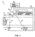
    • Figure 1 is a schematic representation showing an apparatus for determining fluid flow in a pipe.
    • Figure 2 is a schematic representation showing the geometric parameters associated with the apparatus for determining fluid flow in a pipe.
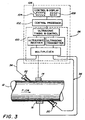
    • Figure 3 is a schematic representation showing the signal processing means of the apparatus for determining fluid flow in a pipe.
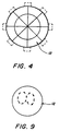
    • Figure 4 is a schematic representation of the apparatus for determining fluid flow in a pipe having a four ultrasound paths.
    • Figure 5 is a schematic representation shoving an apparatus for determining fluid flow in a pipe using a bounce path.
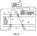
    • Figure 6 is a schematic representation of an apparatus for determining fluid flow using transducers disposed below the pipe's surface.
    • Figure 7 is a schematic representation showing an apparatus for determining the axial transverse velocity profile.
    • Figure 8 is a schematic representation of an apparatus for determining fluid flow in a pipe using three transducers.
    • Figure 9 is an image of a transverse velocity profile of a pipe.
    • DESCRIPTION OF THE PREFERRED EMBODIMENT
    • Referring now to the drawings wherein like reference numerals refer to similar or identical parts throughout the several views, and more specifically to figures 1 and 2 thereof, there is shown an apparatus 10 for determining the flow rate of a fluid 11 in a pipe 12. The apparatus 10 comprises means for providing acoustic energy on a diagonal path 24 through the fluid 11. The diagonal providing means is in acoustic contact with and preferably disposed on the pipe 12. The apparatus 10 also comprises means for providing acoustic energy on a diametrical path 18 through the fluid 11. The diametrical providing means is in acoustic contact with and preferably disposed on the pipe 12. The apparatus 10 is also comprised of means for determining the flow of fluid 11 in the pipe 12 based on the acoustic energy of the diagonal providing means and the acoustic energy of the diametrical providing means. In one embodiment, the diagonal providing means is fixedly disposed on the pipe 12. In another embodiment, the diametrical providing means provides acoustic energy emitted in both directions on the diametrical path 18.
    • Referring to figure 1, the diametrical providing means is preferably comprised of a first transducer 14 and a second transducer 16 located at diametrically opposed upstream and downstream positions relative to one another. The first transducer 14 and second transducer 16 are preferably adapted to alternatively function as transmitter and receiver so as to cause ultrasonic signals to travel through the fluid 11 alternatively in upstream and downstream directions along a diametric path 18 between the first transducer 14 and the second transducer 16.
    • The diagonal providing means is preferably a third transducer 20 and a fourth transducer 22 located at diagonally opposed positions about the pipe 12. The third transducer 20 and the forth transducer 22 are preferably adapted to alternatively function as a transmitter and receiver so as to cause ultrasonic signals to travel through the fluid 11 along a diagonal path 24. The diametric path 18 is adjacent to the diagonal path 24 so that the transducers are essentially sampling the same portion of fluid 11.
    • The determining means preferably comprises signal processing means 26 for determining the flow of fluid 11 in the pipe 12 based on the transmission speed of ultrasonic signals transmitted between the first and second transducers 14, 16 and the third and fourth transducers 20, 22, respectively.
    • Preferably, the transducers 14, 16, 20 and 22 are mounted on the outside of the pipe 12 and thus do not disturb the fluid flow therein. The coupling between the third and fourth transducers 20, 22 and the pipe 12 is preferably accomplished by mounting the third and fourth transducers 20, 22 onto a coupling wedge 28 which can be comprised of vespal or lucite, for example. The first and second transducers 14, 16 are mounted on a pad 30, which can also be comprised of vespal or lucite. The coupling between the wedges 28 and pads 30 and the pipe 12 can be enhanced by providing a layer 32, such as silicon rubber. The layer 32 helps in preventing disruption or dispersion of the ultrasonic signals as they travel from their respective wedge 28 or pad 30 to the pipe 12. Preferably, the signal processing means 26 includes means for measuring the transit time of ultrasonic signals transmitted between the first and second transducers 14, 16 and the transit time between ultrasonic signal transmitted between the third and fourth transducers 20, 22, respectively.
    • In a preferred embodiment, there is a plurality of diagonal sets of transducers for transmitting ultrasonic signals through the fluid 11 along a plurality of diagonal paths 24 and an equal number of diametrical sets of transducers for transmitting ultrasonic signal through the fluid 11 along a plurality of diametrical paths 18. Figure 4 shows a cross section through the axis of the pipe 12 showing a four path system. Since figure 4 is a cross sectional view, the transducers shown can be either diagonal sets or diametrical sets. Likewise, the four paths shown can be either diametrical paths 18 or diagonal paths 24.
    • It should be noted that in figure 2 and the specification, the following nomenclature is used:
    • Q = total flow in pipe 12 (cubic inches/sec)
    • Π = Pi = 3.141593
    • ID = Inside diameter of pipe 12 (inches)
    • PF = Hydraulic profile factor = ratio of average velocity over whole pipe 12 to average velocity along diameter
    • c f = velocity of sound in fluid 11 (inches/sec)
    • ϕ f = angle of acoustic path in fluid 11
    • td1 = transit time along diametrical path 18 from transducer 14 to transducer 16
    • td2 = transit time along diametrical path 18 from transducer 16 to transducer 14
    • Δtd = difference in time along diametrical path 18 (seconds)
    • that is Δtd = td1 - td2
    • tc1 is transit time along diagonal path 24 from transducer 20 to transducer 22
    • tc2 is transit time along diagonal cross path 24 from transducer 22 to transducer 20
    • Δtc = difference in time along diagonal cross path 24 (seconds)
    • that is Δtc = tc1 - tc2
    • cw = velocity of sound in transducer wedge 28 and pad 30 (inches/sec)
    • ϕwo = mechanical wedge 28 angle
    • aw = height of wedge (inches)
    • awc = height of pad 30
    • ap = wall thickness of pipe 12 (inches)
    • ϕp = acoustic path angle in pipe 12
    • ϕw = acoustic path angle in wedge 28
    • cpt = velocity of transverse wave in pipe 12 (inches/sec)
    • cp1 = velocity of longitudinal wave in pipe 12 (inches/sec)
    • td = average transit time along diametrical path 18 (seconds)
    • that is td = (td1 + td2)/2
    • tc = average transit time along diagonal path 24 (seconds)
    • that is tc = (tc1 + tc2)/2
    • y is the distance between centers of transducers 14, 16
    • yo is the calculated value of y to be used in initial set up
    • temp = Temperature in degrees F
    • press = Pressure in psi absolute
    • press = pressure gauge + 14.7
    • tr, vt, dvdp, tc are parameters used in the calculation of velocity of sound in water
    • Acpl, Bcpl, Acpt, Bcpt are constants used in calculation of velocity of sound in pipe (dependent on pipe material)
    • Acw, Bcw, Ccw are constants used in calculation of velocity of sound in wedge (dependent on wedge material)
    • The flow rate Q of the fluid is calculated by: Q = (π · ID2 · PF/4) · va since, va = vd/Sinϕ f - vc/Tanϕ f and, vd = (c f 2 · Cosϕ f /2 · ID) · (Δtd) vc = (c f 2/2 · ID) · (Δtc) Thus, va = (c f 2/2 · ID · Tanϕ f ) · (Δtd - Δtc) substituting into the original equation, Q = (π · ID · PF · C f 2/8 · tanϕ f ) · (Δtd - Δtc)
    • For acoustic path-to-transmitter length ratios less than 16:1, ϕ f is calculated using Snells law relationship as follows: ϕ f = sin-1(c f sinϕw/cw)
    • For acoustic path-to-transmitter length ratios greater than 100:1, calculation of ϕ f is given by solution of the following simultaneous equations: td = 2 ·aw/Cosϕw·cw + 2·ap/Cosϕp·cpt + ID/Cosϕ f ·c f Sinϕ f /c f = Sinϕp/cpt (Snells law) Sinϕ f /c f = Sinϕw/cw (Snells law)
    • Ideally, the acoustic path-to-transmitter length ratio should be chosen to fall clearly into one of these regions. Alternatively, if this cannot be achieved, then the fourth transducer is moved axially along the pipe 12 until the position is found at which the signal transferred from the third transducer 20 to the fourth transducer 22 is a maximum. At this point, either set of the above equations can be used.
    • If y is known ϕ f is given by solution of the following set of equations: y = 2·aw·Tanϕw+2·ap·Tanϕp+ID·Tanϕ f Sinϕ f /c f = Sinϕp/cpt Snells law and Sinϕ f /c f = Sinϕw/cw Snells law
    • Calculation of y o
    • Sinϕ f = c f ·Sinϕwo/cw Snells law Sinϕp = cpt·Sinϕwo/cw Snells law yo=2·aw·Tanϕw+2·ap·Tanϕp+ID·Tanϕ f Calculation of c f is given by solution of equation: tc = ID/c f + 2·ap/cp1 + 2·awc/cw
    • The speed of sound values are dependent on temperature. td is measured with the first transducer 14 and the second transducer 16 through the diametric path 18 therebetween. Cpt, Cpi and Cw are determined by the following equations. cpt = Acpt*(1+Bcpt*temp) cp1 = Acpl*(1+Bcpl*temp) cw = Acw*(1+Bcw*temp+Ccw*temp^2)
    • ID, ap and awc are known (measured) from the specific application of the apparatus.
    • With c f known by solution of Equation (5), tc measured with the third transducer 20 and the fourth transducer 22 through the diagonal path 24 therebetween, and aw, cw and ap, cpt and ID known, solution of, for example, the three Equations (2)-(4) determine the three unknowns ϕw, ϕp and ϕ f in these equations. Consequently, Q can then be determined since every variable in Equation (1) is now known.
      For instance, for carbon steel pipe 12
    • Acpl=2356000
    • Bcpl=.0000735
    • Acpt=127700
    • Bcpt=.0000925
    • For vespal wedges 28
      • Acw=98299
      • Bcw=.0003960
      • Ccw=2.08E-7
      To calculate c f in water temperatures>200°F tr=temp-175.1 vt=5290.52-.15302*tr-.0138265*tr^2+3.326E-6 *tr^3+3.11042*tr^4-5.1131E-11*tr^5 dvdp=756.78/(725-temp)+6.3846-.034241*(725-temp) +7.4075-5*(725-temp)^2-5.666E-8*(725-temp)^3 vtp=vt-(4437-press)*dvdp*.02253 c f =vtp*12 To calculate c f at water temperatures<200°F tc=(temp-32)/1.8 c f =100/2.54*(1402.49+5.0511*tc-.05693*tc^2+2.7633E-4* tc^3-&.1558E-7tc^4)
    • The above equations assume that the wedges 28, pipe 12 and fluid 11 are all at the same temperature. When the temperature of the fluid 11 is different from that of ambient temperature, it is desirable to provide insulation or other means to insure that the temperature is uniform or to modify the equations given above to correct for these differences. For small gradients it is sufficient to assign different temperatures to the wedges and pipe thus temp(pipe) = temp(fluid) - Δtp temp(wedge) = temp(fluid) - Δtw temp(cross wedge) = temp(fluid) - Δtwc where
    • Δtw is the difference between the fluid temperature and the average temperature of the wedge
    • Δtwc is the difference between the fluid temperature and the average temperature of the cross wedge or pad
    • Δtp is the difference between the fluid temperature and the average temperature of the pipe
    • For large gradients, it is desirable to have detailed knowledge of the temperature distribution in the pipe and wedge and to use ray tracing techniques as practiced in the design of optical instruments to calculate the times spent in the wedge and pipe and contribution of the pipe and wedge to the y displacement.
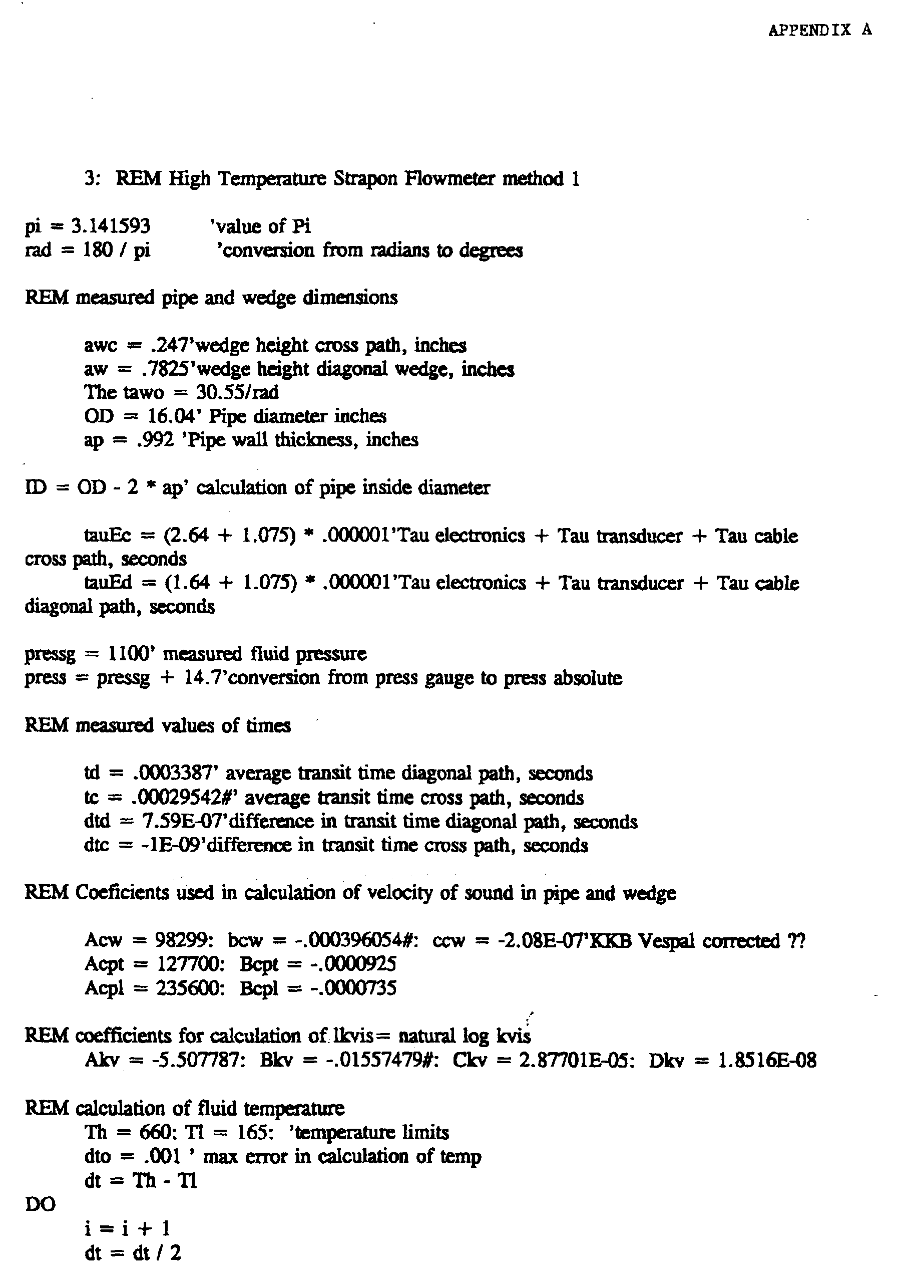
    • If the temperature of the fluid is not known, as shown in the "REM Calculation of Fluid Temperature" section of the program of the Appendix, c f as well as the temperature of the water can be arrived at in an iterative loop technique that essentially picks a temperature value of the water based on the known temperature limits of the water, uses this temperature value to arrive at values of c f cwc and cp1, and then uses the values of c f , cwc and cp1 in equation (5) to arrive at a calculated value of tc. The actual measured value of tc is then compared with the calculated value of tc.
    • If the calculated value of tc does not match the measured value of tc, different temperature values are sequentially picked in the program and the loop is reiterated until the calculated value of tc matches the measured value of tc. The picked temperature and the calculated value of c f during the last loop are then known to be the actual values of temperature and c f .
    • In this manner, both the speed of sound in the fluid, c f , and the temperature of the fluid 11 flowing in the pipe 12 can be determined by mounting a pair of ultrasonic transducers in a diametrical opposed relation on the pipe 12 and using signal processing means to determine a measured value of tc.
    • In the operation of the invention, the transducers 14, 16, 20 and 22 are preferably strap-on types. The strap-on transducer assembly contains a piezoelectric transducer, a coupling wedge 28 or pad 30 and a protective cover. The transducer converts the electrical energy to ultrasonic energy which the wedge 28 and pads 30 directs into the pipe 12 at the proper angle. The protective cover provides a fitting for the transducer cable 36 conduit as well as protection of the transducer.
    • After precisely locating the transducer on the surface of the pipe 12, the transducer wedge is coupled acoustically to the pipe wall and then secured with strapping material, magnetic holders, or welded brackets.
    • The transducer signal cable is a twinax twisted pair with a shield with an appropriate jacket for underwater or above ground use as required. It is connected to the transducer at one end and to the signal processing means 26 at the other, normally without splices.
    • The signal processing means 26 is comprised of three major functional units. These are the Acoustic Processing Unit 100 (APU), the Central Processing Unit 102 (CPU), and the Control and Display Panel 104 (CDP). Figure 3 provides a functional diagram of these electronics.
    • The APU 100 controls the transmission and reception of ultrasonic signals to and from the transducers. Electronic pulses are generated and sent to the transducers, where the energy is converted into ultrasound and directed upstream or downstream in directly into the pipe depending on which transducer is transmitting, converted back into electronic pulses, and received. Transmit times of pulses are measured with a 100 Mhz clock, alternately upstream and downstream, every 4 ms to assure that data is essentially simultaneous for upstream and downstream transit times. These time measurements are stored and then sent to the central processing unit 102 for mathematical manipulation.
    • The APU 100 typically is equipped with two transmitter/receiver boards which control a total of four ultrasonic diametrical paths 18. Additionally, there are two transmitter/receiver boards to control four ultrasonic diagonal paths 24.
    • The CPU 102 consists of a 286 microprocessor and I/O with software suited specifically to the needs of the application. The CPU 102 provides a number of important functions, including processing the transit time measurements from the APU 100. Flow totalizers are also updated according to Euler's equation. At the same time as high speed calculations are being processed, the displays are updated, electronic checks are being made of the entire APU 100 circuitry, user keypad commands are followed, and outputs are updated.
    • The CDP 104 functions as the user interface. A full screen display 106 provides readouts of flowrates, flow totals, diagnostics, set-up parameters, and pertinent performance characteristics. A numeric keypad 108 allows the operator to select desired display screens without consulting a programmer's handbook and without need of attaching a separate computer.
    • Listed below in Tables 1 through 3 are summaries of the calculated parameters for two verification sites. These verification sites were the Alden Research Laboratories (ARL) and the Tennessee Valley Authority (TVA) Sequoyah Nuclear Power Plant. The ARL test used a 16in OD pipe with fluid temperature at approximately 105° Fahrenheit. (The data presented below are documented by ARL which is an NIST approved facility). The TVA test used a 32in OD pipe with fluid temperature at approximately 435° Fahrenheit. Independent error analysis determined its accuracy to be ±0.9% of measured flow.
      Flow Calculation at ARL 12/18/91
      Conditions:
      ID = 15.028in (Direct Measurement)
      pressure = 50 psi
      ap = .495in (Direct Measurement)
      temp = 105.32° (ARL Reference)
      Q = 18,390 gpm (ARL Reference)
      cw = 92,170 in/sec (Direct Measurement)
      ϕwo = 30.550
      cp1 = 233,774in/sec (Curve fit from Published values)
      awc = .25 in
      cpt = 125,454in/sec (Curve fit from Published values)
      aw td1 = .586 in = 291.86 µsec
      LEFM Measured values:
      td1 = 291.86 µsec
      td2 = 290.66 µsec
      td1 = 241.45 µsec
      tc2 = 241.45 µsec
      Δtd = 1218 ns
      tc = 241.45 µsec
      Δtc = -4 ns
      td c f = 291.26 µsec = 60,260in/sec
      LEFM Calculated values:
      c f = 60,260in/sec
      temp = 105°
      Q = 18,488 gpm
      ϕ f = 19.4°
      ϕw = 30.53°
      ϕp = 43.75°
      y = 6.92 in
      yo (calculated) = 6.92 in
      Flow Calculation at ARL 12/18/91
      Conditions:
      ID = 15.028in (Direct Measurement)
      ap = .495 in (Direct Measurement)
      temp = 105.19° (ARL Reference)
      Q = 13,430 gpm (ARL Reference)
      cw = 92,170in/sec (Direct Measurement)
      cp1 = 233,774in/sec (Curve fit from Published values)
      cpt td = 125,454in/sec (Curve fit from Published values) = 291.26 µsec
      LEFM Measured values:
      td = 291.26 µsec
      tc = 241.45 µsec
      Δtd = 890 ns
      Δtc c f = -3 ns = 60,260 in/sec
      LEFM Calculated values:
      c f = 60,260 in/sec
      temp = 105°
      Q = 13,480 gpm
      ϕ f = 19.4°
      Flow Calculation at TVA Sequoyah 2/6/92
      Conditions:
      ID = 29.92 in (Indirect Measurement)
      ap = 1.194in (Direct Measurement)
      temp = 428° (TVA RTD measurement)
      cw = 82,750in/sec (Direct Measurement and Curve Fit)
      cp1 = 223,466in/sec (Curve fit from Published values)
      cpt td = 124,322in/sec (Curve fit from Published values) = 670.32 µsec
      LEFM Measured values:
      td = 670.32 µsec
      tc = 612.22 µsec
      Δtd = 1413 ns
      Δtc c f = 1 ns = 50,386 in/sec
      LEFM Calculated values:
      c f = 50,386 in/sec
      temp = 428.8°
      Q = 13.518 Mlbs/hr
      ϕ f = 19.4°
    • In an alternative embodiment, as shown in figure 5, the third transducer 20 and the fourth transducer 22 are aligned with each other such that acoustic energy transmitted by the third transducer 20 follows a diagonal path to the fourth transducer 22 which is formed by reflection of the acoustic energy off of the pipe 12. This configuration of the apparatus 10, as shown in figure 5, is otherwise known as the bounce path configuration. The first transducer 14 and the second transducer 16 which create the diametrical path 18, are disposed adjacent the diagonal path 24 that forms the bounce path, either between the third transducer 20 and fourth transducer 22 or outside the third transducer 20 or fourth transducer 22. The equations described above are also applicable to determine flow in the bounce path configuration of figure 5. An example of such a configuration is the following:
    • Q = 472 gpm
    • ID = 27.25 inches
    • PF = 1.00
    • c f = 47,275.7 inches
    • ϕp = 18.35°
    • td1 = 385.180 µsec
    • td2 = 385.000 µsec
    • Δtd = 180 nsec
    • tc1 = 179.008 µsec
    • tc2 = 179.000 µsec
    • Δtc = 8 nsec
    • cw = 92,046.09 inches/sec
    • ϕwo = 38.52°
    • aw = 0.642 inches
    • awc = 0.250 inches
    • ap = 0.360 inches
    • ϕp = 57.74°
    • ϕw = 37.80°
    • cpt = 126,989.7 inches/sec
    • cp1 = 231,992.8
    • td = 385.090 µsec
    • tc = 179.004 µsec
    • y = 7.5
    • yo = 7.423
    • temp = 74°F
    • pressure = 775 psi
    • Conditions
    • Pipe ID = 7.9529 inches
    • ap = 0.3605 inches
    • temp = 74°
    • cp1 = 231,945.8 in/sec (from tables)
    • cpt = 126,956.3 in/sec (from tables)
    • cw = 91,987.1 (direct measurement)
    • LEFM Measurements
    • td = 386 µsec
    • tc = 180 µsec
    • Δtd = 177 nsec
    • Δtc = 8 nsec
    • LEFM Calculated Values
    • c f = 47,001.3 in/sec. (ϕw = 37.18°)
    • Q = 468 gpm (ϕp = 56.51°)
    • ϕ f = 17.98°
    • In another alternative embodiment, as shown in figure 6, the pipe 12 has an outside surface 27 and an interior 29 and the first transducer 14 and second transducer 16 are disposed in the pipe 12 beneath the outside surface 27 such that acoustic energy transmitted by the first transducer 14 is introduced into the interior 29 of the pipe 12, an acoustic energy is received by the second transducer 16 directly from the interior 29 of the pipe 12 as shown in figure 6. The diametrical path 18 is thus formed without having acoustic energy, preferably ultrasonic energy, passing directly through the pipe 12. Preferably, the third transducer 20 and fourth transducer 22 are disposed in the pipe 12 beneath the outside surface 27 such that acoustic energy transmitted by the third transducer 20 is introduced directly into the interior 29 of the pipe, and acoustic energy is received by the fourth transducer 22 directly from the interior 29 of the pipe 12 after it has taken a diagonal path 24 therethrough. Of course, the third transducer 20 and fourth transducer 22 can be mounted on the outside 27 of the pipe 12 as described above, or, the various transducers can be mounted on or below the outside surface 27 depending on the design choice such that only one transducer, three transducers, etc. can be on or below the outside surface 27. The algorithm associated with calculation of the flow and other relevant factors for the embodiment shown in figure 6 can be found in Caldon technical report DS-112-991 (incorporated by reference) with respect to a single pair of transducers forming a diagonal ultrasonic path. For the pair of transducers forming the diametrical ultrasonic path =90°, Cos =1 yielding the transverse flow velocity V. For a 4-path configuration, see Caldon technical report DS-116-392 (incorporated by reference). The placement of the transducers beneath the outside surface 27 of the pipe 12 is well known. See Caldon technical report installation procedure SP1041 Rev. C, incorporated by reference.
    • The present invention also pertains to an apparatus for creating a transverse velocity profile of fluid flowing in a pipe 12. The apparatus comprises means for obtaining a transverse velocity of fluid in a plurality of different locations in the pipe 12 by introducing energy into the pipe 12 and analyzing the energy. Preferably, the obtaining means includes means for providing acoustic energy along a plurality of diametrical paths in the pipe 12, all of which are in a common cross section of the pipe 12, and producing an information signal corresponding to the transverse velocity of the plurality of different locations. The providing means can be a plurality of transducers which create a plurality of diametrical paths 18 in the pipe 12 as shown in figure 4. Each diametrical path 18 identifies the transverse velocity component associated with a corresponding location in the pipe 12. The transverse velocity corresponding to each diametrical path 18 can be determined by Equation (0).
    • The apparatus is also comprised of means for forming a transverse velocity profile from the transverse velocities at the plurality of different locations. The forming means is in communication with the obtaining means. Preferably, the forming means includes signal processing means 26. The signal processing means 26 receives the information signal and determines the transverse velocity associated with each location. Each pair of transducers which form a diametrical path 18 can be connected to signal processing means 26 as described above to calculate the transverse velocity for the corresponding diametrical path 18. Preferably, the more diametrical paths 18 in a given cross section of the pipe, the more accurate the transverse velocity flow profile will be.
    • Preferably, the forming means includes a monitor in which the transverse velocity of the locations are displayed together to show the transverse velocity profile. An example of a display that would appear on a monitor is shown in figure 9 which shows the rotational component both in the clockwise and counterclockwise direction cross section of the pipe 12. A ratio of VC:VD can be used to deduce the flow profile characteristic (see Weske, J. "Experimental Investigation of Velocity Distributions Downstream of Single Duct Bends," NACA-TN-1471, January 1948, incorporated by reference). The flow profile characteristic can be used to choose path(s) with the lowest diametrical to diagonal velocity ratio.
    • The present invention also pertains to an apparatus for determining transverse velocity of fluid in a pipe 12. The apparatus is comprised of means for actively testing the flowing fluid with energy and producing a test signal corresponding to the transverse velocity of the fluid. The testing means is in contact with the pipe 12. The apparatus 106 is also comprised of signal processing means 26 for determining the transverse velocity of the fluid based on the test signal. The signal processing means 26 is in communication with the transverse velocity testing means 106. As described above, the testing means is preferably a first transducer 14 and a second transducer 16 which are in contact with the pipe 12 such that they form a diametrical path 18. From Equation (0), the transverse velocity can be obtained with the signal processing means 108.
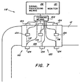
    • The present invention also pertains to a method for creating a velocity profile of fluid flowing through an axial length 110 of pipe 12 as shown in figure 7. The method comprises the steps of (a) measuring transverse velocity flow of the fluid at a first axial location 112 of the pipe 12 with energy introduced therein. Then, there is the step of (b) measuring transverse velocity flow of the fluid at a second axial location 114 of the pipe 12 with energy introduced therein. Preferably, after step (b), there is the step (c) of forming a profile of the transverse velocity of fluid flowing in the pipe 12 over the axial length 110 of the pipe from the transverse velocity measured at the first axial location 112 and second axial location 114. Preferably, before step (c), there is the step (d) of measuring the transverse velocity of fluid flowing in the pipe 12 at a plurality of additional different axial locations, such as axial location 116 with energy introduced to the pipe 12. After the step (d), there can be the step (e) of fixing a flow meter in contact with the pipe 12 at a desired axial location based on the transverse velocity flow thereat.
    • Also as shown in figure 7, there is an apparatus 118 for creating a velocity profile of fluid flowing through a pipe 12. The apparatus 118 is comprised of means 120 for obtaining transverse velocity flow information of fluid along an axial length 110 of the pipe 12 with energy introduced therein. The apparatus 118 is also comprised of means 122 for forming a transverse velocity profile along the axial length 110 of the pipe 12 from the transverse flow information. The forming means 122 is in communication with the obtaining means 120. Preferably, the obtaining means 120 can be a plurality of transducers 124 disposed in a removable housing, for instance, connected with velcro. The transducers 124 are disposed in the housing 126 such that each transducer 124 has a mate transducer 124, which together form a diametrical path. Individual sets of transducers provide their diametrical path information to the obtaining means 122, which is preferably signal processing means 26 as described above, to calculate the transverse flow. The forming means 122 can also include a monitor 121 which is connected to signal processing means 26 that displays the velocity profile along the axial length 110. A flow meter, for instance, comprised of first transducer 14, second transducer 16, third transducer 20 and fourth transducer 22, as shown in figure 1, can then be fixedly attached to the pipe 12 at a location where there is minimal transverse velocity flow, so that an accurate a reading as possible of the axial flow through the pipe 12 can be obtained.
    • The present invention is also an apparatus for measuring the temperature of a flowing fluid 11 in a pipe 12. The apparatus is comprised of means for actively testing the flowing fluid with energy and producing a test signal corresponding to the temperature of the fluid 11. The testing means is in contact with and preferably disposed on the outside of the pipe 12. The apparatus is also comprised of signal processing means 26 for determining the temperature of the fluid 11 based on the test signal.
    • Preferably, the testing means comprises a first transducer 14 for transmitting ultrasonic signals through the fluid 11 and a second transducer 16 for receiving ultrasonic signals transmitted by the first transducer 14. The second transducer 16 is disposed in an opposing relation with the first transducer 14 such that the ultrasonic signals transmitted by the first transducer 14 travel on a diametric path 18 with respect to the pipe 12 to the second transducer 16. Preferably, the testing means also includes means for measuring pressure of the fluid in the pipe 12, such as a pressure gauge or sensor. The pressure measuring means is in communication with the signal processing means 26 and the pipe 12. The signal processing means 53 preferably determines the temperature of the fluid in the pipe 12 based on the transmission speed of ultrasonic signals transmitted between the first and second transducers and the pressure of the fluid. Preferably, the signal processing means 26 identifies the average temperature of the fluid across the pipe 12 corresponding to the diametric path 18 between the first transducer 14 and second transducer 16. Preferably, to calculate the temperature, Equations 9-14 below can be used in the signal processing means 20, such as a computer. By being disposed on the outside of the pipe 12, the first and second transducers do not interfere with the flow of fluid 11 with the pipe. The temperature of the fluid 11 flowing in the pipe 12 can thus be determined without the apparatus penetrating the envelope defined by the inside diameter, ID, of the pipe 12.
    • The present invention is also an apparatus for measuring the speed of sound in a fluid 11 flowing in a pipe 12. The apparatus comprises means for testing the flowing fluid 11 and producing a test signal corresponding to the speed of sound of the fluid in the pipe. The testing means is in contact with and preferably disposed on the outside of the pipe 12. The apparatus also includes signal processing means 26 for determining the speed of sound of the fluid in the pipe based on the test signal. Preferably, the testing means is disposed in a gaseous environment on the outside of the pipe 12. Preferably, the testing means comprises a first transducer 14 for transmitting ultrasonic signals through the fluid 11 and a second transducer 16 for receiving ultrasonic signals transmitted by the first transducer 14. The second transducer 16 is disposed in an opposing relation with the first transducer 14 such that the ultrasonic signals transmitted by the first transducer 14 travel on a diametric path 18 with respect to the pipe 12 to the second transducer 16. The speed of sound can be determined by the signal processing means 26, such as a computer, with Equations (5), (7) and (8) and the necessary measured data.
    • The present invention also pertains to an apparatus 10 for characterizing fluid properties in a pipe 12. The apparatus 10 comprises first means for measuring sound velocity in the fluid and producing a first signal corresponding to the sound velocity. The first measuring means is in communication with the fluid. The apparatus 10 is also comprised of second means for measuring at least one state variable of the fluid and providing a second signal corresponding to the state variable measured. The second means is in communication with the fluid in the pipe. Additionally, the apparatus is comprised of signal processing means 26 in communication with the first and second measuring means for determining fluid properties. As shown in figure 1, the second measuring means preferably includes means for measuring pressure of the fluid. The pressure measuring means is connected with the signal processing means 26. The pressure measuring means can be a pressure sensor in communication with the fluid. The first means can include a first transducer 14 and a second transducer 16 in contact with the pipe such that first transducer 14 transmits acoustic energy in a diametric path 18 to the second transducer 16. Each transducer is in communication with the signal processing means 26.
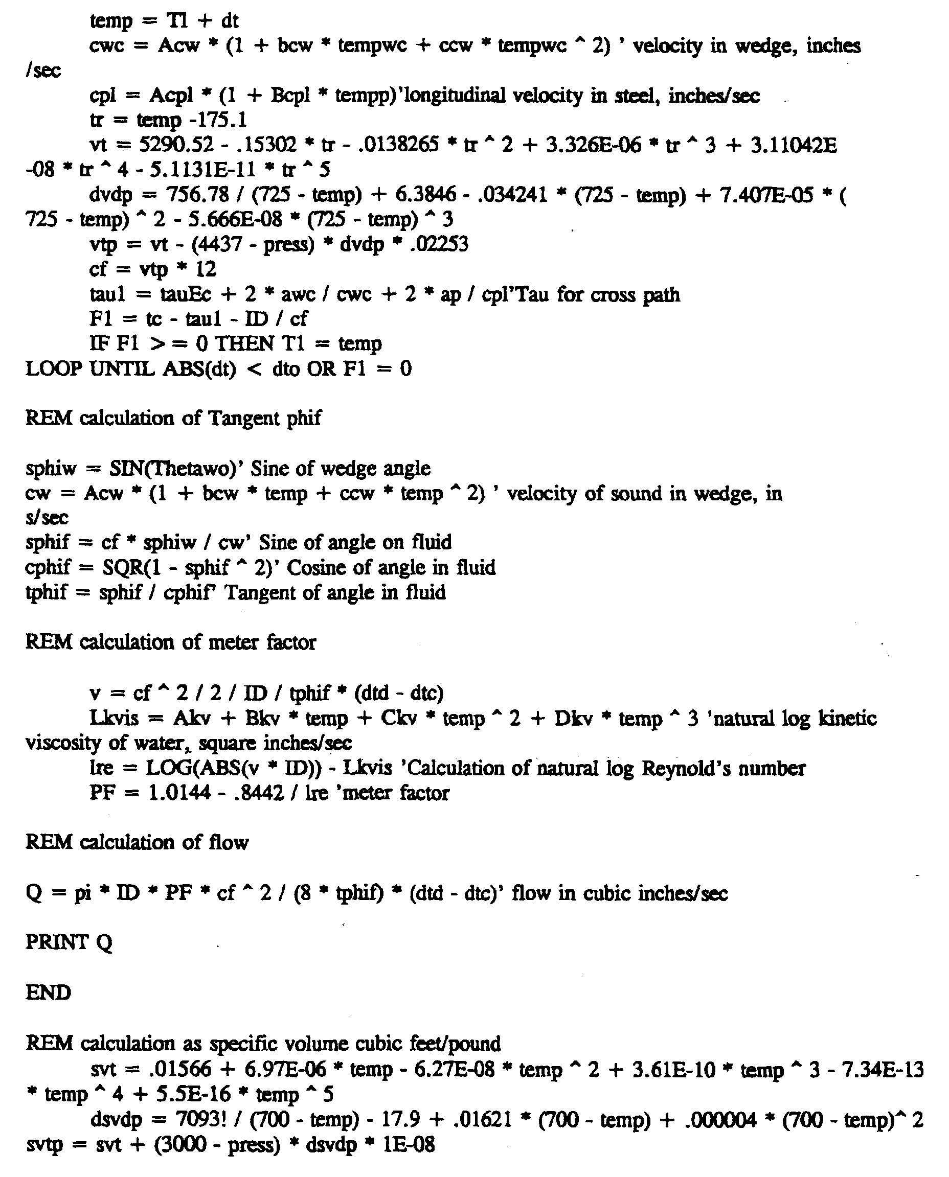
    • In this embodiment, preferably, the signal processing means 26 also determines specific volume of the fluid. The specific volume can be determined from the "REM calculation" as specific volume cubic feet/pound" in Appendix A. For this calculation, the pressure is independently measured with a pressure gauge and the temperature is calculated from the speed of sound, as described above. Additionally, the signal processing means 24 can determine Reynolds number for the fluid in the pipe from the specific volume and viscosity and consequently PF. It does this in the following way. The determination of the kinematic viscosity (kvis), the profile factor PF and the Reynolds number can be obtained from "REM calculation of meter factor" in Appendix A, where L represents log. 
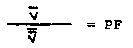
The profile correction factor, PF, relates to axial velocity averaged along the acoustic path between the diagonal transducers, v, with the axial velocity average across the cross sectional area of the flow, v. This is expressed as:
      Figure 00270001
    • The PF will vary depending on three factors. These are:
    • (1) Average fluid velocity, v.
    • (2) Fluid density and viscosity, ρ and µ, respectively.
    • (3) Cross section dimensions (i.e. ID).
    • The Reynolds number combines the hydraulic effect of the above 3 factors into one number. The Reynolds number, Re, can be used to determine an expression for the velocity profile (Nikuradse, J. "Laws of Turbulent Flow in Smooth Pipes," NASA TT F-10, 359, October 1966; Reichardt, H., "Vollständige Darstellung der turbelenten Geskhwindigkeitsverteilung in glatten Leitungen" ZAMM 31, 208-219 (1951), incorporated by reference) and thus the PF may be determined from knowledge of the Reynolds number.
    • The LEFM first calculates the kinematic viscosity using the curve fit of the published values for water vs. temperature.
      where: υ = Kinematic viscosity = µ/ρ = absolute viscosity/density
    • Then, the Reynolds number is calculated: Re = Reynolds number = Dv
    • The PF is then calculated using published data (i.e. Reichardt and Nikuradse) that express the velocity profile as a function of Reynolds number.
    • In the apparatus 10, with temperature measuring means, the signal processing means 24 preferably identifies when a boundary between fluid of a first material and fluid of a second material passes through the pipe at the diametrical path. The temperature measuring means can be, for instance, a thermal couple in contact with the pipe 12 or the fluid. Since there is independent identification of temperature and pressure, and with an essentially constant temperature and pressure, a change in specific volume determined by the first and second transducers and signal processing means 26 indicates a change in material in the pipe 12. Knowledge of the pressure, temperature and Sound velocity can be used to distinguish fluids which have sound velocities distinct from each other. Typically, fluid with sound velocities that differ by .5% at a given temperature and pressure are easily distinguished. Likewise, with knowledge of the pressure and calculated temperature, the specific heat content of water and water density can be determined from a curve fit of published data vs. temperature and pressure. Fluid enthalpy can be determined using the fluid density and specific heat content.
    • Another embodiment requires only three transducers to form a diagonal and a diametrical path, as shown in figure 8. Second transducer 16 and fourth transducer 22 are the same as described above. In place of first transducer 14 and third transducer 20 is double transducer 23. On a first face 25 forming a 45° angle with the surface 27 is disposed piezoelectric 37 which emits ultrasonic energy. The ultrasonic energy is incident upon the double transducer 23-pipe 12 interface where a portion of the energy is refracted therethrough ultimately to third transducer 22, and a portion of the energy is reflected to free face 33. Free face 33 forms a 22.5° angle with the outer surface 27 of the pipe 12. The reflected energy from the double transducer 23-pipe 12 interface is again reflected by free face 33 such that it forms a right angle with the outer surface of the pipe 12 and is transmitted therethrough to second transducer 16.
    • Although the invention has been described in detail in the foregoing embodiments for the purpose of illustration, it is to be understood that such detail is solely for that purpose and that variations can be made therein by those skilled in the art without departing from the spirit and scope of the invention except as it may be described by the following claims.
      Figure 00310001
      Figure 00320001

    Claims (18)

    1. An apparatus (10) for measuring the temperature of a flowing fluid (11) in a pipe (12) characterized by:
      means (14, 16) for actively testing the flowing fluid (11) with acoustic energy and producing a test signal corresponding to the temperature of the fluid (11), said testing means (14, 16) disposed on the outside of the pipe (12) and acoustic energy follows a path through the pipe wall; and
      signal processing means (26) for determining the temperature of the fluid (11) based on the test signal, said testing means (14, 16) in communication with said signal processing means (26).
    2. An apparatus (10) as described in claim 1 characterized by the testing means (14, 16) comprising:
      a first transducer (14) for transmitting acoustic signals through the fluid (11), said first transducer (14) in acoustic contact with said pipe (12); and
      a second transducer (16) for receiving the acoustic signals transmitted by the first transducer (14), said second transducer (16) disposed in an opposing relationship with said first transducer (14) such that the acoustic signals transmitted by the first transducer (14) travel on a substantially diametric path (18) with respect to the pipe (12) to the second transducer (16).
    3. An apparatus (10) for creating a transverse velocity profile of fluid flowing in a pipe (12) characterized by:
      means (14, 16) for obtaining the transverse velocity of the fluid (11) at a plurality of different locations by introducing acoustic energy into the pipe (12) and analyzing the energy in the pipe, said obtaining means (14, 16) disposed on the outside of the pipe (12) and acoustic energy follows a path through the pipe wall; and
      means (26) for forming the transverse velocity profile from the transverse velocity at the plurality of different locations, said forming means in communication with said obtaining means (14, 16).
    4. An apparatus (10) as described in claim 3 characterized by the obtaining means (14, 16) including means (14, 16) for providing acoustic energy along a plurality of diametrical paths in the pipe, all of which are in a cross section of the pipe (12) and producing an information signal corresponding to the transverse velocity of the plurality of different locations; and signal processing means (26) for receiving the information signal and determining the transverse velocity associated with each location.
    5. An apparatus (10) as described in claim 4 characterized by the forming means (26) including a monitor (108) in which the transverse velocity of the locations are displayed together depicting the transverse velocity profile.
    6. An apparatus (10) for determining the transverse velocity of fluid (11) in a pipe (12) characterized by:
      means (14, 16) for actively testing the flowing fluid with acoustic energy and producing a test signal corresponding to the temperature of the fluid, said testing means disposed on the outside of the pipe (12) and acoustic energy follows a path through the pipe wall; and
      signal processing means (26) for determining the temperature of the fluid based on the test signal, said testing means in communication with said signal processing means.
    7. A method for creating a velocity profile of fluid (11) flowing through an axial length of pipe (12) characterized by the steps of (a) measuring transverse velocity flow of the fluid at a first axial location of the pipe (12) with acoustic energy introduced therein; and (b) measuring transverse velocity flow of the fluid (11) at a second axial location of the pipe (12) with acoustic energy introduced therein.
    8. A method as described in claim 7 characterized by after step (b), the step of (c) forming a profile of the transverse velocity of fluid flowing in the pipe (12) over the axial length of the pipe (12) from the transverse velocity measured at the fist and second axial locations.
    9. A method as described in claim 8 characterized by before step (c), the step of (d) measuring the transverse velocity of fluid (11) flowing in the pipe (12) at a plurality of additional different axial locations with energy introduced into the pipe (12).
    10. A method as described in claim 9 characterized by after the step (e), the step (f) of fixing a flow meter (10) in contact with the pipe (12) at a desired axial location based on the transverse velocity flow thereat.
    11. An apparatus (10) for creating a velocity image profile of fluid (11) flowing through a pipe (12) characterized by:
      means (14, 16) for obtaining transverse velocity flow information of fluid (11) along an axial length of the pipe (12) with acoustic energy introduced therein, said obtaining means disposed on the outside of the pipe (12) and acoustic energy follows a path through the pipe wall; and
      means (26) for forming the transverse velocity profile along the axial length of the pipe (12) from the transverse flow information, said forming means (26) in communication with the obtaining means (14, 16).
    12. An apparatus (10) as described in claim 1 characterized by means for detecting pressure of the fluid (11) in the pipe (12), said detecting means in communication with said signal processing means (26).
    13. An apparatus (10) for characterizing fluid (11) properties in a pipe (12) characterized by:
      first means (14, 16) for measuring sound velocity in the fluid (11) and producing a first signal corresponding to the sound velocity, said first measuring means (14, 16) disposed on the outside of the pipe (12) and acoustic energy follows a path through the pipe wall;
      second means for measuring at least one state variable of the fluid (11) and providing a second signal corresponding to the state variable measured, said second means disposed on the outside of the pipe (12) and acoustic energy follows a path through the pipe wall into the fluid (11); and
      signal processing means (26) in communication with the first and second measuring means (14, 16) for identifying fluid properties.
    14. An apparatus (10) as described in claim 13 characterized by the second measuring means including means for measuring temperature or means for measuring pressure of the fluid.
    15. An apparatus (10) as described in claim 14 characterized by said signal processing means (26) also determines specific volume of the fluid.
    16. An apparatus (10) as described in claim 15 characterized by the signal processing means (26) determining specific volume and viscosity of the fluid (11).
    17. An apparatus (10) as described in claim 16 characterized by said signal processing means (26) identifying when a boundary between fluid (11) of a first material and fluid (11) of a second material passes through the pipe (12) at the diametrical path (18).
    18. An apparatus (10) as described in claim 17 characterized by the signal processing means (26) determining Reynolds number for the fluid (11) from the specific volume of the fluid (11) and the viscosity and calculates a profile factor.
    EP00122251A 1992-10-06 1993-10-05 Apparatus for determining fluid flow Withdrawn EP1094305A3 (en)

    Applications Claiming Priority (3)

    Application Number Priority Date Filing Date Title
    US95741192A 1992-10-06 1992-10-06
    US957411 1992-10-06
    EP9393307895A EP0605944A3 (en) 1992-10-06 1993-10-05 Apparatus for determining fluid flow.

    Related Parent Applications (1)

    Application Number Title Priority Date Filing Date
    EP9393307895A Division EP0605944A3 (en) 1992-10-06 1993-10-05 Apparatus for determining fluid flow.

    Publications (2)

    Publication Number Publication Date
    EP1094305A2 true EP1094305A2 (en) 2001-04-25
    EP1094305A3 EP1094305A3 (en) 2002-04-10

    Family

    ID=25499532

    Family Applications (2)

    Application Number Title Priority Date Filing Date
    EP9393307895A Ceased EP0605944A3 (en) 1992-10-06 1993-10-05 Apparatus for determining fluid flow.
    EP00122251A Withdrawn EP1094305A3 (en) 1992-10-06 1993-10-05 Apparatus for determining fluid flow

    Family Applications Before (1)

    Application Number Title Priority Date Filing Date
    EP9393307895A Ceased EP0605944A3 (en) 1992-10-06 1993-10-05 Apparatus for determining fluid flow.

    Country Status (8)

    Country Link
    US (1) US5546813A (en)
    EP (2) EP0605944A3 (en)
    JP (1) JPH06201425A (en)
    KR (1) KR100208678B1 (en)
    CN (1) CN1083102C (en)
    CA (2) CA2107750C (en)
    MX (1) MX9306158A (en)
    TW (2) TW283763B (en)

    Cited By (7)

    * Cited by examiner, † Cited by third party
    Publication number Priority date Publication date Assignee Title
    EP1644833A2 (en) * 2003-07-14 2006-04-12 Daniel Industries, Inc., Method to snapshot and playback raw data in an ultrasonic meter
    WO2006066982A1 (en) * 2004-12-21 2006-06-29 Robert Bosch Gmbh Ultrasonic flowmeter having a pressure sensor
    WO2007020113A1 (en) * 2005-08-16 2007-02-22 Robert Bosch Gmbh Ultrasonic measuring unit with integrated humidity analysis
    EP2072972A1 (en) 2007-12-21 2009-06-24 SICK Engineering GmbH Device for measuring the movement of a fluid in a pipe
    AT10959U3 (en) * 2009-09-03 2010-06-15 Avl List Gmbh ULTRASONIC GAS FLOW SENSOR AND METHOD FOR DETERMINING THE FLOW OF GASES
    WO2010091648A1 (en) * 2009-02-10 2010-08-19 Univerzita Karlova V Praze Ultrasonic probe for liquid temperature measurement
    WO2012084391A1 (en) * 2010-12-20 2012-06-28 Endress+Hauser Flowtec Ag Coupling element of an ultrasonic transducer for an ultrasonic flow meter

    Families Citing this family (85)

    * Cited by examiner, † Cited by third party
    Publication number Priority date Publication date Assignee Title
    JP3216769B2 (en) * 1995-03-20 2001-10-09 富士電機株式会社 Temperature and pressure compensation method for clamp-on type ultrasonic flowmeter
    NL1001719C2 (en) * 1995-11-22 1997-05-23 Krohne Altometer Method and device for the ultrasonic measurement of the velocity and flow rate of a medium in a pipeline.
    AU740625B2 (en) * 1995-12-28 2001-11-08 Ohio University Ultrasonic measuring system and method of operation
    US5719329B1 (en) * 1995-12-28 1999-11-16 Univ Ohio Ultrasonic measuring system and method of operation
    WO1998014774A1 (en) * 1996-10-04 1998-04-09 Dietrich Technology Holding Corp. Method of determining a setback
    DE19713526A1 (en) * 1997-04-01 1998-10-08 Elster Produktion Gmbh Device for ultrasonic flow measurement
    SE9701477L (en) * 1997-04-21 1998-10-05 Siemens Elema Ab Measuring device for simultaneous determination of flow of a flowing gas mixture and concentration of a specific gas in the gas mixture.
    AU739495B2 (en) * 1997-04-24 2001-10-11 Precision Farming Australia Pty Ltd Apparatus for monitoring the volume of a particulate or clumpy material
    AUPO643097A0 (en) * 1997-04-24 1997-05-22 Precision Farming Australia Pty Ltd Cotton flow sensor
    DE19717940C2 (en) * 1997-04-29 1999-04-15 Krohne Ag Ultrasonic flow measurement method
    US5913243A (en) * 1997-09-30 1999-06-15 General Electric Co. Ultrasonic transducer for nondestructive testing of generator field coils of dynamoelectric machines
    SE515156C2 (en) * 1998-03-25 2001-06-18 Thermo Measurement Ltd Method and apparatus for determining the flow rate of a medium flowing in a channel
    WO2000003207A1 (en) * 1998-07-10 2000-01-20 Panametrics, Inc. Guided mode flow measurement system
    US6488097B1 (en) 1999-01-08 2002-12-03 Pnm, Inc. Fire protection sprinkler head support
    WO2000046575A1 (en) * 1999-02-04 2000-08-10 Bechtel Bwxt Idaho, Llc Ultrasonic flow metering system
    AU7834000A (en) 1999-09-27 2001-04-30 Ohio University Determining gas and liquid flow rates in a multi-phase flow
    US6487916B1 (en) 2000-02-02 2002-12-03 Bechtel Bxwt Idaho, Llc Ultrasonic flow metering system
    US6404344B1 (en) * 2000-02-23 2002-06-11 Gyco, Inc. Method of compensating for erroneous reading in a mass flow meter
    US6971259B2 (en) * 2001-11-07 2005-12-06 Weatherford/Lamb, Inc. Fluid density measurement in pipes using acoustic pressures
    US7059172B2 (en) * 2001-11-07 2006-06-13 Weatherford/Lamb, Inc. Phase flow measurement in pipes using a density meter
    EP1444486A1 (en) * 2001-11-16 2004-08-11 WestfaliaSurge GmbH Method and device for determining the volumetric flow rate of milk flowing during a milking process
    DE10221771A1 (en) * 2002-05-15 2003-11-27 Flowtec Ag Ultrasonic transducer system is used to measure the flow rate of a fluid within a channel or duct based upon the propagation of the wave signal
    AU2003255235A1 (en) * 2002-08-08 2004-02-25 Cidra Corporation Apparatus and method for measuring multi-phase flows in pulp and paper industry applications
    DE10312034B3 (en) * 2003-03-06 2004-03-18 Krohne Ag Ultrasonic throughflow measurement involves ultrasonic signal transition time measurement between ultrasonic transducers for multiple immediately successive transitions of defined path in medium
    BRPI0508637B1 (en) * 2004-03-10 2017-10-10 Cidra Corporation METHOD AND APPARATUS FOR MEASURING PARAMETERS OF A STRATIFIED FLOW
    DE102004028215A1 (en) * 2004-06-09 2005-12-29 Robert Bosch Gmbh Offset ultrasound transducer assembly with reflection rejection
    US7962293B2 (en) * 2005-03-10 2011-06-14 Expro Meters, Inc. Apparatus and method for providing a stratification metric of a multiphase fluid flowing within a pipe
    CN1332183C (en) * 2005-08-10 2007-08-15 陈宇 Fluid flow rate detector
    US7152490B1 (en) 2005-08-15 2006-12-26 Daniel Measurement And Control, Inc. Methods for determining transducer delay time and transducer separation in ultrasonic flow meters
    JP2007051913A (en) * 2005-08-17 2007-03-01 Tokyo Keiso Co Ltd Correction method for ultrasonic flowmeter
    DE102005059062B4 (en) * 2005-12-08 2009-08-27 Continental Automotive Gmbh Apparatus for determining a mass flow
    DK2000784T4 (en) 2007-06-06 2022-03-14 Kamstrup As Ultrasonic flow meter with temperature compensation
    DE102007027391B3 (en) * 2007-06-11 2009-01-08 Forschungszentrum Dresden - Rossendorf E.V. Ultrasonic sensor for measuring local flow velocities in liquid melts
    DE102007030699A1 (en) 2007-06-30 2009-01-15 Endress + Hauser Flowtec Ag Measuring system for a medium flowing in a process line
    DE102007030690A1 (en) 2007-06-30 2009-05-07 Endress + Hauser Flowtec Ag Measuring system for a medium flowing in a process line
    DE102007030700A1 (en) 2007-06-30 2009-05-07 Endress + Hauser Flowtec Ag Measuring system for a medium flowing in a process line
    DE102007030691A1 (en) 2007-06-30 2009-01-02 Endress + Hauser Flowtec Ag Measuring system for a medium flowing in a process line
    JP2009068894A (en) * 2007-09-11 2009-04-02 Wada Engineering:Kk Ultrasonic flow meter
    WO2009071870A1 (en) * 2007-12-05 2009-06-11 Schlumberger Technology B.V. Ultrasonic clamp-on multiphase flowmeter
    CN101255791B (en) * 2008-04-09 2011-05-25 浙江大学 Apparatus for measuring flow of oil gas water multiphase flow
    US9140593B2 (en) * 2008-04-22 2015-09-22 Cameron International Corporation Smooth bore, chordal transit-time ultrasonic meter and method
    MX2010011216A (en) * 2008-04-22 2010-11-12 Cameron Int Corp Smooth bore, chordal transit-time ultrasonic meter and method.
    KR100894430B1 (en) * 2008-11-11 2009-04-22 시스템디엔디(주) Device and method for measuring fluid leakage rate of a valve using ultrasonic, acoustic and temperature detection system
    CN101419180B (en) * 2008-12-04 2012-02-22 天津大学 Conductive sensor for phase separation containing rate in two-phase stream and structure parameter optimizing method thereof
    US7942068B2 (en) * 2009-03-11 2011-05-17 Ge Infrastructure Sensing, Inc. Method and system for multi-path ultrasonic flow rate measurement
    WO2010146403A1 (en) * 2009-06-19 2010-12-23 Metricon Ilektronika-Metritika Sistimata E.P.E. Device for volume measuring and quality control of liquid fuel
    US7845240B1 (en) * 2009-07-24 2010-12-07 Elster NV/SA Device and method for determining a flow characteristic of a fluid in a conduit
    DE102009045020A1 (en) 2009-09-25 2011-03-31 Robert Bosch Gmbh Flow meter for use in a flowing fluid medium
    CN102183274B (en) * 2011-05-17 2012-05-23 重庆梅安森科技股份有限公司 Wide-range double-vortex flowmeter
    DE102011080365A1 (en) * 2011-08-03 2013-02-07 Endress + Hauser Flowtec Ag Method for determining the flow by means of ultrasound
    US8919207B2 (en) * 2012-01-10 2014-12-30 General Electric Company Flow measuring device and method using transmission paths having different angles
    WO2014021846A1 (en) * 2012-07-31 2014-02-06 Siemens Aktiengesellschaft Indirect transducer temperature measurement
    JP5934622B2 (en) * 2012-09-25 2016-06-15 愛知時計電機株式会社 Temperature measuring instrument, flow meter and temperature measuring method
    US9151649B2 (en) * 2012-10-19 2015-10-06 Daniel Measurement And Control, Inc. Ultrasonic flow metering system with an upstream pressure transducer
    ES2725534T3 (en) 2012-12-04 2019-09-24 Stephen J Horne Fluid flow detection and analysis device and system
    US9151651B2 (en) * 2013-01-14 2015-10-06 General Electric Company Apparatus and method for determining temperature
    JP2014178202A (en) * 2013-03-14 2014-09-25 Osaka Gas Co Ltd Ultrasonic flowmeter and method for measuring ultrasonic flow
    JP2015001507A (en) * 2013-06-18 2015-01-05 横河電機株式会社 Ultrasonic flow meter
    CN103499642A (en) * 2013-09-25 2014-01-08 北京化工大学 Method and device for measuring compression coefficient and expansion coefficient of material on line
    CN104864923A (en) * 2014-02-24 2015-08-26 通用电气公司 Circuit assemblies for transmitting and receiving ultrasonic signals as well as system and method adopting circuit assemblies
    US9746360B2 (en) 2014-03-13 2017-08-29 Siemens Energy, Inc. Nonintrusive performance measurement of a gas turbine engine in real time
    US9752959B2 (en) * 2014-03-13 2017-09-05 Siemens Energy, Inc. Nonintrusive transceiver and method for characterizing temperature and velocity fields in a gas turbine combustor
    JP6301696B2 (en) * 2014-03-25 2018-03-28 テルモ株式会社 Flow sensor, extracorporeal circulation apparatus provided with flow sensor, and control method thereof
    ZA201404072B (en) * 2014-06-03 2015-06-24 Csir Transducer
    US9889327B2 (en) 2014-06-27 2018-02-13 Flexhead Industries, Inc. Adjustable bracket and hub for flexible hose support
    JP6582368B2 (en) * 2014-07-23 2019-10-02 東京電力ホールディングス株式会社 Flow rate measuring device and flow rate measuring method
    CN104316119A (en) * 2014-07-25 2015-01-28 浙江苍南仪表厂 Ultrasonic measuring method and ultrasonic measuring device for double acoustic path gas flow
    JP6309405B2 (en) * 2014-09-05 2018-04-11 アズビル株式会社 Ultrasonic flow meter and flow rate measurement method
    CN104457871A (en) * 2014-10-27 2015-03-25 北京福星晓程电子科技股份有限公司 Flowmeter and fluid measurement method
    CN104501889B (en) * 2015-01-23 2018-05-01 中煤科工集团重庆研究院有限公司 Detection method based on cross-correlation Time-difference Ultrasonic Flow
    CN105444829A (en) * 2015-10-12 2016-03-30 无锡清杨机械制造有限公司 Ultrasonic flow measurer
    DE102016006244A1 (en) 2016-01-14 2017-07-20 Diehl Metering Gmbh Ultrasonic fluid meter and method for flow and / or volume determination of a flowing medium
    US10159213B2 (en) 2016-04-13 2018-12-25 Beco Dairy Automation Inc. Fluid measurement device and methods of making and using the same
    ES2893296T3 (en) * 2016-06-10 2022-02-08 Em Tec Gmbh Device and method for measuring flows in a fluid conduit
    EP3489634B1 (en) * 2017-11-22 2020-08-05 Levitronix GmbH Ultrasonic measuring device and method for the ultrasonic measurement of a flowing fluid
    WO2020048974A1 (en) * 2018-09-06 2020-03-12 Abb Schweiz Ag Transducer for non-invasive measurement
    JP6956344B2 (en) 2019-02-01 2021-11-02 シェンチェン グディックス テクノロジー カンパニー,リミテッド Signal processing circuits and associated chips, flow meters and methods
    WO2020155085A1 (en) 2019-02-01 2020-08-06 深圳市汇顶科技股份有限公司 Signal processing circuit, and related chip, flowmeter and method
    JP7140266B2 (en) * 2019-03-14 2022-09-21 オムロン株式会社 Flow measurement device
    DE202020005983U1 (en) * 2019-04-09 2023-12-21 Dune Labs Inc. Ultrasonic flow measurement
    NO20190589A1 (en) * 2019-05-08 2020-11-09 Scanwell Tech As Determination of temperature and temperature profile in pipeline or a wellbore
    DE102019003767A1 (en) 2019-05-28 2020-12-03 Messer Gaspack Gmbh Device and method for acquiring information about the fill level of a container storing a fluid
    US11761870B2 (en) * 2021-06-01 2023-09-19 The Government of the United States of America, as represented by the Secretary of Homeland Security Miniature wireless concentration meter
    DE102021115546A1 (en) * 2021-06-16 2022-12-22 Endress+Hauser Flowtec Ag Arrangement of ultrasonic transducers, clamp-on ultrasonic measuring device with such an arrangement and method for adjusting the ultrasonic measuring device
    WO2024043315A1 (en) * 2022-08-26 2024-02-29 トキコシステムソリューションズ株式会社 Ultrasonic flow meter

    Citations (4)

    * Cited by examiner, † Cited by third party
    Publication number Priority date Publication date Assignee Title
    US4265125A (en) * 1979-08-02 1981-05-05 Mahany Richard J Flowmeter method and apparatus
    DE2949346A1 (en) * 1979-12-07 1981-06-11 Erwin Sick Gmbh Optik-Elektronik, 7808 Waldkirch Heat flow measurement in private household heating systems - is by multiplying fluid flow speed with temp. measured acoustically
    US4810100A (en) * 1982-07-19 1989-03-07 Honeywell Inc. Ultrasonic energy transfer sensing system
    US5040415A (en) * 1990-06-15 1991-08-20 Rockwell International Corporation Nonintrusive flow sensing system

    Family Cites Families (27)

    * Cited by examiner, † Cited by third party
    Publication number Priority date Publication date Assignee Title
    US2874568A (en) * 1955-12-07 1959-02-24 Gulton Ind Inc Ultrasonic flowmeter
    FR2061959A5 (en) * 1969-10-06 1971-06-25 Electronique Appliquee
    FR2077827A1 (en) * 1970-02-17 1971-11-05 Thomson Csf
    FR2077968A1 (en) * 1970-02-27 1971-11-05 Thomson Csf
    US3653259A (en) * 1970-03-06 1972-04-04 Westinghouse Electric Corp Ultrasonic flowmeter systems
    US4078427A (en) * 1972-10-12 1978-03-14 Kabushikikaisha Tokyo Keiki Ultrasonic flow or current meter
    US4024760A (en) * 1975-07-25 1977-05-24 Westinghouse Electric Corporation Fluid flow measurement apparatus
    DE2628336C2 (en) * 1976-06-24 1984-07-05 Fried. Krupp Gmbh, 4300 Essen Device for measuring the flow velocity
    JPS55147312A (en) * 1979-05-04 1980-11-17 Yokogawa Hokushin Electric Corp Converter for ultrasonic flow meter
    US4331025A (en) * 1980-10-14 1982-05-25 Mapco, Inc. Methods of measuring fluid viscosity and flow rate
    US4397194A (en) * 1981-04-07 1983-08-09 Fischer & Porter Company Ultrasonic flowmeter including means to measure pipe geometry
    JPS58167918A (en) * 1982-03-29 1983-10-04 Toshiba Corp Ultrasonic wave flow speed measuring device
    JPS58171624A (en) * 1982-04-01 1983-10-08 Yokogawa Hokushin Electric Corp Ultrasonic flow meter
    JPS58171625A (en) * 1982-04-01 1983-10-08 Yokogawa Hokushin Electric Corp Ultrasonic flow meter
    US4462261A (en) * 1982-04-27 1984-07-31 The Babcock & Wilcox Company Mass and velocity flowmeter
    DE3316631C2 (en) * 1983-05-06 1985-07-25 Erwin Sick Gmbh Optik-Elektronik, 7808 Waldkirch Device for determining the transit time of ultrasonic pulses in a fluid
    GB2139755B (en) * 1983-05-11 1987-03-04 British Gas Corp Ultrasonic flowmeter
    JPS6040916A (en) * 1983-08-17 1985-03-04 Shigeru Tanizawa Correcting method of temperature-change error of ultrasonic wave flow speed and flow rate meter
    JPS60202310A (en) * 1984-03-28 1985-10-12 Toshiba Corp Ultrasonic-wave type flow-rate measuring device
    US4633719A (en) * 1985-03-27 1987-01-06 Badger Meter, Inc. Digital flow meter circuit and method for measuring flow
    JPS629224A (en) * 1985-07-08 1987-01-17 Kawasaki Steel Corp Air flow rate measuring method using ultrasonic wave
    JPS629223A (en) * 1985-07-08 1987-01-17 Kawasaki Steel Corp Air flow rate measuring method using ultrasonic wave
    JPH0749976B2 (en) * 1986-02-26 1995-05-31 富士電機株式会社 Ultrasonic measuring device
    US4930358A (en) * 1987-03-27 1990-06-05 Tokyo Keiki Co., Ltd. Method of and apparatus for measuring flow velocity by using ultrasonic waves
    GB8710064D0 (en) * 1987-04-28 1987-06-03 Micronics Ltd Ultrasonic fluid flowmeter
    JPH0676726B2 (en) * 1988-09-26 1994-09-28 鐘淵化学工業株式会社 Outside wall insulation construction method
    US5115670A (en) * 1990-03-09 1992-05-26 Chevron Research & Technology Company Measurement of fluid properties of two-phase fluids using an ultrasonic meter

    Patent Citations (4)

    * Cited by examiner, † Cited by third party
    Publication number Priority date Publication date Assignee Title
    US4265125A (en) * 1979-08-02 1981-05-05 Mahany Richard J Flowmeter method and apparatus
    DE2949346A1 (en) * 1979-12-07 1981-06-11 Erwin Sick Gmbh Optik-Elektronik, 7808 Waldkirch Heat flow measurement in private household heating systems - is by multiplying fluid flow speed with temp. measured acoustically
    US4810100A (en) * 1982-07-19 1989-03-07 Honeywell Inc. Ultrasonic energy transfer sensing system
    US5040415A (en) * 1990-06-15 1991-08-20 Rockwell International Corporation Nonintrusive flow sensing system

    Cited By (11)

    * Cited by examiner, † Cited by third party
    Publication number Priority date Publication date Assignee Title
    EP1644833A2 (en) * 2003-07-14 2006-04-12 Daniel Industries, Inc., Method to snapshot and playback raw data in an ultrasonic meter
    EP1644833A4 (en) * 2003-07-14 2007-08-15 Daniel Ind Inc Method to snapshot and playback raw data in an ultrasonic meter
    WO2006066982A1 (en) * 2004-12-21 2006-06-29 Robert Bosch Gmbh Ultrasonic flowmeter having a pressure sensor
    US7607359B2 (en) 2004-12-21 2009-10-27 Roberst Bosch GmbH Ultrasonic flow rate meter having a pressure sensor
    WO2007020113A1 (en) * 2005-08-16 2007-02-22 Robert Bosch Gmbh Ultrasonic measuring unit with integrated humidity analysis
    CN101243306B (en) * 2005-08-16 2010-05-26 罗伯特·博世有限公司 Ultrasonic measuring unit with integrated humidity analysis and the measuring method
    US7987732B2 (en) 2005-08-16 2011-08-02 Robert Bosch Gmbh Ultrasonic measuring unit having integrated humidity analysis
    EP2072972A1 (en) 2007-12-21 2009-06-24 SICK Engineering GmbH Device for measuring the movement of a fluid in a pipe
    WO2010091648A1 (en) * 2009-02-10 2010-08-19 Univerzita Karlova V Praze Ultrasonic probe for liquid temperature measurement
    AT10959U3 (en) * 2009-09-03 2010-06-15 Avl List Gmbh ULTRASONIC GAS FLOW SENSOR AND METHOD FOR DETERMINING THE FLOW OF GASES
    WO2012084391A1 (en) * 2010-12-20 2012-06-28 Endress+Hauser Flowtec Ag Coupling element of an ultrasonic transducer for an ultrasonic flow meter

    Also Published As

    Publication number Publication date
    KR100208678B1 (en) 1999-07-15
    EP0605944A3 (en) 1994-09-14
    EP0605944A2 (en) 1994-07-13
    US5546813A (en) 1996-08-20
    CA2677516A1 (en) 1994-04-07
    MX9306158A (en) 1995-01-31
    CA2677516C (en) 2011-02-08
    KR940009689A (en) 1994-05-20
    JPH06201425A (en) 1994-07-19
    CN1091519A (en) 1994-08-31
    TW283763B (en) 1996-08-21
    CN1083102C (en) 2002-04-17
    TW295258U (en) 1997-01-01
    CA2107750A1 (en) 1994-04-07
    CA2107750C (en) 1999-11-02
    EP1094305A3 (en) 2002-04-10

    Similar Documents

    Publication Publication Date Title
    US7159472B1 (en) Apparatus for determining fluid flow
    EP1094305A2 (en) Apparatus for determining fluid flow
    US6862920B2 (en) Fluid parameter measurement in pipes using acoustic pressures
    US6209388B1 (en) Ultrasonic 2-phase flow apparatus and method
    US6354147B1 (en) Fluid parameter measurement in pipes using acoustic pressures
    EP0957337B1 (en) Method and apparatus for measuring the thickness of a coated material
    JP3110042B2 (en) Non-penetrating fluid detection system
    US6151958A (en) Ultrasonic fraction and flow rate apparatus and method
    US6769293B2 (en) Detection of liquid in gas pipeline
    US6941231B2 (en) Acoustic method for estimating mechanical properties of a material and apparatus therefor
    EP2089678A1 (en) Ultrasonic flow rate measurement using doppler frequency
    CN114088151B (en) External clamping type multichannel ultrasonic flow detection device and detection method
    TM GERG project on ultrasonic gas flow meters, Phase II
    CA2335723C (en) Apparatus for determining fluid flow
    CA2271502C (en) Apparatus for measuring the temperature of a fluid flow
    CA2459707C (en) Apparatus for determining fluid flow
    US4879895A (en) Normal shock locator
    Jackson et al. A three-path ultrasonic flowmeter for small-diameter pipelines
    JP4687293B2 (en) Doppler ultrasonic flow velocity distribution meter
    JP4561071B2 (en) Flow measuring device
    JPS6191509A (en) Method for measuring thickness of scale in pipe
    JP3276204B2 (en) Low temperature measurement system for elasticity, internal wear and sound velocity
    JP2005241628A (en) Doppler ultrasonic flow velocity distribution meter
    CN113188616A (en) Gas component detection method for natural gas ultrasonic flowmeter
    JPH0720100A (en) Ultrasonic liquid measuring apparatus

    Legal Events

    Date Code Title Description
    PUAI Public reference made under article 153(3) epc to a published international application that has entered the european phase

    Free format text: ORIGINAL CODE: 0009012

    17P Request for examination filed

    Effective date: 20001102

    AC Divisional application: reference to earlier application

    Ref document number: 605944

    Country of ref document: EP

    AK Designated contracting states

    Kind code of ref document: A2

    Designated state(s): CH DE ES FR GB LI

    PUAL Search report despatched

    Free format text: ORIGINAL CODE: 0009013

    AK Designated contracting states

    Kind code of ref document: A3

    Designated state(s): CH DE ES FR GB LI

    AKX Designation fees paid

    Free format text: CH DE ES FR GB LI

    17Q First examination report despatched

    Effective date: 20030811

    STAA Information on the status of an ep patent application or granted ep patent

    Free format text: STATUS: THE APPLICATION IS DEEMED TO BE WITHDRAWN

    18D Application deemed to be withdrawn

    Effective date: 20060617