EP1062913A1 - Digital scanning and photographic imaging X-ray system - Google Patents
Digital scanning and photographic imaging X-ray system Download PDFInfo
- Publication number
- EP1062913A1 EP1062913A1 EP99112248A EP99112248A EP1062913A1 EP 1062913 A1 EP1062913 A1 EP 1062913A1 EP 99112248 A EP99112248 A EP 99112248A EP 99112248 A EP99112248 A EP 99112248A EP 1062913 A1 EP1062913 A1 EP 1062913A1
- Authority
- EP
- European Patent Office
- Prior art keywords
- ray
- detector
- digital
- photographic
- line
- Prior art date
- Legal status (The legal status is an assumption and is not a legal conclusion. Google has not performed a legal analysis and makes no representation as to the accuracy of the status listed.)
- Withdrawn
Links
- 238000003384 imaging method Methods 0.000 title claims abstract description 26
- 239000013078 crystal Substances 0.000 claims description 6
- 230000003287 optical effect Effects 0.000 claims description 4
- 238000012937 correction Methods 0.000 claims description 2
- 238000013500 data storage Methods 0.000 claims description 2
- 230000003247 decreasing effect Effects 0.000 description 4
- 238000011161 development Methods 0.000 description 2
- 230000005855 radiation Effects 0.000 description 2
- 239000010405 anode material Substances 0.000 description 1
- 210000000988 bone and bone Anatomy 0.000 description 1
- 238000004891 communication Methods 0.000 description 1
- 230000001419 dependent effect Effects 0.000 description 1
- 238000013461 design Methods 0.000 description 1
- 238000009607 mammography Methods 0.000 description 1
- 238000000034 method Methods 0.000 description 1
- 230000035945 sensitivity Effects 0.000 description 1
- 230000003746 surface roughness Effects 0.000 description 1
- 239000000725 suspension Substances 0.000 description 1
Images
Classifications
-
- A—HUMAN NECESSITIES
- A61—MEDICAL OR VETERINARY SCIENCE; HYGIENE
- A61B—DIAGNOSIS; SURGERY; IDENTIFICATION
- A61B6/00—Apparatus for radiation diagnosis, e.g. combined with radiation therapy equipment
Definitions
- the invention refers to the field of X-ray imaging for medical and other purposes. It is based on the subject-matter as set forth in the preamble of claim 1.
- the invention refers to a state of the art as known from commercially available medical X-ray systems.
- Such systems comprise an X-ray source and cassette holder for photographic films for imaging parts of a patient's body with high resolution.
- a support is provided for holding the X-ray source and the cassette holder in fixed positions for photographic X-ray imaging.
- a major disadvantage of these conventional X-ray systems is the limitation of the imaging area by the size of the photographic film and the aperture of the X-ray beam. Consequently it is impossible to create quickly and efficiently a complete X-ray image of a patient's body, as is required after accidents or in other cases of emergency.
- a digital X-ray scanning system for dental X-ray imaging is disclosed.
- the X-ray shadow of teeth is detected with a linear sensing array, such as a CCD or photodiode linear array, in optical communication with a fluorescent screen.
- the detector may be movable or stationary and the X-ray beam is kept in a relatively stationary position.
- the scanning is performed by either moving the object or by simultaneously moving slit apertures in front of and behind the object. Obviously only small areas may be scanned in such a way and the system is incapable of producing full body images.
- the invention resides in an X-ray system, steered by a control unit, with an X-ray source and a cassette holder for photographic films, that are kept by a support in fixed positions for conventional x-ray imaging, whereby additional means for digital X-ray scanning and imaging are provided.
- a photographic analog X-ray imaging system with a novel digital scanning X-ray system a very versatile medical instrument is created.
- the digital subsystem serves for fast X-raying parts or the totality of a human or animal body or other extended object. Such X-ray scans may be monitored on a TV screen and/or may be image processed, stored, archived and retrieved electronically.
- the photographic subsystem serves for investigating in greater detail and with higher resolution specific body parts or object details. It is particularly useful for imaging bone structures and performing special examinations, such as mammography. Both subsystems are integrated into one single apparatus and advantageously utilize the same X-ray source.
- the photographic and digital X-ray subsystem can selectively be activated by the control unit or by a sensor or a switch in the cassette holder or by means of software.
- an X-ray collimator and a pixeled X-ray detector for digital imaging are scanned in coordination with the X-ray source over an object area and means for digital data acquisition from the pixeled X-ray detector are provided.
- configurations of the digital subsystem are disclosed that allow to minimize the X-ray exposure of patients.
- the invention refers to an X-ray system 1 as exemplified in Fig. 1-4.
- the system 1 comprises an X-ray source 2 with an anode 2a and a cathode 2b (indicated schematically) and a cassette holder 4 for photographic films, a support for holding the X-ray source 2 and the cassette holder 4 in fixed positions for photographic X-ray imaging and a control unit 2c for steering the X-ray system.
- additional means 3, 3a, 6, 7, 14, 16, 17 for digital X-ray scanning and imaging are provided. In the following preferred embodiments are described.
- the X-ray system 1 shall be switchable between photographic and digital X-ray imaging.
- means for switching between photographic and digital X-ray imaging and means for steering the digital X-ray scanning are provided.
- both photographic and digital imaging can be performed using the same X-ray tube 2.
- the X-ray system 1 shall comprise an X-ray collimator 3, a pixeled X-ray detector 6, 14, means for coordinately moving the X-ray source 2, the X-ray collimator 3 and the pixeled X-ray detector 6, 14 for scanning an area 5 and means 16 for digital data acquisition from the pixeled X-ray detector 6, 14.
- This digital scanning configuration large areas 5 can be sweeped with high precision using a small X-ray beam profile. Thereby the radiation exposure is kept low.
- the X-ray collimator 3 has a slit 3a with adjustable width y for optimally adapting the beam width to the detector pixel size.
- the X-ray collimator 3 shall be removable or the slit 3a be openable for allowing a broad beam during photographic X-ray imaging.
- the X-ray collimator 3 or the slit 3a shall be steered by a sensor indicating the presence of a photographic film in the cassette holder 4.
- a rectangular beam profile is provided that can easily and efficiently be widened or narrowed for photographic or digital imaging.
- a single- or multi-line X-ray detector 6, 14 with X-ray sensitive elements may be chosen.
- the X-ray sensitive elements comprise scintillator crystals and optical detectors, that are connected to at least one A/D converter and to a microcomputer 16 for serial readout.
- a careful choice of scintillators and detectors a high sensitivity can be achieved.
- a single- or multi-linear array is clearly superior to full image detectors that require enormous parallel computing power for readout.
- the invention takes advantage of a fast serial pixel readout that can be accomplished with commercially available personal computers. The serial readout is repeated line-wise during the scanning process.
- the single- or multi-line X-ray detector 6, 14 has means for timing control of the single- or multi-line X-ray detector 6, 14.
- the single- or multi-line X-ray detector 6, 14 has means for gain and/or offset correction of analog signals from each pixel and/or from the whole single- or multi-line X-ray detector 6, 14.
- the single- or multi-line X-ray detector 6, 14 has a digital signal processor for detector control and data acquisition and/or it has a digital memory for data acquisition and data storage.
- the support is partially shown.
- it comprises a transverse bar 9 suspended movably in vertical direction and rotatably, preferably by ⁇ 90°.
- the transverse bar 9 carries the X-ray source 2, the X-ray collimator 3, the cassette holder 4 and the single- or multi-line X-ray detector 6, 14.
- the X-ray source 2, the X-ray collimator 3, the cassette holder 4 and the single- or multi-line X-ray detector 6, 14 are movable along the transverse bar 9 and are tiltable with respect to the transverse bar 9.
- Fig. 1 the scanning is done by a vertical swivelling movement 8 essentially about the X-ray source 2.
- the transverse bar 9 in the middle position (a) (straight lines) is oriented horizontally or vertically depending on whether the patient 5 is standing/sitting or lying. The bar 9 may also be oriented under arbitrary angles relative to the patient 5.
- the dashed lines indicate the extreme positions (b), (c) of the swivelling movement 8.
- the detector 6 with or without cassette holder 4) and the X-ray collimator 3 travel coordinately on a circle segment. This motion might also be achieved using separate mountings for the detector 6 and collimator 3.
- the detector 17 may travel along a straight line segment 8b in coordination with the swivelling movement of the X-ray collimator 3 and X-ray source 2.
- the movements shall be driven by at least one motor 7.
- Fig. 2 shows a preferred detector arrangement 17 in greater detail.
- the single- or multi-line X-ray detector 14 may be placed behind the cassette holder 4, which is shown only in a general simplified manner and is a conventional holder for X-ray films.
- the detector 14 may as well be placed in front of the X-ray film holder 4, if it can be moved out of the way during the film exposure.
- the detector 14 may be accomodated together with the cassette holder 4 in a common housing 10 to form an integrated photographic/digital detector 17.
- the detector 14 is preferably mounted inside the housing 10 on an elongated carriage 11 that is perpendicularly movable along a straight line segment 8b of guiding rails 12.
- the carriage 11 comprises a rotatable plate 13 that carries the detector 14 and is tilted towards the X-ray source 2 by a motor drive unit 15 in coordination with the up/down-movement 8b (patient standing/sitting) or backward/forward-movement 8b (patient lying) of the carriage 11 inside the housing 10 and/or of the housing 10 itself.
- Fig. 3 shows an alternative scanning movement where the transverse bar 9 shifts the X-ray source 2, X-ray collimator 3, cassette holder 4 and digital detector 6 (or integrated photographic/digital detector 17) in straight direction 8b up/down (patient standing/sitting) or backward/forward (patient lying). This is most easily accomplished by moving the suspension arrangement of the transverse bar 9 along a straight supporting part (not shown).
- Fig. 4 shows a configuration for minimizing the X-ray dosage during the digital X-ray scan.
- the anode 2a is shown in actual shape and orientation, but not to scale, whereas the cathode 2b is only indicated schematically.
- the optimal choice of positioning angle ⁇ results from a trade off between emitted intensity and apparent focal spot size F'.
- the intensity emitted under anode angle ⁇ i. e. tangentially to the anode surface, is considerably filtered and decreased, mainly owing to the surface roughness of the anode material.
- the intensity strongly increases for decreasing positioning angles ⁇ and typically reaches 90% of its maximal value at ⁇ approximately equal to ⁇ /2.
- the X-ray dosage and scattering radiation during digital X-ray scanning can be further reduced by an adequate choice of the geometrical beam parameters, such as apparent focal spot size F', collimator slit width y and distances d 1 between apparent focus and detector 6, d 2 between X-ray collimator 3 and detector 6 and d 3 between patient 5 and detector 6.
- the geometrical beam parameters such as apparent focal spot size F', collimator slit width y and distances d 1 between apparent focus and detector 6, d 2 between X-ray collimator 3 and detector 6 and d 3 between patient 5 and detector 6.
- the goals of an optimal parameter choice are: (i) fan beam width at detector site ⁇ pixel width (given by scintillator crystal width); (ii) reduce half-shadow zones to diminish radiation passing by the detector 6; thereby the patient's X-ray exposure is further minimized; (iii) provide sufficient absolute intensity; and (iv) small patient-detector distance d 3 to reduce scattering from the X-rayed object. Therefore a slit width y of the order of or smaller than the scintillator crystal width shall be chosen.
- the half-shadow zones result from the finite apparent focal spot size F' geometrically imaged through the collimator slit 3a.
- the intensity side lobes extending laterally over more than one pixel size are kept low by decreasing F', y and the image distance d 2 .
- the slit width y must be large enough.
- the patient-detector distance d 3 shall be short.
- a pixel size (in particular width of scintillator crystal) of 0.4 mm preferred parameter ranges are: slit width 0.2 mm ⁇ y ⁇ 1.5 mm; overall distance 900 mm ⁇ d 1 ⁇ 1300 mm; image distance 500 mm ⁇ d 2 ⁇ 700 mm; and patient-detector distance 10 mm ⁇ d 3 ⁇ 200 mm.
Abstract
Description
- The invention refers to the field of X-ray imaging for medical and other purposes. It is based on the subject-matter as set forth in the preamble of
claim 1. - The invention refers to a state of the art as known from commercially available medical X-ray systems. Such systems comprise an X-ray source and cassette holder for photographic films for imaging parts of a patient's body with high resolution. Typically a support is provided for holding the X-ray source and the cassette holder in fixed positions for photographic X-ray imaging. A major disadvantage of these conventional X-ray systems is the limitation of the imaging area by the size of the photographic film and the aperture of the X-ray beam. Consequently it is impossible to create quickly and efficiently a complete X-ray image of a patient's body, as is required after accidents or in other cases of emergency. As well, the development time of the X-ray film severely limits the usefulness of conventional X-ray systems in cases where quick medical decisions are urgently needed. Furthermore a dark room and equipment for film development and extended archives for storage and retrieval of X-ray photographies are necessary.
- In the U. S. Pat. No. 4,628,356 a digital X-ray scanning system for dental X-ray imaging is disclosed. The X-ray shadow of teeth is detected with a linear sensing array, such as a CCD or photodiode linear array, in optical communication with a fluorescent screen. The detector may be movable or stationary and the X-ray beam is kept in a relatively stationary position. The scanning is performed by either moving the object or by simultaneously moving slit apertures in front of and behind the object. Obviously only small areas may be scanned in such a way and the system is incapable of producing full body images.
- In the EP 0 291 299 a digital X-ray scanning system for full body imaging is shown. A scintillator and multi-line photodetector are scanned synchronously with a moving X-ray beam across the stationary patient. A major problem is the image resolution which is considerably lower than in conventional photographic X-raying systems.
- It is the object of the invention to provide an improved X-ray system for fast, large-area as well as high resolution X-ray imaging. This object is achieved according to the invention by the subject-matter as set forth in
claim 1. - The invention resides in an X-ray system, steered by a control unit, with an X-ray source and a cassette holder for photographic films, that are kept by a support in fixed positions for conventional x-ray imaging, whereby additional means for digital X-ray scanning and imaging are provided. By combining a photographic analog X-ray imaging system with a novel digital scanning X-ray system a very versatile medical instrument is created. The digital subsystem serves for fast X-raying parts or the totality of a human or animal body or other extended object. Such X-ray scans may be monitored on a TV screen and/or may be image processed, stored, archived and retrieved electronically. The photographic subsystem serves for investigating in greater detail and with higher resolution specific body parts or object details. It is particularly useful for imaging bone structures and performing special examinations, such as mammography. Both subsystems are integrated into one single apparatus and advantageously utilize the same X-ray source.
- In one embodiment the photographic and digital X-ray subsystem can selectively be activated by the control unit or by a sensor or a switch in the cassette holder or by means of software.
- In another embodiment an X-ray collimator and a pixeled X-ray detector for digital imaging are scanned in coordination with the X-ray source over an object area and means for digital data acquisition from the pixeled X-ray detector are provided.
- In yet other embodiments configurations of the digital subsystem are disclosed that allow to minimize the X-ray exposure of patients.
- Further embodiments refer to the pixeled X-ray detector comprising a single- or multi-line array of scintillator crystals that are coupled to optical detectors, to an A/D converter and to a personal computer for serial readout.
- Other objects, features and advantages of the present invention will become apparent from the dependent claims and the description in connection with the drawings.
- The description is related to the accompanying drawings, in which, according to invention,
- Fig. 1
- shows a first embodiment of the integrated photographic and digital X-ray system,
- Fig. 2
- shows a cassette holder with a built-in digital scanning detector,
- Fig. 3
- shows a second embodiment of the integrated photographic and digital X-ray system and
- Fig. 4
- shows a configuration optimized for low radiation exposure during digital X-ray scanning.
- In the drawings identical parts are designated by identical reference numerals.
- The invention refers to an
X-ray system 1 as exemplified in Fig. 1-4. Thesystem 1 comprises anX-ray source 2 with ananode 2a and acathode 2b (indicated schematically) and acassette holder 4 for photographic films, a support for holding theX-ray source 2 and thecassette holder 4 in fixed positions for photographic X-ray imaging and acontrol unit 2c for steering the X-ray system. According to inventionadditional means - The
X-ray system 1 shall be switchable between photographic and digital X-ray imaging. In particular means for switching between photographic and digital X-ray imaging and means for steering the digital X-ray scanning are provided. Thus both photographic and digital imaging can be performed using thesame X-ray tube 2. - The
X-ray system 1 shall comprise anX-ray collimator 3, apixeled X-ray detector X-ray source 2, theX-ray collimator 3 and thepixeled X-ray detector area 5 and means 16 for digital data acquisition from thepixeled X-ray detector large areas 5 can be sweeped with high precision using a small X-ray beam profile. Thereby the radiation exposure is kept low. - Preferably the
X-ray collimator 3 has aslit 3a with adjustable width y for optimally adapting the beam width to the detector pixel size. TheX-ray collimator 3 shall be removable or theslit 3a be openable for allowing a broad beam during photographic X-ray imaging. In particular theX-ray collimator 3 or theslit 3a shall be steered by a sensor indicating the presence of a photographic film in thecassette holder 4. By this design, according to invention, a rectangular beam profile is provided that can easily and efficiently be widened or narrowed for photographic or digital imaging. - For the
pixeled X-ray detector 6, 14 a single- ormulti-line X-ray detector microcomputer 16 for serial readout. By a careful choice of scintillators and detectors a high sensitivity can be achieved. A single- or multi-linear array is clearly superior to full image detectors that require enormous parallel computing power for readout. In contrast the invention takes advantage of a fast serial pixel readout that can be accomplished with commercially available personal computers. The serial readout is repeated line-wise during the scanning process. - In further embodiments the single- or
multi-line X-ray detector multi-line X-ray detector multi-line X-ray detector multi-line X-ray detector multi-line X-ray detector - In Fig. 1, 3 and 4 the support is partially shown. In a preferred embodiment it comprises a
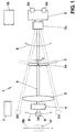
transverse bar 9 suspended movably in vertical direction and rotatably, preferably by ±90°. Thetransverse bar 9 carries theX-ray source 2, theX-ray collimator 3, thecassette holder 4 and the single- ormulti-line X-ray detector X-ray source 2, theX-ray collimator 3, thecassette holder 4 and the single- ormulti-line X-ray detector transverse bar 9 and are tiltable with respect to thetransverse bar 9. - In Fig. 1 the scanning is done by a
vertical swivelling movement 8 essentially about theX-ray source 2. Thetransverse bar 9 in the middle position (a) (straight lines) is oriented horizontally or vertically depending on whether thepatient 5 is standing/sitting or lying. Thebar 9 may also be oriented under arbitrary angles relative to thepatient 5. The dashed lines indicate the extreme positions (b), (c) of theswivelling movement 8. Owing to thebar 9 the detector 6 (with or without cassette holder 4) and theX-ray collimator 3 travel coordinately on a circle segment. This motion might also be achieved using separate mountings for thedetector 6 andcollimator 3. Alternatively thedetector 17 may travel along astraight line segment 8b in coordination with the swivelling movement of theX-ray collimator 3 andX-ray source 2. The movements shall be driven by at least onemotor 7. - Fig. 2 shows a
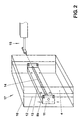
preferred detector arrangement 17 in greater detail. The single- ormulti-line X-ray detector 14 may be placed behind thecassette holder 4, which is shown only in a general simplified manner and is a conventional holder for X-ray films. Thedetector 14 may as well be placed in front of theX-ray film holder 4, if it can be moved out of the way during the film exposure. Thedetector 14 may be accomodated together with thecassette holder 4 in acommon housing 10 to form an integrated photographic/digital detector 17. As shown thedetector 14 is preferably mounted inside thehousing 10 on anelongated carriage 11 that is perpendicularly movable along astraight line segment 8b of guiding rails 12. Thecarriage 11 comprises arotatable plate 13 that carries thedetector 14 and is tilted towards theX-ray source 2 by amotor drive unit 15 in coordination with the up/down-movement 8b (patient standing/sitting) or backward/forward-movement 8b (patient lying) of thecarriage 11 inside thehousing 10 and/or of thehousing 10 itself. - Fig. 3 shows an alternative scanning movement where the
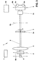
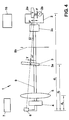
transverse bar 9 shifts theX-ray source 2,X-ray collimator 3,cassette holder 4 and digital detector 6 (or integrated photographic/digital detector 17) instraight direction 8b up/down (patient standing/sitting) or backward/forward (patient lying). This is most easily accomplished by moving the suspension arrangement of thetransverse bar 9 along a straight supporting part (not shown). - Fig. 4 shows a configuration for minimizing the X-ray dosage during the digital X-ray scan. In this embodiment the single- or multi-line X-ray detector 6 (or 14, not shown) is mounted in a position shifted towards an
anode side 2a of theX-ray source 2 by an angle α, where 0°<α<β with β=anode angle. Note that theanode 2a is shown in actual shape and orientation, but not to scale, whereas thecathode 2b is only indicated schematically. - The optimal choice of positioning angle α results from a trade off between emitted intensity and apparent focal spot size F'. The intensity emitted under anode angle β, i. e. tangentially to the anode surface, is considerably filtered and decreased, mainly owing to the surface roughness of the anode material. The intensity strongly increases for decreasing positioning angles α<β and typically reaches 90% of its maximal value at α approximately equal to β/2. On the other hand the apparent focal size equals F'=F*sin(β-α)/sin(β) with F=actual focal spot size. F' is minimal, or ideally zero, for α=β and increases with decreasing positioning angles α<β. Preferably the positioning angle shall be chosen around α=β/2 for receiving a high-intensity X-ray beam with focal spot size reduced by a
factor 2.Conventional X-ray tubes 2 have anode target angles β between 12° and 16°. Consequently a useful range of positioning angles is 4°<α<12°, preferred 6°<α<8°, and most preferably α=6° when β=12° is assumed. - According to another embodiment the X-ray dosage and scattering radiation during digital X-ray scanning can be further reduced by an adequate choice of the geometrical beam parameters, such as apparent focal spot size F', collimator slit width y and distances d1 between apparent focus and
detector 6, d2 betweenX-ray collimator 3 anddetector 6 and d3 betweenpatient 5 anddetector 6. The goals of an optimal parameter choice are: (i) fan beam width at detector site < pixel width (given by scintillator crystal width); (ii) reduce half-shadow zones to diminish radiation passing by thedetector 6; thereby the patient's X-ray exposure is further minimized; (iii) provide sufficient absolute intensity; and (iv) small patient-detector distance d3 to reduce scattering from the X-rayed object. Therefore a slit width y of the order of or smaller than the scintillator crystal width shall be chosen. The half-shadow zones result from the finite apparent focal spot size F' geometrically imaged through thecollimator slit 3a. The intensity side lobes extending laterally over more than one pixel size are kept low by decreasing F', y and the image distance d2. For providing enough absolute intensity the slit width y must be large enough. Finally the patient-detector distance d3 shall be short. For a pixel size (in particular width of scintillator crystal) of 0.4 mm preferred parameter ranges are: slit width 0.2 mm<y<1.5 mm; overall distance 900 mm<d1<1300 mm; image distance 500 mm<d2<700 mm; and patient-detector distance 10 mm<d3<200 mm. - In conclusion a novel integrated photographic and digital X-raying system is disclosed that is useful to create fast digital full body images with low dosage and partial body images with high photographic resolution.
Claims (10)
- X-ray system (1) comprising an X-ray source (2) and a cassette holder (4) for photographic films, a support for holding the X-ray source (2) and the cassette holder (4) in fixed positions for photographic X-ray imaging and a control unit (2c) for steering the X-ray system, characterized in that additional means (3, 3a, 6, 14, 16, 17) for digital X-ray scanning and imaging are provided.
- The X-ray system (1) according to claim 1, characterized in thata) the X-ray system (1) is switchable between photographic and digital X-ray imaging andb) in particular means for switching between photographic and digital X-ray imaging and means for steering the digital X-ray scanning are provided.
- The X-ray system (1) according to one of the claims 1-2, characterized in that the additional means (3, 3a, 6, 14, 16, 17) comprise an X-ray collimator (3), a pixeled X-ray detector (6, 14), means for coordinately moving the X-ray source (2), the collimator (3) and the pixeled X-ray detector (6, 14) for scanning an area (5) and means (16) for digital data acquisition from the pixeled X-ray detector (6, 14).
- The X-ray system (1) according to claim 3, characterized in thata) the X-ray collimator (3) has a slit (3a) with adjustable width y,b) the X-ray collimator (3) is removable or the slit (3a) is openable for photographic X-ray imaging andc) in particular the X-ray collimator (3) or the slit (3a) is steered by a sensor indicating the presence of a photographic film in the cassette holder (4) or by a switch in the cassette holder (4).
- The X-ray system (1) according to one of the claims 3-4, characterized in thata) the pixeled X-ray detector (6, 14) is a single- or multi-line X-ray detector (6, 14) with X-ray sensitive elements andb) in particular the X-ray sensitive elements comprise scintillator crystals and optical detectors, that are connected to at least one A/D converter and to a microcomputer (16) for serial readout.
- The X-ray system (1) according to one of the claims 3-5, characterized in thata) the single- or multi-line X-ray detector (14) is placed behind the cassette holder (4) and/orb) the single- or multi-line X-ray detector (14) and the cassette holder (4) are accomodated in a common housing (10) and/orc) the single- or multi-line X-ray detector (14) is mounted inside a housing (10) on an elongated carriage (11) that is perpendicularly movable and coordinately tiltable towards the X-ray source (2).
- The X-ray system (1) according to one of the claims 3-6, characterized in thata) the single- or multi-line X-ray detector (6, 14) is mounted in a position shifted towards an anode side (2a) of the X-ray source (2) by an angle α, where 0°<α<β with β=anode angle andb) in particular 4°<α<12°, preferably α=6° with β=12°.
- The X-ray system (1) according to one of the claims 3-7, characterized in that the single- or multi-line X-ray detector (6, 14) has means for gain and/or offset correction of analog signals from each pixel and/or from the whole detector (6, 14).
- The X-ray system (1) according to one of the claims 3-8, characterized in thata) the single- or multi-line X-ray detector (6, 14) has a digital signal processor for detector control and data acquisition and/orb) the single- or multi-line X-ray detector (6, 14) has a digital memory for data acquisition and data storage.
- The X-ray system (1) according to one of the claims 3-9, characterized in thata) the support comprises a transverse bar (9) suspended movably in vertical direction and rotatably, preferably by ±90°,b) the transverse bar (9) carries the X-ray source (2), the X-ray collimator (3), the cassette holder (4) and the single- or multi-line X-ray detector (6, 14) andc) in particular the X-ray source (2), the X-ray collimator (3), the cassette holder (4) and the single- or multi-line X-ray detector (6, 14) are movable along the transverse bar (9) and are tiltable with respect to the transverse bar (9).
Priority Applications (10)
| Application Number | Priority Date | Filing Date | Title |
|---|---|---|---|
| EP99112248A EP1062913A1 (en) | 1999-06-25 | 1999-06-25 | Digital scanning and photographic imaging X-ray system |
| EP00927665A EP1189537B1 (en) | 1999-06-25 | 2000-05-29 | Digital x-ray scanning apparatus |
| AT00927665T ATE275874T1 (en) | 1999-06-25 | 2000-05-29 | DIGITAL SCANNING X-RAY DEVICE |
| AU46050/00A AU4605000A (en) | 1999-06-25 | 2000-05-29 | Digital x-ray scanning apparatus |
| DE60013822T DE60013822T2 (en) | 1999-06-25 | 2000-05-29 | DIGITAL SCREENING UNIT |
| JP2001505811A JP4522630B2 (en) | 1999-06-25 | 2000-05-29 | Digital X-ray scanning device |
| US10/019,323 US6940948B1 (en) | 1999-06-25 | 2000-05-29 | Digital X-ray scanning apparatus |
| PCT/IB2000/000725 WO2001000092A1 (en) | 1999-06-25 | 2000-05-29 | Digital x-ray scanning apparatus |
| ES00927665T ES2228519T3 (en) | 1999-06-25 | 2000-05-29 | DIGITAL EXPLORATION DEVICE FOR X-RAYS. |
| HK02107194.7A HK1047397B (en) | 1999-06-25 | 2002-09-27 | Digital x-ray scanning apparatus |
Applications Claiming Priority (1)
| Application Number | Priority Date | Filing Date | Title |
|---|---|---|---|
| EP99112248A EP1062913A1 (en) | 1999-06-25 | 1999-06-25 | Digital scanning and photographic imaging X-ray system |
Publications (1)
| Publication Number | Publication Date |
|---|---|
| EP1062913A1 true EP1062913A1 (en) | 2000-12-27 |
Family
ID=8238427
Family Applications (2)
| Application Number | Title | Priority Date | Filing Date |
|---|---|---|---|
| EP99112248A Withdrawn EP1062913A1 (en) | 1999-06-25 | 1999-06-25 | Digital scanning and photographic imaging X-ray system |
| EP00927665A Expired - Lifetime EP1189537B1 (en) | 1999-06-25 | 2000-05-29 | Digital x-ray scanning apparatus |
Family Applications After (1)
| Application Number | Title | Priority Date | Filing Date |
|---|---|---|---|
| EP00927665A Expired - Lifetime EP1189537B1 (en) | 1999-06-25 | 2000-05-29 | Digital x-ray scanning apparatus |
Country Status (9)
| Country | Link |
|---|---|
| US (1) | US6940948B1 (en) |
| EP (2) | EP1062913A1 (en) |
| JP (1) | JP4522630B2 (en) |
| AT (1) | ATE275874T1 (en) |
| AU (1) | AU4605000A (en) |
| DE (1) | DE60013822T2 (en) |
| ES (1) | ES2228519T3 (en) |
| HK (1) | HK1047397B (en) |
| WO (1) | WO2001000092A1 (en) |
Cited By (4)
| Publication number | Priority date | Publication date | Assignee | Title |
|---|---|---|---|---|
| WO2002069349A1 (en) | 2001-02-27 | 2002-09-06 | Elekta Ab (Publ) | Radiotherapeutic apparatus |
| GB2376162A (en) * | 2001-03-13 | 2002-12-04 | Peter Coxon | Low cost digital X-ray imaging system utilising a document scanning apparatus |
| WO2004049946A1 (en) * | 2002-12-04 | 2004-06-17 | Planmed Oy | Digital imaging method and apparatus for mammography |
| CN102793559A (en) * | 2011-05-24 | 2012-11-28 | 上海世鹏实验室科技发展有限公司 | Safety detection and scanning device for human body |
Families Citing this family (28)
| Publication number | Priority date | Publication date | Assignee | Title |
|---|---|---|---|---|
| US6647092B2 (en) * | 2002-01-18 | 2003-11-11 | General Electric Company | Radiation imaging system and method of collimation |
| EP2345370A3 (en) * | 2002-03-19 | 2012-05-09 | Breakaway Imaging, Llc | Computer tomography with a detector following the movement of a pivotable x-ray source |
| US7099431B2 (en) * | 2003-06-09 | 2006-08-29 | Canon Kabushiki Kaisha | Radiation imaging apparatus |
| DE102005002559B4 (en) * | 2005-01-19 | 2007-06-21 | Siemens Ag | X-ray device with error protection circuit |
| JP4957096B2 (en) * | 2006-06-30 | 2012-06-20 | 株式会社島津製作所 | X-ray diagnostic equipment |
| KR101577475B1 (en) * | 2008-02-20 | 2015-12-14 | 이미징 사이언시즈 인터내셔널 엘엘씨 | Adjustable scanner |
| US7686511B2 (en) * | 2008-03-06 | 2010-03-30 | Moshe Ein-Gal | Angular irradiation in an upright treatment system |
| JP5455446B2 (en) * | 2009-06-02 | 2014-03-26 | キヤノン株式会社 | Radiation imaging apparatus, control method and program for radiation imaging apparatus |
| JP5438493B2 (en) * | 2009-12-22 | 2014-03-12 | 富士フイルム株式会社 | Radiation imaging system and auxiliary device thereof |
| JP5661920B2 (en) * | 2010-05-06 | 2015-01-28 | イーオーエス イメージング | Imaging apparatus and imaging method |
| JP5579636B2 (en) * | 2011-02-07 | 2014-08-27 | 富士フイルム株式会社 | Radiographic imaging apparatus and radiographic imaging method |
| KR101209518B1 (en) * | 2012-02-23 | 2012-12-07 | 테크밸리 주식회사 | Helical ct apparatus |
| FR2993447B1 (en) * | 2012-07-17 | 2014-07-11 | Gen Electric | METHOD AND SYSTEM FOR PROCESSING IMAGES FOR 3D DISPLAY OF AN ORGAN OF A PATIENT |
| US9861329B2 (en) * | 2012-10-11 | 2018-01-09 | Samsung Electronics Co., Ltd. | X-ray apparatus and method of capturing X-ray image |
| USRE48415E1 (en) * | 2012-11-08 | 2021-02-02 | J. Morita Manufacturing Corporation | X-ray photography apparatus |
| CN103901494B (en) * | 2012-12-27 | 2017-08-29 | 同方威视技术股份有限公司 | Human body back scattering safe examination system and its method |
| EP3099238B1 (en) * | 2014-01-27 | 2019-09-11 | Epica International, Inc. | Radiological imaging device with advanced sensors |
| US9510793B2 (en) | 2014-01-27 | 2016-12-06 | Epica International, Inc. | Radiological imaging device with advanced sensors |
| KR102126508B1 (en) * | 2014-02-14 | 2020-06-24 | 삼성전자주식회사 | X-ray photographing apparatus and method for using the same and x-ray image obtaining method |
| DE102016205176A1 (en) * | 2016-03-30 | 2017-10-05 | Siemens Healthcare Gmbh | Apparatus and method for creating an X-ray panoramic image |
| US10520636B2 (en) | 2017-10-13 | 2019-12-31 | John R. Allen | Whole-body transmission x-ray scanner and methods for whole-body scanning |
| US11628312B2 (en) | 2017-11-06 | 2023-04-18 | The Research Foundation For The State University Of New York | System and method for dual-use computed tomography for imaging and radiation therapy |
| AU2019206645A1 (en) | 2018-01-11 | 2020-08-06 | Tek84 Inc | Compact body scanner |
| US11808912B2 (en) | 2018-01-11 | 2023-11-07 | Tek84 Inc. | Compact body scanner |
| DE102018103907A1 (en) * | 2018-02-21 | 2019-08-22 | Alexander Ulanov | X-ray examination device |
| RU186354U1 (en) * | 2018-06-07 | 2019-01-16 | федеральное государственное бюджетное образовательное учреждение высшего образования "Нижегородский государственный технический университет им. Р.Е. Алексеева" (НГТУ) | X-ray installation |
| US10881371B2 (en) | 2018-12-27 | 2021-01-05 | Medtronic Navigation, Inc. | System and method for imaging a subject |
| US11071507B2 (en) * | 2018-12-27 | 2021-07-27 | Medtronic Navigation, Inc. | System and method for imaging a subject |
Citations (6)
| Publication number | Priority date | Publication date | Assignee | Title |
|---|---|---|---|---|
| US4628356A (en) | 1984-10-15 | 1986-12-09 | Imagex, Inc. | Digital X-ray scanner |
| EP0209930A1 (en) * | 1985-06-21 | 1987-01-28 | B.V. Optische Industrie "De Oude Delft" | Apparatus and method for slit radiography with different x-ray energies |
| US4773087A (en) * | 1986-04-14 | 1988-09-20 | University Of Rochester | Quality of shadowgraphic x-ray images |
| EP0291299A1 (en) | 1987-05-11 | 1988-11-17 | General Electric Company | Digital radiographic imaging system and method therefor |
| WO1998035613A1 (en) * | 1997-02-14 | 1998-08-20 | Koninklijke Philips Electronics N.V. | X-ray scanner with means for conventional radiography |
| EP0904734A2 (en) * | 1997-09-30 | 1999-03-31 | Kabushikikaisha Morita Seisakusho | Panoramic radiographic apparatus and digital sensor cassette used for same apparatus |
Family Cites Families (17)
| Publication number | Priority date | Publication date | Assignee | Title |
|---|---|---|---|---|
| US3869615A (en) * | 1973-06-28 | 1975-03-04 | Nasa | Multiplate focusing collimator |
| US4024403A (en) * | 1976-03-19 | 1977-05-17 | General Electric Company | X-ray cardiovascular examination apparatus |
| US4179100A (en) * | 1977-08-01 | 1979-12-18 | University Of Pittsburgh | Radiography apparatus |
| US4363128A (en) * | 1980-09-29 | 1982-12-07 | John K. Grady | X-Ray drive apparatus |
| US4358856A (en) * | 1980-10-31 | 1982-11-09 | General Electric Company | Multiaxial x-ray apparatus |
| DE3663618D1 (en) * | 1985-10-09 | 1989-07-06 | Siemens Ag | Diagnostic x-ray installation comprising components to be positioned by means of a control device |
| IT1217701B (en) * | 1988-05-24 | 1990-03-30 | Gen Medical Merate Spa | NUMERICAL CALIBRATION PROCEDURE FOR INSTALLATION OF RADIOLOGY AND INSTALLATION OF NUMERICAL CALIBRATION FOR THE IMPLEMENTATION OF THE PROCEDURE |
| NL9100019A (en) * | 1991-01-09 | 1992-08-03 | Philips Nv | ROENTGEN RESEARCH DEVICE. |
| US5287546A (en) * | 1992-09-14 | 1994-02-15 | Lunar Corporation | Patient positioning apparatus for bone scanning |
| US5220589A (en) * | 1991-07-18 | 1993-06-15 | General Electric Company | Correction circuit for a floating-point amplifier |
| US5463668A (en) * | 1993-09-14 | 1995-10-31 | Kabushiki Kaisha Toshiba | X-ray diagnosis apparatus |
| US5617465A (en) * | 1995-12-08 | 1997-04-01 | Xedar Corporation | Scan-type X-ray imaging with fixed converter |
| US5994713A (en) * | 1997-06-25 | 1999-11-30 | Quantum Imaging Corp. | Filmless photon imaging apparatus |
| DE19728108A1 (en) * | 1997-07-02 | 1999-01-07 | Philips Patentverwaltung | X-ray examination device with a swiveling patient table |
| US6152598A (en) * | 1997-09-02 | 2000-11-28 | Kabushiki Kaisha Toshiba | R/F and chest radiography compatible X-ray imaging table |
| JP2000116631A (en) * | 1998-10-16 | 2000-04-25 | Toshiba Corp | X-ray diagnostic instrument |
| US6200024B1 (en) * | 1998-11-27 | 2001-03-13 | Picker International, Inc. | Virtual C-arm robotic positioning system for use in radiographic imaging equipment |
-
1999
- 1999-06-25 EP EP99112248A patent/EP1062913A1/en not_active Withdrawn
-
2000
- 2000-05-29 JP JP2001505811A patent/JP4522630B2/en not_active Expired - Fee Related
- 2000-05-29 ES ES00927665T patent/ES2228519T3/en not_active Expired - Lifetime
- 2000-05-29 US US10/019,323 patent/US6940948B1/en not_active Expired - Fee Related
- 2000-05-29 AT AT00927665T patent/ATE275874T1/en active
- 2000-05-29 WO PCT/IB2000/000725 patent/WO2001000092A1/en active IP Right Grant
- 2000-05-29 EP EP00927665A patent/EP1189537B1/en not_active Expired - Lifetime
- 2000-05-29 DE DE60013822T patent/DE60013822T2/en not_active Expired - Lifetime
- 2000-05-29 AU AU46050/00A patent/AU4605000A/en not_active Abandoned
-
2002
- 2002-09-27 HK HK02107194.7A patent/HK1047397B/en not_active IP Right Cessation
Patent Citations (6)
| Publication number | Priority date | Publication date | Assignee | Title |
|---|---|---|---|---|
| US4628356A (en) | 1984-10-15 | 1986-12-09 | Imagex, Inc. | Digital X-ray scanner |
| EP0209930A1 (en) * | 1985-06-21 | 1987-01-28 | B.V. Optische Industrie "De Oude Delft" | Apparatus and method for slit radiography with different x-ray energies |
| US4773087A (en) * | 1986-04-14 | 1988-09-20 | University Of Rochester | Quality of shadowgraphic x-ray images |
| EP0291299A1 (en) | 1987-05-11 | 1988-11-17 | General Electric Company | Digital radiographic imaging system and method therefor |
| WO1998035613A1 (en) * | 1997-02-14 | 1998-08-20 | Koninklijke Philips Electronics N.V. | X-ray scanner with means for conventional radiography |
| EP0904734A2 (en) * | 1997-09-30 | 1999-03-31 | Kabushikikaisha Morita Seisakusho | Panoramic radiographic apparatus and digital sensor cassette used for same apparatus |
Cited By (6)
| Publication number | Priority date | Publication date | Assignee | Title |
|---|---|---|---|---|
| WO2002069349A1 (en) | 2001-02-27 | 2002-09-06 | Elekta Ab (Publ) | Radiotherapeutic apparatus |
| EP1364375B1 (en) * | 2001-02-27 | 2014-04-09 | Elekta AB (publ) | Radiotherapeutic apparatus |
| GB2376162A (en) * | 2001-03-13 | 2002-12-04 | Peter Coxon | Low cost digital X-ray imaging system utilising a document scanning apparatus |
| WO2004049946A1 (en) * | 2002-12-04 | 2004-06-17 | Planmed Oy | Digital imaging method and apparatus for mammography |
| US7590217B2 (en) | 2002-12-04 | 2009-09-15 | Planmed Oy | Digital imaging method and apparatus for mammography |
| CN102793559A (en) * | 2011-05-24 | 2012-11-28 | 上海世鹏实验室科技发展有限公司 | Safety detection and scanning device for human body |
Also Published As
| Publication number | Publication date |
|---|---|
| JP2003503095A (en) | 2003-01-28 |
| EP1189537B1 (en) | 2004-09-15 |
| ES2228519T3 (en) | 2005-04-16 |
| EP1189537A1 (en) | 2002-03-27 |
| WO2001000092A1 (en) | 2001-01-04 |
| JP4522630B2 (en) | 2010-08-11 |
| ATE275874T1 (en) | 2004-10-15 |
| US6940948B1 (en) | 2005-09-06 |
| HK1047397A1 (en) | 2003-02-21 |
| DE60013822D1 (en) | 2004-10-21 |
| AU4605000A (en) | 2001-01-31 |
| HK1047397B (en) | 2005-06-30 |
| DE60013822T2 (en) | 2005-11-17 |
Similar Documents
| Publication | Publication Date | Title |
|---|---|---|
| EP1062913A1 (en) | Digital scanning and photographic imaging X-ray system | |
| US10251614B2 (en) | Tiled digital radiography detectors for long-length imaging | |
| EP1848985B1 (en) | Multiple mode flat panel x-ray imaging system | |
| EP0948930B1 (en) | Acquiring volumetric image data | |
| US6990170B2 (en) | X-ray computed tomographic imaging apparatus | |
| EP1016375B1 (en) | Imaging system for generating high quality images | |
| US8094777B2 (en) | Digital mammography scanning system | |
| US5142557A (en) | CCD and phosphor screen digital radiology apparatus and method for high resolution mammography | |
| US7289596B2 (en) | Radiation tomography apparatus and scan condition setting device | |
| US7831291B2 (en) | Subject moving apparatus and imaging apparatus | |
| JP2004097842A (en) | Roentgen ray diagnostic system | |
| US10499863B2 (en) | Tiled digital radiography detectors for long-length imaging | |
| JP2003180670A5 (en) | ||
| US6987827B2 (en) | Apparatus and method for X-ray computer tomography | |
| JPH0819534A (en) | X-ray photographing device serving also for panorama cephalo photographing and cephalo x-ray photographing device | |
| JP2003052677A (en) | Radiological imaging unit | |
| JP2002516136A (en) | X-ray image forming device | |
| JPH0921876A (en) | Improved type gamma-camera image pickup system | |
| JP2006116174A (en) | Photographing apparatus | |
| JP2003010164A (en) | X-ray equipment | |
| JP5448316B2 (en) | Radiography equipment | |
| JPH06233754A (en) | X-ray television | |
| JP2006020707A (en) | Imaging apparatus and subject carrier device |
Legal Events
| Date | Code | Title | Description |
|---|---|---|---|
| PUAI | Public reference made under article 153(3) epc to a published international application that has entered the european phase |
Free format text: ORIGINAL CODE: 0009012 |
|
| AK | Designated contracting states |
Kind code of ref document: A1 Designated state(s): AT BE CH CY DE DK ES FI FR GB GR IE IT LI LU MC NL PT SE |
|
| AX | Request for extension of the european patent |
Free format text: AL;LT;LV;MK;RO;SI |
|
| 17P | Request for examination filed |
Effective date: 20010611 |
|
| AKX | Designation fees paid |
Free format text: AT BE CH CY DE DK ES FI FR GB GR IE IT LI LU MC NL PT SE |
|
| AXX | Extension fees paid |
Free format text: AL PAYMENT 20010611;LT PAYMENT 20010611;LV PAYMENT 20010611;MK PAYMENT 20010611;RO PAYMENT 20010611;SI PAYMENT 20010611 |
|
| RAP1 | Party data changed (applicant data changed or rights of an application transferred) |
Owner name: DDI DIRECT DIGITAL IMAGING GMBH |
|
| 17Q | First examination report despatched |
Effective date: 20030707 |
|
| STAA | Information on the status of an ep patent application or granted ep patent |
Free format text: STATUS: THE APPLICATION IS DEEMED TO BE WITHDRAWN |
|
| 18D | Application deemed to be withdrawn |
Effective date: 20040120 |