EP0974860A1 - Screw for securising optical lens to clasp - Google Patents
Screw for securising optical lens to clasp Download PDFInfo
- Publication number
- EP0974860A1 EP0974860A1 EP99305757A EP99305757A EP0974860A1 EP 0974860 A1 EP0974860 A1 EP 0974860A1 EP 99305757 A EP99305757 A EP 99305757A EP 99305757 A EP99305757 A EP 99305757A EP 0974860 A1 EP0974860 A1 EP 0974860A1
- Authority
- EP
- European Patent Office
- Prior art keywords
- screw
- clasp
- lens
- edge
- clasps
- Prior art date
- Legal status (The legal status is an assumption and is not a legal conclusion. Google has not performed a legal analysis and makes no representation as to the accuracy of the status listed.)
- Granted
Links
Images


Classifications
-
- G—PHYSICS
- G02—OPTICS
- G02C—SPECTACLES; SUNGLASSES OR GOGGLES INSOFAR AS THEY HAVE THE SAME FEATURES AS SPECTACLES; CONTACT LENSES
- G02C5/00—Constructions of non-optical parts
-
- G—PHYSICS
- G02—OPTICS
- G02C—SPECTACLES; SUNGLASSES OR GOGGLES INSOFAR AS THEY HAVE THE SAME FEATURES AS SPECTACLES; CONTACT LENSES
- G02C9/00—Attaching auxiliary optical parts
- G02C9/04—Attaching auxiliary optical parts by fitting over or clamping on
Definitions
- the present invention relates to a clip-on sunglasses assembly and more particularly to a screw for securing the sunglass lenses to clasps which permit the assembly to be removably mounted on eyeglasses and to a method for utilizing same to customize such assemblies to fit different size and shape eyeglasses configurations.
- the present invention is primarily intended and hence described herein for use in securing sunglass lenses employed in clip-on sunglasses assemblies, the type of lenses to be secured should not be considered to be a limitation on the invention.
- the present invention will serve equally well to secure any type of optical lens.
- prescription lenses could be secured to a clip-on assembly designed to be mounted over eyeglasses to modify the present prescription, such as to form bifocal lenses for reading.
- Clip-on sunglasses assemblies include a metal or plastic frame member which carries a pair of light attenuating plastic or glass lenses.
- a mechanism is provided for removably mounting the clip-on assembly on eyeglasses.
- Conventional mounting mechanisms either attach to the bridge of the eyeglasses (known as “center bridge mount”) or to the periphery of the eyeglass frame.
- the clip-on assembly In order to be commercially acceptable, the clip-on assembly must be light in weight, rugged and inexpensive. It must be easy to mount and to remove from the eyeglasses. It must also mount without damaging the eyeglasses, particularly the lenses.
- One common type of center bridge mounting mechanism utilizes a clamp mounted on the bridge of the clip-on assembly.
- the clamp includes pairs of opposing clamp parts which are spring loaded toward each other so as to frictionally engage the lenses of the eyeglasses therebetween. Examples of this type of clamp are disclosed in U.S. Patent No. 3,575,497 issued April 20, 1971 to Leblanc, U.S. Patent No. 5,164,749 issued November 17, 1992 to Shelton and U.S. Design Patent No. Des 350,359 issued September 6, 1994 to Friedman.
- the clamp mechanism consists of several parts which must be fabricated and assembled, making them relatively expensive and not very reliable. The parts clamp tightly to the lenses, potentially scratching the lenses. Moreover, they may obstruct the view partially.
- the peripheral type mounting mechanisms do not have the drawbacks of the center bridge clamp. However, because they must be positioned to fit the eyeglasses frame precisely, the assembly which utilizes this type of mounting must be customized for each frame. Such mechanisms employ a number of clasps which permit the assembly to "snap-fit" over an eyeglasses frame.
- This type of clip-on mount is illustrated in U.S. Patent No. 5,123,724 issued June 23 1992 to Salk.
- the clasps are affixed to and carry the sunglass lenses.
- the clasps must retain the lenses in a manner which is secure enough to carry the weight of the lens and to prevent relative movement of the lens. This must be accomplished without unduly stressing the lens surface, which can lead to cracking of the lens.
- Salk for example, teaches the use of adhesive to secure the lens to the clasp.
- adhesive is messy, difficult for opticians to use and may not retain the lenses securely.
- the assembly In order to appropriately fit the frame of the eyeglasses, the assembly must be customizable so as to fit the particular one of the large number of different size and shape frames upon which the assembly will be used. It is therefore necessary to fabricate the clasps such that they can be easily affixed to the lenses by the optician at any location which is required.
- a screw for securing an optical lens to a clasp includes a body with an end adapted to abut the lens surface.
- the screw end includes means for forming a groove in the lens surface as the screw is rotated.
- the groove forming means comprises a recess which defines an edge in the screw end.
- the edge is spaced from the center of the screw and is preferably substantially circular.
- the edge is preferably relatively sharp.
- the screw body has an axis about which it is rotated to tighten the screw.
- the recess is located on the axis.
- a clasp for retaining an optical lens includes a wall with an internally threaded screw receiving opening.
- a screw with an externally threaded body is adapted to be received within the opening.
- the screw body has an end adapted to abut the lens surface when the screw is rotatably received in the opening.
- the end of the screw includes means for forming a groove in the lens surface as the screw is rotated within the opening.
- the groove forming means comprises a recess which defines an edge in the screw end.
- the edge is spaced from the center of the screw and is preferably substantially circular.
- the edge is preferably relatively sharp.
- the screw body has an axis.
- the recess is located on the screw body axis.
- the edge forms a substantially circular groove in the lens surface.
- the externally threaded screw wall cooperates with the internally threaded clasp opening as the screw is rotated to cause the screw to form the groove.
- a second wall is provided as part of the clasp.
- the second wall is spaced from the first wall a distance greater than the thickness of the optical lens.
- the clasp further includes a tail bar.
- the tail bar extends from the first wall.
- a bridge member is affixed to the clasp.
- the bridge member has an end.
- the clasp is affixed to the end of the bridge member.
- a method of forming a custom clip-on assembly for eyeglasses utilizes first and second clasps affixed to opposite ends of a bridge element, each clasp including a screw having an end with a recess defining an edge and a tail bar.
- the method comprises the steps of:
- the groove forming means of the lens engaging screw may include a blade with an edge for scoring the surface of a lens.
- the blade may have an annular profile, their being a bore extending along the longitudinal axis of the screw.
- the bore may be a blind bore, extending from the lens-abutting end of the screw.
- At least one side of the blade may taper away from the edge to give a frustoconical profile.
- the at least one side of the blade may taper such that the angle between the longitudinal axis of the screw and the frustoconical periphery may be at least 45°, perhaps 60° in the case of the outer side of the blade.
- a clasp for attaching clip-on sunglasses to prescription glasses comprising a clamping member having opposed limbs and a screw threadably engaged in one limb for driveably rotating towards the other limb, the screw being in accordance with a first aspect of the invention, whereby a lens disposed between the limbs is retainable therein upon driveable rotation of the screw towards the opposing limb into engagement with the lens.
- a clip-on sunglass assembly for a pair of prescription glasses (“spectacles”), the assembly comprising a pair of lenses, a bridge member, at least one clasp mounted on the bridge member for removably securing the assembly to the spectacles, wherein at least one clasp is according to an earlier aspect of the invention.
- a clip-on assembly is fabricated to be removably mounted on a pair of eyeglasses, generally designated B, through the use of clasps, generally designated C, four of which are shown.
- the assembly A is customized to accommodate the size and shape of the eyeglasses B.
- Assembly A includes a pair of optical elements or lenses 10, usually light attenuating in nature.
- Lenses 10 may be made of glass or plastic.
- a bridge member 12 is welded or otherwise affixed at each end to one of two upper clasps 14, 16.
- Lower clasps 18, 20 are positioned on the lower portions of the lenses 10.
- the bridge member is formed of thin metal so it can "flex" to permit mounting and removal of the clip-on assembly from the eyeglasses.
- Eyeglasses B consist of optical lenses 22, 24 and a metal or plastic frame 26 with hinged temple parts 28. Frame 26 retains lenses 22, 24.
- each clasp C is made of metal and includes a front wall 30, a rear wall 32 and a connecting part 34.
- Part 34 spaces walls 30, 32 apart and maintains the walls in a generally parallel relationship so as to form a lens receiving recess 36 therebetween.
- Wall 32 has an internally threaded bore 38 which extends through it and which is adapted to receive a screw 40.
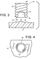
- the structure of screw 40 is best seen in Fig. 3.
- Fig. 3 shows that screw 40 has an externally threaded cylindrical body 42 with a head 44 on one end.
- the other end 46 of the screw is adapted to abut the surface of lens 10.
- Head 44 normally has a groove (not shown) adapted to accept the blade of a jeweler's screw driver, as is conventional. However, other head configurations are possible.
- End 46 is provided with a central recess 48, preferably centered on the central axis of the screw.
- Recess 48 defines an edge 50 spaced from the screw axis.
- Edge 50 is preferably circular and is relatively sharp.
- edge 50 displaces a small amount of the lens material and an arcuate groove 52 is formed in the lens surface.
- groove 52 will be substantially circular after the screw has been rotated at least once about its axis.
- Groove 52 is defined between an outer ring-like accumulation of material 54 and a central mound of material or protrusion 56. This distributes the stress applied to the lens surface by the screw over a substantial area, instead of being conventional screws. Thus, the screw can be tightened to adequately secure the lens relative to the clasp, without causing the lens to crack.
- tail bar 58 Extending from wall 32 is a tail bar 58 which has a heat shrinkable plastic sleeve 60 surrounding it. As best seen in Fig. 5, bar 58 is bent to form a recess to engage the frame of the eyeglasses. A protective layer 62 is provided on the surface of wall 32 where it is contacted by corner 64 of frame 26 to provide cushioning and prevent damage to the frame.
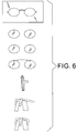
- Fig. 6 illustrates the steps in the custom fabrication process.
- the factory supplies a bridge element with first and second clasps affixed to the opposite ends.
- the optician or other optical worker traces the outline of eyeglasses B on to a flat sheet.
- the optical lenses 10 to be used in the clip-on assembly are edged, such that their size and shape matches that of the eyeglasses.
- the lenses 10 are marked to indicate where the clasps C will be positioned.
- the bridge element 12, with upper clasps 14, 16 welded to each end, is aligned with the markings for the upper clasps.
- Clasps 18 and 20 are positioned over the markings for the lower clasps. All clasps are secured by tightening screws 40.
- the clip-on assembly is aligned with the eyeglasses and tail bars 58 are bent so as to engage the frame 26 of the eyeglasses.
- the present invention relates to a clasp for securing optical lenses in a clip-on assembly which utilizes a uniquely structured screw to secure the lens without cracking the lens. This is accomplished by creating a recess in the screw which defines a circular edge. As the screw is rotated, lens material is displaced forming a circular groove in the lens surface which distributes the stress applied to the lens over a relatively large area, instead of concentrating it at a single point, which would tend to promote the formation of a crack in the lens.
Abstract
Description
- The present invention relates to a clip-on sunglasses assembly and more particularly to a screw for securing the sunglass lenses to clasps which permit the assembly to be removably mounted on eyeglasses and to a method for utilizing same to customize such assemblies to fit different size and shape eyeglasses configurations.
- Although the present invention is primarily intended and hence described herein for use in securing sunglass lenses employed in clip-on sunglasses assemblies, the type of lenses to be secured should not be considered to be a limitation on the invention. The present invention will serve equally well to secure any type of optical lens. For example, prescription lenses could be secured to a clip-on assembly designed to be mounted over eyeglasses to modify the present prescription, such as to form bifocal lenses for reading.
- Clip-on sunglasses assemblies include a metal or plastic frame member which carries a pair of light attenuating plastic or glass lenses. A mechanism is provided for removably mounting the clip-on assembly on eyeglasses. Conventional mounting mechanisms either attach to the bridge of the eyeglasses (known as "center bridge mount") or to the periphery of the eyeglass frame.
- In order to be commercially acceptable, the clip-on assembly must be light in weight, rugged and inexpensive. It must be easy to mount and to remove from the eyeglasses. It must also mount without damaging the eyeglasses, particularly the lenses.
- One common type of center bridge mounting mechanism utilizes a clamp mounted on the bridge of the clip-on assembly. The clamp includes pairs of opposing clamp parts which are spring loaded toward each other so as to frictionally engage the lenses of the eyeglasses therebetween. Examples of this type of clamp are disclosed in U.S. Patent No. 3,575,497 issued April 20, 1971 to Leblanc, U.S. Patent No. 5,164,749 issued November 17, 1992 to Shelton and U.S. Design Patent No. Des 350,359 issued September 6, 1994 to Friedman.
- These prior art clamp mechanisms have the advantage of being able to fit a variety of different eyeglasses styles. However, they have their drawbacks. The clamp mechanism consists of several parts which must be fabricated and assembled, making them relatively expensive and not very reliable. The parts clamp tightly to the lenses, potentially scratching the lenses. Moreover, they may obstruct the view partially.
- The peripheral type mounting mechanisms do not have the drawbacks of the center bridge clamp. However, because they must be positioned to fit the eyeglasses frame precisely, the assembly which utilizes this type of mounting must be customized for each frame. Such mechanisms employ a number of clasps which permit the assembly to "snap-fit" over an eyeglasses frame. One example of this type of clip-on mount is illustrated in U.S. Patent No. 5,123,724 issued June 23 1992 to Salk. The clasps are affixed to and carry the sunglass lenses. The clasps must retain the lenses in a manner which is secure enough to carry the weight of the lens and to prevent relative movement of the lens. This must be accomplished without unduly stressing the lens surface, which can lead to cracking of the lens.
- Salk, for example, teaches the use of adhesive to secure the lens to the clasp. However, adhesive is messy, difficult for opticians to use and may not retain the lenses securely.
- Others have used screws to clamp the lenses within recesses in the clasps. However, conventional screws will not retain the lenses securely unless they are extremely tight. Tightening the screw sufficiently to properly secure the lens may cause the lens to crack because the screw end tends to apply a high stress force on the lens in a very small area.
- Because the clasps are situated on the periphery of the lenses of the assembly, in order to appropriately fit the frame of the eyeglasses, the assembly must be customizable so as to fit the particular one of the large number of different size and shape frames upon which the assembly will be used. It is therefore necessary to fabricate the clasps such that they can be easily affixed to the lenses by the optician at any location which is required.
- In order to overcome the problems associated with cracking the lenses and at the same time provide clasps which permit customization, I have invented a unique screw for use in the clasps forming a clip-on sunglasses assembly which securely retain the lens without cracking them. The screw is simple in structure, inexpensive and reliable. It enables an optician to customize the clip-on assembly to fit a wide variety of different size and shape eyeglasses in an easy and quick fashion.
- There is a desire to provide a clasp for securing an optical lens which utilizes a uniquely structured screw which adequately secures the lens without causing it to crack. There is also a desire to provide a clasp for securing an optical lens which utilizes a screw designed to distribute the stress applied to the lens surface over a relatively large area.
- There is yet another desire to provide a clasp for securing an optical lens which permits a clip-on assembly to be customized to fit a large variety of different size and shaped eyeglasses in a simple and efficient manner.
- In accordance with one aspect of the present invention, a screw for securing an optical lens to a clasp is provided. The screw includes a body with an end adapted to abut the lens surface. The screw end includes means for forming a groove in the lens surface as the screw is rotated.
- The groove forming means comprises a recess which defines an edge in the screw end. The edge is spaced from the center of the screw and is preferably substantially circular. The edge is preferably relatively sharp.
- The screw body has an axis about which it is rotated to tighten the screw. Preferably, the recess is located on the axis.
- In accordance with another aspect of the present invention, a clasp for retaining an optical lens is provided. The clasp includes a wall with an internally threaded screw receiving opening. A screw with an externally threaded body is adapted to be received within the opening. The screw body has an end adapted to abut the lens surface when the screw is rotatably received in the opening. The end of the screw includes means for forming a groove in the lens surface as the screw is rotated within the opening.
- The groove forming means comprises a recess which defines an edge in the screw end. The edge is spaced from the center of the screw and is preferably substantially circular. The edge is preferably relatively sharp.
- The screw body has an axis. The recess is located on the screw body axis.
- The edge forms a substantially circular groove in the lens surface. The externally threaded screw wall cooperates with the internally threaded clasp opening as the screw is rotated to cause the screw to form the groove.
- A second wall is provided as part of the clasp. The second wall is spaced from the first wall a distance greater than the thickness of the optical lens.
- The clasp further includes a tail bar. The tail bar extends from the first wall.
- A bridge member is affixed to the clasp. The bridge member has an end. The clasp is affixed to the end of the bridge member.
- In accordance with another aspect of the present invention, a method of forming a custom clip-on assembly for eyeglasses is provided. The method utilizes first and second clasps affixed to opposite ends of a bridge element, each clasp including a screw having an end with a recess defining an edge and a tail bar. The method comprises the steps of:
- (a) forming first and second optical lenses to conform to the shape of eyeglasses,
- (b) marking places on each of the first and second optical lenses where the first and second clasps are to be located,
- (c) aligning the first and second clasps respectively with the markings,
- (d) inserting the optical lenses into the clasps;
- (e) rotating the screws such that the end of each screw forms a substantially circular groove in the surface of each optical lens,
- (f) aligning the clip-on assembly with the eyeglasses, and
- (g) bending the tail bars of the clasps to engage the frame of the eyeglasses. The method also comprises the step of affixing third and fourth clasps to the optical lenses.
-
- In accordance with the first aspect of the invention, the groove forming means of the lens engaging screw may include a blade with an edge for scoring the surface of a lens. The blade may have an annular profile, their being a bore extending along the longitudinal axis of the screw. The bore may be a blind bore, extending from the lens-abutting end of the screw. At least one side of the blade may taper away from the edge to give a frustoconical profile. The at least one side of the blade may taper such that the angle between the longitudinal axis of the screw and the frustoconical periphery may be at least 45°, perhaps 60° in the case of the outer side of the blade.
- According to a further aspect of the invention, there is provided a clasp for attaching clip-on sunglasses to prescription glasses, comprising a clamping member having opposed limbs and a screw threadably engaged in one limb for driveably rotating towards the other limb, the screw being in accordance with a first aspect of the invention, whereby a lens disposed between the limbs is retainable therein upon driveable rotation of the screw towards the opposing limb into engagement with the lens.
- According to yet another aspect of the invention, there is provided a clip-on sunglass assembly for a pair of prescription glasses ("spectacles"), the assembly comprising a pair of lenses, a bridge member, at least one clasp mounted on the bridge member for removably securing the assembly to the spectacles, wherein at least one clasp is according to an earlier aspect of the invention.
- Embodiments of the invention will now be described by way of example, with reference to the accompanying drawings, in which like numbers refer to like parts and in which:
- Fig. 1 is an exploded isometric view of a typical clip-on assembly with the clasps embodying one aspect of the present invention and eyeglasses which the assembly has been customized to fit;
- Fig. 2 is a greatly enlarged cross-sectional view of one of the clasps embodying one aspect of the present invention, prior to bending the tail bar;
- Fig. 3 is a greatly enlarged cross-sectional view of a screw utilized in the clasp of figure 2 and a greatly enlarged (idealized) cross-sectional view of the lens surface, with a groove formed by the screw;
- Fig. 4 is a greatly enlarged (idealized) elevational view of the lens surface of figure 3 with the groove;
- Fig. 5 is a greatly enlarged cross-sectional view of the clasp of figure 3 with its tail bar bent to engage the eyeglass frame; and
- Fig. 6 is a flow chart showing the steps for fabricating a custom clip-on assembly with the clasps embodying the present invention.
-
- As seen in Fig. 1, a clip-on assembly, generally designed A, is fabricated to be removably mounted on a pair of eyeglasses, generally designated B, through the use of clasps, generally designated C, four of which are shown. As described in detail below, the assembly A is customized to accommodate the size and shape of the eyeglasses B.
- Assembly A includes a pair of optical elements or
lenses 10, usually light attenuating in nature.Lenses 10 may be made of glass or plastic. Abridge member 12 is welded or otherwise affixed at each end to one of twoupper clasps lenses 10. The bridge member is formed of thin metal so it can "flex" to permit mounting and removal of the clip-on assembly from the eyeglasses. - Eyeglasses B consist of
optical lenses plastic frame 26 with hingedtemple parts 28.Frame 26 retainslenses - As best seen in Figure 2, each clasp C is made of metal and includes a
front wall 30, arear wall 32 and a connectingpart 34.Part 34spaces walls lens receiving recess 36 therebetween. -
Wall 32 has an internally threaded bore 38 which extends through it and which is adapted to receive ascrew 40. The structure ofscrew 40 is best seen in Fig. 3. - Fig. 3 shows that screw 40 has an externally threaded
cylindrical body 42 with ahead 44 on one end. Theother end 46 of the screw is adapted to abut the surface oflens 10.Head 44 normally has a groove (not shown) adapted to accept the blade of a jeweler's screw driver, as is conventional. However, other head configurations are possible. -
End 46 is provided with acentral recess 48, preferably centered on the central axis of the screw.Recess 48 defines anedge 50 spaced from the screw axis.Edge 50 is preferably circular and is relatively sharp. - When
screw 40 is rotated relative to wall 32 such that it advances towardswall 30 to clamp the lens,edge 50 displaces a small amount of the lens material and anarcuate groove 52 is formed in the lens surface. As illustrated in idealized form in Figs. 3 and 4, groove 52 will be substantially circular after the screw has been rotated at least once about its axis.Groove 52 is defined between an outer ring-like accumulation ofmaterial 54 and a central mound of material orprotrusion 56. This distributes the stress applied to the lens surface by the screw over a substantial area, instead of being conventional screws. Thus, the screw can be tightened to adequately secure the lens relative to the clasp, without causing the lens to crack. - Extending from
wall 32 is atail bar 58 which has a heat shrinkableplastic sleeve 60 surrounding it. As best seen in Fig. 5,bar 58 is bent to form a recess to engage the frame of the eyeglasses. Aprotective layer 62 is provided on the surface ofwall 32 where it is contacted bycorner 64 offrame 26 to provide cushioning and prevent damage to the frame. - Fig. 6 illustrates the steps in the custom fabrication process. The factory supplies a bridge element with first and second clasps affixed to the opposite ends. First, the optician or other optical worker traces the outline of eyeglasses B on to a flat sheet. The
optical lenses 10 to be used in the clip-on assembly are edged, such that their size and shape matches that of the eyeglasses. Next, thelenses 10 are marked to indicate where the clasps C will be positioned. Thebridge element 12, withupper clasps screws 40. The clip-on assembly is aligned with the eyeglasses and tail bars 58 are bent so as to engage theframe 26 of the eyeglasses. - It will now be appreciated that the present invention relates to a clasp for securing optical lenses in a clip-on assembly which utilizes a uniquely structured screw to secure the lens without cracking the lens. This is accomplished by creating a recess in the screw which defines a circular edge. As the screw is rotated, lens material is displaced forming a circular groove in the lens surface which distributes the stress applied to the lens over a relatively large area, instead of concentrating it at a single point, which would tend to promote the formation of a crack in the lens.
- While only a single preferred embodiment of the present invention is disclosed for purposes of illustration, it is obvious that many variations and modifications could be made thereto. It is intended to cover all of these variations and modifications which fall within the scope of the present invention, as defined by the following claims.
Claims (23)
- A screw for securing an optical lens to a clasp comprising a body with an end adapted to abut the lens surface of said lens, said end comprising means for forming a groove in the lens surface as the screw is moved relative to the lens surface.
- The screw of claim 1 wherein said groove forming means comprises a recess.
- The screw of claim 2 wherein said recess defines an edge in said end.
- The screw of claim 3 wherein said edge is substantially circular.
- The screw of claim 3 wherein said edge is relatively sharp.
- The screw of claim 2 wherein said screw body has an axis and wherein said recess is located on said axis.
- The screw of claim 1 wherein said screw has an axis and wherein said groove forming means comprises an edge spaced from said axis.
- A clasp for retaining an optical lens comprising a wall with an screw receiving opening, a screw having an externally threaded body with an end adapted to abut the lens surface of said lens when said screw is rotatably received in said opening, said end comprising means for forming a groove in the lens surface as said screw is rotated relative to said wall.
- The clasp of claim 8 wherein said groove forming means comprises a recess.
- The clasp of claim 9 wherein said recess defines an edge in said end.
- The clasp of claim 10 wherein said edge is substantially circular.
- The clasp of claim 11 wherein said edge is relatively sharp.
- The clasp of claim 9 wherein said body has an axis and wherein said recess is located on said axis.
- The clasp of claim 8 wherein said screw body has an axis and wherein said groove forming means comprises an edge spaced from said axis.
- The clasp of claim 14 wherein said edge forms an arcuate groove in the lens surface as the screw is rotated.
- The clasp of claim 11 wherein said edge forms a substantially circular groove in the lens surface as said screw is rotated.
- The clasp of claim 8 further comprising a second wall spaced from said first wall a distance greater than the thickness of the optical lens.
- The clasp of claim 8 further comprising a tail bar.
- The clasp of claim 18 wherein said tail bar extends from said wall.
- The clasp of claim 8 further comprising a bridge member affixed to the clasp.
- The clasp of claim 20 wherein said bridge member has an end and wherein said clasp is affixed to said end of said bridge member.
- A method of forming a custom clip-on assembly for eyeglasses utilizing first and second clasps affixed at opposite ends of a bridge element, each clasp including a screw with an end having groove forming means and a tail bar, the method comprising the steps of:(a) forming first and second optical lenses to conform to the shape of eyeglasses,(b) marking places on the first and second optical lens where the first and second clasps are to be located,(c) aligning the first and second clasps respectively with the markings,(d) inserting the optical lenses into the clasps;(e) tightening the screws such that each screw forms a substantially circular groove in the respective surface of each said optical lens,(f) aligning the clip-on assembly with the eyeglasses, and(g) bending the tail bars of the clasps to engage the frame of the eyeglasses.
- The method of claim 21 further comprising the step of affixing third and fourth clasps to the optical lenses.
Applications Claiming Priority (2)
| Application Number | Priority Date | Filing Date | Title |
|---|---|---|---|
| US09/120,472 US5936702A (en) | 1998-07-23 | 1998-07-23 | Screw for securing optical lens to clasp |
| US120472 | 1998-07-23 |
Publications (2)
| Publication Number | Publication Date |
|---|---|
| EP0974860A1 true EP0974860A1 (en) | 2000-01-26 |
| EP0974860B1 EP0974860B1 (en) | 2005-03-16 |
Family
ID=22390521
Family Applications (1)
| Application Number | Title | Priority Date | Filing Date |
|---|---|---|---|
| EP99305757A Expired - Lifetime EP0974860B1 (en) | 1998-07-23 | 1999-07-21 | Screw for securing optical lens to clasp |
Country Status (10)
| Country | Link |
|---|---|
| US (1) | US5936702A (en) |
| EP (1) | EP0974860B1 (en) |
| JP (1) | JP3073737B2 (en) |
| KR (1) | KR100515247B1 (en) |
| CN (1) | CN2392191Y (en) |
| AT (1) | ATE291246T1 (en) |
| CA (1) | CA2266808C (en) |
| DE (1) | DE69924192D1 (en) |
| HK (1) | HK1019291A2 (en) |
| TW (1) | TW401523B (en) |
Cited By (1)
| Publication number | Priority date | Publication date | Assignee | Title |
|---|---|---|---|---|
| US11927833B2 (en) | 2018-02-23 | 2024-03-12 | Andreas Binder | Spectacles and use of spectacles having a spectacle frame and an additional frame |
Families Citing this family (20)
| Publication number | Priority date | Publication date | Assignee | Title |
|---|---|---|---|---|
| IT1314774B1 (en) * | 2000-01-21 | 2003-01-16 | Via Gianmarco Da | SUPPORT FOR AUXILIARY LENSES |
| US6354702B2 (en) | 2000-01-21 | 2002-03-12 | Via' Gianmarco Da | Support for auxiliary lenses for use with eyeglasses |
| US6280029B1 (en) | 2000-10-24 | 2001-08-28 | David E. Salk | Customized clip-on accessory for spectacles |
| US6341864B1 (en) * | 2000-10-31 | 2002-01-29 | Dave Ng | Clip-on auxiliary lenses utilizing an elastic jaw in the shape of half arch |
| US6474810B1 (en) * | 2000-10-31 | 2002-11-05 | Dave Ng | Bridge for attaching auxiliary lenses |
| US6398362B1 (en) * | 2001-09-13 | 2002-06-04 | Masunaga Optical Mfg., Co., Ltd. | Assembly of clip-on attachment spectacles |
| FR2830345B1 (en) * | 2001-10-03 | 2003-12-26 | Jhb Ets J Buffard | DEVICE FOR MOUNTING A COMPLEMENTARY FACE COMPRISING A MOLDED PLASTIC MOUNT |
| FR2830344A1 (en) * | 2001-10-03 | 2003-04-04 | Jhb Ets J Buffard | Plastic clip for attaching auxiliary lenses to pair of spectacles frame comprises base with notches between front, rear and additional walls |
| KR100463927B1 (en) * | 2001-11-13 | 2005-01-03 | 엔지 데이브 | clip-on auxiliary lenses |
| KR100463928B1 (en) * | 2001-11-13 | 2005-01-03 | 엔지 데이브 | Bridgc for support lens |
| US6607270B2 (en) * | 2001-11-26 | 2003-08-19 | Opti-Clip International Llc | Clip-on accessory for eyeglasses |
| US6557997B1 (en) * | 2002-09-11 | 2003-05-06 | John J. Sieberg | Clip-on style lenses and method of assembly |
| FR2846434B1 (en) * | 2002-10-25 | 2005-01-28 | Daniel Joseph Locatelli | SCREEN FOR EYEWEAR AND PIECES FOR THE MANUFACTURE OF SUCH SCREEN |
| SG114609A1 (en) * | 2003-04-04 | 2005-09-28 | Kin Loong Ho | An attachment device for an eyewear frame arrangement |
| US6955431B1 (en) * | 2004-10-07 | 2005-10-18 | Optiunion Co., Ltd. | Lens holding structure for brackets of frameless spectacles |
| TWM265633U (en) * | 2004-11-01 | 2005-05-21 | Evergreat Optical Ind Co Ltd | Clamp apparatus for sub-glasses |
| US7762660B2 (en) * | 2007-09-27 | 2010-07-27 | Salk David E | Clip for releasably attaching clip-on accessory to eyeglasses |
| US9613833B2 (en) | 2013-02-20 | 2017-04-04 | Novellus Systems, Inc. | Methods and apparatus for wetting pretreatment for through resist metal plating |
| KR101486985B1 (en) | 2013-07-26 | 2015-01-29 | 최평강 | 3D eyeglasses |
| EP4168846A1 (en) * | 2020-06-22 | 2023-04-26 | Brent Sheldon | Optical insert for eyewear |
Citations (6)
| Publication number | Priority date | Publication date | Assignee | Title |
|---|---|---|---|---|
| US4119369A (en) * | 1975-08-27 | 1978-10-10 | Polaroid Corporation | Variable density ophthalmic device |
| US5123724A (en) * | 1990-12-31 | 1992-06-23 | Salk David E | Customized clip-on eyeglass accessory and method of manufacture |
| FR2681441A1 (en) * | 1991-09-12 | 1993-03-19 | Essilor Int | Device for attaching a removable auxiliary face, especially one having sun-screening lenses, to a spectacles frame |
| WO1997019384A1 (en) * | 1995-11-22 | 1997-05-29 | Martin Krebs | Rimless clip-on lens attachment for spectacles |
| US5838417A (en) * | 1997-06-18 | 1998-11-17 | Custom Optical Frames, Inc. | Apparatus and method for assembling clip-on eyeglass accessories |
| FR2768237A1 (en) * | 1997-09-11 | 1999-03-12 | Optique Distribution | GLASS FASTENER FOR EYEWEAR AND EYEWEAR COMPRISING SAME |
Family Cites Families (18)
| Publication number | Priority date | Publication date | Assignee | Title |
|---|---|---|---|---|
| US2511776A (en) * | 1950-06-13 | kelly | ||
| US1909796A (en) * | 1929-07-25 | 1933-05-16 | Sellstrom Mfg Company | Goggles |
| US1971055A (en) * | 1933-07-05 | 1934-08-21 | Willson Products Inc | Lens mounting |
| US2159710A (en) * | 1936-03-24 | 1939-05-23 | Liberty Optical Company Inc | Sunglass attachment for eyeglasses |
| US2065458A (en) * | 1936-03-27 | 1936-12-22 | Posic L Hines | Means for attaching sunshade glasses to spectacles |
| US2132346A (en) * | 1937-01-27 | 1938-10-04 | Fosgood Corp | Interconvertible goggle and eyeshade |
| US2549393A (en) * | 1945-03-23 | 1951-04-17 | Josephine M Siesel | Fastening |
| US2538692A (en) * | 1948-05-01 | 1951-01-16 | Welsh Mfg Co | Clip for hook over lens mountings |
| US2678584A (en) * | 1951-04-02 | 1954-05-18 | Foster Grant Co Inc | Clip-on sunglasses |
| US2770167A (en) * | 1951-08-20 | 1956-11-13 | Georges Lissac | Clip-on sunglasses |
| US3575497A (en) * | 1969-08-11 | 1971-04-20 | Foster Grant Co Inc | Auxiliary eye protection assembly |
| US4154513A (en) * | 1976-07-22 | 1979-05-15 | Top-Tex, Inc. | Sunbather's eye protectors |
| US4659196A (en) * | 1985-02-28 | 1987-04-21 | Polaroid Corporation | Optical accessory for use with spectacles |
| US4890910A (en) * | 1985-09-19 | 1990-01-02 | Polaroid Corporation | Optical accessory for spectacles |
| JPH0643773Y2 (en) * | 1989-08-10 | 1994-11-14 | 丹羽 宣輔 | Sunshade or auxiliary apron lens |
| US5164749A (en) * | 1990-12-10 | 1992-11-17 | Opsales/Lenservice, Inc. | Clip for mounting sunglass lenses on spectacles |
| US5654785A (en) * | 1995-09-22 | 1997-08-05 | Shih; Hung Yu | Foldable, easily stored sunglasses |
| KR19990008288U (en) * | 1998-11-27 | 1999-02-25 | 함주홍 | Structure of auxiliary glasses combined with general frames |
-
1998
- 1998-07-23 US US09/120,472 patent/US5936702A/en not_active Expired - Lifetime
- 1998-09-16 TW TW087115429A patent/TW401523B/en active
-
1999
- 1999-01-23 CN CN99201624U patent/CN2392191Y/en not_active Expired - Lifetime
- 1999-03-19 CA CA002266808A patent/CA2266808C/en not_active Expired - Fee Related
- 1999-06-16 HK HK99102595A patent/HK1019291A2/en not_active IP Right Cessation
- 1999-07-21 EP EP99305757A patent/EP0974860B1/en not_active Expired - Lifetime
- 1999-07-21 KR KR10-1999-0029433A patent/KR100515247B1/en not_active IP Right Cessation
- 1999-07-21 AT AT99305757T patent/ATE291246T1/en not_active IP Right Cessation
- 1999-07-21 DE DE69924192T patent/DE69924192D1/en not_active Expired - Lifetime
- 1999-07-23 JP JP11208824A patent/JP3073737B2/en not_active Expired - Fee Related
Patent Citations (6)
| Publication number | Priority date | Publication date | Assignee | Title |
|---|---|---|---|---|
| US4119369A (en) * | 1975-08-27 | 1978-10-10 | Polaroid Corporation | Variable density ophthalmic device |
| US5123724A (en) * | 1990-12-31 | 1992-06-23 | Salk David E | Customized clip-on eyeglass accessory and method of manufacture |
| FR2681441A1 (en) * | 1991-09-12 | 1993-03-19 | Essilor Int | Device for attaching a removable auxiliary face, especially one having sun-screening lenses, to a spectacles frame |
| WO1997019384A1 (en) * | 1995-11-22 | 1997-05-29 | Martin Krebs | Rimless clip-on lens attachment for spectacles |
| US5838417A (en) * | 1997-06-18 | 1998-11-17 | Custom Optical Frames, Inc. | Apparatus and method for assembling clip-on eyeglass accessories |
| FR2768237A1 (en) * | 1997-09-11 | 1999-03-12 | Optique Distribution | GLASS FASTENER FOR EYEWEAR AND EYEWEAR COMPRISING SAME |
Cited By (1)
| Publication number | Priority date | Publication date | Assignee | Title |
|---|---|---|---|---|
| US11927833B2 (en) | 2018-02-23 | 2024-03-12 | Andreas Binder | Spectacles and use of spectacles having a spectacle frame and an additional frame |
Also Published As
| Publication number | Publication date |
|---|---|
| HK1019291A2 (en) | 2000-01-21 |
| JP3073737B2 (en) | 2000-08-07 |
| EP0974860B1 (en) | 2005-03-16 |
| KR20000011847A (en) | 2000-02-25 |
| TW401523B (en) | 2000-08-11 |
| CA2266808A1 (en) | 2000-01-23 |
| ATE291246T1 (en) | 2005-04-15 |
| DE69924192D1 (en) | 2005-04-21 |
| KR100515247B1 (en) | 2005-09-15 |
| CA2266808C (en) | 2002-12-10 |
| JP2000047148A (en) | 2000-02-18 |
| US5936702A (en) | 1999-08-10 |
| CN2392191Y (en) | 2000-08-16 |
Similar Documents
| Publication | Publication Date | Title |
|---|---|---|
| EP0974860B1 (en) | Screw for securing optical lens to clasp | |
| EP1971896B1 (en) | Attachable magnetic eyeglasses and its manufacturing | |
| US6474810B1 (en) | Bridge for attaching auxiliary lenses | |
| JPH01134421A (en) | Apparatus for fixing lens on glasses frame | |
| US6341864B1 (en) | Clip-on auxiliary lenses utilizing an elastic jaw in the shape of half arch | |
| US5500694A (en) | Spectacle assembly with removable lenses | |
| ATE18812T1 (en) | GLASSES FRAME. | |
| US4313652A (en) | Method and apparatus for eyeglass lens adjustment and retention | |
| US5288533A (en) | Adhesive lens holder | |
| US5406337A (en) | Semi-rimless eyeglass frame assembly | |
| KR102234023B1 (en) | Glasses with improved fixing power of lenses | |
| US7717553B2 (en) | Spectacles | |
| US5774200A (en) | Clip-on auxiliary glasses and method of manufacture | |
| JPS6220528B2 (en) | ||
| US4790644A (en) | Glasses frame | |
| KR100463927B1 (en) | clip-on auxiliary lenses | |
| DK1882206T3 (en) | Glasses | |
| JPH09218381A (en) | Frame for spectacles | |
| KR20010086223A (en) | Rimless spectacles with bent metallic parts in use and the same parts | |
| JPH0637820U (en) | Eyeglass lens holder and eyeglass lens holding structure |
Legal Events
| Date | Code | Title | Description |
|---|---|---|---|
| PUAI | Public reference made under article 153(3) epc to a published international application that has entered the european phase |
Free format text: ORIGINAL CODE: 0009012 |
|
| 17P | Request for examination filed |
Effective date: 19990817 |
|
| AK | Designated contracting states |
Kind code of ref document: A1 Designated state(s): AT BE CH CY DE DK ES FI FR GB GR IE IT LI LU MC NL PT SE |
|
| AX | Request for extension of the european patent |
Free format text: AL;LT;LV;MK;RO;SI |
|
| AKX | Designation fees paid |
Free format text: AT BE CH CY DE DK ES FI FR GB GR IE IT LI LU MC NL PT SE |
|
| 17Q | First examination report despatched |
Effective date: 20030813 |
|
| GRAP | Despatch of communication of intention to grant a patent |
Free format text: ORIGINAL CODE: EPIDOSNIGR1 |
|
| RTI1 | Title (correction) |
Free format text: SCREW FOR SECURING OPTICAL LENS TO CLASP |
|
| GRAS | Grant fee paid |
Free format text: ORIGINAL CODE: EPIDOSNIGR3 |
|
| GRAA | (expected) grant |
Free format text: ORIGINAL CODE: 0009210 |
|
| AK | Designated contracting states |
Kind code of ref document: B1 Designated state(s): AT BE CH CY DE DK ES FI FR GB GR IE IT LI LU MC NL PT SE |
|
| PG25 | Lapsed in a contracting state [announced via postgrant information from national office to epo] |
Ref country code: NL Free format text: LAPSE BECAUSE OF FAILURE TO SUBMIT A TRANSLATION OF THE DESCRIPTION OR TO PAY THE FEE WITHIN THE PRESCRIBED TIME-LIMIT Effective date: 20050316 Ref country code: LI Free format text: LAPSE BECAUSE OF FAILURE TO SUBMIT A TRANSLATION OF THE DESCRIPTION OR TO PAY THE FEE WITHIN THE PRESCRIBED TIME-LIMIT Effective date: 20050316 Ref country code: FI Free format text: LAPSE BECAUSE OF FAILURE TO SUBMIT A TRANSLATION OF THE DESCRIPTION OR TO PAY THE FEE WITHIN THE PRESCRIBED TIME-LIMIT Effective date: 20050316 Ref country code: CH Free format text: LAPSE BECAUSE OF FAILURE TO SUBMIT A TRANSLATION OF THE DESCRIPTION OR TO PAY THE FEE WITHIN THE PRESCRIBED TIME-LIMIT Effective date: 20050316 Ref country code: BE Free format text: LAPSE BECAUSE OF FAILURE TO SUBMIT A TRANSLATION OF THE DESCRIPTION OR TO PAY THE FEE WITHIN THE PRESCRIBED TIME-LIMIT Effective date: 20050316 Ref country code: AT Free format text: LAPSE BECAUSE OF FAILURE TO SUBMIT A TRANSLATION OF THE DESCRIPTION OR TO PAY THE FEE WITHIN THE PRESCRIBED TIME-LIMIT Effective date: 20050316 |
|
| REG | Reference to a national code |
Ref country code: GB Ref legal event code: FG4D |
|
| REG | Reference to a national code |
Ref country code: CH Ref legal event code: EP |
|
| REG | Reference to a national code |
Ref country code: IE Ref legal event code: FG4D |
|
| REF | Corresponds to: |
Ref document number: 69924192 Country of ref document: DE Date of ref document: 20050421 Kind code of ref document: P |
|
| PG25 | Lapsed in a contracting state [announced via postgrant information from national office to epo] |
Ref country code: GR Free format text: LAPSE BECAUSE OF FAILURE TO SUBMIT A TRANSLATION OF THE DESCRIPTION OR TO PAY THE FEE WITHIN THE PRESCRIBED TIME-LIMIT Effective date: 20050616 Ref country code: DK Free format text: LAPSE BECAUSE OF FAILURE TO SUBMIT A TRANSLATION OF THE DESCRIPTION OR TO PAY THE FEE WITHIN THE PRESCRIBED TIME-LIMIT Effective date: 20050616 |
|
| PG25 | Lapsed in a contracting state [announced via postgrant information from national office to epo] |
Ref country code: DE Free format text: LAPSE BECAUSE OF FAILURE TO SUBMIT A TRANSLATION OF THE DESCRIPTION OR TO PAY THE FEE WITHIN THE PRESCRIBED TIME-LIMIT Effective date: 20050617 |
|
| PG25 | Lapsed in a contracting state [announced via postgrant information from national office to epo] |
Ref country code: ES Free format text: LAPSE BECAUSE OF FAILURE TO SUBMIT A TRANSLATION OF THE DESCRIPTION OR TO PAY THE FEE WITHIN THE PRESCRIBED TIME-LIMIT Effective date: 20050627 |
|
| PG25 | Lapsed in a contracting state [announced via postgrant information from national office to epo] |
Ref country code: LU Free format text: LAPSE BECAUSE OF NON-PAYMENT OF DUE FEES Effective date: 20050721 Ref country code: IE Free format text: LAPSE BECAUSE OF NON-PAYMENT OF DUE FEES Effective date: 20050721 Ref country code: CY Free format text: LAPSE BECAUSE OF FAILURE TO SUBMIT A TRANSLATION OF THE DESCRIPTION OR TO PAY THE FEE WITHIN THE PRESCRIBED TIME-LIMIT Effective date: 20050721 |
|
| PG25 | Lapsed in a contracting state [announced via postgrant information from national office to epo] |
Ref country code: MC Free format text: LAPSE BECAUSE OF NON-PAYMENT OF DUE FEES Effective date: 20050731 |
|
| NLV1 | Nl: lapsed or annulled due to failure to fulfill the requirements of art. 29p and 29m of the patents act | ||
| PG25 | Lapsed in a contracting state [announced via postgrant information from national office to epo] |
Ref country code: PT Free format text: LAPSE BECAUSE OF FAILURE TO SUBMIT A TRANSLATION OF THE DESCRIPTION OR TO PAY THE FEE WITHIN THE PRESCRIBED TIME-LIMIT Effective date: 20050907 |
|
| REG | Reference to a national code |
Ref country code: CH Ref legal event code: PL |
|
| PLBE | No opposition filed within time limit |
Free format text: ORIGINAL CODE: 0009261 |
|
| STAA | Information on the status of an ep patent application or granted ep patent |
Free format text: STATUS: NO OPPOSITION FILED WITHIN TIME LIMIT |
|
| 26N | No opposition filed |
Effective date: 20051219 |
|
| REG | Reference to a national code |
Ref country code: IE Ref legal event code: MM4A |
|
| EN | Fr: translation not filed | ||
| PG25 | Lapsed in a contracting state [announced via postgrant information from national office to epo] |
Ref country code: SE Free format text: LAPSE BECAUSE OF FAILURE TO SUBMIT A TRANSLATION OF THE DESCRIPTION OR TO PAY THE FEE WITHIN THE PRESCRIBED TIME-LIMIT Effective date: 20050616 |
|
| PG25 | Lapsed in a contracting state [announced via postgrant information from national office to epo] |
Ref country code: FR Free format text: LAPSE BECAUSE OF NON-PAYMENT OF DUE FEES Effective date: 20050731 |
|
| PG25 | Lapsed in a contracting state [announced via postgrant information from national office to epo] |
Ref country code: FR Free format text: LAPSE BECAUSE OF NON-PAYMENT OF DUE FEES Effective date: 20050316 |
|
| PGFP | Annual fee paid to national office [announced via postgrant information from national office to epo] |
Ref country code: IT Payment date: 20110623 Year of fee payment: 13 |
|
| PGFP | Annual fee paid to national office [announced via postgrant information from national office to epo] |
Ref country code: GB Payment date: 20110715 Year of fee payment: 13 |
|
| GBPC | Gb: european patent ceased through non-payment of renewal fee |
Effective date: 20120721 |
|
| PG25 | Lapsed in a contracting state [announced via postgrant information from national office to epo] |
Ref country code: GB Free format text: LAPSE BECAUSE OF NON-PAYMENT OF DUE FEES Effective date: 20120721 |
|
| PG25 | Lapsed in a contracting state [announced via postgrant information from national office to epo] |
Ref country code: IT Free format text: LAPSE BECAUSE OF NON-PAYMENT OF DUE FEES Effective date: 20120721 |