EP0856334A2 - Therapeutic device - Google Patents
Therapeutic device Download PDFInfo
- Publication number
- EP0856334A2 EP0856334A2 EP97310327A EP97310327A EP0856334A2 EP 0856334 A2 EP0856334 A2 EP 0856334A2 EP 97310327 A EP97310327 A EP 97310327A EP 97310327 A EP97310327 A EP 97310327A EP 0856334 A2 EP0856334 A2 EP 0856334A2
- Authority
- EP
- European Patent Office
- Prior art keywords
- display
- therapeutic device
- user
- cycle
- lasts
- Prior art date
- Legal status (The legal status is an assumption and is not a legal conclusion. Google has not performed a legal analysis and makes no representation as to the accuracy of the status listed.)
- Withdrawn
Links
Images

Classifications
-
- A—HUMAN NECESSITIES
- A63—SPORTS; GAMES; AMUSEMENTS
- A63B—APPARATUS FOR PHYSICAL TRAINING, GYMNASTICS, SWIMMING, CLIMBING, OR FENCING; BALL GAMES; TRAINING EQUIPMENT
- A63B23/00—Exercising apparatus specially adapted for particular parts of the body
- A63B23/18—Exercising apparatus specially adapted for particular parts of the body for improving respiratory function
- A63B23/185—Rhythm indicators
Definitions
- the present invention relates to a device for assisting in the lowering of a person's breathing rate.
- An object of the invention is to provide a device for assisting a person, who is breathing at an undesirably high rate, to lower their breathing rate and thereby bring it under control.
- a therapeutic device for assisting in the lowering of a device user's breathing rate the device comprising display means and control means adapted to operatively control the display means so that it displays a repeating display cycle, each display cycle including a first display followed by a second display corresponding respectively to periods of user inhalation and exhalation.
- a person who is breathing at an undesirably high rate can actuate the device and attempt to regulate their breathing pattern to follow the repeating display cycle. Provided the time for each display cycle has been appropriately set, the person's breathing rate will come down to or approach the desired rate more quickly than if the user had erely concentrated on the act of controlling their breathing rate without the visual stimulus provided by the device. Furthermore, the provision of something on which visual concentration can be directed enhances the stress relieving effect of the device by diverting the user's attention from whatever may be causing the stress.
- the display cycle will be set to one breath per minute less that the user's breathing rate in a totally relaxed state. This has the effect of bringing the user's breathing rate down more effectively than if the user's relaxed breathing rate itself is used.
- control means includes means to control the display means so that it displays a third display which occurs after termination of the second display and before commencement of the subsequent first display and corresponds to a user rest period between exhalation and inhalation.
- control means includes ratio information storage means containing ratio information which is used to determine the ratio of the duration of each first display to that of the second display.
- the first display lasts for between 30% and 50%; the second display lasts for between 40% and 60%; and the third display lasts for between 5% and 15% of the cycle time. More preferably: the first display lasts for substantially 40%; the second display lasts for substantially 50%; and the third display lasts for substantially 10% of the cycle time.
- the device further includes adjusting means for adjusting the period of display cycles generated by the control means. More preferably the device can display from around 1 to around 19 display cycles per minute. This feature enables the device to be used by persons having a wide range of rest breathing rates and can accommodate changes in a user's breathing pattern. The rest breathing rate of adult humans generally varies from around 7 to around 16 cycles per minute.
- control means is preferably arranged to provide information in character form, on the display means, concerning the display cycle. Desirably this information comprises the number of display cycles per minute stored in the control means.
- the first display comprises a representation which grows or intensifies and the second display involves a steady shrinking or dimming of the representation. More preferably these processes occur in a gradual or stepped manner.
- growing and shrinking of the representation provides a visual image which enables a device user to more easily coordinate his or her breathing pattern with that prompted by the device.
- the representation includes a graph-like image, for example adjacent strips at least some of which differ in length.
- the device In order to make the device easily portable, so that a user can easily carry it at all times, it is preferably adapted to be held in a user's hand.
- the invention also encompasses a method of operating the device.
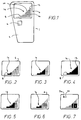
- a device 1 according to the invention is shown in Figure 1 and includes a body 2 in which an actuation button 4 and a display means 6 are mounted.
- the display means 6 comprises a series of columns 8, 10, 12 of light emitting diodes (LED's) 14.
- the column 12 at the right hand side of the display comprises eight LED's 14 and is the highest column and column 8 at the left hand side of the display comprise a single LED 14 and is one of the shortest columns.
- the intervening columns 10 are graded in height between the highest and lowest columns 12, 8.
- control means are provided which are described in outline below and which act to control illumination of the LED's 14 to produce an image 16. By selectively illuminating the LEDs, the image 16 can be made to grow and diminish or disappear completely.
- the main components of the control means 18 are shown schematically in Figure 8. These components comprise: a battery 20; a command button 4 (also shown in Figure 1); a power-up circuit 22; a command signal analyser (analyser) 24; a clock 26; a breaths per minute circuit 27; and a display signal generation circuit (display circuit) 30 which is connected to the LEDs 14 in the display means 6 by LED wires 32.
- the main electrical connections between these components are shown in Figure 8 with arrows indicating the direction of information or data flow along the connections.
- a display cycle frequency store 29 in the breaths per minute circuit 27 will contain data representing the number of breaths that the user should make per minute minus 1 (the display frequency) in a rested and relaxed state.
- the display circuit 30 will contain ratio information concerning duration ratios of first second and third displays which together constitute a display cycle.
- the duration ratio of the first, to the second, to the third display are 4:5:1 and correspond to inhalation, exhalation and resting respectively.
- the user depresses the button 4 which sends a signal from the battery 20 to the anaylser 24 which forwards a signal to the power-up circuit 22 thus switching it on causing power to be supplied to the clock 26, the breaths per minute circuit 27 and the display circuit 30.
- the analyser 24 will send a signal to the breaths per minute circuit 27 which will cause it to send a signal representing the display frequency from the display circuit frequency store 29 to the display circuit 30.
- the display circuit then combines the display frequency signal with a clocking signal from the clock 26 and the ratio information to generate signals which are transmitted along LED wires 32 to the LEDs 14 which are used to form the image 16 on the display means 6.
- the LEDs 14 shown in Figures 1 to 7 are shown shaded to represent an illuminated LED and blank to represent an unilluminated LED.
- the display means will initially be blank as shown in Figure 1. A steady growth of an image 16 will then occur. First the column 8 (comprising one LED only) will be illuminated. Successive columns to its right will then additionally become illuminated until the full image shown in Figure 4 has been formed. This growth of the image 16 constitutes the first display, has a duration t1 and corresponds to a period during which the user should be inhaling.
- the display means 6 remains unilluminated as shown in Figure 1 for a period t3.
- This unilluminated state constitutes the third display and corresponds to a period in which the user should be pausing before recommencing inhalation.
- the display circuit calculates the duration of t1, t2 and t3 such that:
- the button is depressed for a prolonged period, such as 3 seconds, after which a single LED 34 will become illuminated and the display frequency f will be displayed in numeric form.
- the display means 6 in Figure 7 shows a display frequency of 10 being displayed.
- the button 4 is depressed for over 3 seconds until the analyser 24 sends a signal to the display circuit causing it to illuminate two LEDs 34 and 35. When this occurs, the button 4 is released which causes the analyser 24 to actuate a breaths per minute computation means 28 in the breaths per minute circuit 27. The user then depresses the button 4 briefly at the end of each of five successive exhalations. The resulting signals are routed by the analyser 24 to the breaths per minute computation means 28 which computes the number of breaths which would be made by the user in a minute and display this number briefly on the display means.
- This number is changed to the measured number of breaths per minute by quick depressions of the button which results in signals being sent via the analyser 24 to the breaths per minute circuit 27.
- the button 4 is left released for a while.
- This results in the display frequency f being calculated by the breaths per minute computation means 28 (the measured number of breaths per minute minus 1) and stored in the display cycle frequency store 29.
- the device is then ready for the individual to use.
- the display frequency can be easily altered using the technique set out above.
- the device could be adapted to calculate and store the display frequency directly from the information input during the measurement of the relaxed breathing rate of the user.
Abstract
Description
Claims (14)
- Therapeutic device (1) for assisting in the lowering of a user's breathing rate the device comprising display means (6,14) and control means (18) adapted to operatively control the display means (6,14) so that it generates a repeating display cycle, each cycle including a first display followed by a second display corresponding respectively to periods of user inhalation and exhalation.
- A therapeutic device according to claim 1 wherein the control means (18) includes means to control the display means (6,14) so that each display cycle it generates further includes a third display which occurs after termination of the second display and before commencement of the subsequent first display and corresponds to a user rest period between exhalation and inhalation.
- A therapeutic device according to claim 1 or 2 further including adjusting means (4,24,27,28,29) for adjusting the period of display cycles generated by the control means (18).
- A therapeutic device according to claim 1, 2 or 3 wherein the control means (18) is able to provide information in character form on the display means (6,14) concerning the display cycle.
- A therapeutic device according to claim 4 wherein the information in character form comprises a number of display cycles per minute stored in the control means (18).
- A therapeutic device according to any preceding claim wherein the control means (18) includes ratio information storage means (30) which ratio information is used to determine the ratio of a duration of the first display to that of the second display.
- A therapeutic device according to claim 6 wherein the duration of the second display is longer than that of the first display.
- A therapeutic device according to claim 2 or any claim dependent thereon wherein in each cycle: the first display unit lasts for between 30% and 50%; the second display lasts for between 40% and 60%; and the third display lasts for Between 5% and 15% of the display cycle time.
- A therapeutic device according to claim 8 wherein in each cycle: the first display lasts for substantially 40%; the second display lasts for substantially 50%; and the third display lasts for substantially 10% of the display cycle time.
- A therapeutic device according to any preceding claim wherein the first display comprises a representation which grows and the second display comprises a shrinking of the representation.
- A therapeutic device according to claim 10 wherein the growing and shrinking occurs in a gradual or stepped manner.
- A therapeutic device according to claim 10 or 11 wherein the representation includes adjacent strips at least some of which differ in length.
- A therapeutic device according to any preceding claim wherein the device is adapted to be held in a user's hand.
- A therapeutic device according to claim 10 or 11 wherein the representation comprises a bar-like image.
Applications Claiming Priority (2)
| Application Number | Priority Date | Filing Date | Title |
|---|---|---|---|
| GBGB9626446.0A GB9626446D0 (en) | 1996-12-20 | 1996-12-20 | Therapeutic device |
| GB9626446 | 1996-12-20 |
Publications (2)
| Publication Number | Publication Date |
|---|---|
| EP0856334A2 true EP0856334A2 (en) | 1998-08-05 |
| EP0856334A3 EP0856334A3 (en) | 1999-05-12 |
Family
ID=10804729
Family Applications (1)
| Application Number | Title | Priority Date | Filing Date |
|---|---|---|---|
| EP97310327A Withdrawn EP0856334A3 (en) | 1996-12-20 | 1997-12-19 | Therapeutic device |
Country Status (2)
| Country | Link |
|---|---|
| EP (1) | EP0856334A3 (en) |
| GB (1) | GB9626446D0 (en) |
Cited By (12)
| Publication number | Priority date | Publication date | Assignee | Title |
|---|---|---|---|---|
| WO2000059580A1 (en) * | 1999-04-05 | 2000-10-12 | Schreiber Simeon B | Assistive breathing device |
| WO2001019245A1 (en) * | 1999-09-14 | 2001-03-22 | Boston Medical Technologies, Inc. | Method and apparatus for enhancing patient compliance during inspiration measurements |
| EP1538970A1 (en) * | 2002-08-09 | 2005-06-15 | Intercure Ltd. | Generalized metronome for modification of biorhythmic activity |
| EP1690493A1 (en) * | 2005-02-14 | 2006-08-16 | Tanita Corporation | Blood-pressure monitor |
| EP2022541A1 (en) | 2007-08-08 | 2009-02-11 | Heidrun Fehrl | Portable breath meter |
| DE102009007934A1 (en) * | 2009-02-06 | 2010-08-12 | Heidrun Fehrl | Portable breath |
| US8183453B2 (en) | 1999-07-06 | 2012-05-22 | Intercure Ltd. | Interventive-diagnostic device |
| US9642557B2 (en) | 2004-07-23 | 2017-05-09 | 2Breathe Technologies Ltd. | Apparatus and method for breathing pattern determination using a non-contact microphone |
| US10531827B2 (en) | 2002-12-13 | 2020-01-14 | 2Breathe Technologies Ltd. | Apparatus and method for beneficial modification of biorhythmic activity |
| WO2020146251A1 (en) * | 2019-01-07 | 2020-07-16 | Bose Corporation | Non-linear breath entrainment |
| WO2020146259A1 (en) * | 2019-01-07 | 2020-07-16 | Bose Corporation | Logic for modulating entrainment sequence with biofeedback |
| US11690530B2 (en) | 2017-08-21 | 2023-07-04 | Muvik Labs, Llc | Entrainment sonification techniques |
Citations (4)
| Publication number | Priority date | Publication date | Assignee | Title |
|---|---|---|---|---|
| GB935766A (en) * | 1959-10-27 | 1963-09-04 | Etienne Giordano | Apparatus for assisting a patient to develop a respiration cycle |
| US3424147A (en) * | 1965-03-25 | 1969-01-28 | Etienne Giordano | Apparatus for imposing a respiratory cycle to a patient |
| FR2599629A1 (en) * | 1986-06-09 | 1987-12-11 | Bruey Sa Electro Meca Precisio | Device for timing pulmonary respiration of an individual at a predetermined rate |
| WO1994014374A1 (en) * | 1992-12-24 | 1994-07-07 | Peter Bernard Defares | An interactive respiratory regulator |
-
1996
- 1996-12-20 GB GBGB9626446.0A patent/GB9626446D0/en active Pending
-
1997
- 1997-12-19 EP EP97310327A patent/EP0856334A3/en not_active Withdrawn
Patent Citations (4)
| Publication number | Priority date | Publication date | Assignee | Title |
|---|---|---|---|---|
| GB935766A (en) * | 1959-10-27 | 1963-09-04 | Etienne Giordano | Apparatus for assisting a patient to develop a respiration cycle |
| US3424147A (en) * | 1965-03-25 | 1969-01-28 | Etienne Giordano | Apparatus for imposing a respiratory cycle to a patient |
| FR2599629A1 (en) * | 1986-06-09 | 1987-12-11 | Bruey Sa Electro Meca Precisio | Device for timing pulmonary respiration of an individual at a predetermined rate |
| WO1994014374A1 (en) * | 1992-12-24 | 1994-07-07 | Peter Bernard Defares | An interactive respiratory regulator |
Cited By (20)
| Publication number | Priority date | Publication date | Assignee | Title |
|---|---|---|---|---|
| US6436053B1 (en) | 1997-10-01 | 2002-08-20 | Boston Medical Technologies, Inc. | Method and apparatus for enhancing patient compliance during inspiration measurements |
| US6740046B2 (en) | 1997-10-01 | 2004-05-25 | Boston Medical Technologies, Inc. | Method and apparatus for enhancing patient compliance during inspiration measurements |
| WO2000059580A1 (en) * | 1999-04-05 | 2000-10-12 | Schreiber Simeon B | Assistive breathing device |
| US8183453B2 (en) | 1999-07-06 | 2012-05-22 | Intercure Ltd. | Interventive-diagnostic device |
| US10314535B2 (en) | 1999-07-06 | 2019-06-11 | 2Breathe Technologies Ltd. | Interventive-diagnostic device |
| US9446302B2 (en) | 1999-07-06 | 2016-09-20 | 2Breathe Technologies Ltd. | Interventive-diagnostic device |
| US8658878B2 (en) | 1999-07-06 | 2014-02-25 | Intercure Ltd. | Interventive diagnostic device |
| WO2001019245A1 (en) * | 1999-09-14 | 2001-03-22 | Boston Medical Technologies, Inc. | Method and apparatus for enhancing patient compliance during inspiration measurements |
| US10576355B2 (en) | 2002-08-09 | 2020-03-03 | 2Breathe Technologies Ltd. | Generalized metronome for modification of biorhythmic activity |
| EP1538970A4 (en) * | 2002-08-09 | 2010-12-08 | Intercure Ltd | Generalized metronome for modification of biorhythmic activity |
| EP1538970A1 (en) * | 2002-08-09 | 2005-06-15 | Intercure Ltd. | Generalized metronome for modification of biorhythmic activity |
| US10531827B2 (en) | 2002-12-13 | 2020-01-14 | 2Breathe Technologies Ltd. | Apparatus and method for beneficial modification of biorhythmic activity |
| US9642557B2 (en) | 2004-07-23 | 2017-05-09 | 2Breathe Technologies Ltd. | Apparatus and method for breathing pattern determination using a non-contact microphone |
| EP1690493A1 (en) * | 2005-02-14 | 2006-08-16 | Tanita Corporation | Blood-pressure monitor |
| EP2022541A1 (en) | 2007-08-08 | 2009-02-11 | Heidrun Fehrl | Portable breath meter |
| DE102009007934A1 (en) * | 2009-02-06 | 2010-08-12 | Heidrun Fehrl | Portable breath |
| US11690530B2 (en) | 2017-08-21 | 2023-07-04 | Muvik Labs, Llc | Entrainment sonification techniques |
| WO2020146251A1 (en) * | 2019-01-07 | 2020-07-16 | Bose Corporation | Non-linear breath entrainment |
| WO2020146259A1 (en) * | 2019-01-07 | 2020-07-16 | Bose Corporation | Logic for modulating entrainment sequence with biofeedback |
| US11617917B2 (en) | 2019-01-07 | 2023-04-04 | Bose Corporation | Non-linear breath entrainment |
Also Published As
| Publication number | Publication date |
|---|---|
| EP0856334A3 (en) | 1999-05-12 |
| GB9626446D0 (en) | 1997-02-05 |
Similar Documents
| Publication | Publication Date | Title |
|---|---|---|
| EP0856334A2 (en) | Therapeutic device | |
| US6212135B1 (en) | Assistive breathing device | |
| US20030065272A1 (en) | Respiratory timing and lung deflation device | |
| JP5081252B2 (en) | Brain function maintenance improvement device | |
| CN104665785B (en) | Physiological feedback system | |
| CN102056536A (en) | Method and system for maintaining a state in a subject | |
| US20060184052A1 (en) | Blood-pressure monitor | |
| CN104665787B (en) | Physiological feedback system | |
| US20050240108A1 (en) | Chair or bed member having data storage | |
| JP4378957B2 (en) | Physiological state induction device | |
| JP2002330933A (en) | Instrument for measuring quantity of motion | |
| JP2005137896A (en) | Relaxation system, relaxation method and relaxation program | |
| AU2001295347A1 (en) | Chair or bed member having data storage | |
| CN104665789A (en) | Biofeedback system | |
| CN104667487A (en) | Biofeedback system | |
| CN104667486A (en) | Biofeedback system | |
| CN110764622A (en) | Virtual reality multi-mode speech training instrument | |
| CN204839482U (en) | Illuminator and use this illuminator's physiology feedback system | |
| CN204813837U (en) | Physiology feedback system | |
| CN204839484U (en) | Physiology feedback system | |
| CN204839481U (en) | Physiology feedback system | |
| US7507206B2 (en) | Stress reducer | |
| US20230233099A1 (en) | Breath guide device and method | |
| JP2019083979A (en) | Oxygen concentrator | |
| CN110097943A (en) | A kind of insomnia rehabilitation system that body-building is combined with medical treatment |
Legal Events
| Date | Code | Title | Description |
|---|---|---|---|
| PUAI | Public reference made under article 153(3) epc to a published international application that has entered the european phase |
Free format text: ORIGINAL CODE: 0009012 |
|
| AK | Designated contracting states |
Kind code of ref document: A2 Designated state(s): AT BE CH DE DK ES FI FR GB GR IE IT LI LU MC NL PT SE |
|
| AX | Request for extension of the european patent |
Free format text: AL;LT;LV;MK;RO;SI |
|
| PUAL | Search report despatched |
Free format text: ORIGINAL CODE: 0009013 |
|
| AK | Designated contracting states |
Kind code of ref document: A3 Designated state(s): AT BE CH DE DK ES FI FR GB GR IE IT LI LU MC NL PT SE |
|
| AX | Request for extension of the european patent |
Free format text: AL;LT;LV;MK;RO;SI |
|
| AKX | Designation fees paid | ||
| REG | Reference to a national code |
Ref country code: DE Ref legal event code: 8566 |
|
| STAA | Information on the status of an ep patent application or granted ep patent |
Free format text: STATUS: THE APPLICATION IS DEEMED TO BE WITHDRAWN |
|
| 18D | Application deemed to be withdrawn |
Effective date: 19991113 |