EP0809172A2 - Wearable computer - Google Patents
Wearable computer Download PDFInfo
- Publication number
- EP0809172A2 EP0809172A2 EP97302385A EP97302385A EP0809172A2 EP 0809172 A2 EP0809172 A2 EP 0809172A2 EP 97302385 A EP97302385 A EP 97302385A EP 97302385 A EP97302385 A EP 97302385A EP 0809172 A2 EP0809172 A2 EP 0809172A2
- Authority
- EP
- European Patent Office
- Prior art keywords
- unit
- coupled
- transceiver
- leds
- recited
- Prior art date
- Legal status (The legal status is an assumption and is not a legal conclusion. Google has not performed a legal analysis and makes no representation as to the accuracy of the status listed.)
- Granted
Links
Images


Classifications
-
- G—PHYSICS
- G06—COMPUTING; CALCULATING OR COUNTING
- G06F—ELECTRIC DIGITAL DATA PROCESSING
- G06F1/00—Details not covered by groups G06F3/00 - G06F13/00 and G06F21/00
- G06F1/16—Constructional details or arrangements
-
- G—PHYSICS
- G06—COMPUTING; CALCULATING OR COUNTING
- G06F—ELECTRIC DIGITAL DATA PROCESSING
- G06F1/00—Details not covered by groups G06F3/00 - G06F13/00 and G06F21/00
- G06F1/16—Constructional details or arrangements
- G06F1/1613—Constructional details or arrangements for portable computers
- G06F1/163—Wearable computers, e.g. on a belt
Definitions
- the present invention relates in general to data processing systems, and in particular, to a wearable computer with a hand-held display device.
- Typical hand-held computers that are rich in function and long in battery life are cumbersome and heavy.
- Functions such as bar code scanners, hard files, batteries, wireless LAN (local area network) adapters, etc. take up space and have considerable weight. This makes long-term use of these devices tiring to the user.
- the present invention satisfies the foregoing need by mounting the processor, hard files; adapter cards, antenna, batteries, and all other computer-associated components, except for the display, which could include touch, pen or voice input, on a user's belt, backpack, or any other wearable accessory.
- the display and touch screen can be packaged in a separate ultra-lightweight unit that the operator can hold.
- Communication between the wearable computer and the hand-held display may be achieved by a wireless link, such as a four-colour optical link, high speed infrared link, or a short range RF link.
- the present invention can also be used within a wireless network (LAN or WAN (wide area network)) by providing for wireless radio (RF) communications between the wearable computer and a computer server also employing RF communications equipment.
- LAN or WAN wide area network
- RF wireless radio
- the hand-held display package When not in use, the hand-held display package can be mounted to the wearable computer for storage. Additionally, with such a storage configuration, electrical terminals can be provided so that a larger power supply associated with the wearable computer can charge a smaller battery pack powering the hand-held display package.
- Wearable unit 113 of the computer which may include the central processing unit (CPU), memory and storage devices, adapter cards, communications antenna, power supply/batteries, display adapter, and other computer-associated components, except for the display and touch screen, are mounted on belt 20 attached to the user.
- Display circuitry and touch screen 138 are mounted within display package 195, which is shown being held by the user.
- antenna 167 coupled to wearable unit 113, which, as described further below, is adaptable for permitting wireless communications between the wearable computer and a wireless network or other communications link.
- a special high-speed optical link allows unit 113 to communicate wirelessly with display package 195.
- the distance between unit 113 and display package 195 can be at an arm's length, so it will be possible to achieve data rates necessary to control display device 138, such as a flat panel display device, e.g., a liquid crystal colour VGA screen, a field emission display (FED), a plasma screen, etc.
- a battery (not shown) is used within display package 195 to provide power to the display circuitry.
- Unit 113 comprises CPU 110 coupled by system bus 112 to read only memory (ROM) 116, random access memory (RAM) 114, input/output (I/O) adapter 118, communications adapter 134, and display adapter 185.
- ROM read only memory
- RAM random access memory
- I/O input/output
- communications adapter 134 communications adapter 134
- display adapter 185 display adapter 185.
- I/O adapter 118 couples bus 112 to such storage devices as hard disk or optical disk 120, and tape storage 140.
- Transceiver 165 is operable for transmitting and receiving RF radio signals via antenna 167 to a corresponding transceiver and antenna associated with a network server (not shown), as discussed below with respect to FIGURE 3.
- a network server not shown
- an optical or other wireless link, or a wired link may also be used for communications with the network server.
- Power is supplied to unit 113 by power supply 101, which may utilise some type of battery 103. Power from battery 103 is supplied via link 102, which may be a part of bus 112.
- Display package 195 includes optical link transceiver 180 coupled to display interface 186 and user interface adapter 190.
- User interface adapter 190 and display interface 186 are coupled to display screen 138, which may be a touch screen operable for permitting input to the computer by a user.
- user interface adapter 190 may include a touch controller.
- Battery 196 coupled to each of the aforementioned portions of display package 195 supplies power to these portions.
- Battery 196 may be smaller than battery 101 to maintain the lightweight characteristic of display package 195.
- Communications between display package 195 and unit 113 is performed via optical link circuitry.
- Optical link transceiver 180 may include one or more light emitting diodes ("LEDs") 27 for converting electrical signals into optical signals to be transmitted for detection by one or more photodetectors 25 coupled to optical link transceiver 160.
- optical link transceiver 160 may include one or more LEDs 21 operable for converting electrical signals carrying video and control information for transmission and reception by one or more photodetectors 26 coupled to optical link transceiver 180.
- solid state lasers could be used instead of LEDs.
- Photodetectors 25 and 26 operate to convert the received optical signals into electrical signals carrying video and/or control information.
- Display adapter 185 can use a standard video display controller chip 1000, which can be used to drive display 138 with standard video signals: red, green, blue, horizontal sync (H sync) and vertical sync (V sync). Such chips output digital sync pulses, but the colour signals are analog.
- Video display controller chip 1000 includes analog circuitry 1001 for outputting the red, green and blue analog signals and circuitry 1002 for outputting the digital horizontal and vertical sync signals.
- FIGURE 10 also illustrates a portion of optical link transceiver 160 for converting the colour and sync outputs from circuits 1001 and 1002, respectively, into optical signals to be transmitted to optical link transceiver 180, a portion of which is also illustrated in FIGURE 10.
- the red, green and blue colour signals are received by LED drive circuits 1003-1005, respectively, which drive LEDs 21 comprised of LED 1006 for transmitting the red colour signal via a red light, LED 1007 for transmitting the green colour signal using a green light, and LED 1008 for transmitting the blue colour signal using a yellow light.
- Receipt of such optical signals from red, green, and yellow diodes 21 is done by corresponding photodetectors 26 in display package 195.
- composite sync signal that contains both horizontal and vertical sync information. This may be performed by using composite sync generating circuit 1015 and driving LED 1016 to transmit the information using infrared (I) light.
- I infrared
- four different colour LEDs 21 could be used to transmit the video signals from unit 113 to four photodetectors 26 in display package 195.
- Interference-type filters 401 can be placed in front of each of photodetector 26 to insure that the red signal is only received by the photodetector designated for the red signal, etc.
- the red light from LED 1006 is passed through red interference filter 1009 and received by photodetector 1012 to reproduce the red colour signal.
- the green light from LED 1007 is passed through green interference filter 1010 and received by photodetector 1013 to reproduce the green colour signal.
- the yellow light is received from LED 1008 and passed through yellow interference filter 1011 to be received by photodetector 1014 to reproduce the blue colour signal.
- the infrared light signal received from LED 1016 is passed through infrared interference filter 1017 to be received by photodetector 1018 to reproduce the composite sync signal.
- Such interference filters 401 are available from Mellis Griot, Inc., with wavelength bandpasses that cut off within ten nanometers. This is more than adequate for isolating red from green from yellow from infrared LED light. Alternatively, other light wavelength selective filters could be used.
- the amplitude of the digital signal from composite sync generating circuit 1015 is not important (within a reasonable range), so this signal can drive infrared LED 1016 directly, without gain control.
- LEDs 1006-1008 transmitting the colour signals may be operated in a linear mode so that the analog signals could be transmitted. Coloured LEDs are commercially available with adequate bandwidth, but the end-to-end gain may be controlled, as further described below with respect to FIGURE 4.
- Non-video data could be included in the communications between unit 113 and display package 195. This data could be placed in the sync signal during the "vertical interval" time. The vertical interval time is when display 138 is normally moving the electron beam back to the starting corner of display 138. This technique is used in TV signals to enable information such as written captions to be transmitted with the normal signal. The information could be such things as diagnostic commands, scanner control, and optical link gain control for analog signals.
- display package-to-wearable unit data could be sent via a fifth optical link, pointed in the opposite direction.
- This link could use any colour light for LED 27 since its light source will not be seen by optical detectors 26. Reception of light from LED 27 is performed by photodetector(s) 25.
- circuitry described above with respect to FIGURE 10 may also be used for implementing the optical link from LEDs 27 to photodetectors 25.
- FIGURE 4 there is shown photodetector/amplifier/gain control circuit 40 utilised with respect to each of photodetectors 25 and 26. Since the red, green and blue video signals are analog signals, the end-to-end gain of the optical link must be monitored and controlled. This is especially true since display package 195 will move in relation to wearable computer 113.
- Gain control can be achieved by placing a gain calibration pulse on the analog video signals during the vertical interval time.
- Each of the red, green and yellow light source LEDs would be pulsed at a level that should represent a predefined voltage at the end of the photodetector amplifier chain. Since this is done during the vertical interval time, the displayed information will not be affected.
- a gain setting sync pulse would be placed on the digital composite sync signal to indicate when the analog signal should be sampled by gain control circuitry 40 associated with each of photodetectors 26. This signal would be recovered by gain control circuitry 40 and labelled "+gain sample time" with it being an open collector driver that is turned off when the gain signal is to be sampled.
- Gain control circuitry 40 then samples the recovered analog signals during the indicated sample time within every vertical interval, which is at 60 times a second or greater. This is frequent enough to compensate for movement of display package 195 relative to unit 113 when the user is holding display package 195.
- circuits 40 There would be three of circuits 40, one for red, one for green, and one for blue (yellow).
- the incoming analog optical colour signal (red, green or yellow) is first filtered by an optical filter 401 to ensure that only the desired signal is received.
- the optical signal is then converted to an electrical signal by photodiode 403.
- the electrical signal is then amplified by amplifier 405, whose gain can be externally controlled by means of an analog signal through gain control input 413.
- the output of amplifier 405 is the recovered analog colour signal.
- the recovered analog colour signal is then sampled via resistor 406 by a peak follower circuit if the signal (+gain sample time) is not held down by its open collector driver.
- the peak follower circuit made up of amplifier 407, diode 408, and capacitor 411 will store the maximum level of the recovered analog signal during the sample time.
- the time constant of capacitor 411 and resistor 410 is such that the voltage on capacitor 411 is relatively stable during the time between gain samples.
- Error amplifier 412 compares the actual signal size stored on capacitor 411 with a reference voltage Vref and provides an error signal. The error signal will be larger if the gain needs to increase. The error signal is then what controls the gain of amplifier 405 via gain control input 413.
- the recovered analog colour signals are then digitized by analog-to-digital (A/D) converters 450.
- the digital colour signals would then be used to control display 138.
- FIGURES 3 and 7 there is illustrated use of the present invention within a local area network (LAN).
- Data is transmitted between wearable computer 113 (which, in FIGURE 3 is shown to be mounted to belt 20) via antenna 167 and transceiver 165 to/from antenna 33 and transceiver 32,which is connected to base station/access point 31.
- Base station/access point 31 communicates these data communications to computer server 30.
- FIGURES 5 and 6 there is illustrated an alternative embodiment of the present invention.
- antenna 167 When one antenna 167 is used for communicating with antenna 33 illustrated in FIGURE 3, there is the possibility that the user may be positioned so that there is a notch in the propagation pattern emanating from antenna 167 as a result of the user's body blocking the path between antennas 167 and 33.
- a solution to this problem is the use of two antennas 50 and 51. Patch type antennas would be good for this. Generally, such antennas are directional, flat antennas having an approximate 180 degrees RF pattern. It is not unusual for wireless LAN systems to have the capability for antenna diversity, i.e., the ability to utilise two antennas.
- Antennas 50 and 51 are coupled to wearable computer 113 via transmission lines 60 and 61.
- Antennas 50 and 51 may be positioned on belt 20 on opposite sides of the user (or some other location on the user) so that the propagation patterns 52 and 53 overlap resulting in the absence of any notch within the propagation pattern emanating from the antennas 50 and 51.
- FIGURE 6 illustrates that the use of two antennas 50 and 51 may be used within such a wearable computer where display package 195 is coupled to unit 113 by tethered line 62 transmitting the power and data signals to and from unit 113 and display package 195, instead of the previously described optical method.
- tethered line 62 could be a fibre optic cable.
- FIGURE 7 there is illustrated a rear view of unit 113 having belt clip 70 attached thereto so that unit 113 can be attached to belt 20.
- inboard antenna 71 mounted within recess 72 of unit 113, as opposed to the extension of antenna 167 shown in FIGURE 3.
- FIGURE 8 there is illustrated the mounting of display package 195 onto wearable computer 113 through the use of clip 80, adaptable for attaching and holding display package 195.
- clips 80 for attaching two devices together are well-known in the art.
- FIGURE 9 there is illustrated display package 195 attached to unit 113 by clips 80 and 90. Electrical contacts 91-94 are in physical contact with each other when display package 195 is clipped to unit 113 so that battery 103 within unit 113 may supply power to recharge battery 196 within display package 195.
- holster 1101 mounted to belt 1100 for receiving and storing unit 113. Power could be supplied to unit 113 via holster 1101 in a manner similar to that described above with respect to FIGURE 9.
- Unit 195 could be part of holster.
- unit 113 worn by a user utilising over-the-shoulder belt 1200.
- unit 195 is worn by the user utilising neck strap 1300.
- display package 113 is not shown for reasons of clarity.
- unit 195 may be worn by a user in many other fashions, such as with a backpack or some type of head gear.
- unit 113 may be modified by one skilled in the art to include a bar code scanner and/or an RFID tag reader.
Abstract
Description
- The present invention relates in general to data processing systems, and in particular, to a wearable computer with a hand-held display device.
- In recent years, because of the fast development in electronic technology, computers have become faster in operation and more compact in structure. Because they are high performance, low cost and easy to carry, portable and hand-held personal computers have become more and more popular.
- Typical hand-held computers that are rich in function and long in battery life are cumbersome and heavy. Functions such as bar code scanners, hard files, batteries, wireless LAN (local area network) adapters, etc. take up space and have considerable weight. This makes long-term use of these devices tiring to the user.
- Thus, there is a need in the art for a hand-held computer that is more lightweight for the user to hold for long periods of time.
- The present invention satisfies the foregoing need by mounting the processor, hard files; adapter cards, antenna, batteries, and all other computer-associated components, except for the display, which could include touch, pen or voice input, on a user's belt, backpack, or any other wearable accessory. The display and touch screen can be packaged in a separate ultra-lightweight unit that the operator can hold. Communication between the wearable computer and the hand-held display may be achieved by a wireless link, such as a four-colour optical link, high speed infrared link, or a short range RF link.
- The present invention can also be used within a wireless network (LAN or WAN (wide area network)) by providing for wireless radio (RF) communications between the wearable computer and a computer server also employing RF communications equipment. The use of two patch antennas mounted on opposite sides of the person's body eliminates any gaps in the propagation pattern emanated from the transceiver coupled to the wearable computer.
- When not in use, the hand-held display package can be mounted to the wearable computer for storage. Additionally, with such a storage configuration, electrical terminals can be provided so that a larger power supply associated with the wearable computer can charge a smaller battery pack powering the hand-held display package.
- For a more complete understanding of the present invention, and the advantages thereof, reference is now made to the following description taken in conjunction with the accompanying drawings, in which:
- FIGURE 1 illustrates, in block diagram form, an embodiment of the present invention;
- FIGURE 2 illustrates a user holding an embodiment of the present invention;
- FIGURE 3 illustrates use of the present invention within a LAN;
- FIGURE 4 illustrates a circuit diagram of a photodetector-amplifier-gain control circuit used in the present invention;
- FIGURE 5 illustrates propagation patterns of the use of two antennas in conjunction with the present invention;
- FIGURE 6 further illustrates the two antenna embodiment illustrated in FIGURE 5;
- FIGURE 7 illustrates a belt clip for mounting the present invention on a belt;
- FIGURE 8 illustrates the mounting of the display unit with the main computer unit;
- FIGURE 9 illustrates an apparatus for recharging batteries within the display unit;
- FIGURE 10 illustrates in partial block diagram form and partial circuit diagram form an optical link in accordance with one embodiment of the present invention;
- FIGURE 11 illustrates use of a holster to carry the present invention;
- FIGURE 12 illustrates use of an over-the-shoulder strap to carry the present invention; and
- FIGURE 13 illustrates use of a neck strap to carry the present invention.
- In the following description, numerous specific details are set forth to provide a thorough understanding of the present invention. However, it will be obvious to those skilled in the art that the present invention may be practised without such specific details. In other instances, well-known circuits have been shown in block diagram form in order not to obscure the present invention in unnecessary detail. For the most part, details concerning timing considerations and the like have been omitted inasmuch as such details are not necessary to obtain a complete understanding of the present invention and are within the skills of persons of ordinary skill in the relevant art.
- Refer now to the drawings wherein depicted elements are not necessarily shown to scale and wherein like or similar elements are designated by the same reference numeral through the several views.
- Referring to FIGURE 2, there is illustrated a user holding an embodiment of the present invention.
Wearable unit 113 of the computer, which may include the central processing unit (CPU), memory and storage devices, adapter cards, communications antenna, power supply/batteries, display adapter, and other computer-associated components, except for the display and touch screen, are mounted onbelt 20 attached to the user. Display circuitry andtouch screen 138 are mounted withindisplay package 195, which is shown being held by the user. - Also shown is
antenna 167 coupled towearable unit 113, which, as described further below, is adaptable for permitting wireless communications between the wearable computer and a wireless network or other communications link. - In the embodiment shown in FIGURE 2, a special high-speed optical link allows
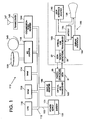
unit 113 to communicate wirelessly withdisplay package 195. The distance betweenunit 113 anddisplay package 195 can be at an arm's length, so it will be possible to achieve data rates necessary to controldisplay device 138, such as a flat panel display device, e.g., a liquid crystal colour VGA screen, a field emission display (FED), a plasma screen, etc. A battery (not shown) is used withindisplay package 195 to provide power to the display circuitry. - Referring next to FIGURE 1, there is shown a block diagram of the wearable computer illustrated in FIGURE 2.
Unit 113 comprisesCPU 110 coupled bysystem bus 112 to read only memory (ROM) 116, random access memory (RAM) 114, input/output (I/O)adapter 118,communications adapter 134, anddisplay adapter 185. - I/
O adapter 118couples bus 112 to such storage devices as hard disk oroptical disk 120, andtape storage 140. -
Communications adapter 134, is coupled to transceiver 165.Transceiver 165 is operable for transmitting and receiving RF radio signals viaantenna 167 to a corresponding transceiver and antenna associated with a network server (not shown), as discussed below with respect to FIGURE 3. Alternatively, an optical or other wireless link, or a wired link may also be used for communications with the network server. - Power is supplied to
unit 113 bypower supply 101, which may utilise some type ofbattery 103. Power frombattery 103 is supplied vialink 102, which may be a part ofbus 112. -
Display package 195 includesoptical link transceiver 180 coupled to display interface 186 anduser interface adapter 190.User interface adapter 190 and display interface 186 are coupled to displayscreen 138, which may be a touch screen operable for permitting input to the computer by a user. To facilitate such a touch screen,user interface adapter 190 may include a touch controller. -
Battery 196 coupled to each of the aforementioned portions ofdisplay package 195 supplies power to these portions.Battery 196 may be smaller thanbattery 101 to maintain the lightweight characteristic ofdisplay package 195. - Communications between
display package 195 andunit 113 is performed via optical link circuitry. -
Optical link transceiver 180 may include one or more light emitting diodes ("LEDs") 27 for converting electrical signals into optical signals to be transmitted for detection by one ormore photodetectors 25 coupled tooptical link transceiver 160. Likewise,optical link transceiver 160 may include one ormore LEDs 21 operable for converting electrical signals carrying video and control information for transmission and reception by one ormore photodetectors 26 coupled tooptical link transceiver 180. Alternatively, solid state lasers could be used instead of LEDs.Photodetectors - Referring next to FIGURE 10, there is shown one embodiment for the optical link circuitry. Display adapter 185 (Fig. 1) can use a standard video
display controller chip 1000, which can be used to drivedisplay 138 with standard video signals: red, green, blue, horizontal sync (H sync) and vertical sync (V sync). Such chips output digital sync pulses, but the colour signals are analog. - Video
display controller chip 1000 includesanalog circuitry 1001 for outputting the red, green and blue analog signals andcircuitry 1002 for outputting the digital horizontal and vertical sync signals. - FIGURE 10 also illustrates a portion of
optical link transceiver 160 for converting the colour and sync outputs fromcircuits optical link transceiver 180, a portion of which is also illustrated in FIGURE 10. - The red, green and blue colour signals are received by LED drive circuits 1003-1005, respectively, which drive
LEDs 21 comprised ofLED 1006 for transmitting the red colour signal via a red light, LED 1007 for transmitting the green colour signal using a green light, andLED 1008 for transmitting the blue colour signal using a yellow light. - Receipt of such optical signals from red, green, and
yellow diodes 21 is done bycorresponding photodetectors 26 indisplay package 195. - It is possible to create a composite sync signal that contains both horizontal and vertical sync information. This may be performed by using composite
sync generating circuit 1015 and drivingLED 1016 to transmit the information using infrared (I) light. Thus, fourdifferent colour LEDs 21 could be used to transmit the video signals fromunit 113 to fourphotodetectors 26 indisplay package 195. Interference-type filters 401 can be placed in front of each ofphotodetector 26 to insure that the red signal is only received by the photodetector designated for the red signal, etc. Thus, the red light fromLED 1006 is passed throughred interference filter 1009 and received byphotodetector 1012 to reproduce the red colour signal. The green light from LED 1007 is passed throughgreen interference filter 1010 and received byphotodetector 1013 to reproduce the green colour signal. And, the yellow light is received fromLED 1008 and passed throughyellow interference filter 1011 to be received byphotodetector 1014 to reproduce the blue colour signal. Likewise, the infrared light signal received fromLED 1016 is passed throughinfrared interference filter 1017 to be received byphotodetector 1018 to reproduce the composite sync signal. - Such interference filters 401 are available from Mellis Griot, Inc., with wavelength bandpasses that cut off within ten nanometers. This is more than adequate for isolating red from green from yellow from infrared LED light. Alternatively, other light wavelength selective filters could be used.
- The amplitude of the digital signal from composite
sync generating circuit 1015 is not important (within a reasonable range), so this signal can driveinfrared LED 1016 directly, without gain control. LEDs 1006-1008 transmitting the colour signals may be operated in a linear mode so that the analog signals could be transmitted. Coloured LEDs are commercially available with adequate bandwidth, but the end-to-end gain may be controlled, as further described below with respect to FIGURE 4. - Non-video data could be included in the communications between
unit 113 anddisplay package 195. This data could be placed in the sync signal during the "vertical interval" time. The vertical interval time is whendisplay 138 is normally moving the electron beam back to the starting corner ofdisplay 138. This technique is used in TV signals to enable information such as written captions to be transmitted with the normal signal. The information could be such things as diagnostic commands, scanner control, and optical link gain control for analog signals. - Referring back to FIGURE 1, display package-to-wearable unit data could be sent via a fifth optical link, pointed in the opposite direction. This link could use any colour light for
LED 27 since its light source will not be seen byoptical detectors 26. Reception of light fromLED 27 is performed by photodetector(s) 25. - The circuitry described above with respect to FIGURE 10 may also be used for implementing the optical link from
LEDs 27 tophotodetectors 25. - Referring next to FIGURE 4, there is shown photodetector/amplifier/
gain control circuit 40 utilised with respect to each ofphotodetectors display package 195 will move in relation towearable computer 113. - Gain control can be achieved by placing a gain calibration pulse on the analog video signals during the vertical interval time. Each of the red, green and yellow light source LEDs would be pulsed at a level that should represent a predefined voltage at the end of the photodetector amplifier chain. Since this is done during the vertical interval time, the displayed information will not be affected. A gain setting sync pulse would be placed on the digital composite sync signal to indicate when the analog signal should be sampled by
gain control circuitry 40 associated with each ofphotodetectors 26. This signal would be recovered bygain control circuitry 40 and labelled "+gain sample time" with it being an open collector driver that is turned off when the gain signal is to be sampled. -
Gain control circuitry 40 then samples the recovered analog signals during the indicated sample time within every vertical interval, which is at 60 times a second or greater. This is frequent enough to compensate for movement ofdisplay package 195 relative tounit 113 when the user is holdingdisplay package 195. - There would be three of
circuits 40, one for red, one for green, and one for blue (yellow). The incoming analog optical colour signal (red, green or yellow) is first filtered by anoptical filter 401 to ensure that only the desired signal is received. The optical signal is then converted to an electrical signal byphotodiode 403. The electrical signal is then amplified byamplifier 405, whose gain can be externally controlled by means of an analog signal throughgain control input 413. The output ofamplifier 405 is the recovered analog colour signal. - The recovered analog colour signal is then sampled via
resistor 406 by a peak follower circuit if the signal (+gain sample time) is not held down by its open collector driver. The peak follower circuit, made up ofamplifier 407,diode 408, andcapacitor 411 will store the maximum level of the recovered analog signal during the sample time. The time constant ofcapacitor 411 andresistor 410 is such that the voltage oncapacitor 411 is relatively stable during the time between gain samples. -
Error amplifier 412 compares the actual signal size stored oncapacitor 411 with a reference voltage Vref and provides an error signal. The error signal will be larger if the gain needs to increase. The error signal is then what controls the gain ofamplifier 405 viagain control input 413. - The recovered analog colour signals are then digitized by analog-to-digital (A/D)
converters 450. The digital colour signals would then be used to controldisplay 138. - Referring next to FIGURES 3 and 7, there is illustrated use of the present invention within a local area network (LAN). Data is transmitted between wearable computer 113 (which, in FIGURE 3 is shown to be mounted to belt 20) via
antenna 167 andtransceiver 165 to/fromantenna 33 andtransceiver 32,which is connected to base station/access point 31. Base station/access point 31 communicates these data communications tocomputer server 30. - Referring next to FIGURES 5 and 6, there is illustrated an alternative embodiment of the present invention.
- When one
antenna 167 is used for communicating withantenna 33 illustrated in FIGURE 3, there is the possibility that the user may be positioned so that there is a notch in the propagation pattern emanating fromantenna 167 as a result of the user's body blocking the path betweenantennas antennas Antennas wearable computer 113 viatransmission lines Antennas belt 20 on opposite sides of the user (or some other location on the user) so that thepropagation patterns antennas - Note, FIGURE 6 illustrates that the use of two
antennas display package 195 is coupled tounit 113 by tetheredline 62 transmitting the power and data signals to and fromunit 113 anddisplay package 195, instead of the previously described optical method. Alternatively, tetheredline 62 could be a fibre optic cable. - Referring next to FIGURE 7, there is illustrated a rear view of
unit 113 havingbelt clip 70 attached thereto so thatunit 113 can be attached tobelt 20. - Also shown is inboard
antenna 71 mounted withinrecess 72 ofunit 113, as opposed to the extension ofantenna 167 shown in FIGURE 3. - Referring next to FIGURE 8, there is illustrated the mounting of
display package 195 ontowearable computer 113 through the use ofclip 80, adaptable for attaching and holdingdisplay package 195.Such clips 80 for attaching two devices together are well-known in the art. - Referring next to FIGURE 9, there is illustrated
display package 195 attached tounit 113 byclips display package 195 is clipped tounit 113 so thatbattery 103 withinunit 113 may supply power to rechargebattery 196 withindisplay package 195. - Referring next to FIGURE 11, there is illustrated
holster 1101 mounted to belt 1100 for receiving and storingunit 113. Power could be supplied tounit 113 viaholster 1101 in a manner similar to that described above with respect to FIGURE 9.Unit 195 could be part of holster. - Referring next to FIGURE 12, there is illustrated
unit 113 worn by a user utilising over-the-shoulder belt 1200. - In FIGURE 13,
unit 195 is worn by the user utilisingneck strap 1300. - In FIGURES 12-13,
display package 113 is not shown for reasons of clarity. Furthermore,unit 195 may be worn by a user in many other fashions, such as with a backpack or some type of head gear. - Though not shown in the figures,
unit 113 may be modified by one skilled in the art to include a bar code scanner and/or an RFID tag reader. - In addition to the features recited in the patent claims various combinations of features of the present invention are identified as follows:
- 1. A data processing system comprising:
- a first unit (113) adaptable for wearing by a user, wherein said first unit includes a processor (110;
- a second unit (195) physically separate from said first unit, wherein said second unit includes an input or output device (138); and
- an optical link (180) for enabling said first unit to communicate with said second unit
- 2. The data processing system as recited in 1 above, further comprising: a second RF transceiver and antenna operable for communicating with said first RF transceiver; and
a server computer coupled to said second RF transceiver and antenna, wherein said server computer is capable of communicating with said processor via said first and second RF transceivers and antennas. - 3. The data processing system as recited in 2 above, further comprising: means for physically attaching said second unit to said first unit.
- 4. The data processing system as recited in 3 above, further comprising:
means for supplying electrical power from said first unit to said second unit when said second unit is physically attached to said first unit. - 5. The data processing system as recited in above, wherein said optical link includes one or more photodetectors which each further comprise a gain control circuit, said gain control circuit comprising:
- a photodiode;
- a first amplifier having an input coupled to said photodiode;
- a peak follower circuit coupled to an output of said first amplifier; and
- a second amplifier having a first input coupled to an output of said peak follower circuit and a second input coupled to a reference signal, wherein an output of said second amplifier is operable for controlling a gain of said first amplifier.
- 6. The data processing system as recited in any one of 1 to 5 above, wherein said first unit is mounted in a holster.
- 7. The data processing system as recited in 1 above, wherein said optical link comprises:
- a video display controller chip operable for producing red, green, and blue colour signals and vertical and horizontal synchronisation signals;
- first, second, and third LED drive circuits operable for receiving the red, green, and blue colour signals, respectively, from said video display controller chip;
- first, second, and third LEDs operable for being driven by said first, second, and third LED drive circuits, respectively, wherein said first LED outputs a red light signal associated with said red colour signal, wherein said second LED outputs a green light signal associated with said green colour signal, and wherein said third LED outputs a yellow light signal associated with said blue colour signal;
- first, second and third photodetectors operable for receiving said red, green, and yellow light signals, respectively;
- circuitry for generating a composite synchronisation signal in response to receipt of said vertical and said horizontal synchronisation signals, wherein said circuit for generating said composite synchronisation signal drives a fourth LED, which outputs an infrared light signal associated with said composite synchronisation signal; and
- a fourth photodetector for receiving said infrared light signal.
- 8. A wearable computer, comprising:
- a first unit including a processor, wherein said first unit is adaptable for mounting on a user's body; and
- a pair of RF antennas adaptable for mounting on said user's body to provide a 360 degree propagation pattern around said user, said pair of RF antennas coupled to said first unit through a transceiver and operable for permitting said first unit to communicate with another data processing device.
- 9. The wearable computer as recited in 8 above, further comprising:
- a second unit including a display device, wherein said second unit is adaptable for being hand-held by said user; and
- means for permitting communications between said first and second units.
- 10. The wearable computer as recited in 9 above, wherein said permitting means comprises:
a tether wire coupled between said first and second units, said tether wire carrying video, control, and power signals. - 11. The wearable computer as recited in 9 above, wherein said permitting means comprises:
an optical link for enabling said first unit to communicate with said second unit. - 12. The wearable computer as recited in 1 above, wherein said optical link comprises:
- a transceiver coupled to said processor;
- one or more LEDs coupled to said transceiver; and
- one or more photodetectors coupled to said display device and operable for receiving signals transmitted from said one or more LEDs, wherein said transceiver and said one or more LEDs are located coextensively with said first unit, and wherein said one or more photodetectors are located coextensively with said second unit.
- 13. An apparatus for transmitting information optically, said apparatus comprising:
- LED drive circuitry operable for receiving said information;
- one or more LEDs operable for emitting one or more light signals at one or more wavelengths when driven by said LED drive circuitry with one or more signals representing said information; and
- one or more photodetectors operable for receiving said one or more light signals and producing one or more electrical signals as a function of said received one or more light signals.
- 14. The apparatus as recited in 13 above, further comprising:
one or more light wavelength selective filters through which said one or more light signals pass before being received by said one or more photodetectors. - 15. The apparatus as recited in 13 or 14 above, further comprising:
- a first amplifier having an input coupled to each of said one or more photodetectors;
- a peak follower circuit coupled to an output of said first amplifier; and
- a second amplifier having a first input coupled to an output of said peak follower circuit and a second input coupled to a reference signal, wherein an output of said second amplifier is operable for controlling a gain of said first amplifier.
- 16. The apparatus as recited in 13, 14 or 15 above, wherein said information includes red, green and blue video colour signals.
- 17. The apparatus as recited in 13 to 16 above, wherein said information includes vertical and horizontal synchronisation signals.
- 18. The apparatus as recited in 13 to 16 above, further comprising:
- a video display controller operable for producing red, green, and blue video colour signals and vertical and horizontal synchronisation signals, wherein said LED drive circuitry includes first, second and third LED drive circuits operable for receiving the red, green, and blue colour signals, respectively, and wherein said one or more LEDs include first, second, and third LEDs operable for being driven by said first, second, and third LED drive circuits, respectively, wherein said first LED outputs a red light signal associated with said red colour signal, wherein said second LED outputs a green light signal associated with said green colour signal, and wherein said third LED outputs a yellow light signal associated with said blue colour signal, and wherein said one or more photodetectors include, first, second, and third photodetectors operable for receiving said red, green, and yellow light signals, respectively;
- circuitry for generating a composite synchronisation signal in response to receipt of said vertical and said horizontal synchronisation signals, wherein said circuit for generating said composite synchronisation signal drives a fourth LED, which outputs an infrared light signal associated with said composite synchronisation signal; and
- a fourth photodetector for receiving said infrared light signal.
Claims (10)
- A data processing system comprising:a first unit (113) adaptable for wearing by a user, wherein said first unit includes a processor (110);a second unit (195) physically separate from said first unit, wherein said second unit includes an input or output device (138); andan optical link (180) for enabling said first unit to communicate with said second unit.
- The data processing system as recited in claim 1, wherein said first unit further includes RAM (114), ROM (116), storage devices (120, 140), and a display adapter (185) coupled to said processor via a system bus (112), and wherein said second unit further includes a touch screen (138).
- The data processing system as recited in claim 1, wherein said input or output device includes a display screen.
- The data processing system as recited in claim 3, wherein said display screen is a touch screen.
- The data processing system as recited in any of claims 1-4, wherein said second unit (195) is adaptable for being hand-held by said user.
- The data processing system as recited in claim 1, wherein said optical link comprises:a first transceiver (165) coupled to said processor;one or more LEDs (21) coupled to said first transceiver; andone or more photodetectors (26) coupled to said input or output device and operable for receiving signals transmitted from said one or more LEDs, wherein said first transceiver (165) and said one or more LEDs (21) are located coextensively with said first unit (113), and wherein said one or more photodetectors (26) are located coextensively with said second unit.
- The data processing system as recited in claim 1, wherein said optical link comprises:a first transceiver (180) coupled to said input or output device;one or more LEDs (27) coupled to said first transceiver; anda first photodetector (25) coupled to said processor (110) and operable for receiving signals transmitted from said one or more LEDs (27), wherein said first transceiver (180) and said one or more LEDs (27) are located coextensively with said second unit, and wherein said first photodetector (25) is located coextensively with said first unit.
- The data processing system as recited in claim 6, wherein said optical link comprises:a second transceiver (180) coupled to said input or output device;one or more LEDs (27) coupled to said second transceiver; andone or more photodetectors (25) coupled to said processor (110) and operable for receiving signals transmitted from said one or more LEDs (27) coupled to said second transceiver (180), wherein said second transceiver and said one or more LEDs (27) coupled to said second transceiver are located coextensively with said second unit (195), and wherein said one or more photodetectors (25) coupled to said processor are located coextensively with said first unit (113).
- The data processing system as recited in claim 1, wherein said processor (110) is coupled to a first RF transceiver (165) and antenna (167).
- The data processing system as recited in claim 9, wherein said first RF transceiver is coupled to a pair of antennas (50,51) adapted to be mounted on opposing sides of said user.
Applications Claiming Priority (2)
| Application Number | Priority Date | Filing Date | Title |
|---|---|---|---|
| US08/653,217 US6047301A (en) | 1996-05-24 | 1996-05-24 | Wearable computer |
| US653217 | 1996-05-24 |
Publications (3)
| Publication Number | Publication Date |
|---|---|
| EP0809172A2 true EP0809172A2 (en) | 1997-11-26 |
| EP0809172A3 EP0809172A3 (en) | 1998-03-25 |
| EP0809172B1 EP0809172B1 (en) | 2003-08-06 |
Family
ID=24619964
Family Applications (1)
| Application Number | Title | Priority Date | Filing Date |
|---|---|---|---|
| EP97302385A Expired - Lifetime EP0809172B1 (en) | 1996-05-24 | 1997-04-07 | Wearable computer |
Country Status (5)
| Country | Link |
|---|---|
| US (2) | US6047301A (en) |
| EP (1) | EP0809172B1 (en) |
| KR (1) | KR100321831B1 (en) |
| DE (1) | DE69723917T2 (en) |
| TW (1) | TW304247B (en) |
Cited By (10)
| Publication number | Priority date | Publication date | Assignee | Title |
|---|---|---|---|---|
| GB2332968A (en) * | 1998-09-29 | 1999-07-07 | Stephen Ray Hibberts | Signalling apparatus |
| WO2000020952A1 (en) * | 1998-10-02 | 2000-04-13 | Honeywell Inc. | Wireless electronic display |
| EP1022644A1 (en) * | 1999-01-25 | 2000-07-26 | Xybernaut Corporation | Flat panel display |
| WO2001052480A1 (en) * | 2000-01-14 | 2001-07-19 | Swisscom Mobile Ag | Communications system and a control unit suitable therefor |
| US6285757B1 (en) | 1997-11-07 | 2001-09-04 | Via, Inc. | Interactive devices and methods |
| WO2001073673A2 (en) * | 2000-03-31 | 2001-10-04 | Glenn Rolus Borgward | Universal digital mobile device |
| GB2366487A (en) * | 2000-08-29 | 2002-03-06 | Polaris Instr Ltd | Wireless display |
| WO2003019434A2 (en) * | 2001-08-24 | 2003-03-06 | Virtual Paper Emedia Solutions Gmbh | Devices, appliances and methods for the diffusion, billing, payment and playback of digital media contents |
| EP1304676A1 (en) * | 2000-06-30 | 2003-04-23 | Sharp Kabushiki Kaisha | Display device and display system |
| US9024843B2 (en) | 2011-06-30 | 2015-05-05 | Google Inc. | Wearable computer with curved display and navigation tool |
Families Citing this family (75)
| Publication number | Priority date | Publication date | Assignee | Title |
|---|---|---|---|---|
| WO1998043145A2 (en) * | 1997-03-26 | 1998-10-01 | Via, Inc. | Wearable computer packaging configurations |
| JP2000194726A (en) * | 1998-10-19 | 2000-07-14 | Sony Corp | Device, method and system for processing information and providing medium |
| US7137069B2 (en) * | 1998-12-18 | 2006-11-14 | Tangis Corporation | Thematic response to a computer user's context, such as by a wearable personal computer |
| US7107539B2 (en) * | 1998-12-18 | 2006-09-12 | Tangis Corporation | Thematic response to a computer user's context, such as by a wearable personal computer |
| US6801223B1 (en) * | 1998-12-18 | 2004-10-05 | Tangis Corporation | Managing interactions between computer users' context models |
| US7779015B2 (en) * | 1998-12-18 | 2010-08-17 | Microsoft Corporation | Logging and analyzing context attributes |
| US6747675B1 (en) * | 1998-12-18 | 2004-06-08 | Tangis Corporation | Mediating conflicts in computer user's context data |
| US8181113B2 (en) * | 1998-12-18 | 2012-05-15 | Microsoft Corporation | Mediating conflicts in computer users context data |
| US8225214B2 (en) | 1998-12-18 | 2012-07-17 | Microsoft Corporation | Supplying enhanced computer user's context data |
| US6812937B1 (en) | 1998-12-18 | 2004-11-02 | Tangis Corporation | Supplying enhanced computer user's context data |
| US7231439B1 (en) | 2000-04-02 | 2007-06-12 | Tangis Corporation | Dynamically swapping modules for determining a computer user's context |
| US6513046B1 (en) * | 1999-12-15 | 2003-01-28 | Tangis Corporation | Storing and recalling information to augment human memories |
| US7055101B2 (en) * | 1998-12-18 | 2006-05-30 | Tangis Corporation | Thematic response to a computer user's context, such as by a wearable personal computer |
| US7046263B1 (en) * | 1998-12-18 | 2006-05-16 | Tangis Corporation | Requesting computer user's context data |
| US7225229B1 (en) | 1998-12-18 | 2007-05-29 | Tangis Corporation | Automated pushing of computer user's context data to clients |
| US7076737B2 (en) * | 1998-12-18 | 2006-07-11 | Tangis Corporation | Thematic response to a computer user's context, such as by a wearable personal computer |
| US6466232B1 (en) | 1998-12-18 | 2002-10-15 | Tangis Corporation | Method and system for controlling presentation of information to a user based on the user's condition |
| US7073129B1 (en) | 1998-12-18 | 2006-07-04 | Tangis Corporation | Automated selection of appropriate information based on a computer user's context |
| US9183306B2 (en) | 1998-12-18 | 2015-11-10 | Microsoft Technology Licensing, Llc | Automated selection of appropriate information based on a computer user's context |
| US6791580B1 (en) | 1998-12-18 | 2004-09-14 | Tangis Corporation | Supplying notifications related to supply and consumption of user context data |
| US6842877B2 (en) | 1998-12-18 | 2005-01-11 | Tangis Corporation | Contextual responses based on automated learning techniques |
| US6920616B1 (en) | 1998-12-18 | 2005-07-19 | Tangis Corporation | Interface for exchanging context data |
| JP3330558B2 (en) * | 1999-02-25 | 2002-09-30 | インターナショナル・ビジネス・マシーンズ・コーポレーション | Cable and heat radiator |
| US6167413A (en) * | 2000-03-09 | 2000-12-26 | Daley, Iii; Charles A. | Wearable computer apparatus |
| US7464153B1 (en) * | 2000-04-02 | 2008-12-09 | Microsoft Corporation | Generating and supplying user context data |
| WO2001075676A2 (en) * | 2000-04-02 | 2001-10-11 | Tangis Corporation | Soliciting information based on a computer user's context |
| US6975228B2 (en) * | 2000-04-17 | 2005-12-13 | Tc (Bermuda) License, Ltd. | Dual mode RFID device |
| AU762858B2 (en) * | 2000-06-30 | 2003-07-10 | Xybernaut Corporation | Multimedia I/O interface device for use at entertainment events |
| JP2002027355A (en) * | 2000-07-04 | 2002-01-25 | Matsushita Electric Ind Co Ltd | Television receiver with built-in video tape recorder |
| US20020054130A1 (en) | 2000-10-16 | 2002-05-09 | Abbott Kenneth H. | Dynamically displaying current status of tasks |
| US20020061758A1 (en) * | 2000-11-17 | 2002-05-23 | Crosslink, Inc. | Mobile wireless local area network system for automating fleet operations |
| US6798391B2 (en) * | 2001-01-02 | 2004-09-28 | Xybernaut Corporation | Wearable computer system |
| US8452259B2 (en) | 2001-02-20 | 2013-05-28 | Adidas Ag | Modular personal network systems and methods |
| AU2002255568B8 (en) | 2001-02-20 | 2014-01-09 | Adidas Ag | Modular personal network systems and methods |
| US6529372B1 (en) * | 2001-08-17 | 2003-03-04 | Xybernaut Corp. | Wearable computer-battery system |
| US8185147B2 (en) | 2001-12-28 | 2012-05-22 | Hewlett-Packar Development Company, L.P. | Wireless communication system integrated into a computer display |
| US20070046565A1 (en) * | 2002-03-15 | 2007-03-01 | Daniel Langlois | Electronic image display system |
| CA2376896A1 (en) * | 2002-03-15 | 2003-09-15 | Daniel Langlois | Portable display system |
| US20030236821A1 (en) * | 2002-06-05 | 2003-12-25 | Goun-Zong Jiau | Body wearable personal network server and system |
| US7430223B2 (en) | 2002-08-28 | 2008-09-30 | Advanced Micro Devices, Inc. | Wireless interface |
| US7230519B2 (en) * | 2003-06-19 | 2007-06-12 | Scriptpro Llc | RFID tag and method of user verification |
| US20050160176A1 (en) * | 2004-01-21 | 2005-07-21 | Seales W. B. | System and method for remote data processing and storage |
| US20060176660A1 (en) * | 2005-02-07 | 2006-08-10 | Ahmad Amiri | Ultra mobile communicating computer |
| US20060206011A1 (en) * | 2005-03-08 | 2006-09-14 | Higgins Michael S | System and method for remote monitoring of multiple healthcare patients |
| US7839625B2 (en) * | 2006-09-04 | 2010-11-23 | Intermec Ip Corp. | Tool belt with smart cell technology |
| US8290638B2 (en) * | 2008-02-04 | 2012-10-16 | Lockheed Martin Corporation | Apparatus, program product, and methods for updating data on embedded control systems |
| US8538269B2 (en) * | 2010-08-17 | 2013-09-17 | Dearborn Group, Inc. | DMM wireless adapter |
| US8994827B2 (en) | 2012-11-20 | 2015-03-31 | Samsung Electronics Co., Ltd | Wearable electronic device |
| US9477313B2 (en) | 2012-11-20 | 2016-10-25 | Samsung Electronics Co., Ltd. | User gesture input to wearable electronic device involving outward-facing sensor of device |
| US11157436B2 (en) | 2012-11-20 | 2021-10-26 | Samsung Electronics Company, Ltd. | Services associated with wearable electronic device |
| US10551928B2 (en) | 2012-11-20 | 2020-02-04 | Samsung Electronics Company, Ltd. | GUI transitions on wearable electronic device |
| US11237719B2 (en) * | 2012-11-20 | 2022-02-01 | Samsung Electronics Company, Ltd. | Controlling remote electronic device with wearable electronic device |
| US10185416B2 (en) | 2012-11-20 | 2019-01-22 | Samsung Electronics Co., Ltd. | User gesture input to wearable electronic device involving movement of device |
| US11372536B2 (en) | 2012-11-20 | 2022-06-28 | Samsung Electronics Company, Ltd. | Transition and interaction model for wearable electronic device |
| US10423214B2 (en) * | 2012-11-20 | 2019-09-24 | Samsung Electronics Company, Ltd | Delegating processing from wearable electronic device |
| US11513675B2 (en) | 2012-12-29 | 2022-11-29 | Apple Inc. | User interface for manipulating user interface objects |
| US11068128B2 (en) | 2013-09-03 | 2021-07-20 | Apple Inc. | User interface object manipulations in a user interface |
| US10545657B2 (en) | 2013-09-03 | 2020-01-28 | Apple Inc. | User interface for manipulating user interface objects |
| AU2014315319B2 (en) * | 2013-09-03 | 2017-10-26 | Apple Inc. | Crown input for a wearable electronic device |
| KR20180128091A (en) | 2013-09-03 | 2018-11-30 | 애플 인크. | User interface for manipulating user interface objects with magnetic properties |
| US10691332B2 (en) | 2014-02-28 | 2020-06-23 | Samsung Electronics Company, Ltd. | Text input on an interactive display |
| AU2015279545B2 (en) | 2014-06-27 | 2018-02-22 | Apple Inc. | Manipulation of calendar application in device with touch screen |
| TWI613582B (en) | 2014-09-02 | 2018-02-01 | 蘋果公司 | Method for reconfiguring user interface objects,touch-sensitive electronic device and non-transitorycomputer-readable storage medium |
| WO2016036509A1 (en) | 2014-09-02 | 2016-03-10 | Apple Inc. | Electronic mail user interface |
| CN106797493A (en) | 2014-09-02 | 2017-05-31 | 苹果公司 | Music user interface |
| WO2016036414A1 (en) | 2014-09-02 | 2016-03-10 | Apple Inc. | Button functionality |
| US10073590B2 (en) | 2014-09-02 | 2018-09-11 | Apple Inc. | Reduced size user interface |
| GB2530064B (en) * | 2014-09-11 | 2016-08-24 | Thales Holdings Uk Plc | A harness |
| US10365807B2 (en) | 2015-03-02 | 2019-07-30 | Apple Inc. | Control of system zoom magnification using a rotatable input mechanism |
| DK201670595A1 (en) | 2016-06-11 | 2018-01-22 | Apple Inc | Configuring context-specific user interfaces |
| US20190133215A1 (en) * | 2017-07-15 | 2019-05-09 | Sean Tremaine Whalen | Pneumatic training device and garment for increasing strength |
| US11435830B2 (en) | 2018-09-11 | 2022-09-06 | Apple Inc. | Content-based tactile outputs |
| US10712824B2 (en) | 2018-09-11 | 2020-07-14 | Apple Inc. | Content-based tactile outputs |
| US10948976B1 (en) * | 2019-02-06 | 2021-03-16 | Facebook Technologies, Llc | Systems and methods for electric discharge-based sensing via wearables donned by users of artificial reality systems |
| US11893212B2 (en) | 2021-06-06 | 2024-02-06 | Apple Inc. | User interfaces for managing application widgets |
Citations (6)
| Publication number | Priority date | Publication date | Assignee | Title |
|---|---|---|---|---|
| JPS61220501A (en) * | 1985-03-26 | 1986-09-30 | Tokyo Electric Power Co Inc:The | Antenna for portable inductive radio equipment |
| GB2203594A (en) * | 1985-01-22 | 1988-10-19 | Dataproducts New England Inc | Mounting means for mounting a transceiver pack, battery pack and antenna on the torso of a wearer |
| JPH01129540A (en) * | 1987-11-16 | 1989-05-22 | Oki Electric Ind Co Ltd | Personal diversity antenna |
| US5170258A (en) * | 1990-11-06 | 1992-12-08 | Deutsche Itt Industries Gmbh | Projection television system employing optics through which transmitted infrared television signals are received |
| WO1995016948A1 (en) * | 1993-12-13 | 1995-06-22 | Carroll David W | Wearable personal computer system |
| WO1995021408A1 (en) * | 1994-02-07 | 1995-08-10 | Key Information Delivery | Flexible wearable computer |
Family Cites Families (23)
| Publication number | Priority date | Publication date | Assignee | Title |
|---|---|---|---|---|
| US4399861A (en) * | 1979-09-11 | 1983-08-23 | Allied Corporation | Casting gap control system |
| JPS5739676A (en) * | 1980-08-20 | 1982-03-04 | Sony Corp | Video recorder |
| US5463305A (en) * | 1982-06-07 | 1995-10-31 | Norand Corporation | Fast battery charging system and method |
| US5218188A (en) * | 1989-10-24 | 1993-06-08 | Norand Corporation | Compact hand-held RF data terminal |
| JPS6463842A (en) * | 1987-09-03 | 1989-03-09 | Terumo Corp | Method and apparatus for measuring concentration of optical material |
| JPH01220501A (en) * | 1988-02-26 | 1989-09-04 | Matsushita Electric Ind Co Ltd | Dielectric filter |
| JPH01265293A (en) * | 1988-04-15 | 1989-10-23 | Sharp Corp | Miniature display device |
| CA2002912A1 (en) * | 1988-11-14 | 1990-05-14 | William A. Clough | Portable computer with touch screen and computer system employing same |
| US4989926A (en) * | 1989-11-21 | 1991-02-05 | Snow Jr Allison D | Case-stand for hand held calculators, computers and data collectors |
| CA2038244A1 (en) * | 1990-04-19 | 1991-10-20 | Arthur D. Markowitz | Hand held computer terminal |
| US5241410A (en) * | 1990-06-21 | 1993-08-31 | Litephone Systems Ltd. | Enhanced infrared-connected telephone system |
| US5165779A (en) * | 1991-04-19 | 1992-11-24 | Curtic Manufacturing Company Inc. | Compact combined light and magnifier apparatus for a hand-held computer with video screen and method |
| CN2103831U (en) * | 1991-07-12 | 1992-05-06 | 马希光 | Separation type portable electronic computer |
| US5440502A (en) * | 1991-12-26 | 1995-08-08 | Dell Usa, L.P. | Stylus operable computer with wireless keyboard in storage bay |
| US5444768A (en) * | 1991-12-31 | 1995-08-22 | International Business Machines Corporation | Portable computer device for audible processing of remotely stored messages |
| US5392447A (en) * | 1992-01-10 | 1995-02-21 | Eastman Kodak Compay | Image-based electronic pocket organizer with integral scanning unit |
| US5233502A (en) * | 1992-03-11 | 1993-08-03 | International Business Machines Corp. | Removable and reversible display device for portable computer |
| US5305244B2 (en) * | 1992-04-06 | 1997-09-23 | Computer Products & Services I | Hands-free user-supported portable computer |
| US5600470A (en) * | 1993-06-21 | 1997-02-04 | Hewlett-Packard Co | Mixed fiber adapter cable |
| US5388061A (en) * | 1993-09-08 | 1995-02-07 | Hankes; Elmer J. | Portable computer for one-handed operation |
| US5459637A (en) * | 1993-12-06 | 1995-10-17 | Ma; Hsi K. | Portable notebook computer expansion adapter |
| US5555490A (en) * | 1993-12-13 | 1996-09-10 | Key Idea Development, L.L.C. | Wearable personal computer system |
| US5517387A (en) * | 1994-04-29 | 1996-05-14 | Ast Research, Inc. | Selectively engageable interface for circuit cards |
-
1996
- 1996-05-24 US US08/653,217 patent/US6047301A/en not_active Expired - Lifetime
- 1996-08-31 TW TW085110656A patent/TW304247B/en not_active IP Right Cessation
-
1997
- 1997-03-29 KR KR1019970011429A patent/KR100321831B1/en not_active IP Right Cessation
- 1997-04-07 DE DE69723917T patent/DE69723917T2/en not_active Expired - Lifetime
- 1997-04-07 EP EP97302385A patent/EP0809172B1/en not_active Expired - Lifetime
-
1999
- 1999-10-05 US US09/412,125 patent/US6336126B1/en not_active Expired - Fee Related
Patent Citations (6)
| Publication number | Priority date | Publication date | Assignee | Title |
|---|---|---|---|---|
| GB2203594A (en) * | 1985-01-22 | 1988-10-19 | Dataproducts New England Inc | Mounting means for mounting a transceiver pack, battery pack and antenna on the torso of a wearer |
| JPS61220501A (en) * | 1985-03-26 | 1986-09-30 | Tokyo Electric Power Co Inc:The | Antenna for portable inductive radio equipment |
| JPH01129540A (en) * | 1987-11-16 | 1989-05-22 | Oki Electric Ind Co Ltd | Personal diversity antenna |
| US5170258A (en) * | 1990-11-06 | 1992-12-08 | Deutsche Itt Industries Gmbh | Projection television system employing optics through which transmitted infrared television signals are received |
| WO1995016948A1 (en) * | 1993-12-13 | 1995-06-22 | Carroll David W | Wearable personal computer system |
| WO1995021408A1 (en) * | 1994-02-07 | 1995-08-10 | Key Information Delivery | Flexible wearable computer |
Non-Patent Citations (2)
| Title |
|---|
| PATENT ABSTRACTS OF JAPAN vol. 011, no. 061 (E-483), 25 February 1987 & JP 61 220501 A (TOKYO ELECTRIC POWER CO INC:THE;OTHERS: 02), 30 September 1986, * |
| PATENT ABSTRACTS OF JAPAN vol. 013, no. 378 (E-809), 22 August 1989 & JP 01 129540 A (OKI ELECTRIC IND CO LTD), 22 May 1989, * |
Cited By (18)
| Publication number | Priority date | Publication date | Assignee | Title |
|---|---|---|---|---|
| US6285757B1 (en) | 1997-11-07 | 2001-09-04 | Via, Inc. | Interactive devices and methods |
| GB2332968A (en) * | 1998-09-29 | 1999-07-07 | Stephen Ray Hibberts | Signalling apparatus |
| US6650305B1 (en) | 1998-10-02 | 2003-11-18 | Honeywell Inc. | Wireless electronic display |
| WO2000020952A1 (en) * | 1998-10-02 | 2000-04-13 | Honeywell Inc. | Wireless electronic display |
| US7242371B2 (en) | 1998-10-02 | 2007-07-10 | Honeywell International, Inc. | Wireless electronic display |
| EP1022644A1 (en) * | 1999-01-25 | 2000-07-26 | Xybernaut Corporation | Flat panel display |
| WO2001052480A1 (en) * | 2000-01-14 | 2001-07-19 | Swisscom Mobile Ag | Communications system and a control unit suitable therefor |
| US6696973B1 (en) | 2000-01-14 | 2004-02-24 | Swisscom Mobile Ag | Communications system and control unit suitable therefor |
| WO2001073673A2 (en) * | 2000-03-31 | 2001-10-04 | Glenn Rolus Borgward | Universal digital mobile device |
| WO2001073673A3 (en) * | 2000-03-31 | 2002-05-10 | Borgward Glenn Rolus | Universal digital mobile device |
| EP1304676A1 (en) * | 2000-06-30 | 2003-04-23 | Sharp Kabushiki Kaisha | Display device and display system |
| US7454228B2 (en) | 2000-06-30 | 2008-11-18 | Sharp Kabushiki Kaisha | Display device and display system |
| US7519389B2 (en) | 2000-06-30 | 2009-04-14 | Sharp Kabushiki Kaisha | Display device and display system |
| EP1304676A4 (en) * | 2000-06-30 | 2006-11-29 | Sharp Kk | Display device and display system |
| GB2366487A (en) * | 2000-08-29 | 2002-03-06 | Polaris Instr Ltd | Wireless display |
| WO2003019434A2 (en) * | 2001-08-24 | 2003-03-06 | Virtual Paper Emedia Solutions Gmbh | Devices, appliances and methods for the diffusion, billing, payment and playback of digital media contents |
| WO2003019434A3 (en) * | 2001-08-24 | 2005-03-03 | Virtual Paper Emedia Solutions | Devices, appliances and methods for the diffusion, billing, payment and playback of digital media contents |
| US9024843B2 (en) | 2011-06-30 | 2015-05-05 | Google Inc. | Wearable computer with curved display and navigation tool |
Also Published As
| Publication number | Publication date |
|---|---|
| DE69723917T2 (en) | 2004-07-15 |
| DE69723917D1 (en) | 2003-09-11 |
| KR970076182A (en) | 1997-12-12 |
| EP0809172B1 (en) | 2003-08-06 |
| TW304247B (en) | 1997-05-01 |
| US6047301A (en) | 2000-04-04 |
| KR100321831B1 (en) | 2002-03-08 |
| US6336126B1 (en) | 2002-01-01 |
| EP0809172A3 (en) | 1998-03-25 |
Similar Documents
| Publication | Publication Date | Title |
|---|---|---|
| US6047301A (en) | Wearable computer | |
| US5999294A (en) | Detachable antenna with optical port | |
| Schill et al. | Visible spectrum optical communication and distance sensing for underwater applications | |
| US8180225B2 (en) | Optical data link | |
| US4727600A (en) | Infrared data communication system | |
| US20070111754A1 (en) | User-wearable data acquisition system including a speaker microphone that is couple to a two-way radio | |
| EP0094571B1 (en) | Self-contained portable data entry terminal | |
| US5198650A (en) | Hands free/hand held bar code scanner | |
| US5898161A (en) | Wrist-mounted optical scanning and pointing systems | |
| EP1673882B1 (en) | An improved communication link for communicating data | |
| US20090297166A1 (en) | Illuminative light communication device | |
| US20090034687A1 (en) | Intraoral dental image sensor and radiological system using this sensor | |
| JP2006319408A (en) | Optical communication apparatus and information apparatus using the same | |
| JP2003133967A (en) | Accessory for transmitting signals | |
| CN108348176A (en) | A kind of intelligent wearable device | |
| CN107528632A (en) | The underwater double-direction radio image data communication system supported based on illumination diffusion | |
| WO2004025320A8 (en) | Multi-mode gps receiver | |
| US4956877A (en) | Optical fiber reflective signal modulation system | |
| US6091530A (en) | Low power infrared communication system | |
| JPS6198033A (en) | Optical radio device for moving body | |
| JP2002152138A (en) | Transceiver module | |
| EP1798660A3 (en) | Method of reading a plurality of non-contact data carriers, including an anti-collision scheme | |
| EP1039664A3 (en) | Light-reflecting member and strap for portable electronic equipment | |
| JP2002198567A (en) | Display device and portable information device using the same | |
| CN107608036B (en) | A kind of jointing |
Legal Events
| Date | Code | Title | Description |
|---|---|---|---|
| PUAI | Public reference made under article 153(3) epc to a published international application that has entered the european phase |
Free format text: ORIGINAL CODE: 0009012 |
|
| AK | Designated contracting states |
Kind code of ref document: A2 Designated state(s): DE FR GB |
|
| PUAL | Search report despatched |
Free format text: ORIGINAL CODE: 0009013 |
|
| AK | Designated contracting states |
Kind code of ref document: A3 Designated state(s): DE FR GB |
|
| 17P | Request for examination filed |
Effective date: 19980619 |
|
| 17Q | First examination report despatched |
Effective date: 20020318 |
|
| GRAH | Despatch of communication of intention to grant a patent |
Free format text: ORIGINAL CODE: EPIDOS IGRA |
|
| GRAH | Despatch of communication of intention to grant a patent |
Free format text: ORIGINAL CODE: EPIDOS IGRA |
|
| GRAA | (expected) grant |
Free format text: ORIGINAL CODE: 0009210 |
|
| AK | Designated contracting states |
Designated state(s): DE FR GB |
|
| REG | Reference to a national code |
Ref country code: GB Ref legal event code: FG4D |
|
| REF | Corresponds to: |
Ref document number: 69723917 Country of ref document: DE Date of ref document: 20030911 Kind code of ref document: P |
|
| ET | Fr: translation filed | ||
| PLBE | No opposition filed within time limit |
Free format text: ORIGINAL CODE: 0009261 |
|
| STAA | Information on the status of an ep patent application or granted ep patent |
Free format text: STATUS: NO OPPOSITION FILED WITHIN TIME LIMIT |
|
| 26N | No opposition filed |
Effective date: 20040507 |
|
| REG | Reference to a national code |
Ref country code: GB Ref legal event code: 746 Effective date: 20080329 |
|
| PGFP | Annual fee paid to national office [announced via postgrant information from national office to epo] |
Ref country code: FR Payment date: 20110420 Year of fee payment: 15 |
|
| REG | Reference to a national code |
Ref country code: FR Ref legal event code: ST Effective date: 20121228 |
|
| PG25 | Lapsed in a contracting state [announced via postgrant information from national office to epo] |
Ref country code: FR Free format text: LAPSE BECAUSE OF NON-PAYMENT OF DUE FEES Effective date: 20120430 |
|
| PGFP | Annual fee paid to national office [announced via postgrant information from national office to epo] |
Ref country code: GB Payment date: 20160425 Year of fee payment: 20 Ref country code: DE Payment date: 20160602 Year of fee payment: 20 |
|
| REG | Reference to a national code |
Ref country code: DE Ref legal event code: R071 Ref document number: 69723917 Country of ref document: DE |
|
| REG | Reference to a national code |
Ref country code: GB Ref legal event code: PE20 Expiry date: 20170406 |
|
| PG25 | Lapsed in a contracting state [announced via postgrant information from national office to epo] |
Ref country code: GB Free format text: LAPSE BECAUSE OF EXPIRATION OF PROTECTION Effective date: 20170406 |