EP0630489B1 - Laufbild-filmaufnahmekamera - Google Patents
Laufbild-filmaufnahmekamera Download PDFInfo
- Publication number
- EP0630489B1 EP0630489B1 EP92906662A EP92906662A EP0630489B1 EP 0630489 B1 EP0630489 B1 EP 0630489B1 EP 92906662 A EP92906662 A EP 92906662A EP 92906662 A EP92906662 A EP 92906662A EP 0630489 B1 EP0630489 B1 EP 0630489B1
- Authority
- EP
- European Patent Office
- Prior art keywords
- camera
- beam path
- viewfinder
- video
- handle
- Prior art date
- Legal status (The legal status is an assumption and is not a legal conclusion. Google has not performed a legal analysis and makes no representation as to the accuracy of the status listed.)
- Expired - Lifetime
Links
Images

Classifications
-
- H—ELECTRICITY
- H04—ELECTRIC COMMUNICATION TECHNIQUE
- H04N—PICTORIAL COMMUNICATION, e.g. TELEVISION
- H04N5/00—Details of television systems
- H04N5/222—Studio circuitry; Studio devices; Studio equipment
- H04N5/2228—Video assist systems used in motion picture production, e.g. video cameras connected to viewfinders of motion picture cameras or related video signal processing
-
- G—PHYSICS
- G03—PHOTOGRAPHY; CINEMATOGRAPHY; ANALOGOUS TECHNIQUES USING WAVES OTHER THAN OPTICAL WAVES; ELECTROGRAPHY; HOLOGRAPHY
- G03B—APPARATUS OR ARRANGEMENTS FOR TAKING PHOTOGRAPHS OR FOR PROJECTING OR VIEWING THEM; APPARATUS OR ARRANGEMENTS EMPLOYING ANALOGOUS TECHNIQUES USING WAVES OTHER THAN OPTICAL WAVES; ACCESSORIES THEREFOR
- G03B17/00—Details of cameras or camera bodies; Accessories therefor
- G03B17/48—Details of cameras or camera bodies; Accessories therefor adapted for combination with other photographic or optical apparatus
-
- G—PHYSICS
- G03—PHOTOGRAPHY; CINEMATOGRAPHY; ANALOGOUS TECHNIQUES USING WAVES OTHER THAN OPTICAL WAVES; ELECTROGRAPHY; HOLOGRAPHY
- G03B—APPARATUS OR ARRANGEMENTS FOR TAKING PHOTOGRAPHS OR FOR PROJECTING OR VIEWING THEM; APPARATUS OR ARRANGEMENTS EMPLOYING ANALOGOUS TECHNIQUES USING WAVES OTHER THAN OPTICAL WAVES; ACCESSORIES THEREFOR
- G03B19/00—Cameras
- G03B19/18—Motion-picture cameras
- G03B19/20—Reflex cameras
-
- H—ELECTRICITY
- H04—ELECTRIC COMMUNICATION TECHNIQUE
- H04N—PICTORIAL COMMUNICATION, e.g. TELEVISION
- H04N23/00—Cameras or camera modules comprising electronic image sensors; Control thereof
-
- H—ELECTRICITY
- H04—ELECTRIC COMMUNICATION TECHNIQUE
- H04N—PICTORIAL COMMUNICATION, e.g. TELEVISION
- H04N23/00—Cameras or camera modules comprising electronic image sensors; Control thereof
- H04N23/50—Constructional details
Definitions
- the invention relates to a motion picture film recording camera according to the preamble of claim 1.
- a motion picture film recording camera with a film recording beam path is known, from which a viewfinder beam path is temporarily branched off by means of a periodically interrupting mirror. From this viewfinder beam path, a video beam path is branched off to a video recording camera by a beam splitter, so that film and television recordings can be made at the same time.
- This known camera has a bulky construction, since the viewfinder magnifier is arranged rigidly above the camera housing parallel to the lens and the video recording camera perpendicular to the lens axis.
- a compact camera construction with a handle and attachable film cassettes is not possible with such an arrangement.
- DE 22 00 690 C3 describes a motion picture seal reflex camera with viewing magnifying glass, in which the viewfinder beam path split off from the image-reflecting device by the mirror reflex device emerges from the camera housing in the center above the image-taking lens.
- the viewfinder exit from the camera housing is arranged on its front side and around the central axis of this viewfinder exit, the eyepiece view of the viewing magnifier, which is deflected backwards by means of at least one articulated magnifying glass arm and one eyepiece holder, can be pivoted between the right and left camera sides.
- the invention has for its object to design a compact, portable motion picture camera with slide-in cassettes in such a way that it permits a bilateral arrangement of the viewing device even when a video output is arranged.
- the solution according to the invention enables the viewing device (viewfinder magnifier) to be pivoted to either side of the camera lens, so that viewing the object on the right and left is possible without any problems, even if an additional one Video facility is provided.
- a partially transparent reflecting beam splitter is arranged in the viewfinder beam path, which is branched off from the film recording beam path in particular by an SLR device, and reflects a viewfinder beam component into a viewfinder exit on the front of the camera housing.
- an eyepiece insight of the viewing magnifier which is deflected backwards by means of a hinged magnifying arm and an eyepiece holder hinged to the eyepiece holder, can be pivoted between the right and left camera sides, and the video beam path let through by the beam splitter is fed through a rotary bearing of a camera handle to a video adapter arranged thereon.
- both the viewfinder exit and the exit of the video beam path are arranged at the front end of the camera due to this construction and the connection of the video adapter to the camera handle and the pivotable mounting of the camera handle enables the rear of the camera to be swiveled for one Slide-in cassette is easily accessible and that in the operating position of the handle a sufficient handle length is available to transport the motion picture film recording camera easily and conveniently by means of the handle.
- the swiveling of the eyepiece insight from the left camera side to the right enables a view from both sides and furthermore, with different camera inserts, middle positions of the eyepiece insight. Because of the arrangement of the video adapter, this view of the eyepiece can be guided past it in a pivoted position and then put into operation.
- the finder beam path which is periodically deflected, for example, by a mirrored orifice plate, is offset parallel to the front of the camera in order to be fed there to the beam splitter. This makes it possible to design the pivot bearing or the handle base for the handle in the region of the upper front edge of the film camera.
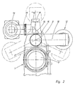
- the motion picture camera has a housing 1, on the front side 2 of which a taking lens 3 is arranged.
- the film recording beam path passing through the taking lens 3 is periodically interrupted by a rotating mirror diaphragm, which deflects a viewfinder beam path 4 upward out of this film recording beam path 18.
- This viewfinder beam path 4 is displaced to the front 2 of the motion picture camera by means of a rhomboid prism 17 and strikes a partially reflecting or partially transparent beam splitter 5.
- a beam component 6 is reflected by this beam splitter 5 to a viewfinder exit 7, which is arranged in the front side 2 of the camera housing 1.
- a magnifying arm 10 articulated at 9 is pivotably mounted in the region of more than 200 ° about the central axis 8, as shown in FIG.
- an eyepiece holder 11 is rotatably mounted, to which the eyepiece 12 of the viewfinder magnifier is attached.
- this construction enables a left-hand view and, due to the dash-dotted pivotability of the eyepiece view 12, enables the right and left-eyed viewing of the image generated by the taking lens 3.
- the eyepiece 12 can be used for a right-hand view, with a left- and right-eyed one also on the right side Insight into the eyepiece is possible.
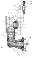
- a handle base 15 of the camera handle is formed in the top of the camera housing 1 on the front side 2, and a handle 14 of the camera handle is rotatably mounted in this handle base 15.
- the video beam path 13 is guided upwards by the beam splitter 5 through the handle base 15 of the camera handle and fed from a reflection prism 19 in the handle base 15 to a video adapter 16 which is mounted on the camera handle.
- the video beam path 13 is deflected by a prism 20, so that the video beam path 13 emerges from the video adapter 16 parallel to the taking lens 3.
- a video camera is connected to the video adapter 16 in a manner known per se, which is connected to a monitor, for example via a video cable, and thus permits the assistant to view the recorded image separately.
- the viewfinder beam path is guided such that image viewing on both sides and left-eyed and right-eyed is possible, the video beam path emerging at the front end of the camera in such a way that the camera can be carried by means of a handle on the camera handle , which can have a corresponding length.
- the handle 14 of the camera handle which is sufficient for easy handling because of its pivotability Can have length without hindering a cassette change, is rotatably mounted on a handle base 15 of the camera handle and combined with the video output, so that both parts can be pivoted to insert a slide-in cassette.
Abstract
Description
- Die Erfindung bezieht sich auf eine Laufbild-Filmaufnahmekamera nach dem Oberbegriff des Anspruchs 1.
- Aus der DE-C-36 15 424 ist eine Laufbild-Filmlaufnahmekamera mit einem Filmaufnahme-Strahlengang bekannt, aus dem mittels eines periodisch unterbrechenden Spiegels zeitweise ein Sucherstrahlengang abgezweigt wird. Aus diesem Sucherstrahlengang wird durch einen Strahlenteiler ein Videortrahlengang zu einer Videoaufnahmekamera abgezweigt, so daß gleichzeitig Film- und Fernsehaufnahmen gemacht werden können.
- Diese bekannte Kamera weist einen sperrigen Aufbau auf, da die Sucherlupe starr oberhalb des Kameragehäuses parallel zum Objektiv angeordnet ist und die Videoaufnahmekamera senkrecht zur Objektivachse. Ein kompakter Kameraaufbau mit Handgriff und ansetzbaren Filmkassetten ist bei einer derartigen Anordnung nicht möglich.
- In der DE 22 00 690 C3 ist eine Laufbild-Siegelreflexkamera mit Betrachtungslupe beschrieben, bei welcher der von der Spiegelreflexeinrichtung aus dem Aufnahmestrahlengang abgespaltene Sucherstrahlengang mittig oberhalb des Aufnahmeobjetivs aus dem Kameragehäuse austritt. Um eine linksäugige und rechtsäugige Betrachtung zu ermöglichen, ist der Sucheraustritt aus dem Kameragehäuse an dessen Frontseite angeordnet und um die Mittelachse dieses Sucheraustrittes ist der mittels wenigstens eines angelenkten Lupenschenkels und eines Okularträgers nach hinten umgelenkte Okulareinblick der Betrachtungslupe zwischen der rechten und der linken Kameraseite verschwenkbar.
- Es besteht ein Bedarf an Laufbild-Filmaufnahmekameras, die kompakt aufgebaut und mit Schubkassetten ausgerüstet sind und trotz dieses kompakten Aufbaus vielseitig einsetzbar sind.
- Der Erfindung liegt die Aufgabe zugrunde eine kompakt aufgebaute, tragbare Laufbildkamera mit Einschubkassetten derart zu gestalten, daß sie auch bei Anordnung eines Videoausganges eine beidseitige Anordnung der Betrachtungseinrichtung zuläßt.
- Erfindungsgemäß wird diese Aufgabe durch die technische Lehre des Inhalts des Anspruchs 1 gelöst.
- Die erfindungsgemäße Lösung ermöglicht das Verschwenken der Betrachtungseinrichtung (Sucherlupe) einer Laufbildkamera zu beiden Seiten des Kameraobjektivs, so daß eine rechts- und linksseitige Betrachtung des Aufnahmeobjektes problemlos möglich ist auch wenn eine zusätzliche Videoeinrichtung vorgesehen wird.
- In vorteilhafter Weise ist im Sucherstrahlengang, der insbesondere von einer Spiegelreflexeinrichtung aus dem Filmaufnahme-Strahlengang abgezweigt ist, ein teildurchlässiger refektierender Strahlenteiler angeordnet, der eine Sucherstrahlkomponente in einen Sucheraustritt an der Frontseite des Kameragehäuses reflektiert. Um die Mittelachse dieses Sucheraustritts ist ein mittels eines angelenkten Lupenschenkels und eines an diesen angelenkten Okularträgers nach hinten umgelenkter Okulareinblick der Betrachtungslupe zwischen der rechten und linken Kameraseite verschwenkbar und der vom Strahlenteiler durchgelassene Videostrahlengang ist durch ein Drehlager eines Kameragriffes hindurch einem an diesem angeordneten Videoadapter zugeführt.
- In vorteilhafter Weise sind durch diesen konstruktiven Aufbau sowohl der Sucheraustritt als auch der Austritt des Videostrahlenganges am vorderen Ende der Kamera angeordnet und die Verbindung des Videoadapters mit dem Kameragriff und die schwenkbare Lagerung des Kameragriffes ermöglicht, daß durch Verschwenken des Handgriffes die Rückseite der Kamera für eine Einschubkassette leicht zugänglich ist und daß in der Betriebsstellung des Handgriffes eine ausreichende Griff länge zur Verfügung steht, um mittels des Handgriffes die Laufbild-Filmaufnahmekamera leicht und bequem zu transportieren.
- Darüber hinaus ermöglicht die Verschwenkung des Okulareinblickes von der linken Kameraseite zur rechten einen beidseitigen Einblick und ferner bei verschiedenen Kameraeinsätzen Mittelstellungen des Okulareinblickes. Dieser Okulareinblick kann wegen der Anordnung des Videodapters an diesem in verschwenkter Lage vorbeigeführt und danach in Betrieb genommen werden.
- Besonders raumsparend ist es, daß in der Betriebsstellung des Kameragriffs der Videostrahlengang parallel zum Objektiv aus dem Videoadapter austritt.
- Um den Austritt des Videostrahlenganges aus der Kamera so weit wie möglich nach vorn zu verlegen, so daß trotz der Einschubkassette eine ausreichende Handgrifflänge zur Verfügung steht, ist zwischen dem von der Reflexeinrichtung aus dem Filmaufnahmestrahlengang abgelenkten Sucherstrahlengang und dem Strahlenteiler eine diesen Sucherstrahlengang zur Frontseite des Kameragehäuses hin versetzende optische Doppelspiegeleinrichtung, insbesondere eine Rhomboidprisma eingeschaltet.
- Durch diesen Aufbau wird der beispielsweise von einer verspiegelten Umlaufblende periodisch abgelenkte Sucherstrahlengang parallel zur Frontseite der Kamera hin versezt, um dort dem Strahlenteiler zugeführt zu werden. Dies ermöglicht, das Drehlager bzw. den Griffsockel für den Handgriff im Bereich der oberen Vorderkante der Filmkamera auszubilden.
- Ein Ausührungsbeispiel der Erfindung soll unter Bezugnahme auf die Figuren der Zeichnung beschrieben werden. Es zeigen:
- Figur 1
- eine schematische Längsschnittansicht eines Teiles der Laufbild-Filmkamera,
- Figur 2
- eine schematische Vorderansicht eines Teiles der Laufbildkamera,
- Figur 3
- eine teilweise geschnittene Draufsicht auf einen vorderen Abschnitt der Laufbildkamera.
- Gemäß Figur 1 weist die Laufbildkamera ein Gehäuse 1 auf, an dessen Frontseite 2 ein Aufnahmeobjektiv 3 angeordnet ist. Der das Aufnahmeobjektiv 3 durchsetzende Filmaufnahme-Strahlengang wird periodisch von einer rotierenden Spiegelblende unterbrochen, die einen Sucherstrahlengang 4 aus diesem Filmaufnahme-Strahlengang 18 nach oben ablenkt.
- Dieser Sucherstrahlengang 4 wird mittels eines Rhomboidprismas 17 zur Frontseite 2 der Laufbildkamera versetzt und trifft auf einen teilreflektierenden bzw. teildurchlässigen Strahlenteiler 5.
- Von diesem Strahlenteiler 5 wird eine Strahlenkomponente 6 zu einem Sucheraustritt 7 reflektiert, der in der Frontseite 2 des Kameragehäuses 1 angeordnet ist. Gemäß Figur 3 ist um die Mittelachse 8 ein bei 9 angelenkter Lupenschenkel 10 in einem Bereich von über 200° verschwenkbar gelagert, wie Figur 2 mit der strichpunktierten Darstellung verschiedener Stellungen des Lupenschenkels 10 verdeutlicht. Am Ende des Lupenschenkels 10 ist ein Okularträger 11 drehbar gelagert, an dem der Okulareinblick 12 der Sucherlupe befestigt ist.
- Wie Figur 3 zeigt, wird durch diesen Aufbau ein linksseitiger Einblick und infolge der strichpunktiert dargestellten Schwenkbarkeit des Okulareinblicks 12 eine rechts- und linksäugige Betrachtung des vom Aufnahmeobjektiv 3 erzeugten Bildes ermöglicht. Durch eine Verschwenkung um die Mittelachse 8 kann der Okulareinblick 12 für einen rechtsseitigen Einblick verwendet werden, wobei auch auf der rechten Seite ein links- und rechtsäugiger Einblick in den Okulareinblick möglich ist.
- Der vom Strahlenteiler 5 durchgelassene Anteil des Sucherstrahlengangs 4 bildet einen Videostrahlengang 13, der in Figur 1 schematisch dargestellt ist. In der Oberseite des Kameragehäuses 1 ist an der Frontseite 2 ein Griffsockel 15 des Kameragriffes ausgebildet und in diesem Griffsockel 15 ist ein Handgriff 14 des Kameragriffes drehbar gelagert.
- Wie die Figuren 2 und 3 schematisch zeigen, wird der Videostrahlengang 13 vom Strahlenteiler 5 nach oben durch den Griffsockel 15 des Kameragriffes hindurchgeführt und von einem Reflektionsprisma 19 im Griffsockel 15 einem Videoadapter 16 zugeleitet, der am Kameragriff montiert ist. Im Videoadapter 16 wird der Videostrahlengang 13 durch ein Prisma 20 umgelenkt, so daß der Videostrahlengang 13 parallel zum Aufnahmeobjektiv 3 aus dem Videoadapter 16 austritt. Am Videoadapter 16 wird in an sich bekannter Weise eine Videokamera angeschlossen, die beispielsweise über ein Videokabel mit einem Monitor verbunden wird und somit die getrennte Betrachtung des Aufnahmebildes durch einen Assistenten zuläßt.
- Durch die erfindungsgemäße Merkmalskombination wird wie dargestellt der Sucherstrahlengang so geleitet, daß eine beidseitige und auf beiden Seiten eine linksäugige und eine rechtsäugige Bildbetrachtung möglich ist, wobei der Videostrahlengang am vorderen Ende der Kamera derart austreten kann, daß die Kamera mittels eines Handgriffes des Kameragriffes tragbar ist, der eine entsprechende Länge aufweisen kann.
- Der Handgriff 14 des Kameragriffes, der wegen seiner Schwenkbarkeit eine zur einfachen Handhabbarkeit hinreichende Länge aufweisen kann, ohne einen Kassettenwechsel zu behindern, ist drehbar auf einem Griffsockel 15 des Kameragriffes gelagert und mit dem Videoausgang kombiniert, so daß beide Teile zum Einsetzen einer Einschubkassette verschwenkt werden können.
Claims (3)
- Laufbild-Filmaufnahmekamera miteinem Kameragehäuse (1) mit einem Filmaufnahme-Strahlengang (18), an dessen Frontseite (2) ein Aufnahmeobjektiv. (3) angeordnet ist,einem aus dem Filmaufnahme-Strahlengang (18) mittels einer Spiegelreflexeinrichtung abgelenkten Sucherstrahlengang (4),einer im Sucherstrahlengang (4) angeordneten reflektierenden Einrichtung (5), die den Sucherstrahlengang derart umlenkt, daß eine Sucherstrahlenkomponente (6) in einen Sucheraustritt (7) an der Frontseite (2) des Kameragehäuses (1) reflektiert wird,einem an den Sucheraustritt (7) angelenkten Lupenschenkel (10),einem an den Lupenschenkel (10) angelenkten Okularträger (11), mit dem ein zur Rückseite des Kameragehäuses (1) umgelenkter Okulareinblick (12) einer Betrachtungslupe verbunden ist, der um die Mittelachse (8) des Sucheraustritts (7) zwischen der rechten und der linken Seite des Kameragehäuses (1) verschwenkbar ist,dadurch gekennzeichnet, daß die den Sucherstrahlengang umlenkende reflektierende Einrichtung (5) als teildurchlässiger Strahlenteiler ausgebildet ist, um einen Videostrahlengang (13) vom Sucherstrahlengang (4) abzuzweigen und
daß in der Oberseite des Kameragehäuses (1) an der Frontseite (2) ein Griffsockel (15) eines darin drehbar gelagerten Kamerahandgriffs (14) angeordnet ist, wobei am Griffsockel (15) ein Videoadapter (16) vorgesehen ist, dem der von dem Strahlenteiler (5) durchgelassene Videostrahlengang (13) durch den Griffsockel (15) zugeführt ist. - Laufbild-Filmaufnahmekamera nach Anspruch 1, dadurch gekennzeichnet, daß in der Betriebsstellung des Kamera-Handgriffs (14) der Videostrahlengang (13) parallel zum Objektiv (3) aus dem Videoadapter (16) austritt.
- Laufbild-Filmaufnahmekamera nach Anspruch 1 oder 2, dadurch gekennzeichnet, daß zwischen dem von der Spiegelreflexeinrichtung aus dem Filmaufnahme-Strahlengang (18) abgelenkten Sucherstrahlengang (4) und dem Strahlenteiler (5) eine den Sucherstrahlengang (4) zur Frontseite (2) des Kameragehäuses (1) hin versetzende optische Doppelspiegeleinrichtung (17), insbesondere ein Rhomboidprisma, eingeschaltet ist.
Priority Applications (1)
| Application Number | Priority Date | Filing Date | Title |
|---|---|---|---|
| AT92906662T ATE145994T1 (de) | 1992-03-10 | 1992-03-10 | Laufbild-filmaufnahmekamera |
Applications Claiming Priority (1)
| Application Number | Priority Date | Filing Date | Title |
|---|---|---|---|
| PCT/DE1992/000205 WO1993018433A1 (de) | 1992-03-10 | 1992-03-10 | Laufbild-filmaufnahmekamera |
Publications (2)
| Publication Number | Publication Date |
|---|---|
| EP0630489A1 EP0630489A1 (de) | 1994-12-28 |
| EP0630489B1 true EP0630489B1 (de) | 1996-12-04 |
Family
ID=37429247
Family Applications (1)
| Application Number | Title | Priority Date | Filing Date |
|---|---|---|---|
| EP92906662A Expired - Lifetime EP0630489B1 (de) | 1992-03-10 | 1992-03-10 | Laufbild-filmaufnahmekamera |
Country Status (4)
| Country | Link |
|---|---|
| US (1) | US5612755A (de) |
| EP (1) | EP0630489B1 (de) |
| DE (2) | DE4107577C1 (de) |
| WO (1) | WO1993018433A1 (de) |
Families Citing this family (4)
| Publication number | Priority date | Publication date | Assignee | Title |
|---|---|---|---|---|
| EP0830781A4 (de) * | 1995-03-24 | 1999-04-07 | Lightstorm Technologies Inc | Videosucher |
| EP1111443A1 (de) * | 1999-12-21 | 2001-06-27 | Peter Dipl.-Ing. Denz | Laufbildkamera mit einem durch ein Okular zu betrachtenden elekronischen Sucher |
| US20040212996A1 (en) * | 2003-05-02 | 2004-10-28 | Friedrich Burckhardt | Ring lamp |
| US10617305B2 (en) * | 2013-02-28 | 2020-04-14 | Canfield Scientific, Incorporated | Dermatoscope devices |
Family Cites Families (12)
| Publication number | Priority date | Publication date | Assignee | Title |
|---|---|---|---|---|
| US2698356A (en) * | 1951-10-17 | 1954-12-28 | Paul A Roos | Combined motion-picture and television camera |
| FR2029969A5 (de) * | 1969-03-20 | 1970-10-23 | Schaefer Albert | |
| DE2200690C3 (de) * | 1972-01-07 | 1975-09-11 | Arnold & Richter Kg, 8000 Muenchen | Laufbild-Spiegelreflexkamera |
| US3913116A (en) * | 1972-01-07 | 1975-10-14 | Arnold & Richter Kg | Camera with adjustable viewfinder |
| GB2076177B (en) * | 1980-04-18 | 1983-10-12 | Samuelson Film Service Ltd | Auxiliary viewfinder system for motion picture cameras |
| EP0162311A3 (de) * | 1984-04-25 | 1987-08-19 | Arnold & Richter Cine Technik Gmbh & Co. Betriebs Kg | Steuerschaltung für eine Videokamera und Verfahren zum Steuern einer Videokamera |
| US4591254A (en) * | 1984-10-26 | 1986-05-27 | Bronislaw Sokolowski | Adaptor for T.V. camera |
| DE3615424A1 (de) * | 1986-05-07 | 1987-11-12 | Arnold & Richter Kg | Laufbild-filmaufnahmekamera |
| US4705374A (en) * | 1986-09-11 | 1987-11-10 | Clairmont Camera, Inc. | Tilting viewfinder and video door accessory for motion-picture camera |
| US5166718A (en) * | 1987-10-30 | 1992-11-24 | Canon Kabushiki Kaisha | Finder optical system |
| US5034822A (en) * | 1989-09-13 | 1991-07-23 | Stevens William M | Video camera adaptor for film cameras |
| DE9013698U1 (de) * | 1990-10-01 | 1990-12-06 | Denz, Peter, 8000 Muenchen, De |
-
1991
- 1991-03-07 DE DE4107577A patent/DE4107577C1/de not_active Expired - Lifetime
-
1992
- 1992-03-10 WO PCT/DE1992/000205 patent/WO1993018433A1/de active IP Right Grant
- 1992-03-10 DE DE59207636T patent/DE59207636D1/de not_active Expired - Lifetime
- 1992-03-10 EP EP92906662A patent/EP0630489B1/de not_active Expired - Lifetime
- 1992-03-10 US US08/295,890 patent/US5612755A/en not_active Expired - Lifetime
Non-Patent Citations (1)
| Title |
|---|
| Bedienungsanleitung ARRIFLEX 16 SR II, Arnold & Richter Cine Technik, München 1984, Seiten 27-29 und 49-51 * |
Also Published As
| Publication number | Publication date |
|---|---|
| DE4107577C1 (de) | 1992-09-03 |
| DE59207636D1 (de) | 1997-01-16 |
| WO1993018433A1 (de) | 1993-09-16 |
| EP0630489A1 (de) | 1994-12-28 |
| US5612755A (en) | 1997-03-18 |
Similar Documents
| Publication | Publication Date | Title |
|---|---|---|
| DE2418402C3 (de) | Endoskop mit veränderbarer Richtung des Blickfeldes | |
| DE19814731B4 (de) | Operationsmikroskop | |
| DE2415319B2 (de) | Kamera zur aufnahme des augenhintergrundes | |
| DE4013592C2 (de) | ||
| DE3529026A1 (de) | Optisches system fuer ein endoskop | |
| DE4212924A1 (de) | Stereomikroskop | |
| EP0523261A1 (de) | Diaprojektor zur Wand- und Mattscheibenprojektion | |
| DE3933190C2 (de) | ||
| DE2437498B1 (de) | Einäugige Spiegelreflex-Kassettenfilmkamera mit einem Varioobjektiv | |
| EP0085317A1 (de) | Universeller Binokulartubus für Mikroskope | |
| EP0630489B1 (de) | Laufbild-filmaufnahmekamera | |
| DE3211084C2 (de) | Optisches Mikroskop-System | |
| WO1991012550A1 (de) | Monokulares teleskop | |
| DE3715967C2 (de) | ||
| DE3525526C1 (en) | Motion-picture film camera with viewing magnifier extension | |
| DE2200690C3 (de) | Laufbild-Spiegelreflexkamera | |
| EP1237031A2 (de) | Optisches Instrument bzw. Gerät mit einem binokularen Einblick | |
| EP1533641B1 (de) | Trinokulartubus für Stereomikroskope | |
| WO1999066362A1 (de) | Optisches vorsatzsystem für eine kamera | |
| DE2806857C3 (de) | Fotografischer Apparat mit einem Aufnahmeobjektiv und einem Suchersystem | |
| DE4112755C2 (de) | Vorrichtung zum Betrachten von stereoskopischen Bildern | |
| DE4302173A1 (de) | Laufbild-Filmaufnahmekamera mit einer Einrichtung zur Abzweigung eines Videobildes | |
| DE102004010971A1 (de) | Optische Einrichtung für eine Kamera | |
| DE2144941A1 (de) | Vario-Objektiv | |
| DE864049C (de) | Spiegelreflex-Kleinbild-Kamera |
Legal Events
| Date | Code | Title | Description |
|---|---|---|---|
| PUAI | Public reference made under article 153(3) epc to a published international application that has entered the european phase |
Free format text: ORIGINAL CODE: 0009012 |
|
| 17P | Request for examination filed |
Effective date: 19940915 |
|
| AK | Designated contracting states |
Kind code of ref document: A1 Designated state(s): AT CH DE FR GB IT LI |
|
| GRAG | Despatch of communication of intention to grant |
Free format text: ORIGINAL CODE: EPIDOS AGRA |
|
| 17Q | First examination report despatched |
Effective date: 19960216 |
|
| GRAH | Despatch of communication of intention to grant a patent |
Free format text: ORIGINAL CODE: EPIDOS IGRA |
|
| GRAH | Despatch of communication of intention to grant a patent |
Free format text: ORIGINAL CODE: EPIDOS IGRA |
|
| GRAA | (expected) grant |
Free format text: ORIGINAL CODE: 0009210 |
|
| AK | Designated contracting states |
Kind code of ref document: B1 Designated state(s): AT CH DE FR GB IT LI |
|
| REF | Corresponds to: |
Ref document number: 145994 Country of ref document: AT Date of ref document: 19961215 Kind code of ref document: T |
|
| REF | Corresponds to: |
Ref document number: 59207636 Country of ref document: DE Date of ref document: 19970116 |
|
| ITF | It: translation for a ep patent filed |
Owner name: PT & C. CONSULTING S.R.L. |
|
| REG | Reference to a national code |
Ref country code: CH Ref legal event code: NV Representative=s name: KURT ALLGEIER PATENTANWALTSBUERO |
|
| ET | Fr: translation filed | ||
| GBT | Gb: translation of ep patent filed (gb section 77(6)(a)/1977) |
Effective date: 19970304 |
|
| ET | Fr: translation filed |
Free format text: CORRECTIONS |
|
| PLBE | No opposition filed within time limit |
Free format text: ORIGINAL CODE: 0009261 |
|
| STAA | Information on the status of an ep patent application or granted ep patent |
Free format text: STATUS: NO OPPOSITION FILED WITHIN TIME LIMIT |
|
| 26N | No opposition filed | ||
| PGFP | Annual fee paid to national office [announced via postgrant information from national office to epo] |
Ref country code: CH Payment date: 20000327 Year of fee payment: 9 |
|
| PG25 | Lapsed in a contracting state [announced via postgrant information from national office to epo] |
Ref country code: LI Free format text: LAPSE BECAUSE OF NON-PAYMENT OF DUE FEES Effective date: 20010331 Ref country code: CH Free format text: LAPSE BECAUSE OF NON-PAYMENT OF DUE FEES Effective date: 20010331 |
|
| REG | Reference to a national code |
Ref country code: CH Ref legal event code: PL |
|
| REG | Reference to a national code |
Ref country code: GB Ref legal event code: IF02 |
|
| PGFP | Annual fee paid to national office [announced via postgrant information from national office to epo] |
Ref country code: FR Payment date: 20020318 Year of fee payment: 11 |
|
| PGFP | Annual fee paid to national office [announced via postgrant information from national office to epo] |
Ref country code: AT Payment date: 20020322 Year of fee payment: 11 |
|
| PG25 | Lapsed in a contracting state [announced via postgrant information from national office to epo] |
Ref country code: AT Free format text: LAPSE BECAUSE OF NON-PAYMENT OF DUE FEES Effective date: 20030310 |
|
| PG25 | Lapsed in a contracting state [announced via postgrant information from national office to epo] |
Ref country code: FR Free format text: LAPSE BECAUSE OF NON-PAYMENT OF DUE FEES Effective date: 20031127 |
|
| REG | Reference to a national code |
Ref country code: FR Ref legal event code: ST |
|
| PG25 | Lapsed in a contracting state [announced via postgrant information from national office to epo] |
Ref country code: IT Free format text: LAPSE BECAUSE OF NON-PAYMENT OF DUE FEES;WARNING: LAPSES OF ITALIAN PATENTS WITH EFFECTIVE DATE BEFORE 2007 MAY HAVE OCCURRED AT ANY TIME BEFORE 2007. THE CORRECT EFFECTIVE DATE MAY BE DIFFERENT FROM THE ONE RECORDED. Effective date: 20050310 |
|
| PGFP | Annual fee paid to national office [announced via postgrant information from national office to epo] |
Ref country code: DE Payment date: 20110302 Year of fee payment: 20 Ref country code: GB Payment date: 20110324 Year of fee payment: 20 |
|
| REG | Reference to a national code |
Ref country code: DE Ref legal event code: R071 Ref document number: 59207636 Country of ref document: DE |
|
| REG | Reference to a national code |
Ref country code: DE Ref legal event code: R071 Ref document number: 59207636 Country of ref document: DE |
|
| REG | Reference to a national code |
Ref country code: GB Ref legal event code: PE20 Expiry date: 20120309 |
|
| PG25 | Lapsed in a contracting state [announced via postgrant information from national office to epo] |
Ref country code: DE Free format text: LAPSE BECAUSE OF EXPIRATION OF PROTECTION Effective date: 20120311 |
|
| PG25 | Lapsed in a contracting state [announced via postgrant information from national office to epo] |
Ref country code: GB Free format text: LAPSE BECAUSE OF EXPIRATION OF PROTECTION Effective date: 20120309 |