EP0554371B1 - Protective eyewear for use in sports and the like - Google Patents
Protective eyewear for use in sports and the like Download PDFInfo
- Publication number
- EP0554371B1 EP0554371B1 EP91920307A EP91920307A EP0554371B1 EP 0554371 B1 EP0554371 B1 EP 0554371B1 EP 91920307 A EP91920307 A EP 91920307A EP 91920307 A EP91920307 A EP 91920307A EP 0554371 B1 EP0554371 B1 EP 0554371B1
- Authority
- EP
- European Patent Office
- Prior art keywords
- lens
- protective eyewear
- frame
- eyewear device
- lens element
- Prior art date
- Legal status (The legal status is an assumption and is not a legal conclusion. Google has not performed a legal analysis and makes no representation as to the accuracy of the status listed.)
- Expired - Lifetime
Links
Images


Classifications
-
- G—PHYSICS
- G02—OPTICS
- G02C—SPECTACLES; SUNGLASSES OR GOGGLES INSOFAR AS THEY HAVE THE SAME FEATURES AS SPECTACLES; CONTACT LENSES
- G02C11/00—Non-optical adjuncts; Attachment thereof
- G02C11/08—Anti-misting means, e.g. ventilating, heating; Wipers
-
- A—HUMAN NECESSITIES
- A61—MEDICAL OR VETERINARY SCIENCE; HYGIENE
- A61F—FILTERS IMPLANTABLE INTO BLOOD VESSELS; PROSTHESES; DEVICES PROVIDING PATENCY TO, OR PREVENTING COLLAPSING OF, TUBULAR STRUCTURES OF THE BODY, e.g. STENTS; ORTHOPAEDIC, NURSING OR CONTRACEPTIVE DEVICES; FOMENTATION; TREATMENT OR PROTECTION OF EYES OR EARS; BANDAGES, DRESSINGS OR ABSORBENT PADS; FIRST-AID KITS
- A61F9/00—Methods or devices for treatment of the eyes; Devices for putting-in contact lenses; Devices to correct squinting; Apparatus to guide the blind; Protective devices for the eyes, carried on the body or in the hand
- A61F9/02—Goggles
- A61F9/026—Paddings; Cushions; Fittings to the face
-
- A—HUMAN NECESSITIES
- A61—MEDICAL OR VETERINARY SCIENCE; HYGIENE
- A61F—FILTERS IMPLANTABLE INTO BLOOD VESSELS; PROSTHESES; DEVICES PROVIDING PATENCY TO, OR PREVENTING COLLAPSING OF, TUBULAR STRUCTURES OF THE BODY, e.g. STENTS; ORTHOPAEDIC, NURSING OR CONTRACEPTIVE DEVICES; FOMENTATION; TREATMENT OR PROTECTION OF EYES OR EARS; BANDAGES, DRESSINGS OR ABSORBENT PADS; FIRST-AID KITS
- A61F9/00—Methods or devices for treatment of the eyes; Devices for putting-in contact lenses; Devices to correct squinting; Apparatus to guide the blind; Protective devices for the eyes, carried on the body or in the hand
- A61F9/02—Goggles
- A61F9/028—Ventilation means
-
- A—HUMAN NECESSITIES
- A63—SPORTS; GAMES; AMUSEMENTS
- A63B—APPARATUS FOR PHYSICAL TRAINING, GYMNASTICS, SWIMMING, CLIMBING, OR FENCING; BALL GAMES; TRAINING EQUIPMENT
- A63B33/00—Swimming equipment attachable to the head, e.g. swim caps or goggles
- A63B33/002—Swimming goggles
- A63B33/004—Swimming goggles comprising two separate lenses joined by a flexible bridge
-
- G—PHYSICS
- G02—OPTICS
- G02C—SPECTACLES; SUNGLASSES OR GOGGLES INSOFAR AS THEY HAVE THE SAME FEATURES AS SPECTACLES; CONTACT LENSES
- G02C11/00—Non-optical adjuncts; Attachment thereof
- G02C11/12—Side shields for protection of the eyes
-
- G—PHYSICS
- G02—OPTICS
- G02C—SPECTACLES; SUNGLASSES OR GOGGLES INSOFAR AS THEY HAVE THE SAME FEATURES AS SPECTACLES; CONTACT LENSES
- G02C5/00—Constructions of non-optical parts
- G02C5/14—Side-members
- G02C5/146—Side-members having special front end
-
- G—PHYSICS
- G02—OPTICS
- G02C—SPECTACLES; SUNGLASSES OR GOGGLES INSOFAR AS THEY HAVE THE SAME FEATURES AS SPECTACLES; CONTACT LENSES
- G02C5/00—Constructions of non-optical parts
- G02C5/14—Side-members
- G02C5/20—Side-members adjustable, e.g. telescopic
-
- G—PHYSICS
- G02—OPTICS
- G02C—SPECTACLES; SUNGLASSES OR GOGGLES INSOFAR AS THEY HAVE THE SAME FEATURES AS SPECTACLES; CONTACT LENSES
- G02C5/00—Constructions of non-optical parts
- G02C5/22—Hinges
- G02C5/2263—Composite hinges, e.g. for varying the inclination of the lenses
-
- G—PHYSICS
- G02—OPTICS
- G02C—SPECTACLES; SUNGLASSES OR GOGGLES INSOFAR AS THEY HAVE THE SAME FEATURES AS SPECTACLES; CONTACT LENSES
- G02C7/00—Optical parts
- G02C7/02—Lenses; Lens systems ; Methods of designing lenses
-
- G—PHYSICS
- G02—OPTICS
- G02C—SPECTACLES; SUNGLASSES OR GOGGLES INSOFAR AS THEY HAVE THE SAME FEATURES AS SPECTACLES; CONTACT LENSES
- G02C7/00—Optical parts
- G02C7/16—Shades; shields; Obturators, e.g. with pinhole, with slot
-
- G—PHYSICS
- G02—OPTICS
- G02C—SPECTACLES; SUNGLASSES OR GOGGLES INSOFAR AS THEY HAVE THE SAME FEATURES AS SPECTACLES; CONTACT LENSES
- G02C2200/00—Generic mechanical aspects applicable to one or more of the groups G02C1/00 - G02C5/00 and G02C9/00 - G02C13/00 and their subgroups
- G02C2200/08—Modular frames, easily exchangeable frame parts and lenses
Definitions
- This invention relates to protective eyewear for use in sports and the like.
- the eyeglasses are configured in a wrap around design.
- the eye support is contoured to snugly fit the eye orbital and diverge therefrom outward to the lens support area of the frame to provide for maximum peripheral vision of at least 140 degrees.
- This invention relates to protective eyewear for use in sports and the like.
- the device which is the subject of this application is adapted to provide the prophylactic eye protection of goggles while giving the appearance of light weight, streamlined eye glasses with an unobstructed field of vision.
- Sunglasses were light weight, compact, stylish, easily put on and taken off, and did not obstruct the wearer's field of vision. Sunglasses were attached along the temples, around the ears, and not around the back of the head. Such attachment necessarily required that the frame be at least semi-rigid.
- goggles are customarily held in place by an elastic or adjustable head band.
- Goggles use a strap around the wearer's head, as the frame is flexible; goggles do not support temple bars because of their non-rigid frame.
- the head band is positioned circumferentially around the back of the wearer's head.
- the head band is attached, at both ends, to the goggle mask which is bent around the wearer's face. In this manner, goggles provide a larger field of vision and a tight seal against the user" face thereby shielding the user's eyes from the elements.
- goggles form a shielding seal around the face
- goggles are not a preferred form of eyewear
- goggles are typically large, non-rigid, bulky, awkward, and uncomfortable to the wearer.
- These problems are substantially obviated by the present invention, which provides a spectacle like frame with all of the protective benefits of goggles, while not impinging on the wearer's field of vision.
- Other prior art devices are known from US-A-4 405 212 and FR-A-324 973.
- the present invention as defined in claim 1 overcomes all of the inherent deficiencies and limitations in the prior art devices.
- the present invention is light weight, aesthetically pleasing, comfortable, and can be used to protect the eyes in any type of weather. It gives the appearance of eyeglasses while offering substantially more eye protection, without diminution in the wearer's field of vision.
- the present invention provides a resilient semi-rigid or rigid frame having a sealing area around the eyes with a web which diverges outwardly toward the frame.
- the frame is curvedly contoured around the face of the user and in conjunction with the diverging web, provides maximum peripheral visibility.
- the diverging web of the frame, and/or the inside of the frame may be provided with a plurality of vent holes to promote the circulation of air and thereby inhibit misting of the inner surface of the lenses.
- a ram air intake can be provided in the front face of the frame and disposed in the nose bridge area.
- the ram air intake can be located elsewhere on the front of the frame, if desired.
- the various vent holes and air intakes may also be covered with a thin breathable cellular foam material to further shield the user from the elements.
- a lens, or pair of lenses is secured at the frame.
- the lens, or pair of lenses may be of a double-walled construction.
- Each double-walled construction, having two lenses may be either separated by an air space or abutted against one another. If an air space is provided, the two lenses may have a different base curve to provide an air space while having a common peripheral edge, or they may have the same radius of curvature with a peripheral seal or gasket between them.
- the lenses are a new style of double lens in which the forward lens is convex and the rear lens is concave (the words “convex” and “concave” are used here meaning curved in both the horizontal and vertical directions), and the two lenses are bonded together along a single peripheral edge.
- These lenses may be formed with zero power in which the forward and rearward lenses are each constant thickness and different spherical radii of curvature to permit their edges to converge for bonding.
- a prescription may be ground into either lens. Special coatings can be provided on the adjacent faces of the two lenses which are protected from oxidation or scratching.
- the present invention may be further provided with a cushion around the sealing area for increased sealing and protection.
- temple bars Fixed positioning of the sports eyeglasses is accomplished by temple bars.
- the angular disposition of the general plane in which the frame lies may be further adjusted by providing adjusting connections at the temples.
- Each connection can be accomplished by a pivotal rack and pawl connection between the temple bars and the frame.
- the frame includes a pair of temple bar stubs being attached to the frame at opposing ends.
- a pair of temple bars are pivotally attached to each temple bar stub using a unique pivot pin and hole engagement configuration.
- Each temple bar includes a receiving segment having a pivot pin, rack receiving recess and an earpiece receiving channel.
- the temple bars may also be provided with length adjustable earpiece. and mastoid hooks to further aid in fitting the sports eyeglasses to the head and face of the user.
- This invention is to provides protective eyewear for use in any type of weather.
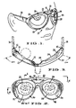
- Fig. 1 is a front elevation view of sports eyeglasses shown worn by a user.
- Fig. 2 is a front view of the sports eyeglasses of the present invention.
- Fig. 3 is a cross section of Fig. 2 showing one embodiment of attachment of temple bar for sports eyeglasses.
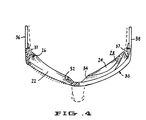
- Fig. 4 is a cross section of Fig. 2 showing another embodiment of attachment of temple bar for sports eyeglasses.
- Fig. 5 is a partial side view of the right side of sports eyeglasses.
- Fig. 6 is a cross section of the web taken along section 6-6 of Fig. 2, showing the position of the eye when worn by the wearer.
- Fig. 7 is a front view of sports eyeglasses, having orbital sealing gaskets, with the lenses removed.
- Fig. 8 is a cross section of the web taken along section 8-8 of Fig. 7, showing the position of the eye when worn by the wearer.
- Fig. 9 is a front elevation view of another embodiment of sports eyeglasses having a single lens.
- Fig. 10 is a front elevation view of another embodiment of sports eyeglasses.
- Fig. 11 is a left side view of the temple bar and frame orbital adjusting connection.
- Fig. 12 is a bottom view of the frame and frame orbital adjusting connection.
- Fig. 13 is a cross section taken along section line 13-13 of Fig. 10.
- Fig. 14 is an exploded side view of the left temple bar.
- Fig. 15 is partial cutaway assembled view of Fig. 14.
- Fig. 16 is an analogous view to that of Fig. 13 showing another embodiment of the sports eyeglasses having perspiration channel in the upper portion of the orbital sealing gasket.
- sports eyeglasses 20 are shown.
- sports eyeglasses 20 have a frame 21 which is attached to temple bars 36 and 38.
- Temple bars 36 and 38 are adapted to support the frame 21 on the wearer's head.
- the temple bars 36 and 38 are attached to the frame 21 with 90 degree angle hinge 35.
- the frame 21 is extended to accommodate attachment of the temple bars 36 and 38 with 180 degree angle hinge 37.
- Temple bars 36 and 38 may further be provided with mastoid hooks (not shown) which enhance the securing capability of the temple bars 36 and 38.
- the frame 21 is contoured in a wrap around configuration and has right lens opening 44 and left lens opening 45 in the lens support area 30. As shown in Figs. 1-16, the frame 21 has a pair of eye apertures 22 and 24 which are adapted to be aligned with the wearer's eyes. Lens support area 30 surrounds the eye apertures 22 and 24. Each eye aperture 22 and 24 is provided with a sealing area 26 and 28, respectively, which surrounds the eye aperture 22 or 24, and which snugly fits against the skin of the wearer adjacent to the eye. Referring to Figs. 3, 6 and 8, it is shown that the eye itself is forward of the sealing area 26 or 28 when the sports eyeglasses 20 are properly positioned on the face 23 of the wearer.
- Webs 32 and 34 diverge from each sealing area 26 and 28, respectively to the lens support area 30 for enclosure of each eye without obstructing peripheral vision. Webs 32 and 34 attach to the interior side 42 of frame 21 at its divergent side. As shown in Fig. 3, the wearer is able to see at least 140 degrees and preferably over 160 degrees of peripheral vision with both eyes as indicated by the peripheral vision angle 162 in Fig. 4.
- the webs 32 and 34 may be provided with vent holes 73 to promote air circulation.
- the vent holes may be continuous with air grooves situated on the inner aspect of the lens support area but not evident from the front view. Vent holes 73 may be covered with cellular foam material 29 to further shield the user.
- sports eyeglasses 20 are contoured to wrap around and closely fit the orbital area of the user which is the area barred by the user's nose, eyebrow and cheek bone.
- the exterior side 43 of sports eyeglasses 20 has a generally standard singles appearance, while the interior side 42, shown, for example, in Fig. 12, has more of a goggle-type appearance.
- the lens support area 30 supports at least one lens. Typically, two lenses 46 and 47 are housed by the lens support area 30 in the frame 21. However, as shown in Fig. 9, a continuous lens which covers both right lens opening 44 and left lens opening 45 may be used.
- the lenses ray be of single or double-walled construction, as illustrated in Fig. 13. In a double-walled construction, the lenses may have an airspace 76 and different radii of curvature. The double walled lenses may also have a single peripheral edge.
- ram air intake 51 for directing filtered air into the eye chamber through the vent holes.
- ram air intake 51 may be covered with ram air intake filter cover 52.
- Construction of ram air intake filter cover 52 typically can be from a thin breathable cellular foam material.
- ram air intake 51 can be circumferentially covered on the inner side so that the ram air intake 51 appears to be open when viewed from the exterior side 43 of the sports eyeglasses 20.
- intake air passing through is directed venturily down through those the vents 73 enclosed by the circumferential covering in the webs 32 and 34 to enhance ventilation and decrease the formation of mist on the lenses 46 and 47 of the sports eyeglasses 20.
- Figs. 10-16 show a further embodiment of the present invention.
- a pair of the temple bars 36 and 38 meet temple bar stubs, right temple bar stub 48 and left temple bar stub 49, which are attached and extend outward from opposite ends of the frame 21.
- Both temple bar stubs 48 and 49 have upper and lower pivot pin engagement holes 50 for engaging the temple bars 36 and 38.
- Only the left temple bar 38 is shown in its entirety.
- right temple bar 36 is identical in construction and is a mirror image of left temple bar stem 53.
- Left temple bar 38 has left rack arm 54 pivotally attached to left temple bar stub 49 via pivot pin 56 and lower pivot pin engagement hole 50.
- left rack segment 55 of left rack arm 54 is slidably received within left rack arm receiving recess 58 in left receiving segment 57.
- Left receiving segment 57 is also provided with a pivot pin 56 which pivotally engages the upper pivot pin engagement hole 50 in left temple bar stub 49.
- Left pawl arm 59 is attached within left rack arm receiving recess 58 and generally has a left resilient pawl member 61 attached at one end and includes a left pawl or protuberance 60 at its other end for engaging left rack segment 55.
- the opening in left rack arm receiving recess 58 is sized to closely receive left rack arm 55.
- Left resilient pawl member 61 bends downwardly to allow the adjustable movenent. The angle which frame 21 makes with respect to right and left temple bar 36 and 38, is dependent upon which particular tooth of rack segment 55 with which pawls 60 are engaged.
- left receiving segment 57 is also provided with left earpiece receiving channel 62 with slidably and frictionally engages channel member 64.
- Channel member 64 is colinearly attached to left earpiece 63, thereby providing a length adjustable earpiece 63 for sports eyeglasses 20.
- a right orbital adjusting connection is similarly constructed to the left orbital adjusting connection previously explained, and is shown best in Fig. 12.
- Figure 16 shows a second embodiment of sports eyeglasses 20 which includes a perspiration channel 80 in the upper portion of orbital sealing gasket 75.
- Orbital sealing gasket 75 may be added to sealing area 26 and 28 to enhance the seal and/or provide a facial cushion.
- the upper portion of orbital sealing gasket 75 is manufactured of a nonporous foam cushion material so as not to absorb perspiration.
- the orbital sealing gasket 75 could be manufactured from any suitable material and/or in a compressible accordion fashion to provide a tight seal against the face of the user.
- Perspiration channel 80 runs along the top of the of the frame 21 such that perspiration from the forehead of the user is directed to the lateral sides of sports eyeglasses 20, away from the face and eyes of the user.
- a further modification can include the insertion of grooves and/or a metal rod 49 at the interior of the frame 21 across the nose of the wearer for flexibility and fit.
Abstract
Description
- This invention relates to protective eyewear for use in sports and the like. The eyeglasses are configured in a wrap around design. The eye support is contoured to snugly fit the eye orbital and diverge therefrom outward to the lens support area of the frame to provide for maximum peripheral vision of at least 140 degrees.
- This invention relates to protective eyewear for use in sports and the like. The device which is the subject of this application is adapted to provide the prophylactic eye protection of goggles while giving the appearance of light weight, streamlined eye glasses with an unobstructed field of vision.
- Many diverse types of sports and other activities of necessity suggest that the participant wear some type of eye protection. Consequently, there are different types of eyeglasses and goggles which are appropriate for each activity. For example, in bad weather snow skiers want eye protection that prevents the penetration of wind, rain, snow, sleet, sand, dirt, dust and peripheral glare into the eyes. In fair weather, the desire for eye protection may be limited to protection against sun glare.
- For snow skiing, in the prior art, sunglasses sufficed as eye protection from the sun. Sunglasses were light weight, compact, stylish, easily put on and taken off, and did not obstruct the wearer's field of vision. Sunglasses were attached along the temples, around the ears, and not around the back of the head. Such attachment necessarily required that the frame be at least semi-rigid.
- In the prior art protective eyewear goggles were necessary for bad weather. Goggles, however, are large, cumbersome, awkward and difficult to wear. Most skiers, and other sports participants, find this objectionable. Preferable is the unrestraining fit and convenience offered by eye glasses which are lightly retained on the face of the user.
- Prior art devices such as those disclosed in U.S. Patent No. 1,669,229 Cook, U.S. Patent No. 1,677,747, U.S. Patent No. 1,936,746 Baker, U.S. Patent No. 1,754,694 Neuwirth unsuccessfully attempted to modify eyeglasses to provide all weather goggle-like eye protection while retaining the appearance and advantages of eyeglasses. These prior art devices were fitted with rubber, foam or some other non-rigid substance around the inside perimeter of the eyeglasses in an attempt to form an acceptable seal. However, as the non-rigid material easily deformed, it would not necessarily retain its resiliency and its shape after multiply uses, and would thereby become ineffective after a short period of time. Further, the placement of the non-rigid substance blocked peripheral vision, thereby severely restricting the wearer's field of vision.
- Moreover, unlike eyeglasses, goggles are customarily held in place by an elastic or adjustable head band. Goggles use a strap around the wearer's head, as the frame is flexible; goggles do not support temple bars because of their non-rigid frame.
- For goggles to create a protective seal, the head band is positioned circumferentially around the back of the wearer's head. The head band is attached, at both ends, to the goggle mask which is bent around the wearer's face. In this manner, goggles provide a larger field of vision and a tight seal against the user" face thereby shielding the user's eyes from the elements.
- Although goggles form a shielding seal around the face, goggles are not a preferred form of eyewear; goggles are typically large, non-rigid, bulky, awkward, and uncomfortable to the wearer. These problems are substantially obviated by the present invention, which provides a spectacle like frame with all of the protective benefits of goggles, while not impinging on the wearer's field of vision. Other prior art devices are known from US-A-4 405 212 and FR-A-324 973.
- The present invention as defined in claim 1 overcomes all of the inherent deficiencies and limitations in the prior art devices. The present invention is light weight, aesthetically pleasing, comfortable, and can be used to protect the eyes in any type of weather. It gives the appearance of eyeglasses while offering substantially more eye protection, without diminution in the wearer's field of vision.
- The present invention provides a resilient semi-rigid or rigid frame having a sealing area around the eyes with a web which diverges outwardly toward the frame. The frame is curvedly contoured around the face of the user and in conjunction with the diverging web, provides maximum peripheral visibility.
- The diverging web of the frame, and/or the inside of the frame, may be provided with a plurality of vent holes to promote the circulation of air and thereby inhibit misting of the inner surface of the lenses. Advantageously, a ram air intake can be provided in the front face of the frame and disposed in the nose bridge area. However, the ram air intake can be located elsewhere on the front of the frame, if desired. The various vent holes and air intakes may also be covered with a thin breathable cellular foam material to further shield the user from the elements.
- Accordingly, a lens, or pair of lenses, is secured at the frame. The lens, or pair of lenses, may be of a double-walled construction. Each double-walled construction, having two lenses, may be either separated by an air space or abutted against one another. If an air space is provided, the two lenses may have a different base curve to provide an air space while having a common peripheral edge, or they may have the same radius of curvature with a peripheral seal or gasket between them.
- Preferably, the lenses are a new style of double lens in which the forward lens is convex and the rear lens is concave (the words "convex" and "concave" are used here meaning curved in both the horizontal and vertical directions), and the two lenses are bonded together along a single peripheral edge. These lenses may be formed with zero power in which the forward and rearward lenses are each constant thickness and different spherical radii of curvature to permit their edges to converge for bonding. Alternatively, a prescription may be ground into either lens. Special coatings can be provided on the adjacent faces of the two lenses which are protected from oxidation or scratching.
- The present invention may be further provided with a cushion around the sealing area for increased sealing and protection.
- Fixed positioning of the sports eyeglasses is accomplished by temple bars. The angular disposition of the general plane in which the frame lies may be further adjusted by providing adjusting connections at the temples. Each connection can be accomplished by a pivotal rack and pawl connection between the temple bars and the frame.
- The frame includes a pair of temple bar stubs being attached to the frame at opposing ends. In one embodiment, a pair of temple bars are pivotally attached to each temple bar stub using a unique pivot pin and hole engagement configuration. Each temple bar includes a receiving segment having a pivot pin, rack receiving recess and an earpiece receiving channel. Thus, in this embodiment, the angle of the frame, with respect to the user" face, is dependant upon which particular tooth of the rack segment engages the pawl members.
- The temple bars may also be provided with length adjustable earpiece. and mastoid hooks to further aid in fitting the sports eyeglasses to the head and face of the user.
- This invention is to provides protective eyewear for use in any type of weather.
- Objects of the invention will become apparent upon reading the following specification and referring to the accompanying drawings.
- Fig. 1 is a front elevation view of sports eyeglasses shown worn by a user.
- Fig. 2 is a front view of the sports eyeglasses of the present invention.
- Fig. 3 is a cross section of Fig. 2 showing one embodiment of attachment of temple bar for sports eyeglasses.
- Fig. 4 is a cross section of Fig. 2 showing another embodiment of attachment of temple bar for sports eyeglasses.
- Fig. 5 is a partial side view of the right side of sports eyeglasses.
- Fig. 6 is a cross section of the web taken along section 6-6 of Fig. 2, showing the position of the eye when worn by the wearer.
- Fig. 7 is a front view of sports eyeglasses, having orbital sealing gaskets, with the lenses removed.
- Fig. 8 is a cross section of the web taken along section 8-8 of Fig. 7, showing the position of the eye when worn by the wearer.
- Fig. 9 is a front elevation view of another embodiment of sports eyeglasses having a single lens.
- Fig. 10 is a front elevation view of another embodiment of sports eyeglasses.
- Fig. 11 is a left side view of the temple bar and frame orbital adjusting connection.
- Fig. 12 is a bottom view of the frame and frame orbital adjusting connection.
- Fig. 13 is a cross section taken along section line 13-13 of Fig. 10.
- Fig. 14 is an exploded side view of the left temple bar.
- Fig. 15 is partial cutaway assembled view of Fig. 14.
- Fig. 16 is an analogous view to that of Fig. 13 showing another embodiment of the sports eyeglasses having perspiration channel in the upper portion of the orbital sealing gasket.
- Referring now to Figs. 1-16,
sports eyeglasses 20 are shown. Generally,sports eyeglasses 20 have aframe 21 which is attached to temple bars 36 and 38. Temple bars 36 and 38 are adapted to support theframe 21 on the wearer's head. In one embodiment, shown in Fig. 3, the temple bars 36 and 38 are attached to theframe 21 with 90degree angle hinge 35. In Fig. 4, another embodiment, theframe 21 is extended to accommodate attachment of the temple bars 36 and 38 with 180degree angle hinge 37. Temple bars 36 and 38 may further be provided with mastoid hooks (not shown) which enhance the securing capability of the temple bars 36 and 38. - The
frame 21 is contoured in a wrap around configuration and hasright lens opening 44 and leftlens opening 45 in thelens support area 30. As shown in Figs. 1-16, theframe 21 has a pair ofeye apertures Lens support area 30 surrounds theeye apertures eye aperture area eye aperture area sports eyeglasses 20 are properly positioned on the face 23 of the wearer. -
Webs area lens support area 30 for enclosure of each eye without obstructing peripheral vision.Webs interior side 42 offrame 21 at its divergent side. As shown in Fig. 3, the wearer is able to see at least 140 degrees and preferably over 160 degrees of peripheral vision with both eyes as indicated by theperipheral vision angle 162 in Fig. 4. Thewebs vent holes 73 to promote air circulation. The vent holes may be continuous with air grooves situated on the inner aspect of the lens support area but not evident from the front view. Vent holes 73 may be covered withcellular foam material 29 to further shield the user. - It can be seen that
sports eyeglasses 20 are contoured to wrap around and closely fit the orbital area of the user which is the area barred by the user's nose, eyebrow and cheek bone. Theexterior side 43 ofsports eyeglasses 20 has a generally standard singles appearance, while theinterior side 42, shown, for example, in Fig. 12, has more of a goggle-type appearance. - The
lens support area 30 supports at least one lens. Typically, twolenses lens support area 30 in theframe 21. However, as shown in Fig. 9, a continuous lens which covers bothright lens opening 44 and leftlens opening 45 may be used. The lenses ray be of single or double-walled construction, as illustrated in Fig. 13. In a double-walled construction, the lenses may have anairspace 76 and different radii of curvature. The double walled lenses may also have a single peripheral edge. - Between
right lens opening 44 and leftlens opening 45 there is positioned aram air intake 51 for directing filtered air into the eye chamber through the vent holes. Referring to Fig. 10,ram air intake 51 may be covered with ram airintake filter cover 52. Construction of ram airintake filter cover 52 typically can be from a thin breathable cellular foam material. - Alternatively,
ram air intake 51 can be circumferentially covered on the inner side so that theram air intake 51 appears to be open when viewed from theexterior side 43 of thesports eyeglasses 20. With the circumferential covering ofram air intake 51, intake air passing through is directed venturily down through those thevents 73 enclosed by the circumferential covering in thewebs lenses sports eyeglasses 20. - Figs. 10-16 show a further embodiment of the present invention. In the embodiment depicted in Figs. 10-16, a pair of the temple bars 36 and 38 meet temple bar stubs, right
temple bar stub 48 and lefttemple bar stub 49, which are attached and extend outward from opposite ends of theframe 21. Bothtemple bar stubs left temple bar 38 is shown in its entirety.
However, it should be apparent thatright temple bar 36 is identical in construction and is a mirror image of left temple bar stem 53.Left temple bar 38 has leftrack arm 54 pivotally attached to lefttemple bar stub 49 viapivot pin 56 and lower pivotpin engagement hole 50. Theleft rack segment 55 ofleft rack arm 54 is slidably received within left rackarm receiving recess 58 in left receivingsegment 57. Left receivingsegment 57 is also provided with apivot pin 56 which pivotally engages the upper pivotpin engagement hole 50 in lefttemple bar stub 49. -
Left pawl arm 59 is attached within left rackarm receiving recess 58 and generally has a leftresilient pawl member 61 attached at one end and includes a left pawl or protuberance 60 at its other end for engagingleft rack segment 55.
Advantageously, the opening in left rackarm receiving recess 58 is sized to closely receiveleft rack arm 55. Leftresilient pawl member 61 bends downwardly to allow the adjustable movenent. The angle whichframe 21 makes with respect to right and lefttemple bar rack segment 55 with which pawls 60 are engaged. - The back portion of left receiving
segment 57 is also provided with leftearpiece receiving channel 62 with slidably and frictionally engageschannel member 64.Channel member 64 is colinearly attached to leftearpiece 63, thereby providing a lengthadjustable earpiece 63 forsports eyeglasses 20. - Again, a right orbital adjusting connection is similarly constructed to the left orbital adjusting connection previously explained, and is shown best in Fig. 12.
- Figure 16 shows a second embodiment of
sports eyeglasses 20 which includes a perspiration channel 80 in the upper portion oforbital sealing gasket 75. Orbital sealinggasket 75 may be added to sealingarea orbital sealing gasket 75 is manufactured of a nonporous foam cushion material so as not to absorb perspiration. Theorbital sealing gasket 75 could be manufactured from any suitable material and/or in a compressible accordion fashion to provide a tight seal against the face of the user. - Perspiration channel 80 runs along the top of the of the
frame 21 such that perspiration from the forehead of the user is directed to the lateral sides ofsports eyeglasses 20, away from the face and eyes of the user. - Other modifications include addition of a nosepiece, enlarging the upper and/or lower portions of the lens frame and corresponding lenses to enhance superior and inferior vision. This is especially desirable in a sport such as bicycling where the user head is oftentimes face down, forcing the user to look out the top portion of the lens.
- Additionally, to frame 21 there may be added apertures to provide for increased venting through the interior of the
sports eyeglasses 20. A further modification can include the insertion of grooves and/or ametal rod 49 at the interior of theframe 21 across the nose of the wearer for flexibility and fit. - While there is shown and described the present preferred embodiment of the invention, it is to be distinctly understood that this invention is not limited thereto but may be variously embodied to practice within the scope of the following claims.
Claims (19)
- A protective eyewear frame (12) of a rigid or semi-rigid material comprising a pair of lens support areas (30) and comprising, web means depending from each lens support area to define a pair of eye apertures (22,24) and further to define a respective sealing area (26,28) surrounding each eye aperture, said pair of eye apertures (22,24) being adapted to be aligned with a user's eyes and said sealing area (26,28) being adapted to engage the user's skin adjacent to the eye characterised in that said lens support areas (30) surround each eye aperture (22,24) with the sealing areas (26,28) and lens support areas positioned to permit at least 140 degrees peripheral vision with both eyes, and said web (32,34) diverges from each sealing area (26,28) to the adjacent lens support area (30) in every direction to enclose the eye without obstructing the peripheral vision.
- A protective eyewear frame as claimed in claim 1 wherein said sealing area includes a sealing gasket (75) with a perspiration channel (80) disposed along its upper portion for directing perspiration away from the eyes and face of the user.
- A protective eyewear frame as claimed in claim 1 or claim 2 wherein said web includes ventilating apertures (73) therethrough.
- A protective eyewear device for use in sports and the like comprising a protective eyewear frame as claimed in any one of claims 1-3 further comprising curved lens means (46,47) covering the eye apertures (22,24) in the frame (21) at the lens support areas (30); and a pair of temple bar means (36,38) attached to the frame and adapted to support the frame on the wearer's head.
- A protective eyewear device according to claim 4, further comprising air grooves on the inner aspect of the lens support area (30) of the frame (21) continuous with the ventilating apertures (73).
- A protective eyewear device according to claim 4 or claim 5, further comprising a nosepiece, the nosepiece having a pair of nose pads adapted to conformedly contact the nose of the wearer.
- A protective eyewear device according to any of claims 4-6, further having a support means horizontally positioned at the top of the frame (21) bridging the region from one lens support area (30) to the other lens support area (30).
- A protective eyewear device according to any of claims 4-7, in which the ventilating apertures (73) are covered by permeable foam (29) for substantially reducing the passage of wind and foreign material through the said ventilating apertures.
- A protective eyewear device according to any of claims 4-8, further having a foam means contouring to partially cover the web (32,34) so that air is trapped and directed through the ventilation apertures (73) of the web to increase air circulation.
- A protective eyewear device according to any one of claims 4-9, wherein the temple bar means (36,38) are shaped to wrap around a user's mastoid region.
- A protective eyewear device according to any of claims 4-10 wherein the curved lens means comprises:-
a curved lens (46,47) mounted to each lens support area (30) to cover each aperture (22,24), each lens having a convex external surface and a concave internal surface and mounted in the frame (21) so that the convex external surface of each lens faces away from a wearer and the concave internal surface faces toward the wearer, each lens having a first lens element (47b) having said convex external surface and a concave rear surface, a second lens element (47a) having a convex front surface and said concave external surface, the first and second lens elements being aligned and bonded together along a single peripheral edge to fix the orientation of the lens elements (47a, 47b) relative to each other whereby the concave rear surface of the first lens element and the convex front surface of the second lens element are facing and at least a portion of the said concave rear surface of the said first lens element is spaced apart from the convex front surface of said second lens element to form an airspace (76) between the lens elements. - A protective eyewear device according to claim 11, wherein the first lens element (47b) and the second lens element (47a) have different radii of curvature.
- A protective eyewear device according to claim 11 or 12, wherein the first lens element and the second lens element are both constant thickness spherical lenses.
- A protective eyewear device according to any one of claims 11 to 13, further having a sealing gasket along the single peripheral edge.
- A protective eyewear device according to any one of claims 11 to 14, in which the airspace (76) between the first and second lens elements contains air.
- A protective eyewear device according to any one of claims 11 to 15, wherein the second lens element is manufactured from a hydrophobic or hydrophilic material.
- A protective eyewear device according to any one of claims 11 to 15, wherein at least one of the concave rear surface of the first lens element and the convex front surface of the second lens element is coated.
- A protective eyewear device according to claim 17, wherein the coating is antireflective.
- A protective eyewear device according to claim 17 or 18, wherein the coating is hydrophilic or hydrophobic.
Applications Claiming Priority (3)
| Application Number | Priority Date | Filing Date | Title |
|---|---|---|---|
| US07/601,467 US5191364A (en) | 1989-09-11 | 1990-10-23 | Protective eyewear for use in sports and the like |
| US601467 | 1990-10-23 | ||
| PCT/US1991/007761 WO1992007293A1 (en) | 1990-10-23 | 1991-10-21 | Protective eyewear for use in sports and the like |
Publications (3)
| Publication Number | Publication Date |
|---|---|
| EP0554371A1 EP0554371A1 (en) | 1993-08-11 |
| EP0554371A4 EP0554371A4 (en) | 1994-03-16 |
| EP0554371B1 true EP0554371B1 (en) | 1997-07-23 |
Family
ID=24407595
Family Applications (1)
| Application Number | Title | Priority Date | Filing Date |
|---|---|---|---|
| EP91920307A Expired - Lifetime EP0554371B1 (en) | 1990-10-23 | 1991-10-21 | Protective eyewear for use in sports and the like |
Country Status (7)
| Country | Link |
|---|---|
| US (2) | US5191364A (en) |
| EP (1) | EP0554371B1 (en) |
| JP (1) | JP3271973B2 (en) |
| AT (1) | ATE155899T1 (en) |
| AU (1) | AU648612B2 (en) |
| DE (1) | DE69126986T2 (en) |
| WO (1) | WO1992007293A1 (en) |
Families Citing this family (74)
| Publication number | Priority date | Publication date | Assignee | Title |
|---|---|---|---|---|
| US5191364A (en) * | 1989-09-11 | 1993-03-02 | Kopfer Rudolph J | Protective eyewear for use in sports and the like |
| US5387950B1 (en) * | 1990-08-09 | 1996-09-10 | Alfred Weltmann | Prescription eyewear made from non-prescription lens shield material |
| US5625425A (en) * | 1991-08-28 | 1997-04-29 | Kranhouse; Jon | Diving mask with lenses and method of fabricating the same |
| USRE37816E1 (en) | 1991-08-28 | 2002-08-13 | Jon Kranhouse | Diving mask with lenses and method of fabricating the same |
| US5331691A (en) * | 1992-11-02 | 1994-07-26 | John L. Runckel Trust | Intra-orbital swim goggles |
| US5339119A (en) * | 1993-12-17 | 1994-08-16 | Gardner Lawrence C | Eye protection device comprising a foam rubber-like resilient insert member |
| WO1996024315A1 (en) * | 1995-02-10 | 1996-08-15 | Kevin Francis Barr | Improvements to eyewear |
| US5805261A (en) * | 1995-04-04 | 1998-09-08 | Oakley, Inc. | Biased eyeglass frames |
| US5541674A (en) * | 1995-04-04 | 1996-07-30 | Oakley, Inc. | Dimensionally Stable eyewear |
| US6929364B1 (en) | 1995-04-04 | 2005-08-16 | Oakley, Inc. | Contoured metal eyeglass frames |
| US5708489A (en) * | 1995-04-04 | 1998-01-13 | Oakley, Inc. | Articulated eyeglass frame |
| US5648831A (en) * | 1995-06-07 | 1997-07-15 | Sentinel Importing Corporation | Asymmetrical eyewear |
| US5898468A (en) * | 1995-11-28 | 1999-04-27 | Spy Optic, Inc. | Fog-resistant sunglasses incorporating ventilation channels |
| US5610668A (en) * | 1995-11-28 | 1997-03-11 | Spy Optic, Inc. | Fog-resistant sunglasses incorporating ventilation channels |
| US6026518A (en) * | 1995-12-01 | 2000-02-22 | Brown; Robert L. | Forehead perspiration collection and transfer device in an eyeglass frame |
| US5638145A (en) * | 1996-02-29 | 1997-06-10 | Oakley, Inc. | Vented eyeglass lens |
| DE19612550C2 (en) * | 1996-03-29 | 1998-04-23 | Roland Koeller | Shooting glasses with multiple apertures |
| US6056399A (en) | 1997-01-29 | 2000-05-02 | Oakley, Inc. | Interchangeable nosepiece system |
| US6270467B1 (en) | 1998-04-14 | 2001-08-07 | Richard W. Yee | Apparatus, system, and method for preventing computer vision syndrome |
| US20040028852A1 (en) * | 2001-08-21 | 2004-02-12 | Weder Donald E. | Flexible, inflatable packaging materials and methods of making and using same |
| US6009564A (en) * | 1998-06-24 | 2000-01-04 | Oakley, Inc. | Optically corrected goggle |
| US6282727B1 (en) | 1999-07-13 | 2001-09-04 | Arthur Charles Lindahl | Sports eye wear with detachable goggle members |
| US6938277B2 (en) * | 1999-07-13 | 2005-09-06 | Arthur Charles Lindahl | Removable eyewear member |
| US6139144A (en) * | 1999-10-01 | 2000-10-31 | Hawaiko, Inc. | Cold weather eyeglass system with protective shield |
| USD428913S (en) * | 1999-11-24 | 2000-08-01 | Pan-Optx, Inc. | Sunglasses |
| US6233342B1 (en) | 2000-06-29 | 2001-05-15 | Pan-Optx, Inc. | Sunglasses with adjustable ventilation |
| US6312125B1 (en) * | 2000-08-03 | 2001-11-06 | Kevin D. Potts | Relaxation sunglasses having absorbent element for retaining aromatic fluids |
| US6902272B2 (en) | 2001-07-13 | 2005-06-07 | Laura F. Woford | Soft wrap frames with interchangeable lenses |
| US7091634B2 (en) * | 2001-07-26 | 2006-08-15 | Kbc America, Inc. | Half-jacket eyewear with removable dust shield |
| US6641263B2 (en) | 2001-08-14 | 2003-11-04 | Joel William Olney | Sunglasses with removable sealing member |
| US6550914B1 (en) | 2001-10-26 | 2003-04-22 | Pan-Optx, Inc. | Eyewear with filtered ventilation |
| CN100353210C (en) * | 2001-11-19 | 2007-12-05 | Kbc美洲有限公司 | Ventilated glasses with a removable pad |
| US6692124B2 (en) * | 2002-05-20 | 2004-02-17 | Robert Katz | Eyewear with ventilation |
| WO2004031839A2 (en) * | 2002-10-01 | 2004-04-15 | Pan-Optx, Inc. | Eyecup for glasses |
| JP2006507519A (en) * | 2002-10-07 | 2006-03-02 | エナジー・リレイテッド・デバイシズ・インコーポレーテッド | Electrostatic filtration eyewear |
| US20040111788A1 (en) * | 2002-12-12 | 2004-06-17 | Terry Chou | Composite len for swimming or diving goggles |
| KR20060008979A (en) * | 2003-06-03 | 2006-01-27 | 표한승 | Custom frame for eyeglass lenses and instruments |
| US7267434B2 (en) * | 2004-03-23 | 2007-09-11 | Dioptics Medical Products, Inc. | Eyeglasses and method of manufacture thereof |
| US7036927B2 (en) * | 2004-04-08 | 2006-05-02 | Kopfer Rudolph J | Face foam free protective eyewear with inner liner and vent |
| KR200367353Y1 (en) * | 2004-08-16 | 2004-11-10 | 최운택 | Glasses having multi-purpose |
| US7300151B2 (en) * | 2004-08-30 | 2007-11-27 | Seefit Incorporated | Apparatus and method for eye comfort |
| US20060272078A1 (en) * | 2004-10-29 | 2006-12-07 | Riccardo Polinelli | Apparatus and methodology to mitigate fogging on dual lens sports goggle |
| ITMI20042082A1 (en) * | 2004-10-29 | 2005-01-29 | Lem S R L | SCREEN FOR A MASK OF PROTECTION OF THE EYES AND METHOD OF REALIZING THE SAME |
| TWM278435U (en) * | 2005-03-02 | 2005-10-21 | Pi-Lin Jiang | Swimming goggles structure |
| US20060244897A1 (en) * | 2005-04-27 | 2006-11-02 | Guenther Siegmar W | Modular eyewear |
| EP3167854A1 (en) * | 2005-05-17 | 2017-05-17 | Revision Military, Inc. | Protective eyewear including auxiliary lenses |
| US7648234B2 (en) * | 2006-04-28 | 2010-01-19 | Kimberly-Clark Worldwide, Inc. | Eyewear with heating elements |
| US20070252943A1 (en) * | 2006-04-28 | 2007-11-01 | Welchel Debra N | Eyewear with enhanced air flow and/or absorption features |
| US20070252944A1 (en) * | 2006-04-28 | 2007-11-01 | Welchel Debra N | Eyewear with enhanced fit |
| US7488068B2 (en) * | 2006-04-28 | 2009-02-10 | Kimberly-Clark Worldwide, Inc. | Eyewear with mask attachment features |
| GB0609919D0 (en) | 2006-05-18 | 2006-06-28 | Speedo Int Ltd | Goggles |
| US7448750B2 (en) * | 2006-09-22 | 2008-11-11 | Oakley, Inc. | Quadrilateral lens |
| US20080189838A1 (en) * | 2007-02-12 | 2008-08-14 | Mage Jerome J M | Multi-base lens goggle |
| WO2009092043A1 (en) * | 2008-01-17 | 2009-07-23 | Eleanor Wink Jackson | All weather sport goggle |
| US20090271915A1 (en) * | 2008-04-30 | 2009-11-05 | Nicholas Ross | Dynamic Scenery Swim Mask |
| JP5088497B2 (en) * | 2008-05-30 | 2012-12-05 | 山本光学株式会社 | Exothermic synthetic resin lens and ophthalmic lens article |
| US20100290118A1 (en) * | 2008-12-25 | 2010-11-18 | Nobuaki Yamada | Liquid tank, viewing device for under-liquid observation, and optical film |
| US20100228689A1 (en) * | 2009-03-04 | 2010-09-09 | Robert Hall | Eyeglasses, eyecups, and methods of use and doing business |
| JP5480979B2 (en) * | 2010-01-08 | 2014-04-23 | スコット スポーツ エス エイ | Fit adjustment system for face |
| IT1401182B1 (en) * | 2010-07-27 | 2013-07-12 | Geox Spa | FRAME FOR GLASSES, MASKS FOR PROFESSIONAL OR SPORTS USE, AND SIMILAR |
| IT1401768B1 (en) * | 2010-07-28 | 2013-08-02 | Cersal S R L | SKI LENSES WITH DOUBLE LENSES |
| KR101108657B1 (en) * | 2011-08-30 | 2012-01-25 | (주)경도상사 | A industirial goggles |
| CN205007112U (en) | 2012-08-31 | 2016-02-03 | 奥克利有限公司 | Thing is worn to eyes and thing annex is worn to eyes with a plurality of ventilation states |
| WO2014138159A1 (en) | 2013-03-07 | 2014-09-12 | Oakley, Inc. | Regeneratable ant-fogging element for goggle |
| WO2014184765A1 (en) | 2013-05-15 | 2014-11-20 | Johan Verde | Spectacle frame with sun shielding |
| CA2943798C (en) | 2014-03-27 | 2019-08-20 | Oakley, Inc. | Mounting mechanism for eyewear |
| WO2016147131A1 (en) * | 2015-03-16 | 2016-09-22 | Martin Welt | Anti-glare eyewear |
| US10687981B2 (en) | 2015-10-09 | 2020-06-23 | Oakley, Inc. | Headworn supports with passive venting and removable lens |
| US9709817B2 (en) | 2015-12-07 | 2017-07-18 | Oakley, Inc. | Eyewear retention devices and methods |
| CN209433137U (en) | 2015-12-08 | 2019-09-24 | 奥克利有限公司 | Glasses traction device |
| US10359642B2 (en) | 2016-04-22 | 2019-07-23 | Oakley, Inc. | Mounting mechanism for eyewear |
| JP6744186B2 (en) * | 2016-09-30 | 2020-08-19 | 山本光学株式会社 | Protective glasses |
| US20220075198A1 (en) * | 2020-09-07 | 2022-03-10 | Htc Corporation | Glasses type display device and light-shielding face mask |
| KR102457910B1 (en) * | 2020-11-19 | 2022-10-24 | 김동건 | sunglasses for blind |
Family Cites Families (58)
| Publication number | Priority date | Publication date | Assignee | Title |
|---|---|---|---|---|
| FR321010A (en) * | 1902-05-09 | 1902-12-26 | Franck Valery Emile | Protective glasses for automobiles |
| FR324973A (en) * | 1902-10-04 | 1903-04-15 | Vinay Louis Auguste | New kind of safety glasses intended for industry and automobile drivers called "doctor's glasses l. A. Vinay" |
| US1031859A (en) * | 1907-10-21 | 1912-07-09 | Robert Malcom | Eye-shield. |
| US1168581A (en) * | 1915-01-11 | 1916-01-18 | F A Hardy & Company | Goggles or eye-protector. |
| GB127410A (en) * | 1918-05-30 | 1919-05-30 | Edward Thomas Parsons Goodyear | Improvements in and connected with Goggles. |
| US1478818A (en) * | 1922-02-13 | 1923-12-25 | Harvey S Cover | Eye goggles |
| US1433676A (en) * | 1922-02-13 | 1922-10-31 | Harvey S Cover | Eye goggles |
| US1562350A (en) * | 1922-07-15 | 1925-11-17 | George P Luckey | Nonfogging, nonfrosting double-lens goggles |
| US1677747A (en) * | 1924-11-01 | 1928-07-17 | E B Meyrowitz Inc | Goggles |
| US1669229A (en) * | 1926-11-05 | 1928-05-08 | E B Meyrowitz Inc | Goggle |
| US1741427A (en) * | 1927-03-10 | 1929-12-31 | E B Meyrowitz Inc | Goggles |
| US1936746A (en) * | 1927-10-18 | 1933-11-28 | American Optical Corp | Eye protector |
| US1720814A (en) * | 1928-02-21 | 1929-07-16 | American Optical Corp | Ophthalmic mounting |
| US1846679A (en) * | 1928-09-29 | 1932-02-23 | Fischer Charles | Goggles |
| US1853872A (en) * | 1928-11-10 | 1932-04-12 | E B Meyrowitz Inc | Goggles |
| US1754694A (en) * | 1929-06-28 | 1930-04-15 | Neuwirth Herman | Goggles |
| US2002543A (en) * | 1930-01-15 | 1935-05-28 | E B Meyrowitz Inc | Goggles |
| GB364970A (en) * | 1931-02-16 | 1932-01-14 | Leon Vienot | Improvements in and relating to protective goggles for the use of airmen, motorists and others |
| US2026435A (en) * | 1933-02-02 | 1935-12-31 | Ratti Giuseppe | Goggle |
| US1989876A (en) * | 1933-03-23 | 1935-02-05 | E B Meyrowitz Inc | Goggle |
| US2007186A (en) * | 1933-05-15 | 1935-07-09 | Walter G Farrell | Underwater eye protector |
| US2088262A (en) * | 1934-02-12 | 1937-07-27 | Corning Glass Works | Spectacles for under water use |
| FR827171A (en) * | 1937-09-28 | 1938-04-20 | Device for seeing under the water surface | |
| US2321159A (en) * | 1940-01-08 | 1943-06-08 | Donald T Ryan | Football goggles |
| US2364584A (en) * | 1941-11-22 | 1944-12-05 | Chicago Eye Shield Company | Goggle |
| US2387821A (en) * | 1942-12-14 | 1945-10-30 | American Optical Corp | Eye protection means |
| US2446048A (en) * | 1945-07-20 | 1948-07-27 | Donald E Kimball | Eyeshield |
| US2526181A (en) * | 1947-11-19 | 1950-10-17 | Wilen Charles Henry | Underwater goggles |
| US2608687A (en) * | 1948-01-02 | 1952-09-02 | American Optical Corp | Eye protection device |
| US2846684A (en) * | 1952-12-15 | 1958-08-12 | John D Hill | Removable lens goggles |
| US2865253A (en) * | 1956-12-10 | 1958-12-23 | Servo Corp Of America | Infrared achromat lens |
| US3040616A (en) * | 1958-12-26 | 1962-06-26 | American Optical Corp | Goggles and the like |
| US3377626A (en) * | 1966-04-01 | 1968-04-16 | Robert E. Smith | Insulated goggles |
| US3419909A (en) * | 1966-08-16 | 1969-01-07 | Ethel P. Spain | Eyeshield for use in hair-tinting and the like |
| ES133548Y (en) * | 1966-12-13 | 1968-07-01 | Optura, Dor, Gustav Gammert | ADJUSTABLE GLASSES TEMPLES. |
| US3591864A (en) * | 1969-05-27 | 1971-07-13 | Jon Ivor Allsop | Nonfog goggles |
| US3867175A (en) * | 1970-11-04 | 1975-02-18 | Esb Inc | Non-fogging material |
| FR2130907A5 (en) * | 1971-03-25 | 1972-11-10 | Bolle Maurice | |
| DE2161645A1 (en) * | 1971-12-11 | 1973-06-14 | Roehm Gmbh | DOG-PREVENTING COATING AGENT |
| US4099858A (en) * | 1976-07-01 | 1978-07-11 | Polaroid Corporation | Variable light transmission ophthalmic device |
| US4264987A (en) * | 1978-11-02 | 1981-05-05 | Runckel John L | Goggles |
| US4544245A (en) * | 1979-07-16 | 1985-10-01 | Mckesson Corporation | Adjustable safety spectacle |
| US4405212A (en) * | 1979-12-26 | 1983-09-20 | Cooper Leonard B | Spectacle frame and conversion accessories therefor |
| JPS6018967B2 (en) * | 1980-03-25 | 1985-05-14 | 山本防塵眼鏡株式曾社 | ski goggles |
| US4547049A (en) * | 1981-03-09 | 1985-10-15 | C & H Contact Lens Inc. | Composite ophthalmic lens system |
| US4741611A (en) * | 1981-03-26 | 1988-05-03 | Pro-Tec, Inc. | Eyeglasses adapted for sports and protective use |
| US4414693A (en) * | 1981-05-04 | 1983-11-15 | Brody Samuel S | Optical devices for use in moisture laden atmosphere |
| US4468819A (en) * | 1981-09-09 | 1984-09-04 | Kaisaku Ohno | Eye goggles having improved nose strap |
| US4707863A (en) * | 1983-01-24 | 1987-11-24 | Scott Usa Limited Partnership | Anti-fog goggle with foam frame |
| GB8504262D0 (en) * | 1985-02-19 | 1985-03-20 | Harris G W | Eye protectors |
| US4717249A (en) * | 1986-06-06 | 1988-01-05 | Fischer Bernard D | Diving mask with auxiliary lens |
| US4867553A (en) * | 1987-03-30 | 1989-09-19 | Frieder Philip M | Finished composite eyeglass lens |
| US4785481A (en) * | 1987-08-03 | 1988-11-22 | Palmer Iii Francis R | Eye protection device |
| US4792221A (en) * | 1988-01-25 | 1988-12-20 | John R. Gregory | Vertical plane adjusting mechanism for eyeglasses |
| US4877320A (en) * | 1988-10-03 | 1989-10-31 | Holden W Bruce | Eye-shielding glasses |
| US4955708A (en) * | 1989-04-20 | 1990-09-11 | Alan Kahaney | Sunglasses having adjustable temples |
| US5191364A (en) * | 1989-09-11 | 1993-03-02 | Kopfer Rudolph J | Protective eyewear for use in sports and the like |
| US5018223A (en) * | 1989-09-20 | 1991-05-28 | John R. Gregory | Non-fogging goggles |
-
1990
- 1990-10-23 US US07/601,467 patent/US5191364A/en not_active Expired - Lifetime
-
1991
- 1991-10-21 AT AT91920307T patent/ATE155899T1/en not_active IP Right Cessation
- 1991-10-21 JP JP51848491A patent/JP3271973B2/en not_active Expired - Fee Related
- 1991-10-21 DE DE69126986T patent/DE69126986T2/en not_active Expired - Fee Related
- 1991-10-21 EP EP91920307A patent/EP0554371B1/en not_active Expired - Lifetime
- 1991-10-21 WO PCT/US1991/007761 patent/WO1992007293A1/en active IP Right Grant
- 1991-10-21 AU AU89013/91A patent/AU648612B2/en not_active Ceased
-
1993
- 1993-01-08 US US08/002,469 patent/US5428411A/en not_active Expired - Lifetime
Also Published As
| Publication number | Publication date |
|---|---|
| JPH07508424A (en) | 1995-09-21 |
| DE69126986D1 (en) | 1997-08-28 |
| US5428411A (en) | 1995-06-27 |
| JP3271973B2 (en) | 2002-04-08 |
| EP0554371A4 (en) | 1994-03-16 |
| WO1992007293A1 (en) | 1992-04-30 |
| EP0554371A1 (en) | 1993-08-11 |
| US5191364A (en) | 1993-03-02 |
| AU8901391A (en) | 1992-05-20 |
| ATE155899T1 (en) | 1997-08-15 |
| DE69126986T2 (en) | 1997-11-27 |
| AU648612B2 (en) | 1994-04-28 |
Similar Documents
| Publication | Publication Date | Title |
|---|---|---|
| EP0554371B1 (en) | Protective eyewear for use in sports and the like | |
| US7278733B2 (en) | Sunglasses with removable sealing member | |
| US7182460B2 (en) | Radically shaped lenses and goggle assemblies and glasses employing same | |
| US6767095B1 (en) | Shielding member for eye protection against sun rays | |
| US5907868A (en) | Facial shield, particularly for protection from the sun | |
| US5133596A (en) | Eye and hearing protection | |
| AU749428B2 (en) | Ventilated browbar frame and eyewear | |
| US6666554B2 (en) | Protective eyewear kit | |
| US5956760A (en) | Facial sunshield with hinged visor/cap | |
| JP2000513458A (en) | Hinged eyeglass frames and eyeglasses | |
| US5841505A (en) | Sunglasses | |
| CA2010055A1 (en) | Holder for respirator | |
| US20060072065A1 (en) | Eyecup for glasses | |
| GB2384571A (en) | Sports spectacles |
Legal Events
| Date | Code | Title | Description |
|---|---|---|---|
| PUAI | Public reference made under article 153(3) epc to a published international application that has entered the european phase |
Free format text: ORIGINAL CODE: 0009012 |
|
| 17P | Request for examination filed |
Effective date: 19930427 |
|
| AK | Designated contracting states |
Kind code of ref document: A1 Designated state(s): AT BE CH DE DK ES FR GB GR IT LI LU NL SE |
|
| A4 | Supplementary search report drawn up and despatched |
Effective date: 19940126 |
|
| AK | Designated contracting states |
Kind code of ref document: A4 Designated state(s): AT BE CH DE DK ES FR GB GR IT LI LU NL SE |
|
| 17Q | First examination report despatched |
Effective date: 19951018 |
|
| GRAG | Despatch of communication of intention to grant |
Free format text: ORIGINAL CODE: EPIDOS AGRA |
|
| GRAH | Despatch of communication of intention to grant a patent |
Free format text: ORIGINAL CODE: EPIDOS IGRA |
|
| GRAH | Despatch of communication of intention to grant a patent |
Free format text: ORIGINAL CODE: EPIDOS IGRA |
|
| GRAA | (expected) grant |
Free format text: ORIGINAL CODE: 0009210 |
|
| AK | Designated contracting states |
Kind code of ref document: B1 Designated state(s): AT BE CH DE DK ES FR GB GR IT LI LU NL SE |
|
| PG25 | Lapsed in a contracting state [announced via postgrant information from national office to epo] |
Ref country code: BE Effective date: 19970723 Ref country code: LI Effective date: 19970723 Ref country code: AT Effective date: 19970723 Ref country code: DK Effective date: 19970723 Ref country code: CH Effective date: 19970723 Ref country code: GR Free format text: LAPSE BECAUSE OF FAILURE TO SUBMIT A TRANSLATION OF THE DESCRIPTION OR TO PAY THE FEE WITHIN THE PRESCRIBED TIME-LIMIT Effective date: 19970723 Ref country code: NL Free format text: LAPSE BECAUSE OF FAILURE TO SUBMIT A TRANSLATION OF THE DESCRIPTION OR TO PAY THE FEE WITHIN THE PRESCRIBED TIME-LIMIT Effective date: 19970723 Ref country code: ES Free format text: THE PATENT HAS BEEN ANNULLED BY A DECISION OF A NATIONAL AUTHORITY Effective date: 19970723 |
|
| REF | Corresponds to: |
Ref document number: 155899 Country of ref document: AT Date of ref document: 19970815 Kind code of ref document: T |
|
| REG | Reference to a national code |
Ref country code: CH Ref legal event code: EP |
|
| ET | Fr: translation filed | ||
| REF | Corresponds to: |
Ref document number: 69126986 Country of ref document: DE Date of ref document: 19970828 |
|
| ITF | It: translation for a ep patent filed |
Owner name: JACOBACCI & PERANI S.P.A. |
|
| PG25 | Lapsed in a contracting state [announced via postgrant information from national office to epo] |
Ref country code: GB Free format text: LAPSE BECAUSE OF NON-PAYMENT OF DUE FEES Effective date: 19971023 Ref country code: SE Effective date: 19971023 |
|
| PG25 | Lapsed in a contracting state [announced via postgrant information from national office to epo] |
Ref country code: LU Free format text: LAPSE BECAUSE OF NON-PAYMENT OF DUE FEES Effective date: 19971031 |
|
| NLV1 | Nl: lapsed or annulled due to failure to fulfill the requirements of art. 29p and 29m of the patents act | ||
| REG | Reference to a national code |
Ref country code: CH Ref legal event code: PL |
|
| PLBE | No opposition filed within time limit |
Free format text: ORIGINAL CODE: 0009261 |
|
| STAA | Information on the status of an ep patent application or granted ep patent |
Free format text: STATUS: NO OPPOSITION FILED WITHIN TIME LIMIT |
|
| GBPC | Gb: european patent ceased through non-payment of renewal fee |
Effective date: 19971023 |
|
| 26N | No opposition filed | ||
| REG | Reference to a national code |
Ref country code: FR Ref legal event code: TP |
|
| PGFP | Annual fee paid to national office [announced via postgrant information from national office to epo] |
Ref country code: DE Payment date: 20031023 Year of fee payment: 13 |
|
| PG25 | Lapsed in a contracting state [announced via postgrant information from national office to epo] |
Ref country code: DE Free format text: LAPSE BECAUSE OF NON-PAYMENT OF DUE FEES Effective date: 20050503 |
|
| PG25 | Lapsed in a contracting state [announced via postgrant information from national office to epo] |
Ref country code: IT Free format text: LAPSE BECAUSE OF NON-PAYMENT OF DUE FEES;WARNING: LAPSES OF ITALIAN PATENTS WITH EFFECTIVE DATE BEFORE 2007 MAY HAVE OCCURRED AT ANY TIME BEFORE 2007. THE CORRECT EFFECTIVE DATE MAY BE DIFFERENT FROM THE ONE RECORDED. Effective date: 20051021 |
|
| PGFP | Annual fee paid to national office [announced via postgrant information from national office to epo] |
Ref country code: FR Payment date: 20071009 Year of fee payment: 17 |
|
| REG | Reference to a national code |
Ref country code: FR Ref legal event code: ST Effective date: 20090630 |
|
| PG25 | Lapsed in a contracting state [announced via postgrant information from national office to epo] |
Ref country code: FR Free format text: LAPSE BECAUSE OF NON-PAYMENT OF DUE FEES Effective date: 20081031 |