EP0504518A1 - Helmet with visor - Google Patents
Helmet with visor Download PDFInfo
- Publication number
- EP0504518A1 EP0504518A1 EP91307631A EP91307631A EP0504518A1 EP 0504518 A1 EP0504518 A1 EP 0504518A1 EP 91307631 A EP91307631 A EP 91307631A EP 91307631 A EP91307631 A EP 91307631A EP 0504518 A1 EP0504518 A1 EP 0504518A1
- Authority
- EP
- European Patent Office
- Prior art keywords
- visor
- visor element
- primary
- helmet
- cap body
- Prior art date
- Legal status (The legal status is an assumption and is not a legal conclusion. Google has not performed a legal analysis and makes no representation as to the accuracy of the status listed.)
- Withdrawn
Links
- 230000002093 peripheral effect Effects 0.000 claims abstract description 13
- 238000007789 sealing Methods 0.000 claims abstract description 10
- 230000005494 condensation Effects 0.000 claims abstract description 6
- 238000009833 condensation Methods 0.000 claims abstract description 6
- 239000000853 adhesive Substances 0.000 claims abstract description 5
- 230000001070 adhesive effect Effects 0.000 claims abstract description 5
- 230000002401 inhibitory effect Effects 0.000 claims 2
- 230000000994 depressogenic effect Effects 0.000 abstract 1
- 238000004519 manufacturing process Methods 0.000 description 4
- 230000000717 retained effect Effects 0.000 description 2
- 125000006850 spacer group Chemical group 0.000 description 2
- 229920003002 synthetic resin Polymers 0.000 description 2
- 239000000057 synthetic resin Substances 0.000 description 2
- 239000004677 Nylon Substances 0.000 description 1
- 229930182556 Polyacetal Natural products 0.000 description 1
- NIXOWILDQLNWCW-UHFFFAOYSA-N acrylic acid group Chemical group C(C=C)(=O)O NIXOWILDQLNWCW-UHFFFAOYSA-N 0.000 description 1
- 229920000122 acrylonitrile butadiene styrene Polymers 0.000 description 1
- 230000008878 coupling Effects 0.000 description 1
- 238000010168 coupling process Methods 0.000 description 1
- 238000005859 coupling reaction Methods 0.000 description 1
- 230000000694 effects Effects 0.000 description 1
- 229920006248 expandable polystyrene Polymers 0.000 description 1
- 229920001778 nylon Polymers 0.000 description 1
- 239000004417 polycarbonate Substances 0.000 description 1
- 229920000515 polycarbonate Polymers 0.000 description 1
- 229920006324 polyoxymethylene Polymers 0.000 description 1
- 229920000915 polyvinyl chloride Polymers 0.000 description 1
- 239000004800 polyvinyl chloride Substances 0.000 description 1
- 229920005989 resin Polymers 0.000 description 1
- 239000011347 resin Substances 0.000 description 1
- 230000035939 shock Effects 0.000 description 1
- XLYOFNOQVPJJNP-UHFFFAOYSA-N water Substances O XLYOFNOQVPJJNP-UHFFFAOYSA-N 0.000 description 1
Images


Classifications
-
- A—HUMAN NECESSITIES
- A42—HEADWEAR
- A42B—HATS; HEAD COVERINGS
- A42B3/00—Helmets; Helmet covers ; Other protective head coverings
- A42B3/04—Parts, details or accessories of helmets
- A42B3/18—Face protection devices
- A42B3/22—Visors
- A42B3/24—Visors with means for avoiding fogging or misting
Definitions
- the present invention relates to helmets of a type having a visor and used primarily by a driver or a passenger of a snowmobile, a motorcycle or the like.
- a helmet comprising a cap body and a visor attached at left and right ends thereof to the cap body through a pivotal mountings means for opening and closing a window opening made in a front surface of the cap body
- the visor comprises: a primary visor element connected at left and right ends thereof to pivotal mounting means and having a recess in an inner surface, and an inner visor element fitted and coupled to a step which is formed at an entire peripheral edge of an opening of the recess and which forms part of the primary visor element, with a heat insulating space being defined in the recess by the primary visor element and the inner visor element, the primary visor element and the inner visor element having inner surfaces formed into a continuous surface coming into close contact with a sealing member provided on a peripheral edge of a window opening.
- both the visor elements can be correctly coupled to each other in a given relationship, so that the heat insulating space having a predetermined function is reliably defined between both the elements.
- the heat of the inner visor element can be retained by the heat insulating space and hence, condensation on the inner surface of the visor can be prevented regardless of conditions of use such as the presence and absence of an air flow incident on the helmet due to forward motion of the helmet through the air and the temperature of the outside air.
- the inner surfaces of the primary visor element and the inner visor element are formed into a continuous surface, the inner surface of the visor can be brought reliably into close contact with the sealing member at the peripheral edge of the window opening to tightly close the window opening, whenever the visor is fully closed. That is, even if a boundary line between the primary visor element and the inner visor element contacts the sealing member due to errors in fabrication and assembling of the pivotal mounting means, the function of the sealing member is maintained. Further, the primary visor element is connected to the pivotal mounting plate, so that not all the load applied to the visor is carried by the inner visor element. Therefore, it is possible to provide a reduction in wall thickness of the inner visor element and hence, a reduction in weight of the visor.
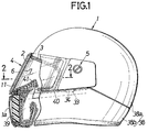
- Figure 1 shows a cap body 1 of a full-face type helmet having a chin-covering portion 1a immediately below a window opening 2 in a front surface thereof.
- a sealing member 3 made of rubber is fitted into and bonded to a peripheral edge of the window opening 2.
- a visor 4 is vertically movably mounted at its left and right opposite ends to the cap body 1 through a pivotal mounting means 5 to open and close the window opening 2.
- the visor 4 has an inner surface adapted to come into close contact with the sealing member 3 at a lowering limit to close the window opening 2, and is curved forwardly at a central portion to extend along a front profile of the cap body 1.
- the visor 4 is comprised of a thick primary visor element 6 and a thin inner visor element 7.
- a knob 6a projects from a lower end of the primary visor element 6.
- a recess 8 is provided in an inner surface of the primary visor element 6 at a location corresponding to the window opening 2, and moreover, a step 9 is formed at the entire peripheral edge of an opening of the recess 8 which is inset from the inner surface of the primary visor element 6.
- the step 9 has a depth equal to or slightly deeper than a thickness of the inner visor element 7.
- the entire peripheral edge of the inner visor element 7 overlies the step 9 and is bonded thereto with an adhesive 10 which remains flexible.
- a heat insulating space 11 enclosed by the recess 8 is defined by the inner visor element 7 and the primary visor element 6.
- a continuous surface 12 is formed on the inner surfaces of the primary visor element 6 and the inner visor element 7 and capable of reliably coming into close contact with the sealing member 3.
- Both the primary visor element 6 and the inner visor element 7 are formed of a synthetic resin having a high transparency and a low refractive index, e.g., polycarbonate, acrylic, or polyvinyl chloride resins.
- a transparent anti-misting or anti-fogging film 13 is formed on an inner surface of the recess 8 of the primary visor element 6 and inner and outer surfaces of the inner visor element 7.
- the pivotal mounting means 5 for connecting the left and right ends of the visor will be described below in connection with Figures 4 to 6.
- the left and right pivotal mounting means 5 have the same structure and hence, only the left pivotal mounting means 5 will be described.
- the pivotal mounting means 5 comprises a base plate 14 secured to a side of the cap body 1, an end plate 16 secured to an end of the primary visor element 6 by an eyelet 15, and a cover 17 covering the end plate 16 and supporting the end plate 16 for pivotal movement by cooperation with the base plate 14.
- Both the base plate 14 and the end plate 16 are formed from synthetic resin having high resistances to wear and shock, e.g. polyacetal, nylon or ABS.
- a pair of through-holes 18 and 19 are provided in the base plate 14 at a vertical distance therebetween, and nuts 20 and 21 are embedded in the cap body 1 in correspondence to the through-holes 18 and 19.
- the base plate 14 is secured to the cap body 1 by screwing machine screws 22 and 23 inserted through the through-holes 18 and 19 into the nuts 20 and 21.
- a cylindrical pivot 24 is projectingly provided on an outer side of the base plate 14 to concentrically surround the upper through-hole 18, and a pivot hole 25 is provided in the end plate 16, which pivot hole 25 is rotatably supported about the pivot 24.
- a stationary stopper 26 and a locating pin 27 are projectingly provided on the outer side of the base plate 14 at its upper and lower portions, respectively, and a movable stopper 28 is formed on the end plate 16 for defining the fully-open position of the visor 4 by cooperation with the stationary stopper 26.
- a cylindrical retainer 29 fitted over an outer periphery of a tip end of the pivot 24 to restrain the axial movement of the end plate 16, and a cylindrical spacer 30 abutting against the base plate 14 within the cylindrical retainer 29.
- the cylindrical spacer 30 is provided with a centrally disposed through-hole 31 coaxially aligned with the above-described through-hole 18.
- a cylindrical locating member 32 fitted over the locating pin 27, and a projection piece 34 engaged into an engage hole 33 in the outer side of the cap body 1.
- a click stop mechanism 35 is provided between the base plate 14 and the end plate 16 for retaining the visor 4 at its fully-closed position, a plurality of partially opening positions and its fully-opened position.
- the click stop mechanism 35 comprises several stationary click teeth 36, 36 --- projectingly provided on the outer side of the base plate 14 radially about the pivot 24, and a large number of movable click teeth 37, 37 --- projectingly provided on the inner side of the end plate 16 radially about the pivot hole 25.
- the click teeth 36, 36 --- and 37, 37--- are disengagably engaged with each other under the influence of resilient forces of the base plate 14 and the end plate 16.
- the cap body 1 is comprised of a shell 38 made of FRP and a shock-absorbing liner 39 made of foamed polystyrene and bonded to an inner surface of the shell 38.
- the shell 38 is divided at a location corresponding to the middle of the chin-covering portion 2a into an upper shell portion 38a and a lower shell portion 38b, which are superposed at their divided ends, with the lower shell portion 38b being outside, and are rivetted to each other.
- the engage hole 33 is defined between the upper and lower shell portions 38a and 38b by cutting-out of a portion of an inwardly bent collar 40 at an upper end of the lower shell portion 38b.
- a flexible expiration-air guide plate 41 is added to an upper edge of the chin-covering portion 1a of the cap body 1 to project inwardly of the cap body 1 and is adapted to deflect the expiration air from a user downwardly to prevent it from directly touching an inner surface of the visor 4.
- the helmet of the present invention When the helmet of the present invention is used with the visor 4 fully opened in cold districts or regions, even if the outer primary visor element 6 is cooled by the outside air, transfer or conduction of heat from the inner visor element 7 to the primary visor element 6 is inhibited by the heat insulating space 11 and the flexible adhesive 10, so that the inner visor element 7 can be maintained at a temperature substantially equal to that in the cap body 1, thereby preventing a clouding or fogging of the inner surface of the inner visor element 7 due to a large difference in temperature.
- the anti-misting film 13 is formed on the inner surface of the inner visor element 7, even if a portion of the expiration air from the user flows past the expiration-air guide plate 41 to touch the inner visor element 7, misting due to this can be prevented.
- the anti-misting film 13 is also formed on the inner surface of the primary visor element 6 and the outer surface of the inner visor element 7 which face to the heat insulating space 11, even if moisture should be contained in the air within the heat insulating space 11, misting due to such moisture can be likewise prevented.
- the inner visor element 7 is fitted into and coupled to the step 9 formed at the entire peripheral edge of the opening of the recess 8 in the primary visor element 6, the elements 6 and 7, even if they are curved as described above, can be coupled in an exact relative position to define the heat insulating space 11 with an even thickness at every locations in the recess 8 during fabrication of the visor 4. Therefore, the heat insulating function of the heat insulating space 11 can be stabilised even in mass production.
- the window opening 2 can be reliably and tightly closed. This ensures that errors in fabrication and assembling of the pivotal mounting means 5 or the like are substantially allowable.
- a wearer of the helmet grasps the knob 6a of the primary visor element 6 and moves it vertically. During this time, the end plate 16 coupled to the primary visor element 6 is pivotally moved about the pivot 24 of the base plate 14, while at the same time, the stationary and pivotable click teeth 36 and 37 of the click stop mechanism 35 slide over one another tooth by tooth in discrete steps.
- the knob 6a is released and the visor 4 is retained at the desired opened position by engagement of the click teeth 36 with the appropriate click teeth 37.
- the primary visor element 6 may be subjected to a slight strain during pivoting of the visor about the pivotal mounting means 5, but such strain is absorbed by the flexible adhesive 10 and is extremely rarely transmitted to the inner visor element 7, ensuring that the elements 6 and 7 do not peel-off from one another.
- the strain is rarely transmitted to the inner visor element 7, it is not necessary to ensure that the inner visor element 7 has a high strength, so that the inner visor element 7 may be made thinner than the primary visor element 6. This makes it possible to provide a reduction in weight of the visor 4 by reducing the wall thickness of the inner visor element 7.
Abstract
A recess (8) is provided in the inner surface of a primary visor element (6) which is connected to a cap body (1) of a helmet through a pivotal mounting means (5), and a step (9) depressed from the inner surface of the primary visor element (6) is formed at the entire peripheral edge of an opening of the recess (8). An inner visor element (7) is fitted to the step (9) and bonded thereto with a flexible adhesive, so that a heat insulating space (11) tightly closed in the recess (8) is defined by the primary visor element (6) and the inner visor element (7). The inner surfaces of the primary visor element (6) and the inner visor element (7) are formed into a continuous surface (12) which comes into close contact with a sealing member (3) provided at a peripheral edge of a window opening (2) in the cap body (1). This ensures that condensation on the inner surface of the visor (4) can be prevented regardless of conditions of use such as the presence and absence of an air flow over the helmet and the temperature of the air.
Description
- The present invention relates to helmets of a type having a visor and used primarily by a driver or a passenger of a snowmobile, a motorcycle or the like.
- It is already known that when a helmet having a visor is in use with the visor fully closed, part of the air stream incident on the helmet as the vehicle travels along is directed to an inner surface of the visor in order to prevent condensation on the inner surface of the visor which may occur due to expiration of air from a user (for example, see Japanese Patent Application Laid-open No. 159507/88).
- However, such a helmet suffers from the problem that when the vehicle is stationary, so that there is no longer an air flow incident on the visor, condensation is liable to form on the inner surface of the visor, and in use in a cold climate water vapour from the helmet wearer's breath may condense rapidly on the inner surface of the visor due to a large difference in temperature between the visor cooled by the outside air and the inside of the cap body. As a result, visibility through the visor may be significantly reduced.
- According to the present invention, there is provided a helmet comprising a cap body and a visor attached at left and right ends thereof to the cap body through a pivotal mountings means for opening and closing a window opening made in a front surface of the cap body, characterised in that the visor comprises:
a primary visor element connected at left and right ends thereof to pivotal mounting means and having a recess in an inner surface, and an inner visor element fitted and coupled to a step which is formed at an entire peripheral edge of an opening of the recess and which forms part of the primary visor element, with a heat insulating space being defined in the recess by the primary visor element and the inner visor element, the primary visor element and the inner visor element having inner surfaces formed into a continuous surface coming into close contact with a sealing member provided on a peripheral edge of a window opening. - With the above feature of the present invention, by the fitting and coupling of the inner visor element to the step, both the visor elements can be correctly coupled to each other in a given relationship, so that the heat insulating space having a predetermined function is reliably defined between both the elements. Thus, the heat of the inner visor element can be retained by the heat insulating space and hence, condensation on the inner surface of the visor can be prevented regardless of conditions of use such as the presence and absence of an air flow incident on the helmet due to forward motion of the helmet through the air and the temperature of the outside air.
- In addition, since the inner surfaces of the primary visor element and the inner visor element are formed into a continuous surface, the inner surface of the visor can be brought reliably into close contact with the sealing member at the peripheral edge of the window opening to tightly close the window opening, whenever the visor is fully closed. That is, even if a boundary line between the primary visor element and the inner visor element contacts the sealing member due to errors in fabrication and assembling of the pivotal mounting means, the function of the sealing member is maintained. Further, the primary visor element is connected to the pivotal mounting plate, so that not all the load applied to the visor is carried by the inner visor element. Therefore, it is possible to provide a reduction in wall thickness of the inner visor element and hence, a reduction in weight of the visor.
- For a better understanding of the present invention and to show how it may be carried into effect, reference will now be made, by way of example, to the accompanying drawings in which:
- Figure 1 is a partially sectioned side view of a helmet having a visor;
- Figure 2 is a sectional view taken along a line 2-2 in Figure 1;
- Figure 3 is an enlarged view of a portion of the helmet indicated by
arrow 3 in Figure 2; - Figure 4 is an enlarged side view of a pivotal mounting means shown in Figure 1;
- Figure 5 is a sectional view taken along a line 5-5 in Figure 4; and
- Figure 6 is an exploded perspective view of the pivotal mounting means.
- Referring to the drawings, Figure 1 shows a
cap body 1 of a full-face type helmet having a chin-covering portion 1a immediately below a window opening 2 in a front surface thereof. A sealingmember 3 made of rubber is fitted into and bonded to a peripheral edge of the window opening 2. Avisor 4 is vertically movably mounted at its left and right opposite ends to thecap body 1 through a pivotal mounting means 5 to open and close the window opening 2. Thevisor 4 has an inner surface adapted to come into close contact with the sealingmember 3 at a lowering limit to close thewindow opening 2, and is curved forwardly at a central portion to extend along a front profile of thecap body 1. - As shown in Figures 1 to 3 and 5, the
visor 4 is comprised of a thickprimary visor element 6 and a thininner visor element 7. Aknob 6a projects from a lower end of theprimary visor element 6. Arecess 8 is provided in an inner surface of theprimary visor element 6 at a location corresponding to thewindow opening 2, and moreover, astep 9 is formed at the entire peripheral edge of an opening of therecess 8 which is inset from the inner surface of theprimary visor element 6. Thestep 9 has a depth equal to or slightly deeper than a thickness of theinner visor element 7. The entire peripheral edge of theinner visor element 7 overlies thestep 9 and is bonded thereto with an adhesive 10 which remains flexible. Aheat insulating space 11 enclosed by therecess 8 is defined by theinner visor element 7 and theprimary visor element 6. At the same time, acontinuous surface 12 is formed on the inner surfaces of theprimary visor element 6 and theinner visor element 7 and capable of reliably coming into close contact with the sealingmember 3. - Both the
primary visor element 6 and theinner visor element 7 are formed of a synthetic resin having a high transparency and a low refractive index, e.g., polycarbonate, acrylic, or polyvinyl chloride resins. A transparent anti-misting or anti-fogging film 13 is formed on an inner surface of therecess 8 of theprimary visor element 6 and inner and outer surfaces of theinner visor element 7. - The pivotal mounting means 5 for connecting the left and right ends of the visor will be described below in connection with Figures 4 to 6. The left and right pivotal mounting means 5 have the same structure and hence, only the left pivotal mounting means 5 will be described.
- The pivotal mounting means 5 comprises a
base plate 14 secured to a side of thecap body 1, anend plate 16 secured to an end of theprimary visor element 6 by aneyelet 15, and acover 17 covering theend plate 16 and supporting theend plate 16 for pivotal movement by cooperation with thebase plate 14. Both thebase plate 14 and theend plate 16 are formed from synthetic resin having high resistances to wear and shock, e.g. polyacetal, nylon or ABS. - A pair of through-
holes base plate 14 at a vertical distance therebetween, andnuts cap body 1 in correspondence to the through-holes base plate 14 is secured to thecap body 1 byscrewing machine screws holes nuts - A
cylindrical pivot 24 is projectingly provided on an outer side of thebase plate 14 to concentrically surround the upper through-hole 18, and apivot hole 25 is provided in theend plate 16, whichpivot hole 25 is rotatably supported about thepivot 24. Further, astationary stopper 26 and a locatingpin 27 are projectingly provided on the outer side of thebase plate 14 at its upper and lower portions, respectively, and amovable stopper 28 is formed on theend plate 16 for defining the fully-open position of thevisor 4 by cooperation with thestationary stopper 26. - Projectingly provided on an inner side of the
cover 17 are acylindrical retainer 29 fitted over an outer periphery of a tip end of thepivot 24 to restrain the axial movement of theend plate 16, and acylindrical spacer 30 abutting against thebase plate 14 within thecylindrical retainer 29. Thecylindrical spacer 30 is provided with a centrally disposed through-hole 31 coaxially aligned with the above-described through-hole 18. Thus, thecover 17 is secured to thecap body 1 together with thebase plate 14 by inserting themachine screw 22 through the through-hole 31 and screwing it into thenut 20. - Further formed in the
cover 17 are a cylindrical locatingmember 32 fitted over the locatingpin 27, and aprojection piece 34 engaged into an engagehole 33 in the outer side of thecap body 1. Thus, the rotation of thecover 17 about thepivot 24 can be inhibited by fitting of the locatingpin 27 in the cylindrical locatingmember 32, and the fitting of the locatingpin 27 in the cylindrical locatingmember 32 can be maintained, while preventing the outward flexing of a lower portion of thecover 17 by engagement between the engagehole 33 and theprojection piece 34. - A
click stop mechanism 35 is provided between thebase plate 14 and theend plate 16 for retaining thevisor 4 at its fully-closed position, a plurality of partially opening positions and its fully-opened position. Theclick stop mechanism 35 comprises severalstationary click teeth base plate 14 radially about thepivot 24, and a large number ofmovable click teeth end plate 16 radially about thepivot hole 25. The clickteeth base plate 14 and theend plate 16. - As shown in Figures 4 and 5, the
cap body 1 is comprised of ashell 38 made of FRP and a shock-absorbingliner 39 made of foamed polystyrene and bonded to an inner surface of theshell 38. Theshell 38 is divided at a location corresponding to the middle of the chin-covering portion 2a into anupper shell portion 38a and alower shell portion 38b, which are superposed at their divided ends, with thelower shell portion 38b being outside, and are rivetted to each other. In this case, theengage hole 33 is defined between the upper andlower shell portions bent collar 40 at an upper end of thelower shell portion 38b. - An shown in Figures 1 and 2, a flexible expiration-
air guide plate 41 is added to an upper edge of the chin-covering portion 1a of thecap body 1 to project inwardly of thecap body 1 and is adapted to deflect the expiration air from a user downwardly to prevent it from directly touching an inner surface of thevisor 4. - The operation of this embodiment will be described below.
- When the helmet of the present invention is used with the
visor 4 fully opened in cold districts or regions, even if the outerprimary visor element 6 is cooled by the outside air, transfer or conduction of heat from theinner visor element 7 to theprimary visor element 6 is inhibited by theheat insulating space 11 and theflexible adhesive 10, so that theinner visor element 7 can be maintained at a temperature substantially equal to that in thecap body 1, thereby preventing a clouding or fogging of the inner surface of theinner visor element 7 due to a large difference in temperature. - Moreover, since the anti-misting film 13 is formed on the inner surface of the
inner visor element 7, even if a portion of the expiration air from the user flows past the expiration-air guide plate 41 to touch theinner visor element 7, misting due to this can be prevented. - Further, since the anti-misting film 13 is also formed on the inner surface of the
primary visor element 6 and the outer surface of theinner visor element 7 which face to theheat insulating space 11, even if moisture should be contained in the air within theheat insulating space 11, misting due to such moisture can be likewise prevented. - Yet further, since the
inner visor element 7 is fitted into and coupled to thestep 9 formed at the entire peripheral edge of the opening of therecess 8 in theprimary visor element 6, theelements heat insulating space 11 with an even thickness at every locations in therecess 8 during fabrication of thevisor 4. Therefore, the heat insulating function of theheat insulating space 11 can be stabilised even in mass production. - Since the inner surfaces of the
primary visor element 6 and theinner visor element 7 are formed into thecontinuous surface 12 by fitting the peripheral edge of theinner visor element 7 to thestep 9, even if thesealing member 3 at the peripheral edge of thewindow opening 2 comes into contact with any part of the inner surface of thevisor 4, thewindow opening 2 can be reliably and tightly closed. This ensures that errors in fabrication and assembling of the pivotal mounting means 5 or the like are substantially allowable. - To open and close the
visor 4, a wearer of the helmet grasps theknob 6a of theprimary visor element 6 and moves it vertically. During this time, theend plate 16 coupled to theprimary visor element 6 is pivotally moved about thepivot 24 of thebase plate 14, while at the same time, the stationary andpivotable click teeth click stop mechanism 35 slide over one another tooth by tooth in discrete steps. When the desired degree of opening of the visor has been selected by the wearer, theknob 6a is released and thevisor 4 is retained at the desired opened position by engagement of theclick teeth 36 with theappropriate click teeth 37. - The
primary visor element 6 may be subjected to a slight strain during pivoting of the visor about the pivotal mounting means 5, but such strain is absorbed by theflexible adhesive 10 and is extremely rarely transmitted to theinner visor element 7, ensuring that theelements inner visor element 7, it is not necessary to ensure that theinner visor element 7 has a high strength, so that theinner visor element 7 may be made thinner than theprimary visor element 6. This makes it possible to provide a reduction in weight of thevisor 4 by reducing the wall thickness of theinner visor element 7.
Claims (6)
- A helmet comprising a cap body and a visor attached at left and right ends thereof to the cap body through a pivotal mountings means for opening and closing a window opening made in a front surface of the cap body, characterised in that the visor comprises:
a primary visor element connected at left and right ends thereof to pivotal mounting means and having a recess in an inner surface, and an inner visor element fitted and coupled to a step which is formed at an entire peripheral edge of an opening of the recess and which projects inwardly from the primary visor element, with a heat insulating space being defined in the recess by the primary visor element and the inner visor element, the primary visor element and the inner visor element having inner surfaces formed into a continuous surface coming into close contact with a sealing member provided on a peripheral edge of a window opening. - A helmet as claimed in claim 1, in which the inner visor element has a wall thickness less than that of the primary visor element and is bonded to the step of the primary visor element by means of a flexible adhesive.
- A helmet as claimed in claim 1 or 2, further including a transparent condensation inhibiting film formed on the inner surface of the inner visor element.
- A helmet as claimed in claim 3, in which the transparent condensation inhibiting film is also formed on each of those surfaces of the primary and inner visor elements which face the heat insulating space.
- A helmet as claimed in any one of the preceding claims, in which the pivotal mounting means comprises a base plate having a pivot on an outer surface thereof and secured to a side of the cap body, an end plate secured to an end portion of the primary visor element and pivotally supported on the pivot, and a cover for covering the end plate and supporting the end plate for pivotal movement by cooperation with the base plate, and the helmet further includes a click stop mechanism provided between the base plate and the end plate for retaining the visor stepwise between a fully-opened and a fully-closed position.
- A helmet having a visor which comprises a primary visor element pivotally connected to the helmet, and a secondary visor element connected to and spaced from the primary visor element, a heat insulating space being defined between the primary visor element and the secondary visor element.
Applications Claiming Priority (2)
| Application Number | Priority Date | Filing Date | Title |
|---|---|---|---|
| JP15708/91U | 1991-03-18 | ||
| JP1991015708U JPH0634335Y2 (en) | 1991-03-18 | 1991-03-18 | Helmet with shield |
Publications (1)
| Publication Number | Publication Date |
|---|---|
| EP0504518A1 true EP0504518A1 (en) | 1992-09-23 |
Family
ID=11896272
Family Applications (1)
| Application Number | Title | Priority Date | Filing Date |
|---|---|---|---|
| EP91307631A Withdrawn EP0504518A1 (en) | 1991-03-18 | 1991-08-19 | Helmet with visor |
Country Status (4)
| Country | Link |
|---|---|
| US (1) | US5161261A (en) |
| EP (1) | EP0504518A1 (en) |
| JP (1) | JPH0634335Y2 (en) |
| CA (1) | CA2048698A1 (en) |
Cited By (12)
| Publication number | Priority date | Publication date | Assignee | Title |
|---|---|---|---|---|
| EP0953299A2 (en) * | 1998-04-30 | 1999-11-03 | Arai Helmet Limited | Shield structure of helmet |
| WO2001013750A1 (en) * | 1999-08-24 | 2001-03-01 | Derek's Patent B.V. | Visor assembly |
| EP1095577A2 (en) * | 1999-10-29 | 2001-05-02 | Uvex Sports GmbH & Co. KG | Visor for a helmet, especially for a motorcyclists' helmet |
| FR2851222A1 (en) | 2003-02-17 | 2004-08-20 | Mavic Sa | Transmission system controlling device for bicycle, has speed change controlling levers mounted on supports, where one lever sends rise control and other lever sends descent control to relay with respect to transmission |
| US7404217B2 (en) | 2004-10-29 | 2008-07-29 | Spy Optic, Inc. | Screen for eye protection goggles and a method of forming a screen |
| USD669113S1 (en) | 2012-04-10 | 2012-10-16 | Spy Optic Inc. | Sports goggle |
| US9138026B2 (en) | 2011-09-15 | 2015-09-22 | Spy Optic Inc. | Facial cushion |
| US9720255B2 (en) | 2013-11-06 | 2017-08-01 | Spy Optic Inc. | Apparatus for removably attaching outer lenses to goggles |
| US9895266B2 (en) | 2014-10-16 | 2018-02-20 | Spy Optic Inc. | Goggle lens changing system |
| US11103383B2 (en) | 2019-12-31 | 2021-08-31 | Spy Optic Inc. | Magnetic goggle lens changing system |
| US11234867B2 (en) | 2017-08-01 | 2022-02-01 | Spy Optic Inc. | Goggle lens changing system |
| CN114532655A (en) * | 2022-04-11 | 2022-05-27 | 无锡永骅信息科技有限公司 | Riding helmet with GPS positioning function |
Families Citing this family (22)
| Publication number | Priority date | Publication date | Assignee | Title |
|---|---|---|---|---|
| JPH086006Y2 (en) * | 1993-07-28 | 1996-02-21 | 昭栄化工株式会社 | Riding helmet |
| USD421989S (en) * | 1998-06-30 | 2000-03-28 | Ngai Luen (H.K.) Limited | Compact disc player |
| US6550083B1 (en) | 2002-01-07 | 2003-04-22 | Lamantia Mark | Crib and playpen protective covering |
| KR100466720B1 (en) * | 2002-11-25 | 2005-01-24 | 주식회사 제이텍 | An airmask for helmet of auto bicycle |
| US20040221375A1 (en) * | 2003-02-03 | 2004-11-11 | Douglas Thomas D. A. | Helmet face shield |
| US20060010572A1 (en) * | 2003-02-03 | 2006-01-19 | Douglas Thomas D A | Helmet face shield |
| KR100478155B1 (en) * | 2003-04-28 | 2005-03-25 | 주식회사 홍진에이치제이씨 | Breath Guard Assembly for Helmet |
| WO2006089235A1 (en) | 2005-02-16 | 2006-08-24 | Ferrara Vincent R | Air venting, impact-absorbing compressible members |
| US20060059606A1 (en) * | 2004-09-22 | 2006-03-23 | Xenith Athletics, Inc. | Multilayer air-cushion shell with energy-absorbing layer for use in the construction of protective headgear |
| US20060059605A1 (en) * | 2004-09-22 | 2006-03-23 | Xenith Athletics, Inc. | Layered construction of protective headgear with one or more compressible layers of thermoplastic elastomer material |
| US7895681B2 (en) * | 2006-02-16 | 2011-03-01 | Xenith, Llc | Protective structure and method of making same |
| US7774866B2 (en) * | 2006-02-16 | 2010-08-17 | Xenith, Llc | Impact energy management method and system |
| US20110047685A1 (en) * | 2006-02-16 | 2011-03-03 | Ferrara Vincent R | Impact energy management method and system |
| JP5103290B2 (en) * | 2008-06-10 | 2012-12-19 | 株式会社Shoei | Shield structure for helmets or goggles and helmets having such a shield structure |
| KR101053159B1 (en) * | 2009-09-08 | 2011-08-02 | 주식회사 홍진에이치제이씨 | helmet |
| CA2731186A1 (en) * | 2010-02-08 | 2011-08-08 | Afx North America Inc. | Helmet face shield |
| US8814150B2 (en) | 2011-12-14 | 2014-08-26 | Xenith, Llc | Shock absorbers for protective body gear |
| US8950735B2 (en) | 2011-12-14 | 2015-02-10 | Xenith, Llc | Shock absorbers for protective body gear |
| FR2997824A1 (en) * | 2012-11-13 | 2014-05-16 | Stand 21 | REINFORCED VISOR FOR COMPETITION PILOT HELMETS |
| US20170367432A1 (en) * | 2014-01-16 | 2017-12-28 | Kimpex Inc. | Helmet Breath Guard |
| US11425952B2 (en) * | 2017-01-03 | 2022-08-30 | Kimpex Inc. | Helmet with cheek pads and method for the use thereof |
| US20180184747A1 (en) * | 2017-01-03 | 2018-07-05 | Kimpex Inc. | Air control pads and system for an helmet and helmet equipped with same. |
Citations (6)
| Publication number | Priority date | Publication date | Assignee | Title |
|---|---|---|---|---|
| DE2063092A1 (en) * | 1969-12-29 | 1971-07-01 | Smith, Robert Paul, Evergreen, Col (V St A) | Sports goggles |
| US3858242A (en) * | 1973-04-16 | 1975-01-07 | Elwyn R Gooding | Hand gun bullet proof face shield |
| DE2943472A1 (en) * | 1979-10-27 | 1981-05-07 | Brian John 6054 Rodgau Littler | Crash helmet eye protection plate - has non-splinter layer, anti-reflection layer and heated metallised glare reducing layer |
| DE3323419A1 (en) * | 1983-06-29 | 1985-01-03 | Hans 6950 Mosbach Voss | Visor for the face opening of a protective helmet |
| US4682007A (en) * | 1986-04-17 | 1987-07-21 | Hollander James M | Defogging and deicing shield structure |
| DE8910304U1 (en) * | 1989-08-29 | 1989-11-09 | Chen, Lee Shu-Chin, Yung Kang Hsiang, Tainan, Tw |
Family Cites Families (14)
| Publication number | Priority date | Publication date | Assignee | Title |
|---|---|---|---|---|
| US1131350A (en) * | 1914-05-11 | 1915-03-09 | William F Engelfried | Helmet. |
| US3362403A (en) * | 1963-12-11 | 1968-01-09 | Robertshaw Controls Co | Unified helmet and oxygen breathing assembly |
| US3440661A (en) * | 1967-06-26 | 1969-04-29 | Welsh Mfg Co | Cover unit for the window opening of a helmet or goggle |
| DE7513464U (en) * | 1975-04-26 | 1975-08-21 | Uvex Winter Optik Gmbh | Visor to be worn in front of the face |
| US4047249A (en) * | 1975-12-29 | 1977-09-13 | Booth Robert G | Protective helmet and face shield assembly therefor |
| IT1072641B (en) * | 1976-01-30 | 1985-04-10 | Piech Corina | PROTECTION HELMET |
| US4455687A (en) * | 1981-04-20 | 1984-06-26 | Helen Frances Johansson | Head cover and safety helmet |
| JPS5834921U (en) * | 1981-08-31 | 1983-03-07 | 山本光学株式会社 | Anti-fog device for face shield in helmet |
| US4475248A (en) * | 1982-06-01 | 1984-10-09 | Canadian Patents & Development Limited | Explosive ordinance disposal helmet |
| US4748696A (en) * | 1986-05-16 | 1988-06-07 | Foehl Artur | Safety helmet |
| GB8628864D0 (en) * | 1986-12-03 | 1987-01-28 | Helmets Ltd | Helmets |
| FR2610484A1 (en) * | 1987-02-09 | 1988-08-12 | Degoin Emmanuel | System for opening and closing the visor of a motorcycle helmet by remote control |
| JPH0351306A (en) * | 1989-07-19 | 1991-03-05 | Yamaha Motor Co Ltd | Defrosting structure of helmet |
| JPH0647762B2 (en) * | 1990-10-24 | 1994-06-22 | 昭栄化工株式会社 | Shield plate mounting structure for helmet |
-
1991
- 1991-03-18 JP JP1991015708U patent/JPH0634335Y2/en not_active Expired - Lifetime
- 1991-08-08 CA CA002048698A patent/CA2048698A1/en not_active Abandoned
- 1991-08-16 US US07/745,666 patent/US5161261A/en not_active Expired - Fee Related
- 1991-08-19 EP EP91307631A patent/EP0504518A1/en not_active Withdrawn
Patent Citations (6)
| Publication number | Priority date | Publication date | Assignee | Title |
|---|---|---|---|---|
| DE2063092A1 (en) * | 1969-12-29 | 1971-07-01 | Smith, Robert Paul, Evergreen, Col (V St A) | Sports goggles |
| US3858242A (en) * | 1973-04-16 | 1975-01-07 | Elwyn R Gooding | Hand gun bullet proof face shield |
| DE2943472A1 (en) * | 1979-10-27 | 1981-05-07 | Brian John 6054 Rodgau Littler | Crash helmet eye protection plate - has non-splinter layer, anti-reflection layer and heated metallised glare reducing layer |
| DE3323419A1 (en) * | 1983-06-29 | 1985-01-03 | Hans 6950 Mosbach Voss | Visor for the face opening of a protective helmet |
| US4682007A (en) * | 1986-04-17 | 1987-07-21 | Hollander James M | Defogging and deicing shield structure |
| DE8910304U1 (en) * | 1989-08-29 | 1989-11-09 | Chen, Lee Shu-Chin, Yung Kang Hsiang, Tainan, Tw |
Non-Patent Citations (1)
| Title |
|---|
| PATENT ABSTRACTS OF JAPAN vol. 014, no. 531 (C-0780)21 November 1990 & JP-A-02 221 403 ( YAMAHA MOTOR CO LTD ) 4 September 1990 * |
Cited By (22)
| Publication number | Priority date | Publication date | Assignee | Title |
|---|---|---|---|---|
| EP0953299A2 (en) * | 1998-04-30 | 1999-11-03 | Arai Helmet Limited | Shield structure of helmet |
| EP0953299A3 (en) * | 1998-04-30 | 2001-04-25 | Arai Helmet Limited | Shield structure of helmet |
| WO2001013750A1 (en) * | 1999-08-24 | 2001-03-01 | Derek's Patent B.V. | Visor assembly |
| NL1012896C2 (en) * | 1999-08-24 | 2001-03-06 | Dereks Patent Bv | Visor assembly. |
| US6922850B1 (en) | 1999-08-24 | 2005-08-02 | Derek's Patent B.V. | Visor assembly |
| USRE47230E1 (en) | 1999-08-24 | 2019-02-12 | Derek Leslie Arnold | Visor assembly |
| USRE44250E1 (en) | 1999-08-24 | 2013-06-04 | Derek's Patent B.V. | Visor assembly |
| EP1095577A2 (en) * | 1999-10-29 | 2001-05-02 | Uvex Sports GmbH & Co. KG | Visor for a helmet, especially for a motorcyclists' helmet |
| EP1095577A3 (en) * | 1999-10-29 | 2001-12-12 | Uvex Sports GmbH & Co. KG | Visor for a helmet, especially for a motorcyclists' helmet |
| FR2851222A1 (en) | 2003-02-17 | 2004-08-20 | Mavic Sa | Transmission system controlling device for bicycle, has speed change controlling levers mounted on supports, where one lever sends rise control and other lever sends descent control to relay with respect to transmission |
| WO2004074080A2 (en) | 2003-02-17 | 2004-09-02 | Salomon S.A. | Bicycle gearshift control device and bicycle comprising one such device |
| US7404217B2 (en) | 2004-10-29 | 2008-07-29 | Spy Optic, Inc. | Screen for eye protection goggles and a method of forming a screen |
| US9918501B2 (en) | 2011-09-15 | 2018-03-20 | Spy Optic Inc. | Goggle facial cushion |
| US9138026B2 (en) | 2011-09-15 | 2015-09-22 | Spy Optic Inc. | Facial cushion |
| USD669113S1 (en) | 2012-04-10 | 2012-10-16 | Spy Optic Inc. | Sports goggle |
| US9720255B2 (en) | 2013-11-06 | 2017-08-01 | Spy Optic Inc. | Apparatus for removably attaching outer lenses to goggles |
| US9895266B2 (en) | 2014-10-16 | 2018-02-20 | Spy Optic Inc. | Goggle lens changing system |
| US11234867B2 (en) | 2017-08-01 | 2022-02-01 | Spy Optic Inc. | Goggle lens changing system |
| US11103383B2 (en) | 2019-12-31 | 2021-08-31 | Spy Optic Inc. | Magnetic goggle lens changing system |
| US11389330B2 (en) | 2019-12-31 | 2022-07-19 | Spy Optic Inc. | Magnetic goggle lens changing system |
| CN114532655A (en) * | 2022-04-11 | 2022-05-27 | 无锡永骅信息科技有限公司 | Riding helmet with GPS positioning function |
| CN114532655B (en) * | 2022-04-11 | 2023-12-22 | 无锡永骅信息科技有限公司 | Riding helmet with GPS positioning function |
Also Published As
| Publication number | Publication date |
|---|---|
| JPH0634335Y2 (en) | 1994-09-07 |
| CA2048698A1 (en) | 1992-09-19 |
| US5161261A (en) | 1992-11-10 |
| JPH04131619U (en) | 1992-12-03 |
Similar Documents
| Publication | Publication Date | Title |
|---|---|---|
| EP0504518A1 (en) | Helmet with visor | |
| EP0502272B1 (en) | Helmet with visor | |
| EP1834535B1 (en) | Helmet | |
| EP1856999B1 (en) | Helmet shield attaching mechanism, and helmet attached with the same | |
| EP0638252B1 (en) | Air intake device in helmet | |
| EP2550884B1 (en) | Visor attachment mechanism in a helmet | |
| US6226803B1 (en) | Helmet | |
| JP3891623B2 (en) | Helmet shield plate mounting mechanism | |
| JP2668322B2 (en) | Riding helmet | |
| US8127375B2 (en) | Low profile helmet vents and venting system | |
| US4507809A (en) | Visor for a protective helmet | |
| EP0629357A2 (en) | Shield plate mounting structure in helmet | |
| EP0498099A1 (en) | Apparatus for controlling the degree of opening of a helmet visor | |
| EP0420300B1 (en) | Shield mounting assembly for a safety helmet | |
| WO1999003014A1 (en) | Ski goggles with pivotal frame members for interchanging lenses | |
| EP0972461B1 (en) | Helmet | |
| US4312078A (en) | Helmet with pivotable visor | |
| EP0097285A2 (en) | Unitary construction crash helmet | |
| EP4082375A1 (en) | Pivot mechanism for a shield for a helmet | |
| GB2119229A (en) | A protective helmet | |
| US5687427A (en) | Integral safety helmet for motorcyclists, motorists, sports drivers including an improved visor | |
| JP2668323B2 (en) | Riding helmet | |
| JP2566520B2 (en) | Riding helmet | |
| JPH0562528U (en) | Locking mechanism of shield in helmet | |
| ITBG950005U1 (en) | HELMET FOR MOTORCYCLING AND AUTOMOTIVE FITTED WITH COUPLED SAFETY GLASS VISOR |
Legal Events
| Date | Code | Title | Description |
|---|---|---|---|
| PUAI | Public reference made under article 153(3) epc to a published international application that has entered the european phase |
Free format text: ORIGINAL CODE: 0009012 |
|
| AK | Designated contracting states |
Kind code of ref document: A1 Designated state(s): BE CH DE ES FR GB IT LI NL |
|
| 17P | Request for examination filed |
Effective date: 19920909 |
|
| 17Q | First examination report despatched |
Effective date: 19940228 |
|
| STAA | Information on the status of an ep patent application or granted ep patent |
Free format text: STATUS: THE APPLICATION IS DEEMED TO BE WITHDRAWN |
|
| 18D | Application deemed to be withdrawn |
Effective date: 19950301 |