EP0472015A2 - Stereoscopic video pickup device - Google Patents
Stereoscopic video pickup device Download PDFInfo
- Publication number
- EP0472015A2 EP0472015A2 EP91112779A EP91112779A EP0472015A2 EP 0472015 A2 EP0472015 A2 EP 0472015A2 EP 91112779 A EP91112779 A EP 91112779A EP 91112779 A EP91112779 A EP 91112779A EP 0472015 A2 EP0472015 A2 EP 0472015A2
- Authority
- EP
- European Patent Office
- Prior art keywords
- zoom
- camera
- data
- camera body
- adjustment data
- Prior art date
- Legal status (The legal status is an assumption and is not a legal conclusion. Google has not performed a legal analysis and makes no representation as to the accuracy of the status listed.)
- Granted
Links
Images


Classifications
-
- H—ELECTRICITY
- H04—ELECTRIC COMMUNICATION TECHNIQUE
- H04N—PICTORIAL COMMUNICATION, e.g. TELEVISION
- H04N13/00—Stereoscopic video systems; Multi-view video systems; Details thereof
- H04N13/20—Image signal generators
- H04N13/204—Image signal generators using stereoscopic image cameras
- H04N13/239—Image signal generators using stereoscopic image cameras using two 2D image sensors having a relative position equal to or related to the interocular distance
-
- G—PHYSICS
- G03—PHOTOGRAPHY; CINEMATOGRAPHY; ANALOGOUS TECHNIQUES USING WAVES OTHER THAN OPTICAL WAVES; ELECTROGRAPHY; HOLOGRAPHY
- G03B—APPARATUS OR ARRANGEMENTS FOR TAKING PHOTOGRAPHS OR FOR PROJECTING OR VIEWING THEM; APPARATUS OR ARRANGEMENTS EMPLOYING ANALOGOUS TECHNIQUES USING WAVES OTHER THAN OPTICAL WAVES; ACCESSORIES THEREFOR
- G03B35/00—Stereoscopic photography
- G03B35/08—Stereoscopic photography by simultaneous recording
-
- G—PHYSICS
- G03—PHOTOGRAPHY; CINEMATOGRAPHY; ANALOGOUS TECHNIQUES USING WAVES OTHER THAN OPTICAL WAVES; ELECTROGRAPHY; HOLOGRAPHY
- G03B—APPARATUS OR ARRANGEMENTS FOR TAKING PHOTOGRAPHS OR FOR PROJECTING OR VIEWING THEM; APPARATUS OR ARRANGEMENTS EMPLOYING ANALOGOUS TECHNIQUES USING WAVES OTHER THAN OPTICAL WAVES; ACCESSORIES THEREFOR
- G03B5/00—Adjustment of optical system relative to image or object surface other than for focusing
-
- H—ELECTRICITY
- H04—ELECTRIC COMMUNICATION TECHNIQUE
- H04N—PICTORIAL COMMUNICATION, e.g. TELEVISION
- H04N13/00—Stereoscopic video systems; Multi-view video systems; Details thereof
- H04N13/20—Image signal generators
- H04N13/296—Synchronisation thereof; Control thereof
-
- G—PHYSICS
- G03—PHOTOGRAPHY; CINEMATOGRAPHY; ANALOGOUS TECHNIQUES USING WAVES OTHER THAN OPTICAL WAVES; ELECTROGRAPHY; HOLOGRAPHY
- G03B—APPARATUS OR ARRANGEMENTS FOR TAKING PHOTOGRAPHS OR FOR PROJECTING OR VIEWING THEM; APPARATUS OR ARRANGEMENTS EMPLOYING ANALOGOUS TECHNIQUES USING WAVES OTHER THAN OPTICAL WAVES; ACCESSORIES THEREFOR
- G03B2205/00—Adjustment of optical system relative to image or object surface other than for focusing
- G03B2205/0046—Movement of one or more optical elements for zooming
Definitions
- the present invention relates to a stereoscopic video pickup device and, more particularly, to a stereoscopic video pickup device having a zoom mechanism for controlling a zoom magnification and a stereoscopy adjustment mechanism for adjusting a stereoscopy which are driven in association with each other.
- an angle between optical axes of the first and second video cameras is adjusted to focus these video cameras on an object.
- a stereoscopic video pickup device comprises: a first camera body including a first zoom mechanism; a second camera body including a second zoom mechanism; a camera supporting mechanism for supporting at least the first camera body so that the first and second camera bodies are horizontally arranged in substantially the same direction, an angle between optical axes of the first and second camera bodies is fixed, and the first camera body is moved away from the second camera body and toward the second camera body; drive means including a camera interval control motor, for moving the first camera body away from and toward the second camera body; zoom control means for outputting zoom adjustment data to control both the first and second zoom mechanisms; and data conversion means for converting the zoom adjustment data output from the zoom control means into camera interval control data to drive the camera interval control motor.
- the object can be stereoscopically imaged since a distance between the cameras is lengthened.
- reference numeral 101 indicates a base, and a supporting plate 102 is attached to the upper surface of the base 101 in its longitudinal direction.
- the supporting plate 102 constitutes a camera supporting mechanism. Both end portions of the supporting plate 102 are bent so as to be fixed onto the base 101 by screws. A portion of the supporting plate 102 other than the end portions is therefore spaced away from the base 101.
- a slit 103 extends from one end of the supporting plate 102 toward the other end.
- the slit 103 is provided with a slide component 104 having an H-shaped side. Two concave portions of the slide component 104 are engaged with opposing edge portions of the slit 103. The slide component 104 is thus movable along the slit 103.
- a camera holder 105 is fixed onto the upper surface of the slide component 104 to hold a first camera body 201 in a direction perpendicular to the longitudinal direction of the slit 103.
- Another camera holder 106 is fixed to one end of the base 101 to hold a second camera body 202.
- the first and second camera bodies 201 and 202 each include first and second zoom mechanisms, and horizontally arranged in substantially the same direction. Further, the first and second camera bodies are positioned so that their optical axes cross each other ahead.
- a motor 110 is attached to the undersurface of the slide component 104.
- a gear 111 of the motor 110 is engaged with a rack 112 which is fixed on the upper surface of the base 101 in the same direction as that of the slit 103.
- the motor is rotated, the first camera body 201 is moved in the direction of arrow X1 or X2 as shown in Fig. 1.
- the first camera body 202 is controlled so as to move away from or toward the camera body 202, while fixing the directions of the optical axes of the first and second camera bodies 201 and 202.
- a distance between the first and second camera bodies 201 and 202 is referred to as a camera interval.
- the reason why only the first camera body 201 can be moved and the second camera body 202 is fixed in the stereoscopic video pickup device described above, is that an image pickup operation is performed while a user is looking through a viewfinder.
- reference numeral 301 denotes an operating unit including a switch for turning on and off a power supply, a switch for starting and stopping an image pickup operation, a switch for selecting a diaphragm, and a zoom operating unit. If the zoom operating unit is operated, a zoom instruction signal is input to a system control circuit 302.
- the zoom operating unit includes a zoom-in button and a zoom-out button. When the zoom-in button is depressed, the system control circuit 302 measures a period of time for which the zoom-in button is depressed and outputs zoom adjustment data representing the direction and amount of rotation of the motor. The zoom adjustment data is latched by drive circuits 303 and 304.
- the drive circuits 303 and 304 control zoom mechanisms included in the first and second camera bodies 201 and 202, respectively. Since the zoom mechanisms of the first and second camera bodies are the same, one of them, that is, the zoom mechanism of the first camera body 201 will be described.
- reference numeral 211 denotes a zoom lens unit of the first camera body 201, and a flange 212 is fixed to the circumference of the zoom lens unit 211.
- a worm shaft 213 is engaged with the flange 212 and rotated by means of a motor 214 housed in the camera body. If the motor 214 rotates forward, the zoom lens unit 211 retreats and then a zoom-in function is carried out. If the motor 214 rotates backward, the zoom lens unit 211 moves onward and then a zoom-out function is carried out.
- the motor 214 is, for example, a stepping motor which rotates in response to drive pulses supplied from the drive circuit 303.
- the zoom mechanism of the second camera body 202 is driven in the same manner as that of the first camera body 201. Since the second camera body 202 has the same zoom mechanism as that of the first camera body 201, it includes a zoom lens unit 221, a flange 222, a worm shaft 223, a motor 224, and drive circuit 304 which correspond to those of the first camera body.
- the zoom adjustment data is supplied to a latch circuit 305 and then latched by the latch circuit 305.
- Output data of the latch circuit 305 is supplied to a data converter 306.
- the output data represents a zoom magnification.
- the data converter 306 outputs interval control data for controlling the camera interval between the first and second camera bodies 201 and 202.
- the interval control data is latched by a drive circuit 307.
- the drive circuit 307 thus causes the first camera body 201 to move away from the second camera body 202 or to move toward it.
- Fig. 3 illustrates the inside of the system control circuit 302 which responds to the zoom instruction signal.
- both the polarity data "1" and the zoom instruction signal are output.
- both the zoom-out operation button 502 of the operating unit 301 is depressed, both the polarity data "0" and the zoom instruction signal are output.
- the latch circuit 405 When the polarity data and measured data (which corresponds to angle data representing the amount of rotation of the motor) are latched by the latch circuit 405, these data are supplied to the drive circuits 303 and 304 through an interface 406 as zoom adjustment data and latched by the circuits 303 and 304.
- the latch pulses supplied to the drive circuits 303 and 304 are output from the timing generator 403.
- the drive circuits 303 and 304 determines a direction of rotation of the motor in accordance with the polarity data included in the zoom adjustment data. The amount of rotation of the motor depends upon the angle data.
- the zoom adjustment data is latched by the latch circuit 305.
- Data output from the data converter 30 includes polarity data for determining a direction of rotation of the motor 110 and conversion angle data for determining an amount of rotation of the motor 110.
- Various data conversion patterns of the data converter 306 can be selected in response to conversion pattern selection signals supplied from the operating unit 301.
- Fig. 4 is a graph showing the relationship between input data converted by the data converter 306 and output data of the data converter 306.
- the data converter 306 includes a ROM, and an output of the latch circuit 305 is used as a read address. Conversion patterns A, B, C and D as shown in Fig. 4 are stored in the data converter 306, and one of the conversion patterns can be selected by the operating unit 301.
- the conversion pattern A is suitable for stereoscopically imaging an object which is moving distantly.
- the conversion pattern A is suitable, for example, for imaging the whole of a base from which a space shuttle is launched and, in this case, the scene around the base is also imaged.
- the space shuttle is launched and its altitude becomes high, an image of the space shuttle may be picked up by rapidly increasing the zoom magnification. Since the space shuttle is imaged largely on the entire screen, the shuttle can stereoscopically be imaged if the interval between the first and second camera bodies 201 and 202 is quickly enlarged. It is thus preferable to control the motor 110 so that the interval between the first and second camera bodies is quickly enlarged.
- the conversion pattern B is suitable for imaging a car race.
- the ratio of variation in the zoom magnification to variation in the camera interval is 1 to 1 in range M2 of the zoom magnification. If the zoom magnification and camera interval are so controlled, an image of one of cars racing on a circuit can stereoscopically be picked up.
- the conversion pattern D is suitable for imaging a near object.
- a near object is a person moving indoors.
- a camera interval M1 is a distance between the first and second camera bodies 201 and 202 which come nearest to each other.
- the conversion pattern C is suitable for imaging a near scene or the like.
- the optical axes Y1 and Y2 of the first and second camera bodies 201 and 202 are held at a predetermined angle with respect to the X1 and X2 directions.
- the present invention is not limited to the first embodiment.
- the zoom adjustment data output from the system control circuit 302 includes the polarity data representing the direction of rotation of the motor and the angle data representing the amount of rotation of the motor.
- the zoom adjustment data may include other data, that is, the polarity data representing the direction of rotation of the motor and a mere zoom designation code.
- the zoom adjustment data includes the zoom designation code
- the amount of rotation of the motor is determined by a period of time for which the zoom designation code is output.
- the polarity data output from the latch circuit 305 is input to a predetermined bit of the drive circuit 307 as it is.
- zoom adjustment data including a polarity bit "1” or “0” and a zoom designation code "001” is output from the system control circuit 302 in Fig. 5.
- the zoom designation code is generated by depressing the zoom-in and zoom-out operation buttons 501 and 502.
- the polarity bit "1” is obtained when the zoom-in operation button 501 is depressed, and the polarity bit "0" is obtained when the zoom-out operation button 502 is depressed.
- the drive circuits 303 and 304 are enabled when the zoom designation code is input and causes their corresponding motors to rotate in a direction according to the time period for which the zoom designation code is input.
- the system control circuit 302 supplies a latch pulse to the latch circuit 305.
- the zoom adjustment data is thus latched by the latch circuit 305.
- the data converter 306 includes a counter 601.
- the counter 601 starts counting clocks from when the zoom adjustment data is output from the system control circuit 302 and, in other words, it measures a period of time for which the zoom adjustment data exists. Since zoom adjustment is continued during the period of time, the measured time represents information of an amount of zoom adjustment (zoom magnification).
- the data measured by the counter 501 is latched by a latch circuit 602.
- the measured data is then input to an address of a ROM 603 for its conversion.
- Data output from the ROM 603 is supplied to a preset input terminal of a down counter 604.
- the down counter 604 counts down the data output from the ROM 603 as an initial value in response to the clocks. If the outputs of the down counter 604 are all "0", an all-zero detector 605 detects it and a gate circuit 607 is turned off.
- the gate circuit 607 serves to output the zoom adjustment data from the latch circuit 305 and supply it to the drive circuit 307.
- the time required for supplying the zoom adjustment data to the drive circuit is controlled by an output signal of the all-zero detector 605. If the output data of the ROM 603 is preset to the down counter 604, the output of the all-zero detector 605 becomes low in level and the gate circuit 607 is turned on. If the outputs of the down counter 604 are all "0,” the output of the all-zero detector 605 becomes high in level and the gate circuit 607 is turned off.
- the zoom adjustment data is thus output from the gate circuit 607, and a period of time for which the zoom adjustment data exists at an input terminal of the drive circuit 307 is proportionate to the count value of the down counter 604. More specifically, in the zoom-in operation, when the preset value of the down counter 604 is large, the ON-state time of the gate circuit 607 is long, and the camera interval is enlarged in proportion to a period of the ON-state time. When the preset value of the down counter 604 is small, the ON-state time of the gate circuit 607 is short, and the camera interval is slightly enlarged.
- the camera interval is so controlled that it becomes narrow.
- Conversion data of a plurality of patterns analogous to the patterns shown in Fig. 4, is stored in the ROM 603. One of the patterns is selected in response to the selection signals supplied from the operating unit.
- the present invention is not limited to the second embodiment. Various modifications can be made to the means for supplying control data to the drive circuit 307 to control an interval between the motors. Further, various modifications can be made to the mechanism for moving the first camera body 201.
- Fig. 6 shows a third embodiment of the present invention.
- zoom when zoom is manually adjusted, the magnification of the zoom is detected, and control data is supplied to the drive circuit 307.
- a zoom lens unit 701 is provided with a ring 702 for zoom adjustment.
- the amount of rotation of the ring 702 and the amount of the zoom adjustment are detected by a rotation angle detector 703.
- the rotation angle detector 703 is arranged at a fixed position of the body of the zoom lens unit and includes a plurality of switches S1, S2, S3, S4, ... which are selectively short-circuited by a projecting portion 704 of the ring 702.
- the rotation position of the ring 702, that is, the amount of the zoom adjustment can be determined by detecting which of the switches is short-circuited.
- the outputs of the switches S1, S2, S3, S4, ... are supplied to a data generation circuit 705. Data output from the data generation circuit 705 is converted by the data converter 306 and the converted data is input to the drive circuit 307 of the motor 110.
- the first camera body 201 can be moved.
- the second camera body 202 can be moved, and both the first and second camera bodies 201 and 202 can be moved to control the camera interval. In the latter case, a user has to perform zoom adjustment while observing a monitor on which image pickup signals of the camera bodies are processed.
- the information of the zoom mechanisms of the camera bodies is used for controlling the distance between the camera bodies and, even though the distance between the cameras and object is long, an image of the object can be stereoscopically picked up.
Abstract
Description
- The present invention relates to a stereoscopic video pickup device and, more particularly, to a stereoscopic video pickup device having a zoom mechanism for controlling a zoom magnification and a stereoscopy adjustment mechanism for adjusting a stereoscopy which are driven in association with each other.
- Small-sized and light video cameras using solid-state pickup elements have recently been developed. A stereoscopic image pickup device using such small-sized cameras is disclosed in U.S.P 4,881,122.
- In the stereoscopic image pickup device, an angle between optical axes of the first and second video cameras is adjusted to focus these video cameras on an object.
- However, when a distance between the video cameras and the object is very long, a stereoscopic effect cannot sufficiently be obtained even if the angle of the optical axes is adjusted.
- It is accordingly an object of the present invention to provide a stereoscopic video pickup device wherein information of zoom mechanisms included in first and second cameras is used to control a distance between the cameras, thereby enabling an image to be picked up without degrading a degree of its stereoscopy even when a distance between an object and the cameras is great.
- A stereoscopic video pickup device according to the present invention comprises:
a first camera body including a first zoom mechanism;
a second camera body including a second zoom mechanism;
a camera supporting mechanism for supporting at least the first camera body so that the first and second camera bodies are horizontally arranged in substantially the same direction, an angle between optical axes of the first and second camera bodies is fixed, and the first camera body is moved away from the second camera body and toward the second camera body;
drive means including a camera interval control motor, for moving the first camera body away from and toward the second camera body;
zoom control means for outputting zoom adjustment data to control both the first and second zoom mechanisms; and
data conversion means for converting the zoom adjustment data output from the zoom control means into camera interval control data to drive the camera interval control motor. - With the above structure of the stereoscopic video pickup device, even when a distance between the object and first and second cameras is long and the zoom mechanisms are adjusted, the object can be stereoscopically imaged since a distance between the cameras is lengthened.
- This invention can be more fully understood from the following detailed description when taken in conjunction with the accompanying drawings, in which:
- Fig. 1 is a perspective view for explaining the mechanism of a stereoscopic video pickup device according to a first embodiment of the present invention;
- Fig. 2 is a block diagram for explaining a system control circuit of the device shown in Fig. 1;
- Fig. 3 is a block diagram minutely showing the system control circuit shown in Fig. 2;
- Fig. 4 is a graph showing data conversion patterns stored in a data converter shown in Fig. 3;
- Fig. 5 is a block diagram showing a system control circuit and a data converter of a stereoscopic video pickup device according to a second embodiment of the present invention; and
- Fig. 6 is a view showing a stereoscopic video pickup device according to a third embodiment of the present invention.
- Embodiments of the present invention will be described with reference to the accompanying drawings.
- In Fig. 1,
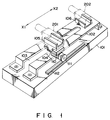
reference numeral 101 indicates a base, and a supportingplate 102 is attached to the upper surface of thebase 101 in its longitudinal direction. The supportingplate 102 constitutes a camera supporting mechanism. Both end portions of the supportingplate 102 are bent so as to be fixed onto thebase 101 by screws. A portion of the supportingplate 102 other than the end portions is therefore spaced away from thebase 101. - A
slit 103 extends from one end of the supportingplate 102 toward the other end. Theslit 103 is provided with aslide component 104 having an H-shaped side. Two concave portions of theslide component 104 are engaged with opposing edge portions of theslit 103. Theslide component 104 is thus movable along theslit 103. - A
camera holder 105 is fixed onto the upper surface of theslide component 104 to hold afirst camera body 201 in a direction perpendicular to the longitudinal direction of theslit 103. Anothercamera holder 106 is fixed to one end of thebase 101 to hold asecond camera body 202. The first andsecond camera bodies - A
motor 110 is attached to the undersurface of theslide component 104. Agear 111 of themotor 110 is engaged with arack 112 which is fixed on the upper surface of thebase 101 in the same direction as that of theslit 103. When the motor is rotated, thefirst camera body 201 is moved in the direction of arrow X1 or X2 as shown in Fig. 1. In other words, thefirst camera body 202 is controlled so as to move away from or toward thecamera body 202, while fixing the directions of the optical axes of the first andsecond camera bodies second camera bodies - The reason why only the
first camera body 201 can be moved and thesecond camera body 202 is fixed in the stereoscopic video pickup device described above, is that an image pickup operation is performed while a user is looking through a viewfinder. - A method for controlling the first and
second camera bodies - In Fig. 2,
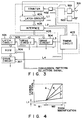
reference numeral 301 denotes an operating unit including a switch for turning on and off a power supply, a switch for starting and stopping an image pickup operation, a switch for selecting a diaphragm, and a zoom operating unit. If the zoom operating unit is operated, a zoom instruction signal is input to asystem control circuit 302. The zoom operating unit includes a zoom-in button and a zoom-out button. When the zoom-in button is depressed, thesystem control circuit 302 measures a period of time for which the zoom-in button is depressed and outputs zoom adjustment data representing the direction and amount of rotation of the motor. The zoom adjustment data is latched bydrive circuits - When the zoom adjustment data is supplied to the
drive circuits second camera bodies first camera body 201 will be described. - In Fig. 2,
reference numeral 211 denotes a zoom lens unit of thefirst camera body 201, and aflange 212 is fixed to the circumference of thezoom lens unit 211. A worm shaft 213 is engaged with theflange 212 and rotated by means of amotor 214 housed in the camera body. If themotor 214 rotates forward, thezoom lens unit 211 retreats and then a zoom-in function is carried out. If themotor 214 rotates backward, thezoom lens unit 211 moves onward and then a zoom-out function is carried out. Themotor 214 is, for example, a stepping motor which rotates in response to drive pulses supplied from thedrive circuit 303. - The zoom mechanism of the
second camera body 202 is driven in the same manner as that of thefirst camera body 201. Since thesecond camera body 202 has the same zoom mechanism as that of thefirst camera body 201, it includes azoom lens unit 221, aflange 222, aworm shaft 223, amotor 224, anddrive circuit 304 which correspond to those of the first camera body. - The zoom adjustment data is supplied to a
latch circuit 305 and then latched by thelatch circuit 305. Output data of thelatch circuit 305 is supplied to adata converter 306. The output data represents a zoom magnification. In accordance with the zoom magnification, thedata converter 306 outputs interval control data for controlling the camera interval between the first andsecond camera bodies - The interval control data is latched by a
drive circuit 307. Thedrive circuit 307 thus causes thefirst camera body 201 to move away from thesecond camera body 202 or to move toward it. - Fig. 3 illustrates the inside of the
system control circuit 302 which responds to the zoom instruction signal. - When the zoom instruction signal is input from a terminal 401, AND circuit 402 is turned on, and clocks generated from a
timing generator 403 are counted by acounter 404. Thus, time required for a zoom operation is measured. Data of the measured time is supplied to alatch circuit 405. The data is then latched by latch pulses generated from thetiming generator 403 and, in this time, polarity data indicative of zoom-in and zoom-out is also latched by thelatch circuit 405. The polarity data is supplied to the uppermost bit of thelatch circuit 405 as "1" or "0" in accordance with a user's operation of a zoom-inoperation button 501 or a zoom-outoperation button 502. More specifically, when the zoom-inoperation button 501 of theoperating unit 301 is depressed, both the polarity data "1" and the zoom instruction signal are output. When the zoom-outoperation button 502 of theoperating unit 301 is depressed, both the polarity data "0" and the zoom instruction signal are output. - When the polarity data and measured data (which corresponds to angle data representing the amount of rotation of the motor) are latched by the
latch circuit 405, these data are supplied to thedrive circuits interface 406 as zoom adjustment data and latched by thecircuits drive circuits timing generator 403. Thedrive circuits - The zoom adjustment data is latched by the
latch circuit 305. - The output data of the
latch circuit 305 is converted by thedata converter 306. (A conversion pattern of the data will be described later.) Data output from the data converter 30 includes polarity data for determining a direction of rotation of themotor 110 and conversion angle data for determining an amount of rotation of themotor 110. Various data conversion patterns of thedata converter 306 can be selected in response to conversion pattern selection signals supplied from theoperating unit 301. - Fig. 4 is a graph showing the relationship between input data converted by the
data converter 306 and output data of thedata converter 306. - Specifically, the
data converter 306 includes a ROM, and an output of thelatch circuit 305 is used as a read address. Conversion patterns A, B, C and D as shown in Fig. 4 are stored in thedata converter 306, and one of the conversion patterns can be selected by theoperating unit 301. - The conversion pattern A is suitable for stereoscopically imaging an object which is moving distantly. When the zoom magnification is low and falls within range M1 in Fig. 4, the conversion pattern A is suitable, for example, for imaging the whole of a base from which a space shuttle is launched and, in this case, the scene around the base is also imaged. When the space shuttle is launched and its altitude becomes high, an image of the space shuttle may be picked up by rapidly increasing the zoom magnification. Since the space shuttle is imaged largely on the entire screen, the shuttle can stereoscopically be imaged if the interval between the first and
second camera bodies motor 110 so that the interval between the first and second camera bodies is quickly enlarged. - The conversion pattern B is suitable for imaging a car race. The ratio of variation in the zoom magnification to variation in the camera interval is 1 to 1 in range M2 of the zoom magnification. If the zoom magnification and camera interval are so controlled, an image of one of cars racing on a circuit can stereoscopically be picked up.
- The conversion pattern D is suitable for imaging a near object. For example, such a near object is a person moving indoors. When the object is imaged, a stereoscopic image pickup effect can be obtained without greatly changing the camera interval. A camera interval M1 is a distance between the first and
second camera bodies - The conversion pattern C is suitable for imaging a near scene or the like.
- In the first embodiment described above, as shown in Fig. 2, even though the
first camera body 201 is moved in the X1 or X2 direction, the optical axes Y1 and Y2 of the first andsecond camera bodies - The present invention is not limited to the first embodiment.
- In the first embodiment, the zoom adjustment data output from the
system control circuit 302 includes the polarity data representing the direction of rotation of the motor and the angle data representing the amount of rotation of the motor. - However, the zoom adjustment data may include other data, that is, the polarity data representing the direction of rotation of the motor and a mere zoom designation code. When the zoom adjustment data includes the zoom designation code, the amount of rotation of the motor is determined by a period of time for which the zoom designation code is output. The polarity data output from the
latch circuit 305 is input to a predetermined bit of thedrive circuit 307 as it is. - Assume that zoom adjustment data including a polarity bit "1" or "0" and a zoom designation code "001" is output from the
system control circuit 302 in Fig. 5. The zoom designation code is generated by depressing the zoom-in and zoom-outoperation buttons operation button 501 is depressed, and the polarity bit "0" is obtained when the zoom-outoperation button 502 is depressed. - The
drive circuits - The
system control circuit 302 supplies a latch pulse to thelatch circuit 305. The zoom adjustment data is thus latched by thelatch circuit 305. - The
data converter 306 includes acounter 601. Thecounter 601 starts counting clocks from when the zoom adjustment data is output from thesystem control circuit 302 and, in other words, it measures a period of time for which the zoom adjustment data exists. Since zoom adjustment is continued during the period of time, the measured time represents information of an amount of zoom adjustment (zoom magnification). - When the zoom adjustment data disappears, the data measured by the
counter 501 is latched by alatch circuit 602. The measured data is then input to an address of aROM 603 for its conversion. Data output from theROM 603 is supplied to a preset input terminal of adown counter 604. The down counter 604 counts down the data output from theROM 603 as an initial value in response to the clocks. If the outputs of thedown counter 604 are all "0", an all-zero detector 605 detects it and agate circuit 607 is turned off. - The
gate circuit 607 serves to output the zoom adjustment data from thelatch circuit 305 and supply it to thedrive circuit 307. The time required for supplying the zoom adjustment data to the drive circuit is controlled by an output signal of the all-zero detector 605. If the output data of theROM 603 is preset to thedown counter 604, the output of the all-zero detector 605 becomes low in level and thegate circuit 607 is turned on. If the outputs of thedown counter 604 are all "0," the output of the all-zero detector 605 becomes high in level and thegate circuit 607 is turned off. - The zoom adjustment data is thus output from the
gate circuit 607, and a period of time for which the zoom adjustment data exists at an input terminal of thedrive circuit 307 is proportionate to the count value of thedown counter 604. More specifically, in the zoom-in operation, when the preset value of thedown counter 604 is large, the ON-state time of thegate circuit 607 is long, and the camera interval is enlarged in proportion to a period of the ON-state time. When the preset value of thedown counter 604 is small, the ON-state time of thegate circuit 607 is short, and the camera interval is slightly enlarged. - In the zoom-out operation, the camera interval is so controlled that it becomes narrow.
- In the second embodiment shown in Fig. 5, the same advantage as that of the first embodiment can be obtained. Conversion data of a plurality of patterns analogous to the patterns shown in Fig. 4, is stored in the
ROM 603. One of the patterns is selected in response to the selection signals supplied from the operating unit. - The present invention is not limited to the second embodiment. Various modifications can be made to the means for supplying control data to the
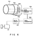
drive circuit 307 to control an interval between the motors. Further, various modifications can be made to the mechanism for moving thefirst camera body 201. - Fig. 6 shows a third embodiment of the present invention. In this embodiment, when zoom is manually adjusted, the magnification of the zoom is detected, and control data is supplied to the
drive circuit 307. - A
zoom lens unit 701 is provided with aring 702 for zoom adjustment. The amount of rotation of thering 702 and the amount of the zoom adjustment are detected by arotation angle detector 703. Therotation angle detector 703 is arranged at a fixed position of the body of the zoom lens unit and includes a plurality of switches S1, S2, S3, S4, ... which are selectively short-circuited by a projectingportion 704 of thering 702. The rotation position of thering 702, that is, the amount of the zoom adjustment can be determined by detecting which of the switches is short-circuited. The outputs of the switches S1, S2, S3, S4, ... are supplied to adata generation circuit 705. Data output from thedata generation circuit 705 is converted by thedata converter 306 and the converted data is input to thedrive circuit 307 of themotor 110. - In the above embodiments, the
first camera body 201 can be moved. However, not the first camera body but thesecond camera body 202 can be moved, and both the first andsecond camera bodies - As has been described above, according to the present invention, the information of the zoom mechanisms of the camera bodies is used for controlling the distance between the camera bodies and, even though the distance between the cameras and object is long, an image of the object can be stereoscopically picked up.
Claims (4)
- A stereoscopic video pickup device comprising:
a first camera (201) body including a first zoom mechanism;
a second camera (202) body including a second zoom mechanism;
a camera supporting mechanism (101 to 106) for supporting at least said first camera body so that said first and second camera bodies are horizontally arranged in substantially a same direction, an angle between optical axes of said first and second camera bodies is fixed, and said first camera body is moved away from said second camera body and toward said second camera body;
drive means (110, 111, 112) including a camera interval control motor, for moving said first camera body away from and toward said second camera body;
zoom control means (212, 213, 214, 222, 223, 224) for outputting zoom adjustment data to control both said first and second zoom mechanisms; and
data conversion means (206) for converting the zoom adjustment data output from said zoom control means into camera interval control data to drive said camera interval control motor. - The device according to claim 1, characterized in that said data conversion means (306) includes a plurality of conversion patterns which are selectively used in accordance with selection data output from an operating unit.
- The device according to claim 2, characterized in that one of said conversion patterns is a first nonlinear pattern which gently changes when the zoom adjustment data is smaller than a predetermined value and sharply changes when the zoom adjustment data exceeds the predetermined value.
- The device according to claim 2, characterized in that one of said conversion patterns is a second nonlinear pattern which gently changes when the zoom adjustment data is smaller than a predetermined value and changes at a same speed as the zoom adjustment data changes when the zoom adjustment data exceeds the predetermined value.
Applications Claiming Priority (2)
| Application Number | Priority Date | Filing Date | Title |
|---|---|---|---|
| JP213179/90 | 1990-08-10 | ||
| JP2213179A JPH0666968B2 (en) | 1990-08-10 | 1990-08-10 | Stereoscopic video imaging device |
Publications (3)
| Publication Number | Publication Date |
|---|---|
| EP0472015A2 true EP0472015A2 (en) | 1992-02-26 |
| EP0472015A3 EP0472015A3 (en) | 1992-03-04 |
| EP0472015B1 EP0472015B1 (en) | 1995-12-27 |
Family
ID=16634854
Family Applications (1)
| Application Number | Title | Priority Date | Filing Date |
|---|---|---|---|
| EP91112779A Expired - Lifetime EP0472015B1 (en) | 1990-08-10 | 1991-07-30 | Stereoscopic video pickup device |
Country Status (5)
| Country | Link |
|---|---|
| EP (1) | EP0472015B1 (en) |
| JP (1) | JPH0666968B2 (en) |
| KR (1) | KR920005597A (en) |
| CA (1) | CA2048867A1 (en) |
| DE (1) | DE69115793T2 (en) |
Cited By (4)
| Publication number | Priority date | Publication date | Assignee | Title |
|---|---|---|---|---|
| EP0827349A1 (en) * | 1996-08-27 | 1998-03-04 | Kanji Murakami | Multidirectional image pickup apparatus using a plurality of image pickup cameras |
| ITRM20100367A1 (en) * | 2010-07-07 | 2012-01-07 | Francesco Gasperoni | SUPPORT DEVICE FOR A SYSTEM FOR STEREOSCOPIC SHOOTING |
| US8189100B2 (en) | 2006-07-25 | 2012-05-29 | Qualcomm Incorporated | Mobile device with dual digital camera sensors and methods of using the same |
| JP2012253472A (en) * | 2011-06-01 | 2012-12-20 | Yoshihiko Kitamura | Three-dimensional camera |
Families Citing this family (3)
| Publication number | Priority date | Publication date | Assignee | Title |
|---|---|---|---|---|
| KR101121421B1 (en) * | 2010-02-23 | 2012-03-20 | 주식회사 빅아이 | Method and computer readable recording medium for providing optimal distance between cameras in stereoscopic video production and apparatus for producing stereoscopic video |
| JP2011250177A (en) * | 2010-05-27 | 2011-12-08 | Toshiba Corp | Camera module and image recording method |
| JP6391880B2 (en) * | 2016-05-20 | 2018-09-19 | 誠 高宮 | Camera system |
Citations (3)
| Publication number | Priority date | Publication date | Assignee | Title |
|---|---|---|---|---|
| US2417446A (en) * | 1941-08-01 | 1947-03-18 | Bell Telephone Labor Inc | Stereotelevision and television range finding |
| EP0146476A2 (en) * | 1983-12-19 | 1985-06-26 | Thomson-Csf | Device for stereoscopic pictures with a base-defining system |
| GB2168565A (en) * | 1984-12-07 | 1986-06-18 | Max Robinson | Generation of apparently three-dimensional images |
-
1990
- 1990-08-10 JP JP2213179A patent/JPH0666968B2/en not_active Expired - Lifetime
-
1991
- 1991-07-30 EP EP91112779A patent/EP0472015B1/en not_active Expired - Lifetime
- 1991-07-30 DE DE69115793T patent/DE69115793T2/en not_active Expired - Lifetime
- 1991-08-09 CA CA002048867A patent/CA2048867A1/en not_active Abandoned
- 1991-08-09 KR KR1019910013794A patent/KR920005597A/en not_active Application Discontinuation
Patent Citations (3)
| Publication number | Priority date | Publication date | Assignee | Title |
|---|---|---|---|---|
| US2417446A (en) * | 1941-08-01 | 1947-03-18 | Bell Telephone Labor Inc | Stereotelevision and television range finding |
| EP0146476A2 (en) * | 1983-12-19 | 1985-06-26 | Thomson-Csf | Device for stereoscopic pictures with a base-defining system |
| GB2168565A (en) * | 1984-12-07 | 1986-06-18 | Max Robinson | Generation of apparently three-dimensional images |
Cited By (4)
| Publication number | Priority date | Publication date | Assignee | Title |
|---|---|---|---|---|
| EP0827349A1 (en) * | 1996-08-27 | 1998-03-04 | Kanji Murakami | Multidirectional image pickup apparatus using a plurality of image pickup cameras |
| US8189100B2 (en) | 2006-07-25 | 2012-05-29 | Qualcomm Incorporated | Mobile device with dual digital camera sensors and methods of using the same |
| ITRM20100367A1 (en) * | 2010-07-07 | 2012-01-07 | Francesco Gasperoni | SUPPORT DEVICE FOR A SYSTEM FOR STEREOSCOPIC SHOOTING |
| JP2012253472A (en) * | 2011-06-01 | 2012-12-20 | Yoshihiko Kitamura | Three-dimensional camera |
Also Published As
| Publication number | Publication date |
|---|---|
| JPH0666968B2 (en) | 1994-08-24 |
| EP0472015B1 (en) | 1995-12-27 |
| JPH0495489A (en) | 1992-03-27 |
| EP0472015A3 (en) | 1992-03-04 |
| DE69115793D1 (en) | 1996-02-08 |
| CA2048867A1 (en) | 1992-02-11 |
| DE69115793T2 (en) | 1996-05-23 |
| KR920005597A (en) | 1992-03-28 |
Similar Documents
| Publication | Publication Date | Title |
|---|---|---|
| US7218849B2 (en) | Lens device having a controller for controlling optical elements and photographing apparatus including the lens device | |
| JPH03502840A (en) | camera | |
| KR100207670B1 (en) | Video camera unified with a still camera | |
| JP2833169B2 (en) | Imaging device | |
| EP0472015B1 (en) | Stereoscopic video pickup device | |
| EP0425243B1 (en) | Lens control apparatus | |
| US20030173518A1 (en) | Visible/infrared imaging camera | |
| JPH0829669A (en) | Camera | |
| JPH04178607A (en) | Automatic focusing device | |
| JPH06300962A (en) | Automatic focusing device for camera | |
| JPH0524486B2 (en) | ||
| JP2005092072A (en) | Zoom lens barrel and digital camera | |
| JP2000270256A (en) | Electronic endoscope with variable power function | |
| JP3429050B2 (en) | Focus adjustment device for TV camera | |
| JP2760669B2 (en) | Imaging device having lens reference position adjusting device | |
| JP2612711B2 (en) | camera | |
| US11575836B2 (en) | Imaging device and camera body | |
| JPH11305115A (en) | Electronic camera | |
| JP2833725B2 (en) | Electronic still camera ranging device | |
| JPH0785124B2 (en) | Automatic focus adjustment device | |
| JP2981481B2 (en) | Video camera with automatic focusing means | |
| JP2979182B2 (en) | Focus lens drive device, focus lens and aperture drive device | |
| JPH0813099B2 (en) | Imaging device | |
| JP2024052503A (en) | Lens device and imaging device | |
| JPS6315859Y2 (en) |
Legal Events
| Date | Code | Title | Description |
|---|---|---|---|
| PUAI | Public reference made under article 153(3) epc to a published international application that has entered the european phase |
Free format text: ORIGINAL CODE: 0009012 |
|
| PUAL | Search report despatched |
Free format text: ORIGINAL CODE: 0009013 |
|
| 17P | Request for examination filed |
Effective date: 19911113 |
|
| AK | Designated contracting states |
Kind code of ref document: A2 Designated state(s): DE FR GB |
|
| AK | Designated contracting states |
Kind code of ref document: A3 Designated state(s): DE FR GB |
|
| 17Q | First examination report despatched |
Effective date: 19940624 |
|
| GRAA | (expected) grant |
Free format text: ORIGINAL CODE: 0009210 |
|
| AK | Designated contracting states |
Kind code of ref document: B1 Designated state(s): DE FR GB |
|
| ET | Fr: translation filed | ||
| REF | Corresponds to: |
Ref document number: 69115793 Country of ref document: DE Date of ref document: 19960208 |
|
| PLBE | No opposition filed within time limit |
Free format text: ORIGINAL CODE: 0009261 |
|
| STAA | Information on the status of an ep patent application or granted ep patent |
Free format text: STATUS: NO OPPOSITION FILED WITHIN TIME LIMIT |
|
| 26N | No opposition filed | ||
| REG | Reference to a national code |
Ref country code: GB Ref legal event code: IF02 |
|
| PGFP | Annual fee paid to national office [announced via postgrant information from national office to epo] |
Ref country code: FR Payment date: 20100820 Year of fee payment: 20 |
|
| PGFP | Annual fee paid to national office [announced via postgrant information from national office to epo] |
Ref country code: GB Payment date: 20100728 Year of fee payment: 20 |
|
| PGFP | Annual fee paid to national office [announced via postgrant information from national office to epo] |
Ref country code: DE Payment date: 20100930 Year of fee payment: 20 |
|
| REG | Reference to a national code |
Ref country code: DE Ref legal event code: R071 Ref document number: 69115793 Country of ref document: DE |
|
| REG | Reference to a national code |
Ref country code: DE Ref legal event code: R071 Ref document number: 69115793 Country of ref document: DE |
|
| REG | Reference to a national code |
Ref country code: GB Ref legal event code: PE20 Expiry date: 20110729 |
|
| PG25 | Lapsed in a contracting state [announced via postgrant information from national office to epo] |
Ref country code: GB Free format text: LAPSE BECAUSE OF EXPIRATION OF PROTECTION Effective date: 20110729 |
|
| PG25 | Lapsed in a contracting state [announced via postgrant information from national office to epo] |
Ref country code: DE Free format text: LAPSE BECAUSE OF EXPIRATION OF PROTECTION Effective date: 20110731 |