EP0387801A2 - An exposure compensation apparatus for a radiographic equipment - Google Patents
An exposure compensation apparatus for a radiographic equipment Download PDFInfo
- Publication number
- EP0387801A2 EP0387801A2 EP90104741A EP90104741A EP0387801A2 EP 0387801 A2 EP0387801 A2 EP 0387801A2 EP 90104741 A EP90104741 A EP 90104741A EP 90104741 A EP90104741 A EP 90104741A EP 0387801 A2 EP0387801 A2 EP 0387801A2
- Authority
- EP
- European Patent Office
- Prior art keywords
- transmittance
- radiation
- data
- image
- local
- Prior art date
- Legal status (The legal status is an assumption and is not a legal conclusion. Google has not performed a legal analysis and makes no representation as to the accuracy of the status listed.)
- Granted
Links
Images


Classifications
-
- H—ELECTRICITY
- H05—ELECTRIC TECHNIQUES NOT OTHERWISE PROVIDED FOR
- H05G—X-RAY TECHNIQUE
- H05G1/00—X-ray apparatus involving X-ray tubes; Circuits therefor
- H05G1/08—Electrical details
- H05G1/26—Measuring, controlling or protecting
-
- G—PHYSICS
- G21—NUCLEAR PHYSICS; NUCLEAR ENGINEERING
- G21K—TECHNIQUES FOR HANDLING PARTICLES OR IONISING RADIATION NOT OTHERWISE PROVIDED FOR; IRRADIATION DEVICES; GAMMA RAY OR X-RAY MICROSCOPES
- G21K1/00—Arrangements for handling particles or ionising radiation, e.g. focusing or moderating
- G21K1/02—Arrangements for handling particles or ionising radiation, e.g. focusing or moderating using diaphragms, collimators
- G21K1/04—Arrangements for handling particles or ionising radiation, e.g. focusing or moderating using diaphragms, collimators using variable diaphragms, shutters, choppers
-
- H—ELECTRICITY
- H05—ELECTRIC TECHNIQUES NOT OTHERWISE PROVIDED FOR
- H05G—X-RAY TECHNIQUE
- H05G1/00—X-ray apparatus involving X-ray tubes; Circuits therefor
- H05G1/08—Electrical details
- H05G1/26—Measuring, controlling or protecting
- H05G1/30—Controlling
- H05G1/38—Exposure time
- H05G1/42—Exposure time using arrangements for switching when a predetermined dose of radiation has been applied, e.g. in which the switching instant is determined by measuring the electrical energy supplied to the tube
- H05G1/44—Exposure time using arrangements for switching when a predetermined dose of radiation has been applied, e.g. in which the switching instant is determined by measuring the electrical energy supplied to the tube in which the switching instant is determined by measuring the amount of radiation directly
-
- H—ELECTRICITY
- H05—ELECTRIC TECHNIQUES NOT OTHERWISE PROVIDED FOR
- H05G—X-RAY TECHNIQUE
- H05G1/00—X-ray apparatus involving X-ray tubes; Circuits therefor
- H05G1/08—Electrical details
- H05G1/60—Circuit arrangements for obtaining a series of X-ray photographs or for X-ray cinematography
Definitions
- This invention relates to an exposure compensation apparatus for use in a radiographic equipment for medical diagnosis.
- a radiation source applies radiation, generally X-rays, to an object, generally a covered organ in a living human body, to form and record an image of the object on an image screen, such as an screen-film installed behind the object.
- the object In X-ray diagnosis, however, the object, a chest for example, has extremely great variations in anatomical thickness and tissue hardness, thus causing a great deal of variance of X-ray absorption by portions of the object.
- a local intensity modulator is installed between the radiation source and the object, and is used for the purpose of modulating the intensity of the radiation to each location of the object, whereby the modulation is based on transmittance datum of each location measured by test radiation that is radiated before or at substantially the same time of said radiation, as referred to in the Japanese patent publication Nos. 1987-129034 and 1988-189853.
- a conventional compensation apparatus has a disadvantage in that even if the original image of the organ has the assymmetric density distribution showing the presence of the diseased area, density difference between the corresponding right and left portions is equalized by the compensation. This increases the difficulty in diagnosis and may cause a wrong diagnosis.
- the object of the present invention is to provide a radiographic equipment having a local compensation capability which retains the original density difference between the corresponding locations of the organ to avoid making the wrong diagnosis above mentioned.
- This invention is directed to the provision of an exposure compensation apparatus of a radiographic apparatus to control a local intensity modulator of the radiographic apparatus comprising a detecting means to measure original transmittance of each location of an object, a right-left reversion means to reverse an arrangement of the locations in the original transmittance data of the corresponding locations in a predetermined direction, an averaging means fo obtaining an averaged transmittance by averaging the original data and the reversed data, and a control means to control the local intensity modulator of the radiographic apparatus according to the averaged control signal from the averaging means.
- the original locations of transmittance in the predetermined direction is reversed in relation to a center line of symmetry, the transmittance data and the reversed data are then averaged in relation to each pair of corresponding symmetrical locations of the image to generate an averaged local compensation signal, and thus the compensation based on the averaged compensation signal has a symmetric characteristic in the predetermined direction.
- Fig. 1 is a block diagram of a control unit indicating an embodiment of the present invention
- Fig. 2 is a perspective view of radiographic equipment
- Figs. 3-1, 3-2, and 3-3 show embodiments of a transmittance detection means
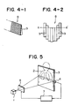
- Figs. 4-1 and 4-2 show structures of a local intensity modulator
- Fig. 5 is a perspective view of another embodiment of radiographic equipment
- Fig. 6 shows the relationship between transmittance and required transmittance
- Fig.7 shows the relationship between transmittance and attenuation
- Fig. 8 shows an example of chest radiography
- Fig. 9 shows an example of transmittance data
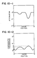
- Figs. 10-1, 10-2, and 10-3 show control examples when the R-L reversion processing 12 and the mean processing 13 in Fig.
- Figs. 11-1, 11-2, 11-3, 11-4, and 11-5 show control examples when the R-L reversion processing and the mean processing are performed;
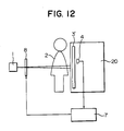
- Fig. 12 is a perspective view of a radiographic equipment using an image conversion panel; and
- Fig. 13 is a schematic view of an image reader.
- X-ray radiation is applied to an object 2 from the radiation source 1, and an image is formed and recorded according to the intensity of transmitted radiation by the screen-film 3 installed behind the object 2.
- the screen-film 3 is a combination of a fluorescent layer and a photosensitive film coated with a silver-salt photosentisizer, wherein the former converts the X-rays to visible rays to be recorded on the film.
- the radiographic process of the invention consists of two steps.
- a weak and constant radiation is a applied to the object 2 from the radiation source 1 and intensity of transmitted radiation is measured at each location of the image to be used as transmittance data of the object later.
- a strong and compensated radiation is applied to the object 2 from the radiation source 1 to form and record an image of the object 2 on the screen-film 3 to be used for diagnosis.
- a line detector 4 is installed behind the object 2 as shown in Fig. 3-1, the transmittance at each part of the object 2 is detected by scanning the line detector 4, and the detection results are stored in a memory of a control unit 7.
- the line detector 4 may be scanned in synchronization with a fan beam generated from the radiation fan beam generator.
- the image intensifier 5 may be used instead of the line detector 4 so as to intensify the image of the object 2, and the image is then scanned TV camera 6 to be stored in a memory of the control unit 7 as the transmittance data.
- the radiation for such data storage may be weak as mentioned above, and the space resolution of the line detector 4 and of the TV camera 6 may be low.
- the local compensation unit 8 is installed between the radiation source 1 and the object 2 as shown in Fig. 2, and the local compensation unit 8 is controlled by the control unit 7.
- the local intensity modulator 8 is controlled so as to lower the radiation intensity to that for a lung part, compared with the intensity for other parts, based on the transmittance data stored in the control unit 7.
- FIG. 4-1 and 4-2 An example of the structure of the local intensity modulator 8 is shown in Fig. 4-1 and 4-2.
- a plurality of the wedge-shaped blades 9 of a radiation-absorptive substance is stacked in one row as in Fig. 4-1, and each blade moves above and under the fan beam path a-a′ as in Fig. 4-2, so as to locally modulate the intensity of radiation.
- It is desirable that the number of blades 9 is equal to the number of pixels of the line detector 4. Therefore, when the number of pixels of the line detector 4 is 2000, the maximum number of blades is 2000.
- the spacial frequency of the compensation is lowered by the averaging processing, necessary number of blades which can respond to the spacial frequency is also lowered.
- the detection of the transmittance at each part of the object 2 may be performed simultaneously with the compensation of the radiation intensity according to the detected data during image formation wherein the radiation through the object 2 is applied to the screen film 3.
- the object 2 is located in front of the screen film 3 from the beginning, and the object 2 is scanned on the screen film 3 by the radiation fan beam generated by radiation source 1.
- the transmittance at each part is detected by the line detector 4 which moves synchronizing with the scan of the fan beam behind the screen film 3, the detected transmittance is immediately fed back to the local intensity modulator 8 via the control unit 7, and an image is formed on the screen film by one scanning with the local compensation of compensating the radiation intensity at each location of the object 2.
- a pencil beam may be used instead of the fan beam.
- the configuration of the control unit 7 related to the present invention will be described hereunder with reference to Fig. 1.
- the control unit 7 comprises the memory 11 which stores transmittance data from the line detector 4 or the TV camera 6; the R-L reversion unit 12 which serves as a right-left reversion means for reversing a location arrangement of the transmittance data from the memory 11; the averaging unit 13 which serves as an averaging means for overlapping and averaging the transmittance data from the memory 11 and the reversed transmittance data from the R-L reversion unit 12, and a local compensation signal generator 14 which generates a local compensation signal from the averaged transmittance data obtained by the averaging unit 13 and controls the local intensity modulator 8 according to the generated result.
- An A/D converter and a D/A converter may be additionally used when necessary.
- a non-linear conversion process such as a logarithmic conversion of transmittance data, may be inserted, and both an analog means and digital means may be used in the above processes.
- the original transmittance data from the memory may sequentially pass, sequentially through the local compensation signal generator, R-L reversion unit, and then averaging unit.
- the dynamic range of the image intensity can be compressed.
- Fig. 6 shows the relationship between the transmittance data of the object 2 and the required transmission of radiation for radiography.
- Fig. 7 shows the relationship between the transmittance data of the object 2 and the required attenuation by the local intensity modulator.
- the local compensation signal generator 14 generates a local compensation signal base on the relationship in Figs. 6 and 7 according to the transmittance data at each part of the object 2, and controls the local intensity modulator 8 according to the generated data.
- the functions of the R-L reversion unit 12 and the averaging means 13 which are performed before starting the above processing are as follows: When a shadow exists in the left lung in Fig. 8 due to a disease in chest radiography and the radiation fan beam is applied on the line a-a′ in the figure, the transmittance data from the line detector 4 is as shown in Fig. 9.
- a signal which is reversed by the R-L reversion unit 12 is as shown in Fig. 11-1.
- a signal obtained by the averaging means 13 is an average of the transmittances in Figs. 9 and 11-1, and is as shown in Fig. 11-2.
- the attenuation by the local compensation unit 8 is as shown in Fig. 11-3 from the relationship in Fig. 7.
- the radiation intensity at each part is controlled by the local intensity modulator 8 transmitted radiation distributes as shown in Fig. 11-4.
- the screen film 3 is used as an imaging screen.
- a radiation image conversion panel 3′ for example, made of a photo-stimulated fluorescent material which stores and records radiation images may be used to allow a radiation image reader 20 to read the radiation images.
- the image reader 20 may serve as a line detector 4.
- the line detector 4 it is desirable to install the detector between the radiation source 1 and the conversion panel 3′.
- the materials indicated hereunder in i) to vi) below may be used, for example, as a photo-stimulated fluorescent material used as a radiation image conversion panel.
- Fig. 13 shows an example of the radiation image reader 20.
- a light source 21 for generating an excitation light for example, a semiconductor laser beam
- a driver circuit such as the laser driver 22.
- a beam generated from the light source 21 reaches the deflector 27 via the monochromatic light filter 23, the split mirror 24, the beam shaping optical system 25, and the mirror 26.
- the deflector 27 comprises a galvanomirror which is driven by the deflector driver 28, and deflects the above beam at a predetermined angle in the scan region.
- the deflected beam is adjusted by a f ⁇ lens 29 so that the beam is kept to move at a predetermined speed on the scanning lines, and scans on the conversion panel 3′, where the dynamic range of the image data which transmits through the object as mentioned above is stored and recorded in a compressed state, in the direction of the arrow "a" via the mirror 30.
- the conversion panel 3′ moves simultaneously in the subscanning direction (in the direction of the arrow b) by an appropriate means to allow for scanning on the overall surface.
- a photo-stimulated light generated from the conversion panel 3′ which is scanned by the above beam is condensed by the condenser 32, and reaches the beam receiving unit 34 comprising a photo-electric converter such as a photo-electric multiplier via the filter 33 which allows only the wave length region of the photo-stimulated light to pass through, and is converted to an analog electric signal (an image signal).
- a photo-electric converter such as a photo-electric multiplier via the filter 33 which allows only the wave length region of the photo-stimulated light to pass through, and is converted to an analog electric signal (an image signal).
- a high voltage is supplied to the photo-electric multiplier from the power source 35; an image signal which is generated from the photo-electric multiplier as a current is amplified by the current-voltage converting multiplier 36.
- a voltage signal thus obtained passes through the Log converter 37 which converts the signal to a light intensity signal and the sample & hold circuit 38, is converted to a digital signal by the A/D converter 39, and is stored in the memory 40.
- This memory 40 is connected to a CPU 41 which performs digital operations, and the CPU 41 can be connected to external equipment via an interface 42, such as a large scale computer or a minicomputer for storing and processing data, a CRT display for outputting images, or various hard copy creating equipment.
- the CPU operates and transfers data stored in the memory 40.
- a control signal from the control unit 7 may be supplied to one of the following units, namely; the laser driver 22, the power source 35 for the photo-electric multiplier, or the current-voltage converting amplifier 36.
- the image reader 20 may correct the obtained image signal by the signal from the control unit 7.
- the present invention performs exposure compensation by reversing the detected transmittance data in the right and left direction, averages the original data and the right-left reversed data, and controls the radiation intensity at each part of the object according to the averaged data, and so the exposure compensation is symmetrical on the right and left.
- the difference in density between the right and left parts of an object is kept to make the image clear and the resultant effect is the elimination of a wrong diagnosis.
Abstract
Description
- This invention relates to an exposure compensation apparatus for use in a radiographic equipment for medical diagnosis.
- In conventional radiographic apparatus, a radiation source applies radiation, generally X-rays, to an object, generally a covered organ in a living human body, to form and record an image of the object on an image screen, such as an screen-film installed behind the object.
- In X-ray diagnosis, however, the object, a chest for example, has extremely great variations in anatomical thickness and tissue hardness, thus causing a great deal of variance of X-ray absorption by portions of the object.
- As a result, only a small part of the object image is provided with an appropriate exposure amount and a greater part of the image is out of the proper exposure range, and this causes a large loss of image information, namely a large loss in diagnosis value.
- To meet the above situation a local intensity modulator is installed between the radiation source and the object, and is used for the purpose of modulating the intensity of the radiation to each location of the object, whereby the modulation is based on transmittance datum of each location measured by test radiation that is radiated before or at substantially the same time of said radiation, as referred to in the Japanese patent publication Nos. 1987-129034 and 1988-189853.
- It has been empirically recognized that in an X-ray diagnosis of an organ of a human body having a symmetrical form in relation to a line of symmetry, a density difference of a radiographic image between corresponding right and left locations of the organ is sometimes a key to finding a focal area of a diseased organ. A lung is a typical example.
- A conventional compensation apparatus, however, has a disadvantage in that even if the original image of the organ has the assymmetric density distribution showing the presence of the diseased area, density difference between the corresponding right and left portions is equalized by the compensation. This increases the difficulty in diagnosis and may cause a wrong diagnosis.
- The object of the present invention is to provide a radiographic equipment having a local compensation capability which retains the original density difference between the corresponding locations of the organ to avoid making the wrong diagnosis above mentioned.
- This invention is directed to the provision of an exposure compensation apparatus of a radiographic apparatus to control a local intensity modulator of the radiographic apparatus comprising a detecting means to measure original transmittance of each location of an object, a right-left reversion means to reverse an arrangement of the locations in the original transmittance data of the corresponding locations in a predetermined direction, an averaging means fo obtaining an averaged transmittance by averaging the original data and the reversed data, and a control means to control the local intensity modulator of the radiographic apparatus according to the averaged control signal from the averaging means.
- In the above configuration of the invention, the original locations of transmittance in the predetermined direction is reversed in relation to a center line of symmetry, the transmittance data and the reversed data are then averaged in relation to each pair of corresponding symmetrical locations of the image to generate an averaged local compensation signal, and thus the compensation based on the averaged compensation signal has a symmetric characteristic in the predetermined direction.
- Fig. 1 is a block diagram of a control unit indicating an embodiment of the present invention; Fig. 2 is a perspective view of radiographic equipment; Figs. 3-1, 3-2, and 3-3 show embodiments of a transmittance detection means; Figs. 4-1 and 4-2 show structures of a local intensity modulator; Fig. 5 is a perspective view of another embodiment of radiographic equipment; Fig. 6 shows the relationship between transmittance and required transmittance; Fig.7 shows the relationship between transmittance and attenuation; Fig. 8 shows an example of chest radiography; Fig. 9 shows an example of transmittance data; Figs. 10-1, 10-2, and 10-3 show control examples when the
R-L reversion processing 12 and the mean processing 13 in Fig. 1 are not performed; Figs. 11-1, 11-2, 11-3, 11-4, and 11-5 show control examples when the R-L reversion processing and the mean processing are performed; Fig. 12 is a perspective view of a radiographic equipment using an image conversion panel; and Fig. 13 is a schematic view of an image reader. - In a radiographic equipment as shown in Fig. 2, X-ray radiation is applied to an
object 2 from the radiation source 1, and an image is formed and recorded according to the intensity of transmitted radiation by the screen-film 3 installed behind theobject 2. - The screen-
film 3 is a combination of a fluorescent layer and a photosensitive film coated with a silver-salt photosentisizer, wherein the former converts the X-rays to visible rays to be recorded on the film. The radiographic process of the invention consists of two steps. - In the first step, a weak and constant radiation is a applied to the
object 2 from the radiation source 1 and intensity of transmitted radiation is measured at each location of the image to be used as transmittance data of the object later. - In the second step, a strong and compensated radiation is applied to the
object 2 from the radiation source 1 to form and record an image of theobject 2 on the screen-film 3 to be used for diagnosis. - As a transmittance detection means in the first step, a
line detector 4 is installed behind theobject 2 as shown in Fig. 3-1, the transmittance at each part of theobject 2 is detected by scanning theline detector 4, and the detection results are stored in a memory of acontrol unit 7. When a radiation fan beam generator is used as a radiation source 1 as shown in Fig. 3-2, theline detector 4 may be scanned in synchronization with a fan beam generated from the radiation fan beam generator. - As shown in Fig. 3-3, the
image intensifier 5 may be used instead of theline detector 4 so as to intensify the image of theobject 2, and the image is then scannedTV camera 6 to be stored in a memory of thecontrol unit 7 as the transmittance data. The radiation for such data storage may be weak as mentioned above, and the space resolution of theline detector 4 and of theTV camera 6 may be low. - As a local compensation means in the second step, the
local compensation unit 8 is installed between the radiation source 1 and theobject 2 as shown in Fig. 2, and thelocal compensation unit 8 is controlled by thecontrol unit 7. - As an example, as shown in Fig. 2, when the
object 2 is a human chest and a fan beam is used to radiate theobject 2 on a line area a-a′ to form and record an image on the screen-film 3, thelocal intensity modulator 8 is controlled so as to lower the radiation intensity to that for a lung part, compared with the intensity for other parts, based on the transmittance data stored in thecontrol unit 7. - An example of the structure of the
local intensity modulator 8 is shown in Fig. 4-1 and 4-2. A plurality of the wedge-shaped blades 9 of a radiation-absorptive substance is stacked in one row as in Fig. 4-1, and each blade moves above and under the fan beam path a-a′ as in Fig. 4-2, so as to locally modulate the intensity of radiation. It is desirable that the number of blades 9 is equal to the number of pixels of theline detector 4. Therefore, when the number of pixels of theline detector 4 is 2000, the maximum number of blades is 2000. When the spacial frequency of the compensation is lowered by the averaging processing, necessary number of blades which can respond to the spacial frequency is also lowered. When the number of compensation pixels is reduced to 100 by averaging, for example, 100 sheets of blades is large enough. As shown in Fig. 5, the detection of the transmittance at each part of theobject 2 may be performed simultaneously with the compensation of the radiation intensity according to the detected data during image formation wherein the radiation through theobject 2 is applied to thescreen film 3. In this case theobject 2 is located in front of thescreen film 3 from the beginning, and theobject 2 is scanned on thescreen film 3 by the radiation fan beam generated by radiation source 1. Simultaneously, the transmittance at each part is detected by theline detector 4 which moves synchronizing with the scan of the fan beam behind thescreen film 3, the detected transmittance is immediately fed back to thelocal intensity modulator 8 via thecontrol unit 7, and an image is formed on the screen film by one scanning with the local compensation of compensating the radiation intensity at each location of theobject 2. When this method is used, a pencil beam may be used instead of the fan beam. - The configuration of the
control unit 7 related to the present invention will be described hereunder with reference to Fig. 1. Thecontrol unit 7 comprises the memory 11 which stores transmittance data from theline detector 4 or theTV camera 6; theR-L reversion unit 12 which serves as a right-left reversion means for reversing a location arrangement of the transmittance data from the memory 11; the averaging unit 13 which serves as an averaging means for overlapping and averaging the transmittance data from the memory 11 and the reversed transmittance data from theR-L reversion unit 12, and a localcompensation signal generator 14 which generates a local compensation signal from the averaged transmittance data obtained by the averaging unit 13 and controls thelocal intensity modulator 8 according to the generated result. - An A/D converter and a D/A converter may be additionally used when necessary.
- In the series of the above processes, a non-linear conversion process, such as a logarithmic conversion of transmittance data, may be inserted, and both an analog means and digital means may be used in the above processes.
- As another example of the embodyments the original transmittance data from the memory may sequentially pass, sequentially through the local compensation signal generator, R-L reversion unit, and then averaging unit. By this way also, the dynamic range of the image intensity can be compressed.
- Next, the function of the
control unit 7 will be described hereunder. - Fig. 6 shows the relationship between the transmittance data of the
object 2 and the required transmission of radiation for radiography. - Fig. 7 shows the relationship between the transmittance data of the
object 2 and the required attenuation by the local intensity modulator. The localcompensation signal generator 14 generates a local compensation signal base on the relationship in Figs. 6 and 7 according to the transmittance data at each part of theobject 2, and controls thelocal intensity modulator 8 according to the generated data. The functions of theR-L reversion unit 12 and the averaging means 13 which are performed before starting the above processing are as follows:
When a shadow exists in the left lung in Fig. 8 due to a disease in chest radiography and the radiation fan beam is applied on the line a-a′ in the figure, the transmittance data from theline detector 4 is as shown in Fig. 9. - When the transmittance data in Fig. 9 is used as it is, the attenuation by the
local intensity modulator 8 is as shown in Fig. 10-1, and resultant intensity of the transmitted radiation distributes as shown in Fig. 10-2. As a result, dynamic range caused by control is as shown in Fig. 10-3. The dynamic range is compressed, but the difference in density between the right and left lungs is hard to detect. - When the
R-L reversion unit 12 and the averaging means 13 are used, the results shown in Figs. 11-1 to 11-5 are obtained. - When the transmittance data from the
line detector 4 is as shown in Fig. 9, a signal which is reversed by theR-L reversion unit 12 is as shown in Fig. 11-1. A signal obtained by the averaging means 13 is an average of the transmittances in Figs. 9 and 11-1, and is as shown in Fig. 11-2. - When the averaged transmittance data in Fig. 11-2 is used, the attenuation by the
local compensation unit 8 is as shown in Fig. 11-3 from the relationship in Fig. 7. When the radiation intensity at each part is controlled by thelocal intensity modulator 8 transmitted radiation distributes as shown in Fig. 11-4. - As a result, the change in dynamic range caused by control is as shown in Fig. 11-5, and the dynamic range is compressed keeping the difference in density between the right and left lungs.
- In the above embodiments, the
screen film 3 is used as an imaging screen. As shown in Fig. 12, however, a radiationimage conversion panel 3′, for example, made of a photo-stimulated fluorescent material which stores and records radiation images may be used to allow aradiation image reader 20 to read the radiation images. - In this case, the
image reader 20 may serve as aline detector 4. When theline detector 4 is used, it is desirable to install the detector between the radiation source 1 and theconversion panel 3′. - The materials indicated hereunder in i) to vi) below may be used, for example, as a photo-stimulated fluorescent material used as a radiation image conversion panel.
- i) An alkaline earth halide fluoride fluorescent material indicated by the general expression:
(Ba1-x-y Mgx Cay) FX:eEu²⁺
described in the Japanese patent publication No. 1980-12143 - ii) A fluorescent material indicated by the general expression:
LnOX:xA
described in the Japanese patent publication No. 1980-12144 - iii) A fluorescent material indicated by the general expression:
(Ba1-x Mg x) FX:yA
described in the Japanese patent publication No. 1980-12145 - iv) A fluorescent material indicated by the general expression:
BaFX xCe, yA
described in the Japanese patent publication No. 1980-84389 - v) A rare earth element activated dihydric metal fluorohalide fluorescent material indicated by the general expression:
M² FX·xA:yLn
described in the Japanese patent publication No. 1980-160078 - vi) An alkaline halide fluorescent material indicated by the general expression:
(M¹ X·am² X′₂·bM³ X˝₃:cA
described in the Japanese patent publication No. 1986-72087 - Fig. 13 shows an example of the
radiation image reader 20. - In the case of Fig. 13, a
light source 21 for generating an excitation light, for example, a semiconductor laser beam, is driven by a driver circuit such as thelaser driver 22. A beam generated from thelight source 21 reaches thedeflector 27 via the monochromaticlight filter 23, thesplit mirror 24, the beam shapingoptical system 25, and themirror 26. Thedeflector 27 comprises a galvanomirror which is driven by thedeflector driver 28, and deflects the above beam at a predetermined angle in the scan region. The deflected beam is adjusted by afϑ lens 29 so that the beam is kept to move at a predetermined speed on the scanning lines, and scans on theconversion panel 3′, where the dynamic range of the image data which transmits through the object as mentioned above is stored and recorded in a compressed state, in the direction of the arrow "a" via themirror 30. Theconversion panel 3′ moves simultaneously in the subscanning direction (in the direction of the arrow b) by an appropriate means to allow for scanning on the overall surface. A photo-stimulated light generated from theconversion panel 3′ which is scanned by the above beam is condensed by thecondenser 32, and reaches thebeam receiving unit 34 comprising a photo-electric converter such as a photo-electric multiplier via thefilter 33 which allows only the wave length region of the photo-stimulated light to pass through, and is converted to an analog electric signal (an image signal). A high voltage is supplied to the photo-electric multiplier from thepower source 35; an image signal which is generated from the photo-electric multiplier as a current is amplified by the current-voltage converting multiplier 36. A voltage signal thus obtained passes through theLog converter 37 which converts the signal to a light intensity signal and the sample & holdcircuit 38, is converted to a digital signal by the A/D converter 39, and is stored in thememory 40. Thismemory 40 is connected to aCPU 41 which performs digital operations, and theCPU 41 can be connected to external equipment via aninterface 42, such as a large scale computer or a minicomputer for storing and processing data, a CRT display for outputting images, or various hard copy creating equipment. The CPU operates and transfers data stored in thememory 40. - For compressing the dynamic range of the image intensity, a control signal from the
control unit 7 may be supplied to one of the following units, namely; thelaser driver 22, thepower source 35 for the photo-electric multiplier, or the current-voltage converting amplifier 36. Theimage reader 20 may correct the obtained image signal by the signal from thecontrol unit 7. - As mentioned above, the present invention performs exposure compensation by reversing the detected transmittance data in the right and left direction, averages the original data and the right-left reversed data, and controls the radiation intensity at each part of the object according to the averaged data, and so the exposure compensation is symmetrical on the right and left. The difference in density between the right and left parts of an object is kept to make the image clear and the resultant effect is the elimination of a wrong diagnosis.
Claims (1)
- An exposure compensation apparatus for use in a radiographic equipment, wherein said radiographic equipment has a local intensity modulator to modulate a local intensity of radiation,
said exposure compensation apparatus comprising;
a detecting means to detect a transmittance of radiation through an object at each location of the object to be used as original transmittance data,
a right-left reversion means to process a set of original transmittance data of the locations on a line in a predetermined direction, whereby said reversion means reverses a location arrangement the transmittance data on the line to obtain reversed data,
an averaging means to obtain an averaged transmittance by averaging a pair of the original trancemittance and the reversed transmittance of the same location,
a local compensation signal generator to control the local intensity modulator of the radiographic equipment, based on the averaged transmittance from the averaging means.
Applications Claiming Priority (2)
| Application Number | Priority Date | Filing Date | Title |
|---|---|---|---|
| JP59698/89 | 1989-03-14 | ||
| JP1059698A JP2741236B2 (en) | 1989-03-14 | 1989-03-14 | Exposure compensation device for radiation imaging equipment |
Publications (3)
| Publication Number | Publication Date |
|---|---|
| EP0387801A2 true EP0387801A2 (en) | 1990-09-19 |
| EP0387801A3 EP0387801A3 (en) | 1991-10-09 |
| EP0387801B1 EP0387801B1 (en) | 1994-03-09 |
Family
ID=13120688
Family Applications (1)
| Application Number | Title | Priority Date | Filing Date |
|---|---|---|---|
| EP90104741A Expired - Lifetime EP0387801B1 (en) | 1989-03-14 | 1990-03-13 | An exposure compensation apparatus for a radiographic equipment |
Country Status (4)
| Country | Link |
|---|---|
| US (1) | US5029332A (en) |
| EP (1) | EP0387801B1 (en) |
| JP (1) | JP2741236B2 (en) |
| DE (1) | DE69007143T2 (en) |
Cited By (2)
| Publication number | Priority date | Publication date | Assignee | Title |
|---|---|---|---|---|
| WO1994028971A2 (en) * | 1993-06-09 | 1994-12-22 | Wisconsin Alumni Research Foundation | Radiation therapy system |
| US5661773A (en) * | 1992-03-19 | 1997-08-26 | Wisconsin Alumni Research Foundation | Interface for radiation therapy machine |
Families Citing this family (2)
| Publication number | Priority date | Publication date | Assignee | Title |
|---|---|---|---|---|
| US6205198B1 (en) * | 1998-09-16 | 2001-03-20 | Canon Kabushiki Kaisha | Exposure compensation for digital radiography systems using spatial look-up tables |
| DE102018214311A1 (en) * | 2018-02-26 | 2019-08-29 | Siemens Healthcare Gmbh | Device for changing a spatial intensity distribution of an X-ray beam |
Citations (5)
| Publication number | Priority date | Publication date | Assignee | Title |
|---|---|---|---|---|
| WO1984004878A1 (en) * | 1983-06-06 | 1984-12-20 | Wisconsin Alumni Res Found | Digitally controlled x-ray beam attenuation method and apparatus |
| EP0223432A2 (en) * | 1985-11-14 | 1987-05-27 | Shih-Ping Wang | X-ray radiography system |
| EP0251407A1 (en) * | 1986-06-26 | 1988-01-07 | B.V. Optische Industrie "De Oude Delft" | Method and device for slit radiography |
| WO1988000697A1 (en) * | 1986-07-14 | 1988-01-28 | Hologic, Inc. | Bone densitometer |
| US4773087A (en) * | 1986-04-14 | 1988-09-20 | University Of Rochester | Quality of shadowgraphic x-ray images |
Family Cites Families (3)
| Publication number | Priority date | Publication date | Assignee | Title |
|---|---|---|---|---|
| US4953189A (en) * | 1985-11-14 | 1990-08-28 | Hologic, Inc. | X-ray radiography method and system |
| GB2211709B (en) * | 1987-10-28 | 1991-03-20 | Philips Electronic Associated | Multileaf collimator and related apparatus |
| US4868857A (en) * | 1987-10-30 | 1989-09-19 | Duke University | Variable compensation method and apparatus for radiological images |
-
1989
- 1989-03-14 JP JP1059698A patent/JP2741236B2/en not_active Expired - Fee Related
-
1990
- 1990-03-13 DE DE69007143T patent/DE69007143T2/en not_active Expired - Fee Related
- 1990-03-13 US US07/492,916 patent/US5029332A/en not_active Expired - Lifetime
- 1990-03-13 EP EP90104741A patent/EP0387801B1/en not_active Expired - Lifetime
Patent Citations (5)
| Publication number | Priority date | Publication date | Assignee | Title |
|---|---|---|---|---|
| WO1984004878A1 (en) * | 1983-06-06 | 1984-12-20 | Wisconsin Alumni Res Found | Digitally controlled x-ray beam attenuation method and apparatus |
| EP0223432A2 (en) * | 1985-11-14 | 1987-05-27 | Shih-Ping Wang | X-ray radiography system |
| US4773087A (en) * | 1986-04-14 | 1988-09-20 | University Of Rochester | Quality of shadowgraphic x-ray images |
| EP0251407A1 (en) * | 1986-06-26 | 1988-01-07 | B.V. Optische Industrie "De Oude Delft" | Method and device for slit radiography |
| WO1988000697A1 (en) * | 1986-07-14 | 1988-01-28 | Hologic, Inc. | Bone densitometer |
Cited By (7)
| Publication number | Priority date | Publication date | Assignee | Title |
|---|---|---|---|---|
| US5661773A (en) * | 1992-03-19 | 1997-08-26 | Wisconsin Alumni Research Foundation | Interface for radiation therapy machine |
| WO1994028971A2 (en) * | 1993-06-09 | 1994-12-22 | Wisconsin Alumni Research Foundation | Radiation therapy system |
| WO1994028971A3 (en) * | 1993-06-09 | 1995-05-04 | Wisconsin Alumni Res Found | Radiation therapy system |
| EP0810005A2 (en) * | 1993-06-09 | 1997-12-03 | Wisconsin Alumni Research Foundation | Radiation therapy system |
| EP0810006A2 (en) * | 1993-06-09 | 1997-12-03 | Wisconsin Alumni Research Foundation | Radiation therapy system |
| EP0810005A3 (en) * | 1993-06-09 | 1998-11-04 | Wisconsin Alumni Research Foundation | Radiation therapy system |
| EP0810006A3 (en) * | 1993-06-09 | 1998-11-04 | Wisconsin Alumni Research Foundation | Radiation therapy system |
Also Published As
| Publication number | Publication date |
|---|---|
| DE69007143T2 (en) | 1994-06-16 |
| DE69007143D1 (en) | 1994-04-14 |
| US5029332A (en) | 1991-07-02 |
| JP2741236B2 (en) | 1998-04-15 |
| JPH02239598A (en) | 1990-09-21 |
| EP0387801A3 (en) | 1991-10-09 |
| EP0387801B1 (en) | 1994-03-09 |
Similar Documents
| Publication | Publication Date | Title |
|---|---|---|
| US4903310A (en) | Method of automatically determining imaged body posture in medical image display | |
| US4903205A (en) | Method and apparatus for displaying radiation image, and method and apparatus for calculating unsharp mask signal used for the same | |
| US5369572A (en) | Radiographic image processing method wherein small variation of density is selectively made clear | |
| EP0691627B1 (en) | Gradation correcting method and apparatus | |
| EP0455986A2 (en) | Method and apparatus for forming energy subtraction images | |
| JP2509503B2 (en) | Image processing method and apparatus | |
| JP2000079110A (en) | Picture processor | |
| EP0387801B1 (en) | An exposure compensation apparatus for a radiographic equipment | |
| US5115476A (en) | Edge finding method and apparatus | |
| JPH0678908A (en) | Radiation image reader | |
| JPH05293095A (en) | Image display method | |
| JP2952519B2 (en) | Radiation image gradation converter | |
| US4992664A (en) | Radiation image read-out, processing and reproducing methods | |
| US5237176A (en) | Method of energy subtraction for radiation image and apparatus for carrying out the method | |
| JPH0693075B2 (en) | Radiation image recording and reading method | |
| JPH02275429A (en) | Method for recognizing divided pattern of radiograph | |
| JP2530223B2 (en) | Radiography correction method | |
| JPS61162037A (en) | Method and apparatus for reading radiation picture information | |
| JP3165461B2 (en) | Image processing method, image reading method and image reproducing method | |
| JPS63262131A (en) | Method for discriminating photographing body posture of medical image | |
| JP3241488B2 (en) | Image processing method | |
| JPS63262128A (en) | Method for discriminating photographing body posture of medical image | |
| JPS63262133A (en) | Method for discriminating photographing body posture of medical image | |
| JPH06235982A (en) | Radiation image processing method | |
| JPS63262136A (en) | Method for discriminating photographing body posture of medical image |
Legal Events
| Date | Code | Title | Description |
|---|---|---|---|
| PUAI | Public reference made under article 153(3) epc to a published international application that has entered the european phase |
Free format text: ORIGINAL CODE: 0009012 |
|
| AK | Designated contracting states |
Kind code of ref document: A2 Designated state(s): DE GB NL |
|
| PUAL | Search report despatched |
Free format text: ORIGINAL CODE: 0009013 |
|
| AK | Designated contracting states |
Kind code of ref document: A3 Designated state(s): DE GB NL |
|
| 17P | Request for examination filed |
Effective date: 19920409 |
|
| 17Q | First examination report despatched |
Effective date: 19930331 |
|
| RBV | Designated contracting states (corrected) |
Designated state(s): NL |
|
| RBV | Designated contracting states (corrected) |
Designated state(s): DE GB |
|
| REG | Reference to a national code |
Ref country code: DE Ref legal event code: 8566 |
|
| GRAA | (expected) grant |
Free format text: ORIGINAL CODE: 0009210 |
|
| AK | Designated contracting states |
Kind code of ref document: B1 Designated state(s): DE GB |
|
| REF | Corresponds to: |
Ref document number: 69007143 Country of ref document: DE Date of ref document: 19940414 |
|
| PLBE | No opposition filed within time limit |
Free format text: ORIGINAL CODE: 0009261 |
|
| STAA | Information on the status of an ep patent application or granted ep patent |
Free format text: STATUS: NO OPPOSITION FILED WITHIN TIME LIMIT |
|
| 26N | No opposition filed | ||
| REG | Reference to a national code |
Ref country code: GB Ref legal event code: IF02 |
|
| PGFP | Annual fee paid to national office [announced via postgrant information from national office to epo] |
Ref country code: GB Payment date: 20030312 Year of fee payment: 14 |
|
| PGFP | Annual fee paid to national office [announced via postgrant information from national office to epo] |
Ref country code: DE Payment date: 20030320 Year of fee payment: 14 |
|
| PG25 | Lapsed in a contracting state [announced via postgrant information from national office to epo] |
Ref country code: GB Free format text: LAPSE BECAUSE OF NON-PAYMENT OF DUE FEES Effective date: 20040313 |
|
| PG25 | Lapsed in a contracting state [announced via postgrant information from national office to epo] |
Ref country code: DE Free format text: LAPSE BECAUSE OF NON-PAYMENT OF DUE FEES Effective date: 20041001 |
|
| GBPC | Gb: european patent ceased through non-payment of renewal fee |
Effective date: 20040313 |