EP0155072A2 - An apparatus for x-ray photography of the area of the dentition and of the jaws - Google Patents
An apparatus for x-ray photography of the area of the dentition and of the jaws Download PDFInfo
- Publication number
- EP0155072A2 EP0155072A2 EP85300524A EP85300524A EP0155072A2 EP 0155072 A2 EP0155072 A2 EP 0155072A2 EP 85300524 A EP85300524 A EP 85300524A EP 85300524 A EP85300524 A EP 85300524A EP 0155072 A2 EP0155072 A2 EP 0155072A2
- Authority
- EP
- European Patent Office
- Prior art keywords
- support arm
- bearing part
- ray
- relation
- rails
- Prior art date
- Legal status (The legal status is an assumption and is not a legal conclusion. Google has not performed a legal analysis and makes no representation as to the accuracy of the status listed.)
- Granted
Links
- 210000004513 dentition Anatomy 0.000 title claims abstract description 5
- 230000036346 tooth eruption Effects 0.000 title claims abstract description 5
- 230000005855 radiation Effects 0.000 claims abstract description 8
- 210000002455 dental arch Anatomy 0.000 claims abstract description 5
- 210000001847 jaw Anatomy 0.000 claims abstract description 4
- 230000001360 synchronised effect Effects 0.000 claims abstract description 4
- 230000002730 additional effect Effects 0.000 abstract 1
- 230000005540 biological transmission Effects 0.000 description 1
- 230000001419 dependent effect Effects 0.000 description 1
- 230000013011 mating Effects 0.000 description 1
- 230000000284 resting effect Effects 0.000 description 1
Images

Classifications
-
- A61B6/51—
Landscapes
- Apparatus For Radiation Diagnosis (AREA)
Abstract
Description
- The present invention relates to an apparatus for X-ray photography of the area of the dentition and of the jaws, the apparatus comprising a stationary frame part, a bearing part which is movably mounted to the frame part and preferably performs a linear movement, and a support arm which is rotatably attached using bearings to the bearing part and has at one end a source of X-radiation and at the opposite end a movable X-ray film, the movements of the bearing part, the support arm and the film being synchronized in such a way that a sharp image of only an area of the desired shape )is obtained.on the film, for example the area of the patient's dental arch.
- In panoramic X-ray photography it is known, in order to obtain a sharp image of the dental arch, to allow the rotational axis of the support arm to move during the exposure in a 5predetermined manner linearly or non-linearly in such a way that this movement is dependent on the angular position of the support arm at each given time. The movement of the rotational axis may be linear, and parallel to the axis of symmetry of the dental arch, perpendicular to it, curved, Oor non-continuous between predetermined points. The enlargement can be adjusted by shifting the location of the patient, i.e. the head-supporting devices, in relation to the support arm. It is also known to change the patient's position so that the X-ray tube travels in relation to the 5patient either around the face or around the neck.
- In practice the shifting and repositioning of the patient is always cumbersome and time-consuming. Furthermore, the known X-ray photography apparatus do not always provide so extensive possibilities for positioning and use as are generally desired in order to obtain a precise image of some specific area or part of an area.
- Because of what has been stated above,the object of the present invention is to provide a general panoramic apparatus intended for X-ray photography of the dentition and the jaws, wherein the enlargement can be easily varied within the desired limits and the area of which a sharp image is obtained can be easily selected without shifting the patient.
- IIn order to achieve this, the X-ray photography apparatus according to the invention is characterized in that the support arm is connected to the bearing part by mediation of structural parts which have been provided with guides extending in the longitudinal direction of the support arm iand with transfer means, in such a way that the support arm, and at the same time the source of radiation and the X-ray film, can be moved in a direction parallel to the plane of the X-ray beam. By means of this movement of the support arm in a direction parallel to the beam, i.e. the straight )line connecting the source of radiation and the film, it is easy to select the enlargement ratio for the image. Furthermore, when the support arm is arranged to be able to make a complete rotation, the source of radiation can be allowed to travel either around the neck or the face of 5the patient without shifting the patient between these operations.
- According to a further characteristic of the invention the support arm can, furthermore, be tilted in such a way that the straight line connecting the source of radiation and othe film will no longer be on a horizontal plane. By means of such tilting it is possible to photograph sharply, for example, a patient's tooth which is at an angle to the vertical plane. It is evident that in such a case the reach of the beam is also preferably limited in the vertical direction in such a way that only the upper teeth or the lower teeth are photographed. When necessary, and according to the situation at each given time, the adjustments mentioned above can, of course, be carried out continuously also during the exposure. Especially today, when the use of a separate stepping motor for each adjustment is becoming established, the stepping motors being processor controlled according to a predetermined program or predetermined programs, several mutually synchronized adjustments such as these are quite easy to implement.
- The invention and its other characteristics and advantages are described below in greater detail in the form of an example and with reference to the accompanying drawing, in which
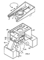
- Figure 1 depicts a perspective representation of one embodiment of the X-ray photography apparatus according to )the invention, in part exploded for the sake of illustration, and
- Figure 2 depicts in a corresponding manner an alternative embodiment.
- The X-ray apparatus includes a stationary frame, which is 5indicated in the drawing by reference numeral 1 and which, in addition to the part shown in the drawing, normally includes a vertical pole attached to it and a stand resting on the floor. The protruding part 1 shown in the drawing is, of course, in practice encased, but for the sake of illustration this casing is not shown.
- To the frame 1 there is attached using bearings a
bearing part 2, which is capable of moving in the frame linearly along a horizontal plane and supported byrails 3. The movement is produced by astepping motor 4, the shaft of which is ascrew 5 which works in conjunction with the bearingpart 2. To thebearing part 2 there is further attached rotatably with bearings a sleeve 6, which is rotated by another stepping motor 7 by transmission of a cogged belt 8. - To the sleeve 6 there is fastened by means of screws a casing-like part 9, which thus rotates together with the sleeve 6 and to which there is further attached with bearings in a manner depicted below a
support arm 10, which constitutes an essential part of the photography apparatus. - At one end of the support arm there is a
movable X-ray film 11 and at its opposite end asource 12 of X-radiation with means for limiting the beam. During the exposure thesupport arm 10 performs at least a partial rotational movement, the fulcrum moving at the same time linearly together with thebearing part 2, and the head of the patient being located between thesource 12 of X-radiation and theX-ray film 11. OThis arrangement is already so familiar to experts in the art that it is not described here in greater detail. It is also evident that, as an alternative to the linear shift of thebearing part 2, it is possible to shift the patient, i.e. the chair of the patient, correspondingly 5during the rotational movement of the support arm. - It is an essential characteristic of the present invention that a possibility is provided for moving the support arm in the direction of the arm itself, in other words in a direction parallel to the straight line connecting the )source of X-radiation and the film. In addition, a possibility is provided for tilting the support arm in such a way that the X-ray beam travels obliquely upwards or obliquely downwards. The latter adjustments are implemented as follows.
- At the lower edge of the interior sides of the casing 9 there are provided
curved guides 13, which work in conjunction with correspondingcurved guides 14 in the control part 16. At the lower edge of theside piece 23 of the control part 16 there is additionally astrip 24, and the flat middle section 22 of thesupport arm 10 can move supported by this strip. The last-mentioned movement in a direction parallel to the X-ray beam is produced by a stepping motor 19, which rotates a transverse shaft and itscogwheels 20, the cogwheels for their part working in conjunction with cogged bars 21 in the middle section 22. Respectively, of course, it is possible to use friction wheels. The control part 16 for its part is moved by a screw 18 which grips it in an articulated way and serves as the shaft of thestepping motor 17, which for its part is articulated by means of atransverse shaft 15 to the casing part 9. Themotor 17 thus affects the mutual shifting of theguides transfer motor 17 of the control part 16 has been suspended in an articulated way. - The image enlargement coefficient can be changed by moving the
support arm 10 in a direction parallel to the beam, in other words by means of the motor 19. By rotating thesupport arm 10 180 it is thus possible to allow the source of radiation to travel around either the neck or the face of the patient, and a suitable enlargement coefficient can be produced without shifting the patient. - For example, when somewhat slanted teeth are being photographed, it may be appropriate to tilt the support arm by means of the
motor 17 and thecurved rails - One alternative arrangement is shown in Figure 2. In it, the linear transfer, i.e. the transfer in a direction parallel to the plane of the X-ray beam, is produced by means of a
plate 26 attached to the sleeve 6, the edges of the plate being guided byrails 28 on the sides of the casing-like part 27. The transfer is effected by means of a motor 29, which is secured to the lower surface of theplate 26. - In this embodiment, at least the middle section of the
support arm 10 is curved in such a way that the center point of the curve, i.e. the tilting axis, is again located approximately at the level of the head of thepatient 25.Rollers 30, 31, attached by means of bearings inside thecasing 27, work in conjunction with thearch 10, the rollers working against the side, upper and lower surfaces of the arch (the last-mentioned not shown), directing the arch along its own curved line. The transfer movement is produced by means of a spindle motor 32 attached turnably to thecasing 27 by means of ashaft 33, the threadedshaft 34 of the motor engaging in amating piece 35 attached turnably to the side of the arch. - As is well known by experts in the field, the film must also be moved synchronically with the rotational movement of the support arm. The shifting of the film is also produced preferably by means of a stepping motor, although this arrangement is not shown in the drawing. As was mentioned above, stepping motors are preferably controlled electronically in a manner known per se, especially by means of a programmed or a programmable microprocessor, in which case no mechanical means such as cams or the like are required for mutual synchronization of the movements of the different parts.
Claims (8)
Applications Claiming Priority (2)
| Application Number | Priority Date | Filing Date | Title |
|---|---|---|---|
| FI840412A FI88671C (en) | 1984-02-01 | 1984-02-01 | X-ray photography device for the teeth and chin |
| FI840412 | 1984-02-01 |
Publications (3)
| Publication Number | Publication Date |
|---|---|
| EP0155072A2 true EP0155072A2 (en) | 1985-09-18 |
| EP0155072A3 EP0155072A3 (en) | 1987-05-20 |
| EP0155072B1 EP0155072B1 (en) | 1990-11-14 |
Family
ID=8518469
Family Applications (1)
| Application Number | Title | Priority Date | Filing Date |
|---|---|---|---|
| EP85300524A Expired - Lifetime EP0155072B1 (en) | 1984-02-01 | 1985-01-25 | An apparatus for x-ray photography of the area of the dentition and of the jaws |
Country Status (9)
| Country | Link |
|---|---|
| US (1) | US4683581A (en) |
| EP (1) | EP0155072B1 (en) |
| JP (1) | JPS60179045A (en) |
| AU (1) | AU570766B2 (en) |
| CA (1) | CA1252328A (en) |
| DE (1) | DE3580500D1 (en) |
| ES (1) | ES8601672A1 (en) |
| FI (1) | FI88671C (en) |
| SU (1) | SU1424721A3 (en) |
Cited By (2)
| Publication number | Priority date | Publication date | Assignee | Title |
|---|---|---|---|---|
| GB2186770A (en) * | 1986-02-04 | 1987-08-19 | Orion Yhtymae Oy | Radiography of dental, jaw and skull regions |
| EP3586751B1 (en) | 2017-02-23 | 2021-07-07 | J. Morita Manufacturing Corporation | X-ray tomography device and x-ray tomography method |
Families Citing this family (12)
| Publication number | Priority date | Publication date | Assignee | Title |
|---|---|---|---|---|
| JPS6122842A (en) * | 1984-07-10 | 1986-01-31 | 朝日レントゲン工業株式会社 | Dental jaw x-ray photographing apparatus |
| CH666803A5 (en) * | 1985-01-25 | 1988-08-31 | Hanspeter Dr Med Dent Delnon | DEVICE FOR TAKING ROENTGEN LAYER IMAGES. |
| DE3679652D1 (en) * | 1985-12-20 | 1991-07-11 | Siemens Ag | DENTAL X-RAY DIAGNOSTIC DEVICE FOR CREATING PANORAMIC LAYING FROM A PATIENT'S JAW. |
| FI73326B (en) * | 1986-01-23 | 1987-05-29 | Radiante Oy | FOERFARANDE OCH ANORDNING FOER UPPTAGNING OCH AOTERGIVNING AV BILDINFORMATION VID ROENTGENPANORAMAAVBILDNING. |
| FI98488C (en) * | 1993-01-08 | 1997-07-10 | Orion Yhtymae Oy | A method for realizing standard magnification in panoramic X-ray imaging |
| FI104943B (en) * | 1998-06-26 | 2000-05-15 | Planmeca Oy | Method, apparatus and their use in tomography imaging |
| WO2002017790A1 (en) * | 2000-08-29 | 2002-03-07 | Vladimir Ivanovich Popov | Radiographic scanning device |
| FI110822B (en) * | 2001-03-27 | 2003-03-31 | Planmeca Oy | Method and arrangement for actuating movements of X-ray equipment, in particular panoramic X-ray equipment |
| EP1408835A2 (en) | 2001-07-25 | 2004-04-21 | Dentsply International, Inc. | Real-time digital x-ray imaging apparatus |
| US7197109B2 (en) | 2002-07-25 | 2007-03-27 | Gendex Corporation | Real-time digital x-ray imaging apparatus |
| JP2004136027A (en) * | 2002-10-21 | 2004-05-13 | Univ Nihon | Image processing device |
| JP5206822B2 (en) | 2010-07-09 | 2013-06-12 | 株式会社デンソー | Semiconductor device |
Citations (2)
| Publication number | Priority date | Publication date | Assignee | Title |
|---|---|---|---|---|
| US2595260A (en) * | 1949-02-05 | 1952-05-06 | F R Machine Works | Multiplane X-ray apparatus |
| US4039837A (en) * | 1976-02-25 | 1977-08-02 | Kabushiki Kaisha Morita Seisakusho | Method of making tomogram and apparatus |
Family Cites Families (9)
| Publication number | Priority date | Publication date | Assignee | Title |
|---|---|---|---|---|
| FR2054492B1 (en) * | 1969-07-16 | 1974-06-14 | Radiologie Cie Gle | |
| DE2134122C3 (en) * | 1971-07-08 | 1984-05-30 | Siemens AG, 1000 Berlin und 8000 München | X-ray machine for skull examinations |
| FI66993C (en) * | 1976-12-10 | 1984-12-10 | Orion Yhtymae Oy | ROERELSEMEKANISM FOER EN ROENTGENSTRAOLNINGSKAELLAN OCH FILMHAOLLARE FOER PANORAMA-ROENTGENFOTOGRAFERING |
| DE2758191A1 (en) * | 1977-12-27 | 1979-06-28 | Siemens Ag | DENTAL X-RAY DIAGNOSTIC DEVICE |
| JPS551053A (en) * | 1978-06-19 | 1980-01-07 | Daido Steel Co Ltd | Electrode gripper for arc furnace |
| DE3007935A1 (en) * | 1980-03-01 | 1981-09-17 | Philips Patentverwaltung Gmbh, 2000 Hamburg | DENTAL TOMOGRAPHY UNIT |
| US4373361A (en) * | 1981-04-13 | 1983-02-15 | Thorneburg James L | Ski sock with integrally knit thickened fabric areas |
| DE3276255D1 (en) * | 1981-06-23 | 1987-06-11 | Thomson Csf | Sliding load holder with a telescopic structure and x-ray apparatus provided with such a sliding load holder |
| US4534048A (en) * | 1983-01-03 | 1985-08-06 | Pennwalt Corporation | Methods of increasing anterior layer thickness of continuous dental images obtained through rotational panoramic radiography |
-
1984
- 1984-02-01 FI FI840412A patent/FI88671C/en not_active IP Right Cessation
-
1985
- 1985-01-23 AU AU38000/85A patent/AU570766B2/en not_active Ceased
- 1985-01-25 DE DE8585300524T patent/DE3580500D1/en not_active Expired - Lifetime
- 1985-01-25 EP EP85300524A patent/EP0155072B1/en not_active Expired - Lifetime
- 1985-01-30 ES ES539981A patent/ES8601672A1/en not_active Expired
- 1985-01-31 CA CA000473329A patent/CA1252328A/en not_active Expired
- 1985-01-31 US US06/696,776 patent/US4683581A/en not_active Expired - Lifetime
- 1985-01-31 SU SU853857497A patent/SU1424721A3/en active
- 1985-01-31 JP JP60017688A patent/JPS60179045A/en active Granted
Patent Citations (2)
| Publication number | Priority date | Publication date | Assignee | Title |
|---|---|---|---|---|
| US2595260A (en) * | 1949-02-05 | 1952-05-06 | F R Machine Works | Multiplane X-ray apparatus |
| US4039837A (en) * | 1976-02-25 | 1977-08-02 | Kabushiki Kaisha Morita Seisakusho | Method of making tomogram and apparatus |
Cited By (4)
| Publication number | Priority date | Publication date | Assignee | Title |
|---|---|---|---|---|
| GB2186770A (en) * | 1986-02-04 | 1987-08-19 | Orion Yhtymae Oy | Radiography of dental, jaw and skull regions |
| AU598513B2 (en) * | 1986-02-04 | 1990-06-28 | Orion-Yhtyma Oy | Method and apparatus for radiography of the dental, jaw, and skull regions |
| GB2186770B (en) * | 1986-02-04 | 1990-07-11 | Orion Yhtymae Oy | Method and apparatus for radiography of the dental, jaw and skull regions |
| EP3586751B1 (en) | 2017-02-23 | 2021-07-07 | J. Morita Manufacturing Corporation | X-ray tomography device and x-ray tomography method |
Also Published As
| Publication number | Publication date |
|---|---|
| DE3580500D1 (en) | 1990-12-20 |
| FI840412A0 (en) | 1984-02-01 |
| EP0155072B1 (en) | 1990-11-14 |
| SU1424721A3 (en) | 1988-09-15 |
| AU570766B2 (en) | 1988-03-24 |
| FI88671C (en) | 1993-06-28 |
| US4683581A (en) | 1987-07-28 |
| JPS60179045A (en) | 1985-09-12 |
| EP0155072A3 (en) | 1987-05-20 |
| AU3800085A (en) | 1985-08-08 |
| JPH0554341B2 (en) | 1993-08-12 |
| ES539981A0 (en) | 1985-11-16 |
| CA1252328A (en) | 1989-04-11 |
| FI840412A (en) | 1985-08-02 |
| FI88671B (en) | 1993-03-15 |
| ES8601672A1 (en) | 1985-11-16 |
Similar Documents
| Publication | Publication Date | Title |
|---|---|---|
| US4683581A (en) | Apparatus for X-ray photography of the area of the dentition and of the jaws | |
| JPH0715524Y2 (en) | Dental panoramic cephalography system | |
| JPH11509461A (en) | Patient support | |
| US5506879A (en) | Planigraphic X-ray apparatus | |
| FI90197B (en) | Method and apparatus for panoramic radiography | |
| EP0151007B1 (en) | An apparatus for x-ray photography of the area of the dentition and of the jaws | |
| US4484343A (en) | Tilting table X-ray apparatus | |
| US3778049A (en) | Angiographic cradle | |
| US2789231A (en) | Appliance for radiographic representation of sections of the body | |
| EP1089661A1 (en) | Method, apparatus and their use in tomographic imaging | |
| US11931191B2 (en) | Ct imaging apparatus | |
| US5386449A (en) | Method and a device for carrying out constant enlargement in panoramic tomographic X-ray photography | |
| JPH01209047A (en) | Breast imaging apparatus | |
| US4321472A (en) | Panoramic dental X-ray machine with camera detached therefrom | |
| US5148454A (en) | Apparatus for conducting cranial X-ray tomography and radiography | |
| JPS5839687Y2 (en) | Tomographic X-ray imaging device | |
| KR20220016205A (en) | CT imaging device | |
| JPS5839693Y2 (en) | Movement mechanism of panoramic X-ray imaging device | |
| JPS61276544A (en) | Tomographic apparatus | |
| JPS60108037A (en) | Computer tomogaphic apparatus | |
| JPH04288152A (en) | X-ray tomographic camera |
Legal Events
| Date | Code | Title | Description |
|---|---|---|---|
| PUAI | Public reference made under article 153(3) epc to a published international application that has entered the european phase |
Free format text: ORIGINAL CODE: 0009012 |
|
| AK | Designated contracting states |
Designated state(s): AT BE CH DE FR GB IT LI NL SE |
|
| PUAL | Search report despatched |
Free format text: ORIGINAL CODE: 0009013 |
|
| AK | Designated contracting states |
Kind code of ref document: A3 Designated state(s): AT BE CH DE FR GB IT LI NL SE |
|
| 17P | Request for examination filed |
Effective date: 19870908 |
|
| 17Q | First examination report despatched |
Effective date: 19890615 |
|
| RBV | Designated contracting states (corrected) |
Designated state(s): DE FR GB IT NL |
|
| ITF | It: translation for a ep patent filed |
Owner name: CALVANI SALVI E VERONELLI S.R.L. |
|
| GRAA | (expected) grant |
Free format text: ORIGINAL CODE: 0009210 |
|
| AK | Designated contracting states |
Kind code of ref document: B1 Designated state(s): DE FR GB IT NL |
|
| ET | Fr: translation filed | ||
| REF | Corresponds to: |
Ref document number: 3580500 Country of ref document: DE Date of ref document: 19901220 |
|
| PLBI | Opposition filed |
Free format text: ORIGINAL CODE: 0009260 |
|
| 26 | Opposition filed |
Opponent name: INSTRUMENTARIUM CORP. IMAGING Effective date: 19910808 |
|
| NLR1 | Nl: opposition has been filed with the epo |
Opponent name: INSTRUMENTARIUM CORP. IMAGING |
|
| ITTA | It: last paid annual fee | ||
| PLBN | Opposition rejected |
Free format text: ORIGINAL CODE: 0009273 |
|
| STAA | Information on the status of an ep patent application or granted ep patent |
Free format text: STATUS: OPPOSITION REJECTED |
|
| 27O | Opposition rejected |
Effective date: 19940214 |
|
| NLR2 | Nl: decision of opposition | ||
| PGFP | Annual fee paid to national office [announced via postgrant information from national office to epo] |
Ref country code: FR Payment date: 20001229 Year of fee payment: 17 |
|
| PGFP | Annual fee paid to national office [announced via postgrant information from national office to epo] |
Ref country code: GB Payment date: 20010102 Year of fee payment: 17 |
|
| PGFP | Annual fee paid to national office [announced via postgrant information from national office to epo] |
Ref country code: NL Payment date: 20010119 Year of fee payment: 17 |
|
| REG | Reference to a national code |
Ref country code: GB Ref legal event code: IF02 |
|
| PG25 | Lapsed in a contracting state [announced via postgrant information from national office to epo] |
Ref country code: GB Free format text: LAPSE BECAUSE OF NON-PAYMENT OF DUE FEES Effective date: 20020125 |
|
| PG25 | Lapsed in a contracting state [announced via postgrant information from national office to epo] |
Ref country code: NL Free format text: LAPSE BECAUSE OF NON-PAYMENT OF DUE FEES Effective date: 20020801 |
|
| GBPC | Gb: european patent ceased through non-payment of renewal fee |
Effective date: 20020125 |
|
| PG25 | Lapsed in a contracting state [announced via postgrant information from national office to epo] |
Ref country code: FR Free format text: LAPSE BECAUSE OF NON-PAYMENT OF DUE FEES Effective date: 20020930 |
|
| NLV4 | Nl: lapsed or anulled due to non-payment of the annual fee |
Effective date: 20020801 |
|
| REG | Reference to a national code |
Ref country code: FR Ref legal event code: ST |
|
| PGFP | Annual fee paid to national office [announced via postgrant information from national office to epo] |
Ref country code: DE Payment date: 20040126 Year of fee payment: 20 |
|
| PLAB | Opposition data, opponent's data or that of the opponent's representative modified |
Free format text: ORIGINAL CODE: 0009299OPPO |