EP0116910A1 - Fiberscope - Google Patents
Fiberscope Download PDFInfo
- Publication number
- EP0116910A1 EP0116910A1 EP84101341A EP84101341A EP0116910A1 EP 0116910 A1 EP0116910 A1 EP 0116910A1 EP 84101341 A EP84101341 A EP 84101341A EP 84101341 A EP84101341 A EP 84101341A EP 0116910 A1 EP0116910 A1 EP 0116910A1
- Authority
- EP
- European Patent Office
- Prior art keywords
- fiberscope
- tube
- balloon
- tip
- flexible tube
- Prior art date
- Legal status (The legal status is an assumption and is not a legal conclusion. Google has not performed a legal analysis and makes no representation as to the accuracy of the status listed.)
- Granted
Links
Images

Classifications
-
- A—HUMAN NECESSITIES
- A61—MEDICAL OR VETERINARY SCIENCE; HYGIENE
- A61B—DIAGNOSIS; SURGERY; IDENTIFICATION
- A61B10/00—Other methods or instruments for diagnosis, e.g. instruments for taking a cell sample, for biopsy, for vaccination diagnosis; Sex determination; Ovulation-period determination; Throat striking implements
-
- A—HUMAN NECESSITIES
- A61—MEDICAL OR VETERINARY SCIENCE; HYGIENE
- A61B—DIAGNOSIS; SURGERY; IDENTIFICATION
- A61B1/00—Instruments for performing medical examinations of the interior of cavities or tubes of the body by visual or photographical inspection, e.g. endoscopes; Illuminating arrangements therefor
- A61B1/313—Instruments for performing medical examinations of the interior of cavities or tubes of the body by visual or photographical inspection, e.g. endoscopes; Illuminating arrangements therefor for introducing through surgical openings, e.g. laparoscopes
- A61B1/3137—Instruments for performing medical examinations of the interior of cavities or tubes of the body by visual or photographical inspection, e.g. endoscopes; Illuminating arrangements therefor for introducing through surgical openings, e.g. laparoscopes for examination of the interior of blood vessels
-
- A—HUMAN NECESSITIES
- A61—MEDICAL OR VETERINARY SCIENCE; HYGIENE
- A61B—DIAGNOSIS; SURGERY; IDENTIFICATION
- A61B1/00—Instruments for performing medical examinations of the interior of cavities or tubes of the body by visual or photographical inspection, e.g. endoscopes; Illuminating arrangements therefor
- A61B1/00064—Constructional details of the endoscope body
- A61B1/00071—Insertion part of the endoscope body
- A61B1/0008—Insertion part of the endoscope body characterised by distal tip features
- A61B1/00082—Balloons
-
- A—HUMAN NECESSITIES
- A61—MEDICAL OR VETERINARY SCIENCE; HYGIENE
- A61B—DIAGNOSIS; SURGERY; IDENTIFICATION
- A61B1/00—Instruments for performing medical examinations of the interior of cavities or tubes of the body by visual or photographical inspection, e.g. endoscopes; Illuminating arrangements therefor
- A61B1/00163—Optical arrangements
- A61B1/00165—Optical arrangements with light-conductive means, e.g. fibre optics
-
- A—HUMAN NECESSITIES
- A61—MEDICAL OR VETERINARY SCIENCE; HYGIENE
- A61B—DIAGNOSIS; SURGERY; IDENTIFICATION
- A61B1/00—Instruments for performing medical examinations of the interior of cavities or tubes of the body by visual or photographical inspection, e.g. endoscopes; Illuminating arrangements therefor
- A61B1/012—Instruments for performing medical examinations of the interior of cavities or tubes of the body by visual or photographical inspection, e.g. endoscopes; Illuminating arrangements therefor characterised by internal passages or accessories therefor
- A61B1/015—Control of fluid supply or evacuation
Definitions
- the present invention relates to a fiberscope. More particularly, the invention relates to a fiberscope which is adapted to be inserted into a bodily passage, such as a blood vessel or the like, through which an opaque fluid, such as blood, passes to observe the interior of the passage.
- a bodily passage such as a blood vessel or the like
- a conventional fiberscope of the same general type to which the invention pertains includes an illuminating light carrying optical fiber 7 passing through a flexible tube 1 to direct light from a light source 3 to a blood vessel wall 5, an image light receiving optical fiber 11 for directing light reflected from an image of the blood vessel wall and received through an optical system at the end thereof to an eyepiece assembly 9, and a liquid guiding passage 17 for guiding a transparent flushing liquid such as a normal saline solution from a syringe 15 to' the tip of the fiberscope to form a transparent region between the blood vessel wall 5 and the tip of the fiberscope.
- Reference numeral 19 designates a branching mount.
- the flushing liquid which forms the transparent region should be supplied at a flow rate Q F at least equal to the flow rate Q B of blood, that is, about 50 cm 3 /sec.
- a flow rate Q F at least equal to the flow rate Q B of blood, that is, about 50 cm 3 /sec.
- the required volume of the flushing liquid is 25 cm 3 .
- injection of such a large quantity of normal saline solution into the blood vessel in such a period of time may create a shock force which damages the vessel, while further the high pressure required to inject the solution might possibly force dissolved gas out of the solution, which is of course dangerous.
- the initial velocity of the saline solution jetted from a flushing tube of an inner diameter of 3 mm is about 7 m/sec. This causes a strong shock to the blood vessel.
- the liquid guide passage must have a large cross section. This causes the overall diameter of the fiberscope tube to be large, resulting in disadvantages in that difficulties are then encountered in inserting the tube into the blood vessel to be examined.
- a fiberscope according to the invention which is adapted to be inserted into a bodily passage through which an opaque liquid passes for observing the interior of the passage, includes a light carrying optical fiber passing through a flexible tube to direct light from a light source to the object to be observed, an image receiving optical fiber for conveying an image of the object to viewing means, and a liquid guide passage for guiding a transparent flushing liquid and to jet the latter from the tip of the tube.
- an expandible balloon is provided rearwardly of the tip of the tube around the side wall of the tube, and a fluid passage for inflating the balloon is provided in the tube in communication with the interior of the balloon to thereby inflate the balloon when an observation is to be made to temporarily slow the flow of the opaque fluid, thereby to minimize the flow rate of the flushing liquid required for a visual field formation.
- Fig. 3 through 6 show an embodiment of the invention applied to an intravascular observing fiberscope, similar to the case of Fig. 1.
- like reference numerals are used to designate like components in Fig. 1.
- an inflatable balloon 21 (see Fig. 4) is provided rearwardly of the tip of the tube from which a flow 13 of flushing fluid is jetted and around the side of the tube, and a fluid passage 27 is formed in the tube 1 to supply fluid for inflating the balloon.
- the inflating flush may, for instance, be carbon dioxide or normal saline supplied from a syringe 23 through a tube 25, 25' (see Fig. 5).
- the balloon 21 is mounted around the tube by fastening front and rear ends 21a and 21b of a cylindrically shaped elastic element with thread, heat- shrinkable tubing, or adhesive to form a fluid-tight engagement with the tube 1.
- Polyurethane, natural rubber, silicon rubber and the like can be employed as the material of the balloon 21.
- the interior of the tube 1 can be divided by a plurality of longitudinally extending partition walls 29 into a plurality of passages, as shown in Fig. 6, one of the latter being an inflating fluid passage 25" for balloon inflation.
- the side wall of the tube at the balloon mounting portion is provided with a hole 27 in communication with the inflating passage.
- the inflating passage is blocked forwardly of the hole 27 with a filler- 31, such as a resin or the like.
- the other passages into which the tube is divided by the partition walls 29 are available as passages for the light carrying optical fiber 7, the light receiving optical fiber 11, and the flushing liquid.
- the fluid for inflating the balloon is supplied from the syringe 23- to the balloon when the interior of the blood vessel is to be observed, to thus expand the balloon to a size such that the blood flow downstream of the balloon 21 is momentarily reduced to a flow rate q B less than the flow rate Q B upstream thereof.
- the flushing liquid 13 is supplied from the syringe 15 at a flow rate q F required for providing a clear visual field. Since the blood flow rate q B is substantially reduced from Q B , the flow rate q F can accordingly be made substantially less than Q F .
- the total volume of the flushing liquid required is less than in the conventional arrangement, thereby reducing the shock force acting on the inner walls of the blood vessel and the surrounding tissue.
- the outer diameter of the tube 1 is also reduced, making possible easy insertion into blood vessels. If the balloon 21 is mounted * in the proximity of the tip of the tube 1, the balloon 21 can be made to expand longitudinally, thus providing support for the tip of the tube centrally of the interior of the blood vessel.
- the required flushing liquid flow rate for forming a clear visual field is lowered to therefore minimize the total volume of the flushing liquid needed and the pressure at which the liquid is supplied.
- a fiberscope is obtained having greatly lessened ill effects on the body.
Abstract
Description
- The present invention relates to a fiberscope. More particularly, the invention relates to a fiberscope which is adapted to be inserted into a bodily passage, such as a blood vessel or the like, through which an opaque fluid, such as blood, passes to observe the interior of the passage.
- A conventional fiberscope of the same general type to which the invention pertains, as shown in Figs. 1 and 2, includes an illuminating light carrying
optical fiber 7 passing through aflexible tube 1 to direct light from alight source 3 to ablood vessel wall 5, an image light receivingoptical fiber 11 for directing light reflected from an image of the blood vessel wall and received through an optical system at the end thereof to aneyepiece assembly 9, and a liquid guidingpassage 17 for guiding a transparent flushing liquid such as a normal saline solution from asyringe 15 to' the tip of the fiberscope to form a transparent region between theblood vessel wall 5 and the tip of the fiberscope.Reference numeral 19 designates a branching mount. - The flushing liquid which forms the transparent region should be supplied at a flow rate QF at least equal to the flow rate QB of blood, that is, about 50 cm3/sec. For example, where a blood vessel has an inner diameter of 10 mm, the blood flows at a speed of 64 cm/sec. In this instance, if it is desired to obtain a clear visual field for 0.5 sec., the required volume of the flushing liquid is 25 cm3. However, injection of such a large quantity of normal saline solution into the blood vessel in such a period of time may create a shock force which damages the vessel, while further the high pressure required to inject the solution might possibly force dissolved gas out of the solution, which is of course dangerous. For example, the initial velocity of the saline solution jetted from a flushing tube of an inner diameter of 3 mm is about 7 m/sec. This causes a strong shock to the blood vessel. Moreover, if a large quantity of normal saline solution is to be injected, the liquid guide passage must have a large cross section. This causes the overall diameter of the fiberscope tube to be large, resulting in disadvantages in that difficulties are then encountered in inserting the tube into the blood vessel to be examined.
- It is a primary object of the invention to remedy the shortcomings noted above. To this end, a fiberscope according to the invention, which is adapted to be inserted into a bodily passage through which an opaque liquid passes for observing the interior of the passage, includes a light carrying optical fiber passing through a flexible tube to direct light from a light source to the object to be observed, an image receiving optical fiber for conveying an image of the object to viewing means, and a liquid guide passage for guiding a transparent flushing liquid and to jet the latter from the tip of the tube. In accordance with an important aspect of the invention, an expandible balloon is provided rearwardly of the tip of the tube around the side wall of the tube, and a fluid passage for inflating the balloon is provided in the tube in communication with the interior of the balloon to thereby inflate the balloon when an observation is to be made to temporarily slow the flow of the opaque fluid, thereby to minimize the flow rate of the flushing liquid required for a visual field formation.
-
- Fig. 1 is a perspective view showing a conventional fiberscope;
- Fig. 2 is a cross-sectional view of a portion of the fiberscope shown in Fig. 1 inserted into a blood vessel;
- Fig. 3 is a view similar to Fig. 1 but showing a fiberscope according to the present invention;
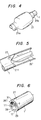
- Fig. 4 is a perspective view showing a mounting structure of a balloon; and
- Figs. 5 and 6 are perspective views showing a configuration of a fluid passage used for inflating the balloon.
- Details of the invention will be hereinafter explained with reference to the accompanying drawings in which a preferred embodiment of the invention is shown.
- Fig. 3 through 6 show an embodiment of the invention applied to an intravascular observing fiberscope, similar to the case of Fig. 1. In-these figures, like reference numerals are used to designate like components in Fig. 1.
- In accordance with the invention, an inflatable balloon 21 (see Fig. 4) is provided rearwardly of the tip of the tube from which a
flow 13 of flushing fluid is jetted and around the side of the tube, and afluid passage 27 is formed in thetube 1 to supply fluid for inflating the balloon. The inflating flush may, for instance, be carbon dioxide or normal saline supplied from asyringe 23 through atube 25, 25' (see Fig. 5). Theballoon 21 is mounted around the tube by fastening front andrear ends tube 1. Polyurethane, natural rubber, silicon rubber and the like can be employed as the material of theballoon 21. - As an alternative to the
tube 25, 25', the interior of thetube 1 can be divided by a plurality of longitudinally extendingpartition walls 29 into a plurality of passages, as shown in Fig. 6, one of the latter being aninflating fluid passage 25" for balloon inflation. In that case, the side wall of the tube at the balloon mounting portion is provided with ahole 27 in communication with the inflating passage. The inflating passage is blocked forwardly of thehole 27 with a filler- 31, such as a resin or the like. The other passages into which the tube is divided by thepartition walls 29 are available as passages for the light carryingoptical fiber 7, the light receivingoptical fiber 11, and the flushing liquid. - In the arrangement described above, the fluid for inflating the balloon is supplied from the syringe 23- to the balloon when the interior of the blood vessel is to be observed, to thus expand the balloon to a size such that the blood flow downstream of the
balloon 21 is momentarily reduced to a flow rate qB less than the flow rate QB upstream thereof. When the balloon has been inflated, the flushingliquid 13 is supplied from thesyringe 15 at a flow rate qF required for providing a clear visual field. Since the blood flow rate qB is substantially reduced from QB, the flow rate qF can accordingly be made substantially less than QF. Hence, the total volume of the flushing liquid required is less than in the conventional arrangement, thereby reducing the shock force acting on the inner walls of the blood vessel and the surrounding tissue. The outer diameter of thetube 1 is also reduced, making possible easy insertion into blood vessels. If theballoon 21 is mounted * in the proximity of the tip of thetube 1, theballoon 21 can be made to expand longitudinally, thus providing support for the tip of the tube centrally of the interior of the blood vessel. - As set forth hereinbefore, according to the invention, the required flushing liquid flow rate for forming a clear visual field is lowered to therefore minimize the total volume of the flushing liquid needed and the pressure at which the liquid is supplied. Thus, a fiberscope is obtained having greatly lessened ill effects on the body.
- Although preferred embodiments have been described with reference to a fiberscope used for examining blood vessels, the invention is not limited thereto and is generally applicable to any fiberscope adapted to be inserted into a passage through which an opaque liquid or gas passes for observing the interior of the passage.
Claims (5)
Applications Claiming Priority (2)
| Application Number | Priority Date | Filing Date | Title |
|---|---|---|---|
| JP27875/83 | 1983-02-22 | ||
| JP58027875A JPS59155231A (en) | 1983-02-22 | 1983-02-22 | Fiberscope |
Publications (2)
| Publication Number | Publication Date |
|---|---|
| EP0116910A1 true EP0116910A1 (en) | 1984-08-29 |
| EP0116910B1 EP0116910B1 (en) | 1987-06-10 |
Family
ID=12233062
Family Applications (1)
| Application Number | Title | Priority Date | Filing Date |
|---|---|---|---|
| EP84101341A Expired EP0116910B1 (en) | 1983-02-22 | 1984-02-09 | Fiberscope |
Country Status (7)
| Country | Link |
|---|---|
| US (1) | US4576145A (en) |
| EP (1) | EP0116910B1 (en) |
| JP (1) | JPS59155231A (en) |
| KR (1) | KR860001795B1 (en) |
| AU (1) | AU559599B2 (en) |
| CA (1) | CA1223493A (en) |
| DE (1) | DE3464117D1 (en) |
Cited By (1)
| Publication number | Priority date | Publication date | Assignee | Title |
|---|---|---|---|---|
| US4772093A (en) * | 1985-12-12 | 1988-09-20 | Microvasive, Inc. | Fiber-optic image-carrying device |
Families Citing this family (32)
| Publication number | Priority date | Publication date | Assignee | Title |
|---|---|---|---|---|
| US4756306A (en) * | 1984-03-20 | 1988-07-12 | Safeguard Technologies, Inc. | Therapeutic belt |
| JPS6185916A (en) * | 1984-10-04 | 1986-05-01 | 住友電気工業株式会社 | Endoscope catheter |
| EP0177124A3 (en) * | 1984-07-18 | 1987-01-21 | Sumitomo Electric Industries Limited | Catheter |
| JP2602212B2 (en) * | 1985-09-30 | 1997-04-23 | オリンパス光学工業株式会社 | Multi-lumen tube endoscope |
| JPS62113125A (en) * | 1985-11-13 | 1987-05-25 | Olympus Optical Co Ltd | Endoscope |
| JPS62266025A (en) * | 1986-05-10 | 1987-11-18 | 株式会社 メデイカルサイエンス | Blood vessel endoscopic video system |
| JPS633834A (en) * | 1986-06-24 | 1988-01-08 | 株式会社 メデイカルサイエンス | Blood vessel endoscopic video system |
| JPS63143024A (en) * | 1986-12-05 | 1988-06-15 | 三菱電線工業株式会社 | Catheter type fiberscope |
| US4998972A (en) * | 1988-04-28 | 1991-03-12 | Thomas J. Fogarty | Real time angioscopy imaging system |
| US4878893A (en) * | 1988-04-28 | 1989-11-07 | Thomas J. Fogarty | Angioscope with flush solution deflector shield |
| DE3916288C2 (en) * | 1988-05-20 | 1993-10-28 | Wolfgang Dr Vilmar | Uretero-renoscope |
| WO1989012479A1 (en) * | 1988-06-16 | 1989-12-28 | Optimed Technologies, Inc. | Angioplasty catheter with integral fiber optic |
| US5116317A (en) * | 1988-06-16 | 1992-05-26 | Optimed Technologies, Inc. | Angioplasty catheter with integral fiber optic assembly |
| JPH0736641Y2 (en) * | 1988-10-24 | 1995-08-23 | オリンパス光学工業株式会社 | Endoscope |
| US5167220A (en) * | 1990-08-09 | 1992-12-01 | Brown Cathy K | Systems and methods for maintaining a clear visual field during endoscopic procedures |
| JPH04215285A (en) * | 1991-03-07 | 1992-08-06 | Toshiba Lighting & Technol Corp | Heater |
| US5156590A (en) * | 1991-06-24 | 1992-10-20 | Wolfgang Vilmar | Uretero-renoscope with catheter body having plural partitioned inner conduits |
| US5299560A (en) * | 1992-06-18 | 1994-04-05 | Olympus Optical Co., Ltd. | Endoscope in which a bend remaining in the insertion portion upon removal from storage is reduced |
| US5450840A (en) * | 1993-09-17 | 1995-09-19 | Kozdas; Anthony B. | Stove-top guard |
| CA2223219A1 (en) | 1995-06-07 | 1999-05-19 | Frank Louw | Side branch occlusion catheter device having integrated endoscope for performing endoscopically visualized occlusion of the side branches of an anatomical passageway |
| US5857961A (en) * | 1995-06-07 | 1999-01-12 | Clarus Medical Systems, Inc. | Surgical instrument for use with a viewing system |
| US5810790A (en) * | 1996-11-19 | 1998-09-22 | Ebling; Wendell V. | Catheter with viewing system and port connector |
| US6171251B1 (en) * | 1998-07-14 | 2001-01-09 | Eclipse Surgical Technologies, Inc. | Method and apparatus for optimizing direct vessel implants for myocardial revascularization |
| US6692430B2 (en) | 2000-04-10 | 2004-02-17 | C2Cure Inc. | Intra vascular imaging apparatus |
| WO2004012805A2 (en) * | 2002-08-05 | 2004-02-12 | Miravant Medical Technologies | Light delivery catheter |
| EP1526801A2 (en) * | 2002-08-05 | 2005-05-04 | Miravant Medical Technologies Inc. | Catheter for diagnosis and treatment of diseased vessels |
| WO2006037001A1 (en) * | 2004-09-24 | 2006-04-06 | Lightlab Imaging, Inc. | Fluid occluding devices and methods |
| US9149176B2 (en) | 2012-09-13 | 2015-10-06 | Emmy Medical, Llc | 4-way cystoscopy catheter |
| US10905452B1 (en) | 2015-04-19 | 2021-02-02 | Octavio Silva | Vertebra pick device |
| EP3644851A4 (en) | 2017-06-30 | 2021-06-09 | Enlightenvue LLC | Endoscopy systems and methods of use thereof |
| USD908865S1 (en) | 2018-08-17 | 2021-01-26 | Emmy Medical, Llc | Catheter |
| US10687698B2 (en) * | 2018-09-12 | 2020-06-23 | Enlightenvue Llc | Direct endoluminal- and/or endovascular-illumination systems and methods of use thereof |
Citations (7)
| Publication number | Priority date | Publication date | Assignee | Title |
|---|---|---|---|---|
| US3057345A (en) * | 1960-05-16 | 1962-10-09 | Bausch & Lomb | Duodenoscope |
| FR1466248A (en) * | 1965-02-22 | 1967-01-20 | Intracavitary treatment instrument | |
| FR2278305A1 (en) * | 1974-07-18 | 1976-02-13 | Fuji Photo Optical Co Ltd | ENDOSCOPE |
| US4041936A (en) * | 1975-04-23 | 1977-08-16 | Medical Engineering Corporation | Bronchoscopy tube |
| EP0066185A1 (en) * | 1981-05-20 | 1982-12-08 | Olympus Optical Co., Ltd. | Ultrasonic diagnosis device |
| DE3131652A1 (en) * | 1981-08-11 | 1983-02-24 | Christian Prof. Dr.med. 2400 Lübeck Krüger | Instrument for the collection of bile and pancreatic secretion |
| WO1983003188A1 (en) * | 1982-03-11 | 1983-09-29 | Laserscope Inc | Endoscopic device |
Family Cites Families (2)
| Publication number | Priority date | Publication date | Assignee | Title |
|---|---|---|---|---|
| US4448188A (en) * | 1982-02-18 | 1984-05-15 | Laserscope, Inc. | Method for providing an oxygen bearing liquid to a blood vessel for the performance of a medical procedure |
| US4445892A (en) * | 1982-05-06 | 1984-05-01 | Laserscope, Inc. | Dual balloon catheter device |
-
1983
- 1983-02-22 JP JP58027875A patent/JPS59155231A/en active Pending
- 1983-12-26 KR KR1019830006172A patent/KR860001795B1/en not_active IP Right Cessation
-
1984
- 1984-02-09 EP EP84101341A patent/EP0116910B1/en not_active Expired
- 1984-02-09 DE DE8484101341T patent/DE3464117D1/en not_active Expired
- 1984-02-22 CA CA000448042A patent/CA1223493A/en not_active Expired
- 1984-02-22 AU AU24817/84A patent/AU559599B2/en not_active Ceased
- 1984-02-22 US US06/582,517 patent/US4576145A/en not_active Expired - Fee Related
Patent Citations (7)
| Publication number | Priority date | Publication date | Assignee | Title |
|---|---|---|---|---|
| US3057345A (en) * | 1960-05-16 | 1962-10-09 | Bausch & Lomb | Duodenoscope |
| FR1466248A (en) * | 1965-02-22 | 1967-01-20 | Intracavitary treatment instrument | |
| FR2278305A1 (en) * | 1974-07-18 | 1976-02-13 | Fuji Photo Optical Co Ltd | ENDOSCOPE |
| US4041936A (en) * | 1975-04-23 | 1977-08-16 | Medical Engineering Corporation | Bronchoscopy tube |
| EP0066185A1 (en) * | 1981-05-20 | 1982-12-08 | Olympus Optical Co., Ltd. | Ultrasonic diagnosis device |
| DE3131652A1 (en) * | 1981-08-11 | 1983-02-24 | Christian Prof. Dr.med. 2400 Lübeck Krüger | Instrument for the collection of bile and pancreatic secretion |
| WO1983003188A1 (en) * | 1982-03-11 | 1983-09-29 | Laserscope Inc | Endoscopic device |
Cited By (1)
| Publication number | Priority date | Publication date | Assignee | Title |
|---|---|---|---|---|
| US4772093A (en) * | 1985-12-12 | 1988-09-20 | Microvasive, Inc. | Fiber-optic image-carrying device |
Also Published As
| Publication number | Publication date |
|---|---|
| US4576145A (en) | 1986-03-18 |
| AU2481784A (en) | 1984-08-30 |
| KR860001795B1 (en) | 1986-10-23 |
| JPS59155231A (en) | 1984-09-04 |
| AU559599B2 (en) | 1987-03-12 |
| EP0116910B1 (en) | 1987-06-10 |
| DE3464117D1 (en) | 1987-07-16 |
| CA1223493A (en) | 1987-06-30 |
| KR840008121A (en) | 1984-12-13 |
Similar Documents
| Publication | Publication Date | Title |
|---|---|---|
| US4576145A (en) | Fiberscope | |
| EP0112148B1 (en) | Endoscope | |
| US4619247A (en) | Catheter | |
| US4569335A (en) | Fiberscope | |
| US5090959A (en) | Imaging balloon dilatation catheter | |
| EP0402467A1 (en) | Catheter tube and endoscope | |
| EP0318918B2 (en) | Balloon cathether | |
| EP0282143B1 (en) | Catheter and guidewire exchange system | |
| EP0369012A1 (en) | Catheter tube | |
| DE69316601T2 (en) | Angioplasty perfusion catheter | |
| KR870000306B1 (en) | Fiberscopr | |
| EP0177124A2 (en) | Catheter | |
| JPH06296695A (en) | Catheter tube and endoscope | |
| JPH0661365B2 (en) | Catel tube | |
| EP0122089B1 (en) | Endoscope | |
| EP0386236A1 (en) | Catheter tube | |
| AU611894B2 (en) | Imaging balloon dilatation catheter | |
| JPH01104238A (en) | Catheter tube | |
| EP0119614B2 (en) | Fiberscope | |
| KR870002097B1 (en) | Endoscope catheter | |
| JPH01274772A (en) | Balloon catheter device | |
| JPS61293416A (en) | Catheter type fiberscope | |
| CA1240304A (en) | Endoscope | |
| KR870001167Y1 (en) | Device for fiber scope | |
| JPH0217292A (en) | Flexible pipe having branch portion |
Legal Events
| Date | Code | Title | Description |
|---|---|---|---|
| PUAI | Public reference made under article 153(3) epc to a published international application that has entered the european phase |
Free format text: ORIGINAL CODE: 0009012 |
|
| AK | Designated contracting states |
Designated state(s): DE FR GB IT NL SE |
|
| 17P | Request for examination filed |
Effective date: 19841016 |
|
| ITF | It: translation for a ep patent filed |
Owner name: SOCIETA' ITALIANA BREVETTI S.P.A. |
|
| GRAA | (expected) grant |
Free format text: ORIGINAL CODE: 0009210 |
|
| AK | Designated contracting states |
Kind code of ref document: B1 Designated state(s): DE FR GB IT NL SE |
|
| REF | Corresponds to: |
Ref document number: 3464117 Country of ref document: DE Date of ref document: 19870716 |
|
| ET | Fr: translation filed | ||
| PLBI | Opposition filed |
Free format text: ORIGINAL CODE: 0009260 |
|
| 26 | Opposition filed |
Opponent name: OLYMPUS OPTICAL COMPANY LIMITED Effective date: 19880229 |
|
| NLR1 | Nl: opposition has been filed with the epo |
Opponent name: OLYMPUS OPTICAL COMPANY LIMITED |
|
| PG25 | Lapsed in a contracting state [announced via postgrant information from national office to epo] |
Ref country code: SE Effective date: 19890210 |
|
| RDAG | Patent revoked |
Free format text: ORIGINAL CODE: 0009271 |
|
| STAA | Information on the status of an ep patent application or granted ep patent |
Free format text: STATUS: PATENT REVOKED |
|
| 27W | Patent revoked |
Effective date: 19890407 |
|
| GBPR | Gb: patent revoked under art. 102 of the ep convention designating the uk as contracting state | ||
| NLR2 | Nl: decision of opposition | ||
| EUG | Se: european patent has lapsed |
Ref document number: 84101341.0 Effective date: 19900118 |