EP0103742A1 - Angulating lateral fluoroscopic suspension - Google Patents
Angulating lateral fluoroscopic suspension Download PDFInfo
- Publication number
- EP0103742A1 EP0103742A1 EP83108033A EP83108033A EP0103742A1 EP 0103742 A1 EP0103742 A1 EP 0103742A1 EP 83108033 A EP83108033 A EP 83108033A EP 83108033 A EP83108033 A EP 83108033A EP 0103742 A1 EP0103742 A1 EP 0103742A1
- Authority
- EP
- European Patent Office
- Prior art keywords
- detector
- ray
- source
- ray source
- carriage
- Prior art date
- Legal status (The legal status is an assumption and is not a legal conclusion. Google has not performed a legal analysis and makes no representation as to the accuracy of the status listed.)
- Granted
Links
Images


Classifications
-
- A—HUMAN NECESSITIES
- A61—MEDICAL OR VETERINARY SCIENCE; HYGIENE
- A61B—DIAGNOSIS; SURGERY; IDENTIFICATION
- A61B6/00—Apparatus for radiation diagnosis, e.g. combined with radiation therapy equipment
- A61B6/44—Constructional features of apparatus for radiation diagnosis
- A61B6/4429—Constructional features of apparatus for radiation diagnosis related to the mounting of source units and detector units
- A61B6/4464—Constructional features of apparatus for radiation diagnosis related to the mounting of source units and detector units the source unit or the detector unit being mounted to ceiling
Definitions
- This invention relates to medical diagnostic x-ray apparatus, particularly apparatus for performing angiography.
- an x-ray source hung from the ceiling is positioned on one side of the patient and a freestanding x-ray detection device is positioned on the other side of the patient.
- the freestanding detector and its associated electrical cables prevent the physician from moving freely around the patient and can also interfere with the source or detector for taking postero-anterior views.
- Another deficiency of this apparatus is that the sourcs and detector for lateral views must be aligned manually.
- FIG. 12 A second approach is shown in Figures 12 and 13, illustrating two prior art devices.
- a single structural member 20 carries an x-ray source 22 and an electronic image intensifier 24 at its respective ends.
- Member 20 is supported by a brace 26 pivotally mounted to an overhead support 28 for rotating the pattern of radiation passing from source 22 to detector 24 about a vertical axis without disturbing the relative alignment of source and detector.
- source 22 and detector 24 are rigidly mounted to the respective ends of a rigid C-shaped member 30 received in a guide 32, which again is pivotally mounted to an overhead support 34.
- member 30 can be rotated as before, or can be driven in either direction through guide 32 to rotate the pattern of x-rays passing between source 22 and detector 24 about the longitudinal axis of a patient.
- an x-ray source is supported by a ceiling mounted carriage and telescoping hanger which permit the source to translate longitudinally, laterally, and vertically and to independently pivot about vertical and horizontal axes.
- An electronic image intensifier or other detector is supported in similar fashion by an independent carriage and telescoping hanger.
- the vertical positioning means for the respective hangers are linked when the source and detector are ccupled to the bridge, so raising the source lowers the image intensifier, and vice versa.
- a mechanical linkage for moving the source and detector apart or together is coupled with the vertical positioning means so that, whether the central ray passing between the source and detector is disposed horizontally or not, the source and detector are always aimed at and diametrically opposed about an isocenter within the anatomy of interest.
- the pivoting of the. source and detector about their horizontal longitudinal axes is correlated with the vertical positions of the source and detector on their hangers by electronic position sensing means which transmit signals indicating the relative elevation and pivotal positions of the source and detector.
- the source and detector are separable and can be retracted to the ceiling for compact storage when separated, and yet are mechanically linked when coupled to the bridge for tilting the central ray about vertical or longitudinal axes, permitting a wide selection of possible examination angles.
- the amount of equipment surrounding the patient is minimized, so access to the patient is maximized.
- patient 34 is supported on an examination table 36 which is cantilevered with respect to its base 38 to permit the equipment to be positioned at various points with respect to the patient.
- An L-U arm x-ray apparatus 40 is supported by the floor of the room, and in this arrangement can be used for postero-anterior examination of the patient. A further description of apparatus 40 can be found in the patent application previously incorporated by reference.
- the illustrated examination room includes an overhead support 28, which in the illustrated embodiment is its ceiling.
- An x-ray source 22 and an x-ray detector 24 are respectively supported by telescoping hangers 42, 44 having their respective upper ends 46, 48 secured to an x-ray source carriage 50 and x-ray detector carriage 52.
- the lower ends 54 and 56 of hangers 42 and 44 pivotally receive x-ray source 22 and image intensifier 24 so the latter elements can respectively rotate about an axis 58 (which is parallel to the longitudinal axis through patient 34 and passes through the focal spot of x-ray source 22) and an axis 60 which is parallel to axis 58.
- Central ray 62 of the pattern of x-rays emitted from source 22 is aimed through an.isocenter 64, as is the longitudinal axis 66 of image intensifier 24 (about which the x-ray pattern received and acted upon by image intensifier 24 is disposed).
- Source 22 and image intensifier 24 are supported adjacent to the respective lateral sides of patient 34.
- Carriage 50 is pivotally mounted to a roller truck 68 which is captured by parallel arms 70 and 72 of a lateral track member 74 to permit lateral travel of carriage 50 and rotation of the carriage about a vertical axis.
- Lateral track member 74 is suspended from a pair of roller trucks such as 76 which travel on parallel, longitudinally disposed tracks such as 78 mounted to overhead support 28 for permitting track member 74, and thus roller truck 68 and carriage 50, to travel longitudinally.
- This system provides direct support for x-ray source 22, and since hanger 42 is substantially vertical it has substantially no bending moment due to gravity.
- Carriage 52 similarly is pivotally suspended from roller truck 80, lateral track member 82, and roller trucks secured to member 82 for traveling on tracks 84 and 86 mounted to overhead support 28.
- each coupling means includes male and female mem- bars which are coupled as shown in Figure 1 to locate the carriages and uncoupled when the carriages are to be separated.
- the x-ray source can also be used independently of the image intensifier when uncoupled.
- L-U arm 40 can be pivoted 90 de- qrees about its floor pivot, so x-ray source 22 can be aimed at a auxiliary detector mounted to arm 40 (as disclosed in the previously incorporated patent application).
- Electric power and control cable bundles 94 and 96 containing conductors for providing electric power to x-ray source 22 and detector 24 and for operating the invention, are routed from source 22 and detector 24 to the respective carriages 50 and 52, and from there in helical coils supported by slides 98 carried in tracks such as 86 to a remote connection point (not shown).
- Figures 2 and 3 show several geometric relationships which are maintained by the illustrated embodiment.
- B is the distance from pivot axis 58 of x-ray source 22.to isocenter 64;
- C is the distance from pivot.
- D is the horizontal component of B and lies along a lateral axis 120 through isocenter 64;
- E is the hcrizontal component of C and also lies on axis 120;
- F is the vertical component of B;
- G is the vertical component of C;
- h is the angle between B and D; and
- i is the angle between C and E.
- Isocenter 64 is always stationary.
- B and C are always equal, and do not change for any position of the apparatus.
- F and h are respectively equal to G and i, and they all vary between zero (as in Figure 3) and a positive value (as in Figure 2).
- source 22 and image intensifier 24 are always diametrically opposed through isocenter 64 when coupled by bridge 88, and the source to image distance remains constant for any value of h and i.
- Central ray 62 and longitudinal axis 66 are always directed through isocenter 64 and are collinear.
- the entire assembly is rotatable as a rigid unit about a vertical axis 122 through isocenter 64.
- source 22 and detector 24 are mechanically linked by bridge 88, carriages 50 and 52, and hangers 42 and 44 so raising either source 22 or detector 24 lowers the other by an equal amount.
- carriages 50 and 52 are translated toward bridge 88 when F and G are increased and away from bridge 88 when F and G are decreased.
- microprocessor controlled servomechanisms aim source 22 and detector 24 toward isocenter 64 by varying h and i. The details of these mechanisms are shown in Figures 4-11.
- image intensifier 24 can translate along its longitudinal axis 66 with respect to hanger 44 to vary the isocenter to image distance without disturbing the foregoing relationships. This additional capability allows the magnification of the image to be varied without changing the other relationships just described.
- bridge 88 comprises a cross shaped horizontally disposed housing 130 mounted to overhead support 28 (Figure 1) for pivoting about vertical axis 122 (which passes through isocenter 64).
- Housing 130 supports coaxial splined shafts 132 and 134.
- the inboard end 136 of shaft 132 is carried by ball bearings 138 and 140 mounted to a truck 142 having rollers such as 144, 146, 148, and 150 which permit slight vertical translation of truck 142 within housing 130.
- the outboard end of shaft 132 is a probe 152 for being received in the bore 154 of a tubular member 156.
- Member 156 is supported partially within x-ray source carriage 50 by rotation and thrust bearings such as 158,160.
- a first coupling member 164 here a male member, is splined to and slidable along shaft 132.
- Second coupling member 166 is a female member secured to member 156 to receive first coupling member 164.
- Second coupling member 166 includes a dog 168 for being received in a bore 170 in first coupling member 164 so when the coupling members are coupled they rotate together.
- Coupling members 164 and 166 are seated together when coupled by a ball detent mechanism.
- First coupling member 164 is linked to a slide 172-which is slidably carried on splined shaft.132.
- Tubular member 156 includes a coaxial bevel gear 174 that meshes with a bevel gear 176 secured to a shaft 178 to which a power take-off cable drum 180 is fixed.
- the cable drum shaft is rotatably secured to fixed members 182 and 184 of carriage 50 by thrust and rotation bearings.
- a counterpoise drum 185 is also mounted to carriage 50.
- a flat spiral torsion spring (not shown) has its respective ends secured to drum 185 and its supports for exerting a counterclockwise (as seen in Figure 8) torque on drum 185.
- a cable 186 is wound on counterpoise drum 185, reeved about power take-off drum 180 and about an idler pulley 188, and has a vertical run 189 best seen in Figure 8. The lower end 190 of run 189 is anchored to the lower arm of hanger 42. Winding cable 186 onto drum 185 by turning drum 180 with motor 303 of the coupling drive raises source 22 and collapses hanger 42, while rotating drum 180 in the other direction extends hanger 42 and thereby lowers source 22.
- An encoder 192 is driven by an encoder cable 194 which is wound about another drum (not shown) fixed and coaxial with respect to power take-off drum 180. Cable 194 is run through direction changing block 196, and run vertically downward to an anchor 198 fixed to the lower arm of hanger 42. Encoder 192 is thus enabled to transmit a signal corresponding to the vertical position of source 22.
- a chain drive is provided to couple splined shafts 132 and 134 so they will rotate in the same direction at the same speed.
- sprockets 250 and 252 are keyed to the inboard ends of splined shafts 132 and 134
- sprockets 254 and 256 are keyed to a shaft 258 secured to bridge 38 for rotation
- chain tension adjusting sprockets 260 and 262 are rotatably and slidably carried on bridge 88.
- a first endless chain 264 trained about sprockets 250 and 254 and under sprocket 260, transmits the rotation of shaft 134 to shaft 258 (and vice versa), and an identical chain 266 transmits the rotation of shaft 132 to shaft 258 (and vice versa).
- cable 186 is wound by drum 180 at the same rate that cable 220 is unwound by drum 218, and vice versa.
- the vertical travel of source 22 is thus equal and opposite to the vertical travel of image intensifier 24 when the assembly is coupled together as shown in the Figures.
- a guide 270 is disposed perpendicularly to shafts 132 and 134 and is secured to bridge 88 by fasteners such as 272.
- a slide 276 is slidably carried on guide 270, and link arms 278 and 280 are each secured at one end by a pivct pin 282 to slide 276.
- the other ends of link arms 278 and 280 are secured by pivots 284 to the outer races of rotation bearings such as 286 carried on the respective slides such aa 172.
- Slide 276 is driven by an endless drive chain 288 having its respective ends reeved about a sprocket 290 keyed to shaft 258 and a sprocket 292 rotatably carried by shaft 294 journaled in bearings 296 and. 298 at the remote end of bridge 88.
- a link 300 (which includes a chain tension adjustment) secures chain 288 to slide 276.
- Chain 288 is also reeved about an idler sprocket 301 rotatably secured to bridge 88 and about a drive sprocket 302 driven by a reversible servomotor 303.
- the drive just described also includes a potentiometer 314 which senses and transmits the approximate rotational position of shaft 258, which in turn is directly related to the exact vertical positions of the x-ray source and detector (provided by their respective encoders such as 192) and the separation between coupled carriages 50 and 52.
- Figures 8, 9, 10, and 11 illustrate details'of hanger 42 and carriage 50.
- hanger 44, carriage 52 and associated structures are not specifically shown, they are identical to the corresponding structures of hanger 42 and carriage 50 as described herein.
- roller truck 68 includes roller assemblies such as 320, 322, and 324, of which rollers 320 and 324 are carried in track 72 and roller 322 is carried in track 70.
- Hanger 42 comprises telescoping segments 332, 334, 336, and 338, the latter secured to a horizontally and obliquely extending arm 340 supporting a pivot shaft 342 which is coaxial with the focal- point of x-ray tube 22.
- a sheave 344 rotatably secured to shaft 342 receives a cable 346 having its respective ends 347 secured to sheave 344 as shown in Figure 10.
- Cable 346 is driven by a sheave 348 mounted on a pivot shaft 350 rotatably carried by a frame 352 secured to arm 340.
- Sheave 348 is connected via a clutch and gear reduction 354 (shown in Figure 11) to a reversible stepper motor 356 mounted to frame 352.
- Frame 352 can be made slidable with respect to arm 340 by loosening its fastenings for adjusting the tension of cable 346, and an adjustment mechanism 358 bearing between arm 340 and frame 352 is provided for that purpose.
- FIG 11 shows the details of clutch and gear reduction 354.
- Cable 346 has been removed in Figure 11 for greater clarity of illustration.
- Stepper motor 356 has an output shaft 360 secured to a sheave 361 which is connected via a drive balt (not shown, for clarity) to a sheave 363 secured to an input shaft 364 of a high ratio in line gear reduction set.
- Shaft 364 is carried by bearings 366, 368 secured to a fixed member 370.
- Member 370 is secured by fasteners 372, 374 to a member 376 of frame 352.
- Input shaft 364 is keyed to wave generator 378 - a ball bearing having an elliptical inner race 380 and a flexible outer race 382.
- Race 382 is pressed into flexible spline ring 384, which has 240 teeth on its outside edge.
- Spline ring 384 is received within a fixed ring gear 386, having 242 internal teeth and secured by fasteners 388 to fixed member 370, and also within a rotating ring gear 390 having 240 internal teeth and secured by fasteners 392 to a disc 293 secured to pivot shaft 350.
- Rotation of elliptical race 380 flexes the teeth of diametrically opposed portions of spline ring 384 outwardly to sequentially mesh with the adjacent teeth of ring gears 386 and 390.
- Ring gear 386 is fixed and has two more teeth than spline 384, therefore permitting spline 384 to make two revolutions contrary to the rotation of inner race 380 for each 240 revolutions of inner race 380.
- Ring gear 390 which has the same number of teeth as spline 384, rotates at the same rate as spline 384. The resulting drive ratio is thus 240:2, or 120:1.
- Pivot shaft 350 is supported by bearing 394 (secured to stationary member 396) and drives sheave 248 via a normally engaged clutch generally indicated at 398 (shown disengaged).
- Clutch 398 comorises a ferromagnetic plunger 400 spliced to and axially slidable to a slight degree along pivot shaft 350; first and second clutch plates 402 and 404, the former secured to pivot shaft 35d by a retainer 406, the latter secured nonrotatably but axially movable relative to magnetic coil housing 408 (which in turn is secured to sheave 348); compression coil springs 412 carried on slidable guide shafts 410 and bearing between coil housing 408 and second clutch plate 404: and a conductive coil shown schematically at 414, having terminals 416 and 418 for being connected to a source of D.C. power.
- Bearing 419 transmits axial thrust but no torque between plunger 400 and clutch plate 404.
- Clutch 398 is engaged when no power is fed to coil 414 because springs 412 urge clutch plate 402 against clutch plate 404. Because of the high gear reduction between shaft 360 and sheave 348, if stepper motor 356 is not energized and clutch 398 is engaged x-ray source 22 will maintain its pivotal position. By energizing coil 414, which counteracts the bias of springs 412 and thereby disengages the clutch plates, sheave 348, and thus sheave 344, are free to rotate to allow manual pivoting of the x-ray source.
- the pivotal position of x-ray tube 22 is transmitted by a position encoder 420 via a timing pulley 422, timing belt 424, and a timing pulley 426 mounted on pivot shaft 342.
- a central microprocessor control first reads the position signal transmitted by the encoder associated with the length of hanger 44, and operates servomotor 303 for the bridge coupling mechanism to rotate coupling member 228 to the correct position for coupling with coupling member 230.
- the image intensifier is manually extended or retracted to about the correct height and pivoted (with its clutch released) to approximately the correct position for the desired study.
- Servomotor 303 automatically compensates for any vertical travel of hanger 44 as already explained.
- the image intensifier 24 is docked to bridge 88 and coupling members 228 and 230 are joined.
- the .microprocessor reads the position signals transmitted by the encoders associated with vertical travel of hanger 4.4 and pivotal travel of image intensifier, and operates the image intensifier pivotin q stepper motor as necessary to precisely aim the longitudinal axis of image intensifier 24 through isocenter.
- the x-ray source 22 and associated hanger 42 and carriage 50 are manually operated to bring source 22 to approximately the proper height.
- coupling members 164 and 166 are juxtaposed, the height of source 22 is adjusted as necessary to line up the coupling members, and they are coupled.
- the microprocessor con- trcl is instructed to read the position signals transmitted by position encoders 192 and 420 to determine the height and pivotal position of x-ray source 22, and (with clutch 398 engaged) servomotor 356 is actuated as necessary to correlate the pivotal position of source 22 with its height, thereby aiming its central ray through isocenter.
Abstract
Description
- This invention relates to medical diagnostic x-ray apparatus, particularly apparatus for performing angiography.
- In angiography procedures it is frequently necessary to obtain simultaneous x-ray views of the blood vessels in two different directions, such as in the postero-anterior direction and in the lateral direction. Apparatus which permits postero-anterior views is shown in U.S. Serial No. 202,093, filed by Stivender et al. on October 31, 1980 and assigned to the owners of the present invention. That application is incorporated herein by reference in its entirety to explain the construction and operation of the L-U arm apparatus for taking such views.
- Two approaches are currently used for taking simultaneous lateral views. In the first approach, an x-ray source hung from the ceiling is positioned on one side of the patient and a freestanding x-ray detection device is positioned on the other side of the patient. As is well known, the freestanding detector and its associated electrical cables prevent the physician from moving freely around the patient and can also interfere with the source or detector for taking postero-anterior views. Another deficiency of this apparatus is that the sourcs and detector for lateral views must be aligned manually.
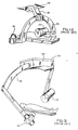
- A second approach is shown in Figures 12 and 13, illustrating two prior art devices. In the device shown in Figure 12, a single
structural member 20 carries anx-ray source 22 and anelectronic image intensifier 24 at its respective ends.Member 20 is supported by abrace 26 pivotally mounted to anoverhead support 28 for rotating the pattern of radiation passing fromsource 22 todetector 24 about a vertical axis without disturbing the relative alignment of source and detector. In the embodiment shown in Figure 13,source 22 anddetector 24 are rigidly mounted to the respective ends of a rigid C-shaped member 30 received in aguide 32, which again is pivotally mounted to anoverhead support 34. In this embodiment, member 30 can be rotated as before, or can be driven in either direction throughguide 32 to rotate the pattern of x-rays passing betweensource 22 anddetector 24 about the longitudinal axis of a patient. - The devices of Figures 12 and 13 seriously interfere with access to the patient by the physician, and when in motion can present a hazard to the patient and those working around the patient. Also, since in both prior art embodiments the mass of the x-ray tube and image intensifier is supported at a single point between them, support
members 20 and 30 are prone to gravitational and inertial bending moments and oscillations which complicate the problem of aimingsource 22 atdetector 24. Furthermore, such devices can be disturbing to the patient, who is encircled by machinery. These structures also are difficult or impossible to move out of the way when they are not in use, as the entire assembly must be moved as a unit and cannot be retracted or collapsed to provide head room. - In accordance with the invention, an x-ray source is supported by a ceiling mounted carriage and telescoping hanger which permit the source to translate longitudinally, laterally, and vertically and to independently pivot about vertical and horizontal axes. An electronic image intensifier or other detector is supported in similar fashion by an independent carriage and telescoping hanger. When the x-ray source and image intensifier are to be used for conducting a lateral fluoroscopic examination, the respective car- riages are coupled to a bridge member pivotally mounted to an overhead support.
- The vertical positioning means for the respective hangers are linked when the source and detector are ccupled to the bridge, so raising the source lowers the image intensifier, and vice versa. A mechanical linkage for moving the source and detector apart or together is coupled with the vertical positioning means so that, whether the central ray passing between the source and detector is disposed horizontally or not, the source and detector are always aimed at and diametrically opposed about an isocenter within the anatomy of interest. The pivoting of the. source and detector about their horizontal longitudinal axes is correlated with the vertical positions of the source and detector on their hangers by electronic position sensing means which transmit signals indicating the relative elevation and pivotal positions of the source and detector.
- As a result of the features described above, the source and detector are separable and can be retracted to the ceiling for compact storage when separated, and yet are mechanically linked when coupled to the bridge for tilting the central ray about vertical or longitudinal axes, permitting a wide selection of possible examination angles. The amount of equipment surrounding the patient is minimized, so access to the patient is maximized.
-
- Figure 1 is a perspective view of the present invention deployed in an examination room. A patient is shown positioned on an examination table and a known L-U arm assembly (40) is shown.
- Figures 2 and 3 are diagrammatic rear elevational views of two positions of the structure shown in Figure 1, illustrating the geometrical relations of the x-ray tube, detector, patient, and examination room according to the present invention.
- Figure 4 is a fragmentary bottom plan view of the structure shown in Figure 1, illustrating the mechanism for linking the x-ray source and detector together. Covers are removed and some parts are shown in section.
- Figure 5 is an enlarged detail view of the central portion of the structure shown in Figure 4.
- Figure 6 is an enlarged detail view of an outside portion of the structure shown in Figure 4.
- Figure 7 is a fragmentary side elevational view of the structure shown in Figure 4.
- Figure 8 is a rear elevational view of the x-ray tube hanger and carriage shown in Figure 1, and is representative of the structure of the x-ray image intensifier hanger and carriage as well.
- Figure 9 is an inside elevational view of the structure shown in Figure 8, with covers removed and the x-ray tube broken away.
- Figure 10 is an enlarged detail view of the lower end of the x-ray tube hanger shown in Figure 8.
- Figure 11 is a top plan view, partly in section, of the structure shown in Figure 10.
- Figures 12 and 13 are schematic perspective views showing two prior art structures. These views have already been discussed in the preceding Background of the Invention section.
- Although the disclosure hereof is detailed and exact to enable those skilled in the art to practice the invention, the physical embodiments herein disclosed merely exemplify the invention, which may be embodied in other specific structure. While.the best known embodiment has been described, the details may be changed without departing from the invention, which is defined by the claims.
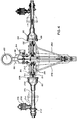
- Referring first to Figure 1,
patient 34 is supported on an examination table 36 which is cantilevered with respect to itsbase 38 to permit the equipment to be positioned at various points with respect to the patient. An L-Uarm x-ray apparatus 40 is supported by the floor of the room, and in this arrangement can be used for postero-anterior examination of the patient. A further description ofapparatus 40 can be found in the patent application previously incorporated by reference. The illustrated examination room includes anoverhead support 28, which in the illustrated embodiment is its ceiling. - An
x-ray source 22 and an x-ray detector 24 (here, a low powered x-ray tube and an electronic image intensifier for fluorographic studies) are respectively supported bytelescoping hangers upper ends x-ray source carriage 50 andx-ray detector carriage 52. Thelower ends hangers x-ray source 22 andimage intensifier 24 so the latter elements can respectively rotate about an axis 58 (which is parallel to the longitudinal axis throughpatient 34 and passes through the focal spot of x-ray source 22) and anaxis 60 which is parallel toaxis 58. -
Central ray 62 of the pattern of x-rays emitted fromsource 22 is aimed through an.isocenter 64, as is thelongitudinal axis 66 of image intensifier 24 (about which the x-ray pattern received and acted upon byimage intensifier 24 is disposed).Source 22 andimage intensifier 24 are supported adjacent to the respective lateral sides ofpatient 34. - Carriage 50 is pivotally mounted to a
roller truck 68 which is captured byparallel arms 70 and 72 of alateral track member 74 to permit lateral travel ofcarriage 50 and rotation of the carriage about a vertical axis.Lateral track member 74 is suspended from a pair of roller trucks such as 76 which travel on parallel, longitudinally disposed tracks such as 78 mounted tooverhead support 28 for permittingtrack member 74, and thusroller truck 68 andcarriage 50, to travel longitudinally. This system provides direct support forx-ray source 22, and sincehanger 42 is substantially vertical it has substantially no bending moment due to gravity. - Carriage 52 similarly is pivotally suspended from
roller truck 80,lateral track member 82, and roller trucks secured tomember 82 for traveling ontracks 84 and 86 mounted tooverhead support 28. - Although independently supported,
carriages member 88 pivotally secured tooverhead support 28 for rotation about a vertical axis passing throughisocenter 64. The coupling sites are first and second coupling means generally indicated byreference characters L-U arm 40 can be pivoted 90 de- qrees about its floor pivot, sox-ray source 22 can be aimed at a auxiliary detector mounted to arm 40 (as disclosed in the previously incorporated patent application). - Electric power and
control cable bundles x-ray source 22 anddetector 24 and for operating the invention, are routed fromsource 22 anddetector 24 to therespective carriages slides 98 carried in tracks such as 86 to a remote connection point (not shown). - Figures 2 and 3 show several geometric relationships which are maintained by the illustrated embodiment. B is the distance from
pivot axis 58 of x-raysource 22.to isocenter 64; C is the distance from pivot.axis 60 toisocenter 64; D is the horizontal component of B and lies along alateral axis 120 throughisocenter 64; E is the hcrizontal component of C and also lies onaxis 120; F is the vertical component of B; G is the vertical component of C; h is the angle between B and D; and i is the angle between C andE. Isocenter 64 is always stationary. B and C are always equal, and do not change for any position of the apparatus. F and h are respectively equal to G and i, and they all vary between zero (as in Figure 3) and a positive value (as in Figure 2). Thus,source 22 andimage intensifier 24 are always diametrically opposed throughisocenter 64 when coupled bybridge 88, and the source to image distance remains constant for any value of h and i.Central ray 62 andlongitudinal axis 66 are always directed throughisocenter 64 and are collinear. Finally, the entire assembly is rotatable as a rigid unit about avertical axis 122 throughisocenter 64. - To maintain the equality of F and G,
source 22 anddetector 24 are mechanically linked bybridge 88,carriages hangers source 22 ordetector 24 lowers the other by an equal amount. To keep B and C constant during such vertical travel,carriages bridge 88 when F and G are increased and away frombridge 88 when F and G are decreased. At the same time, microprocessor controlled servomechanisms aimsource 22 anddetector 24 towardisocenter 64 by varying h and i. The details of these mechanisms are shown in Figures 4-11. - In the illustrated embodiment,
image intensifier 24 can translate along itslongitudinal axis 66 with respect tohanger 44 to vary the isocenter to image distance without disturbing the foregoing relationships. This additional capability allows the magnification of the image to be varied without changing the other relationships just described. - Referring now to Figures 4-7,
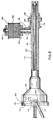
bridge 88 comprises a cross shaped horizontally disposedhousing 130 mounted to overhead support 28 (Figure 1) for pivoting about vertical axis 122 (which passes through isocenter 64).Housing 130 supports coaxialsplined shafts inboard end 136 ofshaft 132 is carried byball bearings truck 142 having rollers such as 144, 146, 148, and 150 which permit slight vertical translation oftruck 142 withinhousing 130. The outboard end ofshaft 132 is aprobe 152 for being received in thebore 154 of atubular member 156.Member 156 is supported partially withinx-ray source carriage 50 by rotation and thrust bearings such as 158,160. Afirst coupling member 164, here a male member, is splined to and slidable alongshaft 132.Second coupling member 166 is a female member secured tomember 156 to receivefirst coupling member 164.Second coupling member 166 includes adog 168 for being received in abore 170 infirst coupling member 164 so when the coupling members are coupled they rotate together. Couplingmembers First coupling member 164 is linked to a slide 172-which is slidably carried on splined shaft.132.Tubular member 156 includes acoaxial bevel gear 174 that meshes with abevel gear 176 secured to ashaft 178 to which a power take-offcable drum 180 is fixed. The cable drum shaft is rotatably secured to fixedmembers carriage 50 by thrust and rotation bearings. - A
counterpoise drum 185 is also mounted tocarriage 50. A flat spiral torsion spring (not shown) has its respective ends secured to drum 185 and its supports for exerting a counterclockwise (as seen in Figure 8) torque ondrum 185. Acable 186 is wound oncounterpoise drum 185, reeved about power take-off drum 180 and about anidler pulley 188, and has avertical run 189 best seen in Figure 8. Thelower end 190 ofrun 189 is anchored to the lower arm ofhanger 42. Windingcable 186 ontodrum 185 by turningdrum 180 withmotor 303 of the coupling drive raisessource 22 and collapseshanger 42, while rotatingdrum 180 in the other direction extendshanger 42 and thereby lowerssource 22. - An
encoder 192 is driven by anencoder cable 194 which is wound about another drum (not shown) fixed and coaxial with respect to power take-off drum 180.Cable 194 is run throughdirection changing block 196, and run vertically downward to ananchor 198 fixed to the lower arm ofhanger 42.Encoder 192 is thus enabled to transmit a signal corresponding to the vertical position ofsource 22. - For each of the structures identified by
reference numerals 136 through 198 there is a corresponding structure associated withsplined shaft 134,carriage 52, andhanger 44, although some of the latter elements are not separately illustrated. Reference characters for the illustrated features are as follows:inboard end 210 ofshaft 134;bearings truck 216;rollers tubular member 226; couplingmembers bevel gears cable drum 236 andcable 238. - A chain drive is provided to couple
splined shafts sprockets splined shafts sprockets shaft 258 secured to bridge 38 for rotation, and chaintension adjusting sprockets bridge 88. A firstendless chain 264, trained aboutsprockets sprocket 260, transmits the rotation ofshaft 134 to shaft 258 (and vice versa), and anidentical chain 266 transmits the rotation ofshaft 132 to shaft 258 (and vice versa). When the carriages are coupled to the bridge,cable 186 is wound bydrum 180 at the same rate thatcable 220 is unwound bydrum 218, and vice versa. The vertical travel ofsource 22 is thus equal and opposite to the vertical travel ofimage intensifier 24 when the assembly is coupled together as shown in the Figures. - The following mechanism is provided for spreading
carriages guide 270 is disposed perpendicularly toshafts slide 276 is slidably carried onguide 270, and linkarms pivct pin 282 to slide 276. The other ends oflink arms pivots 284 to the outer races of rotation bearings such as 286 carried on the respective slidessuch aa 172.Slide 276 is driven by anendless drive chain 288 having its respective ends reeved about asprocket 290 keyed toshaft 258 and asprocket 292 rotatably carried byshaft 294 journaled inbearings 296 and. 298 at the remote end ofbridge 88. Referring to Figure 7, a link 300 (which includes a chain tension adjustment) secureschain 288 to slide 276.Chain 288 is also reeved about anidler sprocket 301 rotatably secured to bridge 88 and about adrive sprocket 302 driven by areversible servomotor 303. Whensprocket 302 is driven one way byservomotor 303, slide 276 and linkarms x-ray source 22 is raised,image intensifier 24 is lowered, andcarriages arms source 22 to be lowered,image intensifier 24 to be raised, andcarriages slide 276 is in the position shown in phantom in Figure 4, that is,nearest shafts arms source 22 anddetector 24 are level withisocenter 64. The drive just described also includes apotentiometer 314 which senses and transmits the approximate rotational position ofshaft 258, which in turn is directly related to the exact vertical positions of the x-ray source and detector (provided by their respective encoders such as 192) and the separation between coupledcarriages - Figures 8, 9, 10, and 11 illustrate
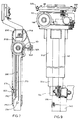
details'of hanger 42 andcarriage 50. (Althoughhanger 44,carriage 52 and associated structures are not specifically shown, they are identical to the corresponding structures ofhanger 42 andcarriage 50 as described herein.) In addition to parts previously identified in the preceding disclosure, Figures 8 and 9 show thatroller truck 68 includes roller assemblies such as 320, 322, and 324, of whichrollers track 72 androller 322 is carried in track 70.Hanger 42 comprisestelescoping segments arm 340 supporting apivot shaft 342 which is coaxial with the focal- point ofx-ray tube 22. Asheave 344 rotatably secured toshaft 342 receives acable 346 having its respective ends 347 secured to sheave 344 as shown in Figure 10.Cable 346 is driven by asheave 348 mounted on apivot shaft 350 rotatably carried by aframe 352 secured toarm 340.Sheave 348 is connected via a clutch and gear reduction 354 (shown in Figure 11) to areversible stepper motor 356 mounted to frame 352.Frame 352 can be made slidable with respect toarm 340 by loosening its fastenings for adjusting the tension ofcable 346, and anadjustment mechanism 358 bearing betweenarm 340 andframe 352 is provided for that purpose. - Figure 11 shows the details of clutch and
gear reduction 354.Cable 346 has been removed in Figure 11 for greater clarity of illustration.Stepper motor 356 has anoutput shaft 360 secured to a sheave 361 which is connected via a drive balt (not shown, for clarity) to asheave 363 secured to aninput shaft 364 of a high ratio in line gear reduction set.Shaft 364 is carried bybearings 366, 368 secured to a fixedmember 370.Member 370 is secured byfasteners 372, 374 to amember 376 offrame 352.Input shaft 364 is keyed to wave generator 378 - a ball bearing having an ellipticalinner race 380 and a flexibleouter race 382.Race 382 is pressed into flexible spline ring 384, which has 240 teeth on its outside edge. Spline ring 384 is received within a fixedring gear 386, having 242 internal teeth and secured byfasteners 388 to fixedmember 370, and also within arotating ring gear 390 having 240 internal teeth and secured byfasteners 392 to a disc 293 secured to pivotshaft 350. Rotation ofelliptical race 380 flexes the teeth of diametrically opposed portions of spline ring 384 outwardly to sequentially mesh with the adjacent teeth of ring gears 386 and 390.Ring gear 386 is fixed and has two more teeth than spline 384, therefore permitting spline 384 to make two revolutions contrary to the rotation ofinner race 380 for each 240 revolutions ofinner race 380.Ring gear 390, which has the same number of teeth as spline 384, rotates at the same rate as spline 384. The resulting drive ratio is thus 240:2, or 120:1. -
Pivot shaft 350 is supported by bearing 394 (secured to stationary member 396) and drives sheave 248 via a normally engaged clutch generally indicated at 398 (shown disengaged).Clutch 398 comorises aferromagnetic plunger 400 spliced to and axially slidable to a slight degree alongpivot shaft 350; first and secondclutch plates retainer 406, the latter secured nonrotatably but axially movable relative to magnetic coil housing 408 (which in turn is secured to sheave 348);compression coil springs 412 carried onslidable guide shafts 410 and bearing betweencoil housing 408 and second clutch plate 404: and a conductive coil shown schematically at 414, havingterminals plunger 400 andclutch plate 404. -
Clutch 398 is engaged when no power is fed tocoil 414 becausesprings 412 urgeclutch plate 402 againstclutch plate 404. Because of the high gear reduction betweenshaft 360 andsheave 348, ifstepper motor 356 is not energized and clutch 398 is engagedx-ray source 22 will maintain its pivotal position. By energizingcoil 414, which counteracts the bias ofsprings 412 and thereby disengages the clutch plates,sheave 348, and thus sheave 344, are free to rotate to allow manual pivoting of the x-ray source. - The pivotal position of
x-ray tube 22 is transmitted by aposition encoder 420 via a timingpulley 422,timing belt 424, and a timingpulley 426 mounted onpivot shaft 342. - The
x-ray image intensifier 24 includes essentially identical structure, including position encoders for hanger length and pivotal position, a gear reduction, a clutch, and f=ame elements, to allow it to be manually positioned when the clutch is disengaged and automatically positioned when the clutch is engaged, the pivotal position being indicated by the position encoder regardless of the condition of the clutch. - When the hangers are not in use,
couplings hangers hanger 44, and operatesservomotor 303 for the bridge coupling mechanism to rotatecoupling member 228 to the correct position for coupling withcoupling member 230. Second, the image intensifier is manually extended or retracted to about the correct height and pivoted (with its clutch released) to approximately the correct position for the desired study.Servomotor 303 automatically compensates for any vertical travel ofhanger 44 as already explained. Third, theimage intensifier 24 is docked to bridge 88 andcoupling members image intensifier 24 through isocenter. - Next, the
x-ray source 22 and associatedhanger 42 andcarriage 50 are manually operated to bringsource 22 to approximately the proper height.coupling members source 22 is adjusted as necessary to line up the coupling members, and they are coupled. The microprocessor con- trcl is instructed to read the position signals transmitted byposition encoders x-ray source 22, and (with clutch 398 engaged)servomotor 356 is actuated as necessary to correlate the pivotal position ofsource 22 with its height, thereby aiming its central ray through isocenter. - Although a preferred mode of operation is described, it will be appreciated that other mdes of operation could be practiced with the same apparatus within the scope of the present invention.
Claims (14)
Applications Claiming Priority (2)
| Application Number | Priority Date | Filing Date | Title |
|---|---|---|---|
| US421603 | 1982-09-22 | ||
| US06/421,603 US4501011A (en) | 1982-09-22 | 1982-09-22 | Angulating lateral fluoroscopic suspension |
Publications (2)
| Publication Number | Publication Date |
|---|---|
| EP0103742A1 true EP0103742A1 (en) | 1984-03-28 |
| EP0103742B1 EP0103742B1 (en) | 1987-01-21 |
Family
ID=23671250
Family Applications (1)
| Application Number | Title | Priority Date | Filing Date |
|---|---|---|---|
| EP83108033A Expired EP0103742B1 (en) | 1982-09-22 | 1983-08-13 | Angulating lateral fluoroscopic suspension |
Country Status (5)
| Country | Link |
|---|---|
| US (1) | US4501011A (en) |
| EP (1) | EP0103742B1 (en) |
| JP (1) | JPS59131333A (en) |
| DE (1) | DE3369246D1 (en) |
| IL (1) | IL68905A (en) |
Cited By (3)
| Publication number | Priority date | Publication date | Assignee | Title |
|---|---|---|---|---|
| DE10322281A1 (en) * | 2003-05-16 | 2004-12-23 | Ge Inspection Technologies Ahrensburg Gmbh & Co. Kg | Manipulator for an X-ray device |
| CN100405978C (en) * | 2006-04-18 | 2008-07-30 | 东软飞利浦医疗设备系统有限责任公司 | Device for connection rays source of X-ray apparatus and imaging system |
| WO2012088816A1 (en) * | 2010-12-31 | 2012-07-05 | 清华大学 | Detection device |
Families Citing this family (60)
| Publication number | Priority date | Publication date | Assignee | Title |
|---|---|---|---|---|
| US4582995A (en) * | 1984-06-18 | 1986-04-15 | Technicare Corporation | Spatial registration correction for rotational gamma cameras |
| EP0220501B1 (en) * | 1985-10-09 | 1989-05-31 | Siemens Aktiengesellschaft | Diagnostic x-ray installation comprising components to be positioned by means of a control device |
| SE455568B (en) * | 1985-12-20 | 1988-07-25 | Ao Medical Products Ab | SET AND PLANT FOR X-ray PHOTOGRAPHY OR EQUIVALENT USING AN EXCELLENT PATIENT TABLE |
| US4741015A (en) * | 1986-12-05 | 1988-04-26 | B. C. Medical Compagnie Limitee | Universal X-ray unit |
| JPH02503989A (en) * | 1987-06-18 | 1990-11-22 | カール―エリック・オールソン | Methods and apparatus for radiography or the like |
| DE8716725U1 (en) * | 1987-12-18 | 1989-04-13 | Siemens Ag, 1000 Berlin Und 8000 Muenchen, De | |
| JPH01185246A (en) * | 1988-01-19 | 1989-07-24 | Toshiba Corp | X-ray photographing device |
| DE8803431U1 (en) * | 1988-03-14 | 1989-07-13 | Siemens Ag, 1000 Berlin Und 8000 Muenchen, De | |
| JPH02159256A (en) * | 1988-12-13 | 1990-06-19 | Toshiba Corp | X-ray tube support apparatus |
| US4987585A (en) * | 1989-04-04 | 1991-01-22 | General Electric Company | X-ray positioner for multi-axis profiling |
| JPH0683708B2 (en) * | 1989-11-17 | 1994-10-26 | 株式会社東芝 | X-ray equipment |
| US5199060A (en) * | 1990-06-04 | 1993-03-30 | Kabushiki Kaisha Toshiba | X-ray photographing apparatus |
| JPH04208137A (en) * | 1990-11-30 | 1992-07-29 | Toshiba Corp | X-ray photographing device |
| US5287546A (en) * | 1992-09-14 | 1994-02-15 | Lunar Corporation | Patient positioning apparatus for bone scanning |
| JP2663788B2 (en) * | 1992-02-28 | 1997-10-15 | 株式会社島津製作所 | X-ray equipment |
| US6064717A (en) * | 1997-11-21 | 2000-05-16 | Rigaku/Usa, Inc. | Unrestricted motion apparatus and method for x-ray diffraction analysis |
| US6851851B2 (en) * | 1999-10-06 | 2005-02-08 | Hologic, Inc. | Digital flat panel x-ray receptor positioning in diagnostic radiology |
| US6434216B1 (en) | 2001-03-16 | 2002-08-13 | Ge Medical Systems Global Technology Company, Llc | Source pin loader method and apparatus for positron emission tomography |
| DE10142441C1 (en) * | 2001-08-31 | 2003-03-13 | Siemens Ag | Ceiling-mounted diagnostic X-ray device has X-ray source and radiation detector each moved along perpendicular guide rail between opposite sides of patient table |
| EP1306053A3 (en) * | 2001-10-15 | 2004-01-07 | Siemens Aktiengesellschaft | Versatile radiography system |
| US6814489B2 (en) * | 2001-11-23 | 2004-11-09 | Ge Medical Systems Global Technology Company, Llc | 3D reconstruction system and method utilizing a variable X-ray source to image distance |
| JP3888203B2 (en) * | 2002-04-02 | 2007-02-28 | 株式会社島津製作所 | Round-trip X-ray system |
| US7963695B2 (en) | 2002-07-23 | 2011-06-21 | Rapiscan Systems, Inc. | Rotatable boom cargo scanning system |
| US8275091B2 (en) | 2002-07-23 | 2012-09-25 | Rapiscan Systems, Inc. | Compact mobile cargo scanning system |
| US6794667B2 (en) * | 2002-10-31 | 2004-09-21 | Ge Medical Systems Global Technology Company, Llc | Source pin loading methods and apparatus for positron emission tomography |
| US7126142B2 (en) * | 2002-10-31 | 2006-10-24 | Ge Medical Systems Global Technology Company, Llc | Source loading apparatus for imaging systems |
| DE10311456A1 (en) * | 2003-03-14 | 2004-09-23 | Siemens Ag | X-ray source ceiling mount support arm has horizontal axis above holder and arm undersides so that source remains below arm and holder |
| US6928141B2 (en) | 2003-06-20 | 2005-08-09 | Rapiscan, Inc. | Relocatable X-ray imaging system and method for inspecting commercial vehicles and cargo containers |
| US7056016B2 (en) * | 2003-12-23 | 2006-06-06 | General Electric Company | X-ray source support assembly |
| DE102004011671A1 (en) * | 2004-03-10 | 2005-09-29 | Siemens Ag | X-ray inspection device for ceiling mounting |
| US8406845B2 (en) * | 2004-09-01 | 2013-03-26 | University Of Tennessee Research Foundation | Method and apparatus for imaging tracking |
| US20060159229A1 (en) * | 2005-01-14 | 2006-07-20 | Bede Scientific Instruments Limited | Positioning apparatus |
| EP1858413A1 (en) * | 2005-03-07 | 2007-11-28 | Koninklijke Philips Electronics N.V. | Cable guiding for a ceiling support of an x-ray device |
| DE102005014188A1 (en) * | 2005-03-29 | 2006-10-12 | Siemens Ag | Device for taking projection images |
| US7471764B2 (en) | 2005-04-15 | 2008-12-30 | Rapiscan Security Products, Inc. | X-ray imaging system having improved weather resistance |
| US7624967B1 (en) * | 2006-04-19 | 2009-12-01 | Par Systems, Inc. | Opposed-rope hoist driven telescoping mast |
| US7526064B2 (en) | 2006-05-05 | 2009-04-28 | Rapiscan Security Products, Inc. | Multiple pass cargo inspection system |
| US7481578B2 (en) * | 2006-09-18 | 2009-01-27 | Cartstream Health, Inc. | Digital radiography apparatus |
| CN101301204B (en) * | 2007-05-11 | 2011-03-09 | Ge医疗系统环球技术有限公司 | X-ray image-forming system |
| US8300762B2 (en) * | 2007-11-16 | 2012-10-30 | J. Morita Manufacturing Corporation | X-ray CT imaging apparatus |
| CN101455570B (en) | 2007-12-14 | 2012-04-25 | Ge医疗系统环球技术有限公司 | X ray radiation device and X ray imaging system |
| GB0809110D0 (en) | 2008-05-20 | 2008-06-25 | Rapiscan Security Products Inc | Gantry scanner systems |
| US7954996B2 (en) * | 2008-07-08 | 2011-06-07 | General Electric Company | Positioning system with tilting arm support for imaging devices |
| DE102008032294A1 (en) * | 2008-07-09 | 2010-01-14 | Siemens Aktiengesellschaft | X-ray equipment |
| US8794832B2 (en) * | 2008-09-03 | 2014-08-05 | Kabushiki Kaisha Toshiba | X-ray diagnostic imaging apparatus and X-ray apparatus |
| CN101685311B (en) * | 2008-09-24 | 2012-09-05 | 深圳迈瑞生物医疗电子股份有限公司 | Stroke control device |
| JPWO2011162149A1 (en) * | 2010-06-21 | 2013-08-19 | 株式会社日立メディコ | Ceiling-running X-ray imaging apparatus and control method thereof |
| CN103675932B (en) * | 2010-12-31 | 2016-09-21 | 清华大学 | Check device |
| CN102613980B (en) * | 2011-01-31 | 2015-07-22 | 深圳迈瑞生物医疗电子股份有限公司 | Radiological image equipment and automatic following method thereof |
| US9218933B2 (en) | 2011-06-09 | 2015-12-22 | Rapidscan Systems, Inc. | Low-dose radiographic imaging system |
| DE102012005899A1 (en) * | 2012-03-15 | 2013-09-19 | Fraunhofer-Gesellschaft zur Förderung der angewandten Forschung e.V. | Detector arrangement for taking X-ray images of an object to be imaged |
| US9791590B2 (en) | 2013-01-31 | 2017-10-17 | Rapiscan Systems, Inc. | Portable security inspection system |
| KR101460535B1 (en) * | 2013-02-21 | 2014-11-12 | 삼성전자 주식회사 | X-ray image apparatus |
| USD757940S1 (en) * | 2014-10-02 | 2016-05-31 | Siemens Aktiengesellschaft | Radiography and fluoroscopy system |
| CN107847210B (en) | 2015-07-16 | 2021-11-12 | 皇家飞利浦有限公司 | Apparatus for remote fluoroscopy, near fluoroscopy and radiology |
| DE102016013315A1 (en) * | 2016-11-08 | 2018-05-09 | RayScan Technologies GmbH | Measuring system and method for operating a measuring system |
| CN106725557B (en) | 2017-01-19 | 2021-01-08 | 上海联影医疗科技股份有限公司 | X-ray imaging apparatus and control method thereof |
| JP6878330B2 (en) * | 2018-02-09 | 2021-05-26 | 株式会社東芝 | Particle therapy device |
| JP7107076B2 (en) * | 2018-08-06 | 2022-07-27 | 株式会社島津製作所 | X-ray equipment |
| EP3646789A1 (en) | 2018-10-30 | 2020-05-06 | Koninklijke Philips N.V. | X-ray imaging arrangement |
Citations (4)
| Publication number | Priority date | Publication date | Assignee | Title |
|---|---|---|---|---|
| US3549885A (en) * | 1967-07-10 | 1970-12-22 | Saab Ab | Apparatus for x-raying on two mutually perpendicular axes with a pair of x-ray sources |
| US3659099A (en) * | 1968-10-19 | 1972-04-25 | Philips Corp | X-ray apparatus for screening and radiographs in two directions |
| US3776500A (en) * | 1971-07-16 | 1973-12-04 | Picker Corp | X-ray apparatus having a telescopic columnar support |
| US4339825A (en) * | 1980-10-31 | 1982-07-13 | General Electric Company | Bi-plane angiographic apparatus |
Family Cites Families (5)
| Publication number | Priority date | Publication date | Assignee | Title |
|---|---|---|---|---|
| US2818510A (en) * | 1953-07-23 | 1957-12-31 | Philips Corp | Diagnostic x-ray device |
| US4024401A (en) * | 1975-11-17 | 1977-05-17 | General Electric Company | X-ray apparatus |
| JPS5676937A (en) * | 1979-11-28 | 1981-06-24 | Tokyo Shibaura Electric Co | Xxray photographing device |
| JPS56163636A (en) * | 1980-05-21 | 1981-12-16 | Tokyo Shibaura Electric Co | X-ray photographing device |
| JPS5789849A (en) * | 1980-11-21 | 1982-06-04 | Tokyo Shibaura Electric Co | X-ray photographing apparatus |
-
1982
- 1982-09-22 US US06/421,603 patent/US4501011A/en not_active Expired - Fee Related
-
1983
- 1983-06-07 IL IL68905A patent/IL68905A/en unknown
- 1983-08-13 EP EP83108033A patent/EP0103742B1/en not_active Expired
- 1983-08-13 DE DE8383108033T patent/DE3369246D1/en not_active Expired
- 1983-09-21 JP JP58173280A patent/JPS59131333A/en active Pending
Patent Citations (4)
| Publication number | Priority date | Publication date | Assignee | Title |
|---|---|---|---|---|
| US3549885A (en) * | 1967-07-10 | 1970-12-22 | Saab Ab | Apparatus for x-raying on two mutually perpendicular axes with a pair of x-ray sources |
| US3659099A (en) * | 1968-10-19 | 1972-04-25 | Philips Corp | X-ray apparatus for screening and radiographs in two directions |
| US3776500A (en) * | 1971-07-16 | 1973-12-04 | Picker Corp | X-ray apparatus having a telescopic columnar support |
| US4339825A (en) * | 1980-10-31 | 1982-07-13 | General Electric Company | Bi-plane angiographic apparatus |
Cited By (3)
| Publication number | Priority date | Publication date | Assignee | Title |
|---|---|---|---|---|
| DE10322281A1 (en) * | 2003-05-16 | 2004-12-23 | Ge Inspection Technologies Ahrensburg Gmbh & Co. Kg | Manipulator for an X-ray device |
| CN100405978C (en) * | 2006-04-18 | 2008-07-30 | 东软飞利浦医疗设备系统有限责任公司 | Device for connection rays source of X-ray apparatus and imaging system |
| WO2012088816A1 (en) * | 2010-12-31 | 2012-07-05 | 清华大学 | Detection device |
Also Published As
| Publication number | Publication date |
|---|---|
| IL68905A (en) | 1987-12-20 |
| DE3369246D1 (en) | 1987-02-26 |
| IL68905A0 (en) | 1983-10-31 |
| JPS59131333A (en) | 1984-07-28 |
| EP0103742B1 (en) | 1987-01-21 |
| US4501011A (en) | 1985-02-19 |
Similar Documents
| Publication | Publication Date | Title |
|---|---|---|
| EP0103742B1 (en) | Angulating lateral fluoroscopic suspension | |
| US4358856A (en) | Multiaxial x-ray apparatus | |
| US6789941B1 (en) | Dual C-arm angiographic device for flat panel receptor | |
| US4979202A (en) | Support structure for X-ray imaging apparatus | |
| US4426725A (en) | Biplanar variable angle X-ray examining apparatus | |
| US8568028B2 (en) | Mobile radiography unit having collapsible support column | |
| US4363128A (en) | X-Ray drive apparatus | |
| US4741015A (en) | Universal X-ray unit | |
| US4435830A (en) | X-Ray apparatus | |
| JP2004173756A (en) | Parallel link table and tomographic imaging equipment | |
| CN102670223A (en) | Sliding counterbalanced C-arm positioning devices and methods for using such devices | |
| JPS6411294B2 (en) | ||
| US20110249806A1 (en) | Mobile radiography unit having collapsible support column | |
| US20240058079A1 (en) | Seven degree of freedom positioning device for robotic surgery | |
| US20120321050A1 (en) | Device for supporting elements for connecting a mobile x-ray machine and x-ray machine provided with such a supporting device | |
| US7556427B2 (en) | X-ray radiography apparatus and X-ray generator moving device | |
| CN216021094U (en) | Patient standing table, CT scanning device and CT scanning system | |
| US4365345A (en) | Servo operated fluoroscopic table | |
| EP0114054B1 (en) | X-ray tomography table having a virtual fulcrum arm pivot | |
| US5201088A (en) | Patient examination table having a simplified tilt mechanism | |
| US5325413A (en) | X-ray examination apparatus | |
| US4879737A (en) | Articulated X-ray stand arm | |
| CN212307876U (en) | Automatic medical bed | |
| US4190774A (en) | Radiographic table system | |
| CN1026059C (en) | X-ray tomography apperatus |
Legal Events
| Date | Code | Title | Description |
|---|---|---|---|
| PUAI | Public reference made under article 153(3) epc to a published international application that has entered the european phase |
Free format text: ORIGINAL CODE: 0009012 |
|
| AK | Designated contracting states |
Designated state(s): DE GB NL |
|
| 17P | Request for examination filed |
Effective date: 19840918 |
|
| GRAA | (expected) grant |
Free format text: ORIGINAL CODE: 0009210 |
|
| AK | Designated contracting states |
Kind code of ref document: B1 Designated state(s): DE GB NL |
|
| REF | Corresponds to: |
Ref document number: 3369246 Country of ref document: DE Date of ref document: 19870226 |
|
| PGFP | Annual fee paid to national office [announced via postgrant information from national office to epo] |
Ref country code: NL Payment date: 19870831 Year of fee payment: 5 |
|
| PLBE | No opposition filed within time limit |
Free format text: ORIGINAL CODE: 0009261 |
|
| STAA | Information on the status of an ep patent application or granted ep patent |
Free format text: STATUS: NO OPPOSITION FILED WITHIN TIME LIMIT |
|
| 26N | No opposition filed | ||
| PG25 | Lapsed in a contracting state [announced via postgrant information from national office to epo] |
Ref country code: GB Free format text: LAPSE BECAUSE OF NON-PAYMENT OF DUE FEES Effective date: 19880813 |
|
| PG25 | Lapsed in a contracting state [announced via postgrant information from national office to epo] |
Ref country code: NL Effective date: 19890301 |
|
| NLV4 | Nl: lapsed or anulled due to non-payment of the annual fee | ||
| PG25 | Lapsed in a contracting state [announced via postgrant information from national office to epo] |
Ref country code: DE Effective date: 19890503 |
|
| GBPC | Gb: european patent ceased through non-payment of renewal fee |