DE102012109729A1 - Measuring system for determining volumetric flow during measuring interval of total flowed volume of flowing medium, particularly liquid or gas, has vibration element for guiding flowing portion of medium, where vibration element has lumen - Google Patents
Measuring system for determining volumetric flow during measuring interval of total flowed volume of flowing medium, particularly liquid or gas, has vibration element for guiding flowing portion of medium, where vibration element has lumen Download PDFInfo
- Publication number
- DE102012109729A1 DE102012109729A1 DE201210109729 DE102012109729A DE102012109729A1 DE 102012109729 A1 DE102012109729 A1 DE 102012109729A1 DE 201210109729 DE201210109729 DE 201210109729 DE 102012109729 A DE102012109729 A DE 102012109729A DE 102012109729 A1 DE102012109729 A1 DE 102012109729A1
- Authority
- DE
- Germany
- Prior art keywords
- measuring
- vibrating element
- vibration
- signal
- measuring system
- Prior art date
- Legal status (The legal status is an assumption and is not a legal conclusion. Google has not performed a legal analysis and makes no representation as to the accuracy of the status listed.)
- Pending
Links
Images


Classifications
-
- G—PHYSICS
- G01—MEASURING; TESTING
- G01F—MEASURING VOLUME, VOLUME FLOW, MASS FLOW OR LIQUID LEVEL; METERING BY VOLUME
- G01F1/00—Measuring the volume flow or mass flow of fluid or fluent solid material wherein the fluid passes through a meter in a continuous flow
- G01F1/76—Devices for measuring mass flow of a fluid or a fluent solid material
- G01F1/78—Direct mass flowmeters
- G01F1/80—Direct mass flowmeters operating by measuring pressure, force, momentum, or frequency of a fluid flow to which a rotational movement has been imparted
- G01F1/84—Coriolis or gyroscopic mass flowmeters
- G01F1/845—Coriolis or gyroscopic mass flowmeters arrangements of measuring means, e.g., of measuring conduits
- G01F1/8468—Coriolis or gyroscopic mass flowmeters arrangements of measuring means, e.g., of measuring conduits vibrating measuring conduits
- G01F1/849—Coriolis or gyroscopic mass flowmeters arrangements of measuring means, e.g., of measuring conduits vibrating measuring conduits having straight measuring conduits
- G01F1/8495—Coriolis or gyroscopic mass flowmeters arrangements of measuring means, e.g., of measuring conduits vibrating measuring conduits having straight measuring conduits with multiple measuring conduits
-
- G—PHYSICS
- G01—MEASURING; TESTING
- G01F—MEASURING VOLUME, VOLUME FLOW, MASS FLOW OR LIQUID LEVEL; METERING BY VOLUME
- G01F1/00—Measuring the volume flow or mass flow of fluid or fluent solid material wherein the fluid passes through a meter in a continuous flow
- G01F1/76—Devices for measuring mass flow of a fluid or a fluent solid material
- G01F1/78—Direct mass flowmeters
- G01F1/80—Direct mass flowmeters operating by measuring pressure, force, momentum, or frequency of a fluid flow to which a rotational movement has been imparted
- G01F1/84—Coriolis or gyroscopic mass flowmeters
- G01F1/8409—Coriolis or gyroscopic mass flowmeters constructional details
- G01F1/8413—Coriolis or gyroscopic mass flowmeters constructional details means for influencing the flowmeter's motional or vibrational behaviour, e.g., conduit support or fixing means, or conduit attachments
-
- G—PHYSICS
- G01—MEASURING; TESTING
- G01F—MEASURING VOLUME, VOLUME FLOW, MASS FLOW OR LIQUID LEVEL; METERING BY VOLUME
- G01F1/00—Measuring the volume flow or mass flow of fluid or fluent solid material wherein the fluid passes through a meter in a continuous flow
- G01F1/76—Devices for measuring mass flow of a fluid or a fluent solid material
- G01F1/78—Direct mass flowmeters
- G01F1/80—Direct mass flowmeters operating by measuring pressure, force, momentum, or frequency of a fluid flow to which a rotational movement has been imparted
- G01F1/84—Coriolis or gyroscopic mass flowmeters
- G01F1/8409—Coriolis or gyroscopic mass flowmeters constructional details
- G01F1/8422—Coriolis or gyroscopic mass flowmeters constructional details exciters
-
- G—PHYSICS
- G01—MEASURING; TESTING
- G01F—MEASURING VOLUME, VOLUME FLOW, MASS FLOW OR LIQUID LEVEL; METERING BY VOLUME
- G01F1/00—Measuring the volume flow or mass flow of fluid or fluent solid material wherein the fluid passes through a meter in a continuous flow
- G01F1/76—Devices for measuring mass flow of a fluid or a fluent solid material
- G01F1/78—Direct mass flowmeters
- G01F1/80—Direct mass flowmeters operating by measuring pressure, force, momentum, or frequency of a fluid flow to which a rotational movement has been imparted
- G01F1/84—Coriolis or gyroscopic mass flowmeters
- G01F1/8409—Coriolis or gyroscopic mass flowmeters constructional details
- G01F1/8427—Coriolis or gyroscopic mass flowmeters constructional details detectors
-
- G—PHYSICS
- G01—MEASURING; TESTING
- G01F—MEASURING VOLUME, VOLUME FLOW, MASS FLOW OR LIQUID LEVEL; METERING BY VOLUME
- G01F1/00—Measuring the volume flow or mass flow of fluid or fluent solid material wherein the fluid passes through a meter in a continuous flow
- G01F1/76—Devices for measuring mass flow of a fluid or a fluent solid material
- G01F1/78—Direct mass flowmeters
- G01F1/80—Direct mass flowmeters operating by measuring pressure, force, momentum, or frequency of a fluid flow to which a rotational movement has been imparted
- G01F1/84—Coriolis or gyroscopic mass flowmeters
- G01F1/8409—Coriolis or gyroscopic mass flowmeters constructional details
- G01F1/8436—Coriolis or gyroscopic mass flowmeters constructional details signal processing
-
- G—PHYSICS
- G01—MEASURING; TESTING
- G01F—MEASURING VOLUME, VOLUME FLOW, MASS FLOW OR LIQUID LEVEL; METERING BY VOLUME
- G01F1/00—Measuring the volume flow or mass flow of fluid or fluent solid material wherein the fluid passes through a meter in a continuous flow
- G01F1/76—Devices for measuring mass flow of a fluid or a fluent solid material
- G01F1/78—Direct mass flowmeters
- G01F1/80—Direct mass flowmeters operating by measuring pressure, force, momentum, or frequency of a fluid flow to which a rotational movement has been imparted
- G01F1/84—Coriolis or gyroscopic mass flowmeters
- G01F1/845—Coriolis or gyroscopic mass flowmeters arrangements of measuring means, e.g., of measuring conduits
- G01F1/8468—Coriolis or gyroscopic mass flowmeters arrangements of measuring means, e.g., of measuring conduits vibrating measuring conduits
- G01F1/849—Coriolis or gyroscopic mass flowmeters arrangements of measuring means, e.g., of measuring conduits vibrating measuring conduits having straight measuring conduits
Abstract
Description
Die Erfindung betrifft ein Meßsystem zum Ermitteln eines Volumendurchflusses, nämlich eines während eines vorgebbaren oder vorab bestimmten Meßintervalls insgesamt geflossenen Volumens, und/oder einer Volumendurchflußrate eines in einer Rohrleitung, insb. zumindest zeitweise mit einer Massendurchflußrate von mehr als 100 t/h, strömenden Mediums, insb. einer Flüssigkeit oder eines Gases.The invention relates to a measuring system for determining a volumetric flow, namely a total volume flowed during a predeterminable or predetermined measurement interval, and / or a volumetric flow rate of a medium flowing in a pipeline, in particular at least at times at a mass flow rate of more than 100 t / h , esp. Of a liquid or a gas.
In der Prozeßmeß- und Automatisierungstechnik werden für die Messung physikalischer Parameter, wie z.B. dem Massedurchfluß bzw. der Massendurchflußrate, dem Volumendurchfluß bzw. der Volumendurchflußrate, sowie der Dichte und/oder der Viskosität, von in Rohrleitungen strömenden Medien oftmals solche – zumeist als In-Line-Meßgeräte in Kompaktbauweise ausgebildeten – Meßsysteme verwendet, die mittels eines vom Medium durchströmten Meßaufnehmers vom Vibrationstyp und einer daran angeschlossenen Meß- und Treiberschaltung, im Medium Reaktionskräfte, wie z.B. mit dem Massedurchfluß korrespondierende Corioliskräfte, mit der Dichte des Mediums korrespondierende Trägheitskräfte und/oder mit der Viskosität des Mediums korrespondierende Reibungskräfte etc., bewirken und von diesen abgeleitet ein den jeweiligen Massedurchfluß, die jeweilige Viskosität und/oder ein die jeweilige Dichte des Mediums repräsentierendes Meßsignal erzeugen. Derartige, insb. als Coriolis-Massedurchflußmesser oder Coriolis-Massedurchfluß-/Dichtemesser ausgebildete, Meßaufnehmer bzw. damit gebildete Meßsysteme sind z.B. in der
Jeder der Meßaufnehmer weist ein Gehäuse auf, von dem ein einlaßseitiges erstes Gehäuseende zumindest anteilig mittels eines wenigstens zwei jeweils voneinander beabstandeten kreiszylindrische oder kegelförmige Strömungsöffnungen aufweisenden ersten Strömungsteiler und ein auslaßseitiges zweites Gehäuseende zumindest anteilig mittels eines wenigstens zwei jeweils voneinander beabstandeten Strömungsöffnungen aufweisenden zweiten Strömungsteilers gebildet sind. Bei einigen der in der
Zum Führen des zumindest zeitweise strömenden, ggf. auch mehrphasigen, Mediums umfassen die Meßaufnehmer desweiteren jeweils zwei – im Falle etwa der
Die Meßrohre, mithin das damit gebildete Vibrationselement, werden zum Erzeugen oben genannter Reaktionskräfte, angetrieben von wenigstens einem dem Erzeugen bzw. Aufrechterhalten von mechanischen Schwingungen, insb. von Biegeschwingungen, der Meßrohre im sogenannten Antriebs- oder Nutzmode dienenden Schwingungserreger, im Betrieb vibrieren gelassen. Die Schwingungen im Nutzmode (Nutzmode-Schwingungen) sind zumeist, insb. bei Verwendung des Meßaufnehmers als Coriolis-Massedurchfluß- und/oder Dichtemesser, zumindest anteilig als laterale Biege-Schwingungen jedes der Meßrohre jeweils um eine gedachte Schwingungsachse ausgebildet und im Falle von durch die Meßrohre hindurchströmendem Medium infolge von darin induzierten Corioliskräften durch zusätzliche, frequenzgleiche Schwingungen im sogenannten Coriolismode überlagert (Coriolismode-Schwingungen). Dementsprechend ist die – hier zumeist elektrodynamische – Erregeranordnung im Falle gerader Meßrohre derart ausgebildet, daß damit die wenigstens zwei Meßrohre im Nutzmode zumindest anteilig, insb. auch überwiegend, zu gegengleichen, mithin gegengleichen, Biegeschwingungen in einer gemeinsamen Schwingungsebene differentiell – also durch Eintrag gleichzeitig entlang einer gemeinsamen Wirkungslinie, jedoch in entgegengesetzter Richtung wirkender Erregerkräfte – anregbar sind.The measuring tubes, thus the vibration element thus formed, are vibrated during operation for generating above-mentioned reaction forces, driven by at least one generating or maintaining mechanical vibrations, esp. Of bending vibrations, the measuring tubes in the so-called drive or Nutzmode serving vibration exciter. The oscillations in Nutzmode (Nutzmode oscillations) are usually, esp. When using the transducer as Coriolis Massedurchfluß- and / or density meter, at least partially formed as a lateral bending oscillations of each of the measuring tubes each about an imaginary axis of vibration and in the case of Measuring tubes flowing medium as a result of induced therein Coriolis forces by additional, equal frequency oscillations in the so-called Coriolis mode superimposed (Coriolismode oscillations). Accordingly, the excitation arrangement - here mostly electrodynamic - in the case of straight measuring tubes designed so that at least partially, especially in comparison to the at least two measuring tubes, esp. Also prevail, thus gegengleichen, bending vibrations in a common plane of oscillation differentially - ie by entry simultaneously along a common line of action, but in the opposite direction acting exciters - excitable.
Zum Erfassen von Vibrationen des Vibrationselements, insb. von mittels der Erregeranordnung angeregten Biegeschwingungen der Meßrohre, und zum Erzeugen von Vibrationen des Vibrationselements repräsentierenden Schwingungsmeßsignalen weisen Meßaufnehmer der vorgenannten Art ferner jeweils eine auf relative Bewegungen eines oder mehrerer der Meßrohre reagierende, zumeist ebenfalls elektrodynamische Vibrationssensoranordnung auf. Typischerweise ist die Vibrationssensoranordnung mittels eines einlaßseitigen, Schwingungen der Meßrohre differentiell – also lediglich relative Bewegungen der Meßrohre – erfassenden Schwingungssensors sowie eines auslaßseitigen, Schwingungen der Meßrohre differentiell erfassenden Schwingungssensors gebildet ist, wobei jeder ein von Vibrationen des Vibrationselements abhängiges Schwingungssignal generiert, das eine der momentanen Schwingungsfrequenz des Vibrationselements entsprechende Signalfrequenz aufweist, derart, daß zwischen dem Schwingungssignal des einlaßseitigen Schwingungssensors und dem Schwingungssignal des auslaßseitigen Schwingungssensors eine von der momentanen Massendurchflußrate abhängige, relative Phasendifferenz existiert. Jeder der üblicherweise einander baugleichen Schwingungssensoren ist mittels eines am ersten Meßrohr gehalterten Permanentmagneten und einer von dessen Magnetfeld durchfluteten, am zweiten Meßrohr gehalterten Zylinderspule gebildet ist.For detecting vibrations of the vibrating element, esp. Of excited by the exciter assembly bending vibrations of the measuring tubes, and for generating vibrations of the vibrating element representing Schwingungsmeßsignalen, transducers of the aforementioned type also each have a relative movements of one or more of the measuring tubes responsive, usually also electrodynamic vibration sensor arrangement , Typically, the vibration sensor assembly by means of an inlet side, oscillations of the measuring tubes differentially - ie only relative movements of the measuring tubes - detecting vibration sensor and an outlet side, vibrations of the measuring tubes differentially detecting vibration sensor is formed, each of which generates a vibration of the vibration element dependent vibration signal, one of the current Vibration frequency of the vibration element corresponding signal frequency, such that between the vibration signal of the inlet-side vibration sensor and the vibration signal of the outlet-side vibration sensor, a dependent on the instantaneous mass flow rate, relative phase difference exists. Each of the conventionally identical vibration sensors is formed by means of a permanent magnet supported on the first measuring tube and a cylindrical coil through which the magnetic field flows and which is supported on the second measuring tube.
Im Betrieb wird das vorbeschriebene, mittels der wenigstens zwei Meßrohre gebildete Vibrationselement des Meßaufnehmers mittels der elektro-mechanischen Erregeranordnung zumindest zeitweise im Nutzmode zu mechanischen Schwingungen auf wenigstens einer dominierenden Nutz-Schwingungsfrequenz angeregt. Als Schwingungsfrequenz für die Schwingungen im Nutzmode wird dabei üblicherweise eine natürliche momentane Resonanzfrequenz des Vibrationselements gewählt, die wiederum im wesentlichen sowohl von einer, u.a. durch Größe, Form und Material des Vibrationselements bestimmten, Eigenfrequenz des Vibrationselements als auch von einer momentanen Dichte des das Vibrationselement kontaktierenden Mediums abhängig ist; ggf. kann diese Nutz-Schwingungsfrequenz auch von einer momentanen Viskosität des Mediums signifikant beeinflußt sein. Infolge schwankender Dichte des zu messenden Mediums und/oder infolge von im Betrieb vorgenommen Mediumswechseln ist die Nutz-Schwingungsfrequenz im Betrieb des Meßaufnehmers naturgemäß zumindest innerhalb eines kalibrierten und insoweit vorgegebenen Nutz-Frequenzbandes determiniert veränderlich, das entsprechend eine vorgegebene untere und eine vorgegebene obere Grenzfrequenz aufweist. Basierend auf der aktuell angeregten, nämlich einer momenatnen Resonanzfrequenz des Vibrationselements entsprechenden Nutz-Schwingungsfrequenz können dementsprechend mit solchen Meßsystemen auch die Dichte des Mediums bzw. in basierend auf einer Kombination von der Nutz-Schwingungsfrequnez und der erwähnten Phasendifferenz zwischen den Schwingungssignalen der Schwingungssensoren auch eine Volumendurchflußrate bzw. ein Volumendurchfluß ermittelt werden. Zum Definieren einer freie Schwinglänge der Meßrohre und damit einhergehend zum Justieren des Nutzfrequenzbandes umfassen Meßaufnehmer der vorbeschriebenen Art ferner zumeist wenigstens ein einlaßseitiges Kopplerelement zum Bilden von einlaßseitigen Schwingungsknoten für gegengleiche Vibrationen, insb. Biegeschwingungen, beider Meßrohre, das von beiden Strömungsteilern beabstandet an beiden Meßrohren fixiert ist, sowie wenigstens ein auslaßseitiges Kopplerelement zum Bilden von auslaßseitigen Schwingungsknoten für gegengleiche Vibrationen, insb. Biegeschwingungen, der Meßrohre, das sowohl von beiden Strömungsteilern als auch vom einlaßseitigen Kopplerelement beabstandet an beiden Meßrohren fixiert ist. Mittels der Kopplerelementen kann zudem auch eine Schwingungsgüte des Innenteils wie auch die Empfindlichkeit des Meßaufnehmers insgesamt beeinflußt werden.In operation, the above-described, formed by the at least two measuring tubes vibrating element of the transducer by means of the electro-mechanical exciter assembly at least temporarily excited in the Nutzmode to mechanical vibrations on at least one dominant useful oscillation frequency. As the oscillation frequency for the oscillations in Nutzmode while a natural momentary resonant frequency of the vibrating element is usually chosen, which in turn substantially both of one, u.a. is determined by the size, shape and material of the vibrating element specific, natural frequency of the vibrating element as well as a current density of the vibration element contacting medium dependent; if necessary, this useful oscillation frequency can also be significantly influenced by a momentary viscosity of the medium. As a result of fluctuating density of the medium to be measured and / or as a result of operating medium changes the useful oscillation frequency in the operation of the transducer is naturally determined at least within a calibrated and insofar predetermined useful frequency band determinable variable, which has a predetermined lower and a predetermined upper limit frequency , Accordingly, with such measuring systems, the density of the medium or based on a combination of the Nutz-Schwingungsfrequnez and the mentioned phase difference between the vibration signals of the vibration sensors also a volumetric flow rate based on the currently excited, namely a momenatnen resonant frequency of the vibrating element corresponding useful vibration frequency or a volume flow can be determined. For defining a free oscillating length of the measuring tubes and concomitantly adjusting the useful frequency band measuring transducer of the type described above also usually at least one inlet-side coupler element for forming inlet-side nodes for gegengleiche vibrations, esp. Biegeschwingungen, both measuring tubes, spaced from two flow dividers fixed to both measuring tubes is, as well as at least one outlet-side coupler element for forming outlet-side vibration node for countervailing vibrations, esb. Bieschwwingungen, the measuring tubes, which is fixed by both flow dividers as well as the inlet-side coupler element at both measuring tubes. By means of the coupler elements also a vibration quality of the inner part as well as the sensitivity of the transducer can be influenced as a whole.
Der jeweilige Meßaufnehmer ist ferner mit einer der Auswertung des wenigstens einen Schwingungsmeßsignals und der Generierung entsprechender, beispielsweise die Massedurchflußrate, die Volumendurchflußrate oder die Dichte repräsentierender, Meßwerte dienenden Meß- und Betriebselektronik des Meßsystems verbunden. Bei modernen Meßsystemen in Rede stehenden Art sind solche Meß- und Betriebselektroniken, wie beispielsweise in der eingangs erwähnten
Die Entwicklung auf dem Gebiet der Meßsysteme mit Meßaufnehmer vom Vibrationstyp hat inzwischen einen Stand erreicht, daß moderne Meßsysteme der beschriebenen Art für ein sehr breites Anwendungsspektrum der Durchflußmeßtechnik höchsten Anforderungen hinsichtlich Präzision und Reproduzierbarkeit der Meßergebnisse genügen können. So werden solche Meßaufnehmer bzw. die damit gebildeten Meßsysteme in der Praxis für Massendurchflußraten von nur einigen wenigen g/h (Gramm pro Stunde) bis zu einigen t/min (Tonnen pro Minute), bei Drücken von bis zu 10 MPa (Megapascal) für Flüssigkeiten oder sogar über 30 MPa für Gase eingesetzt. Die dabei erreichte Meßgenauigkeit liegt üblicherweise bei etwa 99,9% vom tatsächlichen Wert oder darüber bzw. einem Meßfehler von etwa 0,1%, wobei eine untere Grenze des garantierten Meßbereichs durchaus bei etwa 1% des Meßbereichsendwerts liegen kann. Aufgrund der hohen Bandbreite ihrer Einsatzmöglichkeiten werden industrietaugliche Meßsystem mit Meßaufnehmer vom Vibrationstyp mit nominellen Nennweiten (entspricht dem Kaliber der an den Meßaufnehmer anzuschließenden Rohrleitung bzw. dem Kaliber des Meßaufnehmers gemessen am Anschlußflansch) angeboten, die in einem Nennweitenbereich zwischen 0.5 mm und 400 mm (Millimeter) liegen und bei maximaler nomineller Massendurchflußrate, beispielsweise auch von mehr als 3000 t/h, jeweils für Druckverluste von weniger als 0.1 MPa spezifiziert sind. Ein Kaliber jedes der verwendeten Meßrohre kann bei großen Nennweiten ohne weiteres mehr als 80 mm betragen.The development in the field of measuring systems with transducers of the vibration type has now reached a level that modern measuring systems of the type described for a very wide range of applications of flow measurement can meet the highest requirements in terms of precision and reproducibility of the results. Thus, such transducers or the measuring systems formed thereby, in practice, for mass flow rates of only a few g / h (grams per hour) up to a few t / min (tons per minute), at pressures of up to 10 MPa (Megapascal) for Liquids or even more than 30 MPa used for gases. The measurement accuracy achieved in this case is usually about 99.9% of the actual value or above or a measurement error of about 0.1%, wherein a lower limit of the guaranteed measuring range can well be about 1% of the measuring range. Due to the wide range of their applications industrial measuring system with transducer of the vibration type with nominal nominal diameters (corresponds to the caliber of the connected to the transducer or the caliber of the transducer measured at the flange) offered in a nominal diameter range between 0.5 mm and 400 mm (millimeters ) and are specified at maximum nominal mass flow rate, for example, even greater than 3000 t / h, each for pressure losses of less than 0.1 MPa. One caliber of each of the measuring tubes used can easily be more than 80 mm in the case of large nominal diameters.
Trotzdem inzwischen Meßaufnehmer für den Einsatz in Rohrleitungen mit sehr hohen Massendurchflußraten und damit einhergehend sehr großem Kaliber von weit über 100 mm angeboten werden, besteht nach wie vor ein erhebliches Interesse daran, Meßaufnehmer von hoher Präzision und niedrigem Druckverlust auch für noch größer Rohrleitungskaliber, etwa 450 mm oder mehr, bzw. Massendurchflußraten, von 3000 t/h oder mehr, einzusetzen.. Nicht zuletzt die in der eingangs erwähnten
Allerdings können in Rohrleitungen aufweisenden industriellen Anlagen gelegentlich relativ knapp bemessene seitliche Abstände zwischen der Medium führenden Rohrleitung und dazu benachbarten Analgenkomponenten den Einsatz von solchen, bauartbedingt vergleichsweise große seitliche Abmaße aufweisenden Meßaufnehmern bzw. Meßsystemen erheblich erschweren bzw. gelegentlich vollkommen ausschließen. Demgegenüber können solche Meßaufnehmer mit vier geraden Meßrohren, wie sie beispielsweise in der eingangs erwähnten
Wenngleich nämliche Einspannkräfte auf die Meßgenauigkeit, mit der Massendurchfluß bzw. die Massendurchflußrate ermittelt werden, nur einen geringen bzw. mit geringem Aufwand, etwa durch Verwendung von Temperatur- und/oder Dehnungssensoren, kompensierbaren Einfluß hat, so ist der Einfluß von Einspannkräften bzw. den daraus resultierenden mechanischen Spannungen im Vibrationselement auf die Meßgenauigkeit bei der Dichtemessung als durchaus erheblich anzusehen. Damit einhergehend kann dementsprechend auch die Volumendurchflußrate bzw. der daraus abgeleitete Volumendurchfluß eine entsprechend schwankende Meßgenauigkeit aufweisen. Erschwerend kommt hinzu, daß in Meßsystemen der in Rede stehenden Art nämliche Einspannkräfte potentiell umso größer sind, je höher die damit nominell zu messende Massendurchflußrate bzw. je höher die nominelle Nennweiten gewählt sind, mithin solche Anwendungen, in denen eher ein Interesse an der präzisen Ermittlung von hohen Volumendurchflüssen bzw. hohen Volumendurchflußraten, denn an der präzisen Ermittlung von Massendurchflüssen bzw. Massendurchflußraten besteht, zu gelegentlich nicht mehr tolerierbaren Meßungenauigkeiten bei Meßsystemen der in Rede stehenden Art führen können.Although the same clamping forces on the measurement accuracy, with the mass flow rate or the mass flow rate are determined, only a small or with little effort, such as by using temperature and / or strain sensors, compensable influence, so is the influence of clamping forces or the resulting mechanical stresses in the vibrating element to the accuracy of the density measurement as quite considerable. Accordingly, accordingly, the volume flow rate or the volume flow derived therefrom may have a correspondingly fluctuating measuring accuracy. To make matters worse, in clamping systems of the type in question, the same clamping forces are potentially greater, the higher the nominally measured mass flow rate or the higher the nominal nominal diameters are selected, thus those applications in which rather an interest in the precise determination high volume flow rates or high volume flow rates, because of the precise determination of mass flow rates or mass flow rates, occasionally no longer tolerable measurement inaccuracies in measuring systems of the type in question can lead.
Ausgehend vom oben genannten Stand der Technik besteht daher eine Aufgabe der Erfindung darin, ein Meßsystem zum Ermitteln eines Volumendurchflusses und/oder einer Volumendurchflußrate eines in einer Rohrleitung Mediums basierend auch auf Vibrationen eines mittels wenigstens eines Meßrohrs gebildeten Vibrationselements anzugeben, daß möglichst keine oder nur eine geringe Querempfindlichkeit auf allfällige Änderungen von Spannungszuständen im Vibrationselement, etwa infolge von Temperaturänderungen bzw. -gradienten innerhalb des Vibrationselements und/oder infolge von außen auf das Vibrationselement wirkenden Kräften, wie z.B. via angeschlossener Rohrleitung eingetragene Einspannkräfte, aufweist bzw., daß eine genaue Messung von Volumendurchflüssen bzw. Volumendurchflußraten auch bei in großen Rohrleitungen von mehr als 100 mm Nennweite und/oder bei Massendurchflußraten von mehr als 100 t/h, insb. mehr als 1000 t/h ermöglicht.Based on the above-mentioned prior art, it is therefore an object of the invention to specify a measuring system for determining a volume flow rate and / or a volumetric flow rate of a pipe medium based on vibrations of a vibration element formed by at least one measuring tube, such that none or only one low cross-sensitivity to any changes in voltage conditions in the vibrating element, for example as a result of temperature changes or gradients within the vibrating element and / or as a result of external forces acting on the vibrating element, such as or that an accurate measurement of volume flow rates or volumetric flow rates even in large pipes of more than 100 mm nominal diameter and / or at mass flow rates of more than 100 t / h, esp. More than 1000 t / h allows.
Zur Lösung der Aufgabe besteht die Erfindung in einem Meßsystem zum Ermitteln eines Volumendurchflusses, nämlich eines während eines Meßintervalls insgesamt geflossenen Volumens, und/oder einer Volumendurchflußrate eines in einer Rohrleitung strömenden Mediums – beispielsweise einer Flüssigkeit oder eines Gases. Das erfindungsgemäße Meßsystem umfaßt dafür ein ein Lumen aufweisendes, beispielsweise als mittels wenigstens eines geraden und/oder in den Verlauf der Rohrleitung einsetzbaren Meßrohrs gebildetes, erstes Vibrationselement, das dafür eingerichtet ist, in nämlichem Lumen einen mit einer ersten Massendurchflußrate strömendem Anteil des Mediums zu führen und währenddessen – beispielsweise mit einer Resonanzfrequenz – vibrierengelassen zu werden, wenigstens einen ersten Schwingungserreger zum Anregen von Vibrationen des ersten Vibrationselements, derart, daß nämliches erstes Vibrationselement zumindest anteilig Resonanzschwingungen, nämlich mechanische Schwingungen mit einer – beispielsweise von einer Dichte des Mediums abhängigen – ersten Resonanzfrequenz ausführt, einen ersten Schwingungssensor zum Erfassen von Vibrationen – beispielsweise mittels des ersten Schwingungserregers angeregten Resonanzschwingungen – des ersten Vibrationselements, welcher erster Schwingungssensor dafür eingerichtet ist, ein von Vibrationen des ersten Vibrationselements abhängiges erstes Schwingungssignal zu generieren, das eine der ersten Resonanzfrequenz entsprechende Signalfrequenz aufweist, sowie wenigstens einen vom ersten Schwingungssensor beabstandeten zweiten Schwingungssensor zum Erfassen von Vibrationen des ersten Vibrationselements, welcher zweiter Schwingungssensor dafür eingerichtet ist, ein von Vibrationen des ersten Vibrationselement abhängiges zweites Schwingungssignal zu generieren, derart, daß nämliches zweites Schwingungssignal eine zur Signalfrequenz der Signalkomponente des ersten Schwingungssignals gleiche, mithin der ersten Resonanzfrequenz entsprechende Signalfrequenz sowie relativ zum ersten Schwingungssignal eine von der ersten Massendurchflußrate abhängige Phasendifferenz aufweist. Darüberhinaus umfaßt das erfindungsgemäße Meßsystem ein mittels wenigstens eines – beispielsweise schwingfähig gehalterten Meßrohrs und/oder mittels wenigstens eines Schwingstabes gebildetes – zweites Vibrationselement, das dafür eingerichtet ist, zumindest zeitweise von einem Anteil des Mediums kontaktiert – beispielsweise auch durch- oder umströmt- und währenddessen – beispielsweise mit einer Resonanzfrequenz – vibrierengelassen zu werden, wenigstens einen zweiten Schwingungserreger zum Anregen von Vibrationen des zweiten Vibrationselements, derart, daß nämliches zweites Vibrationselement zumindest anteilig Resonanzschwingungen, nämlich mechanische Schwingungen mit einer – beispielsweise von einer Dichte des Mediums abhängigen und/oder um mehr als 10 Hz von der ersten Resonanzfrequenz abweichenden – zweiten Resonanzfrequenz ausführt, sowie wenigstens einen dritten Schwingungssensor zum Erfassen von Vibrationen des zweiten Vibrationselements, welcher Schwingungssensor dafür eingerichtet ist, ein von Vibrationen des zweiten Vibrationselements abhängiges drittes Schwingungssignal zu generieren, das eine der zweiten Resonanzfrequenz entsprechende Signalfrequenz aufweist. Desweiteren umfaßt das erfindungsgemäße Meßsystem eine – beispielsweise mittels zweier miteinander kommunizierenden Elektronikmodule gebildete, Meß- und Betriebselektronik, die dafür eingerichtet ist, mittels des ersten, zweiten und dritten Schwingungssignals, nämlich basierend auf der zwischen dem ersten und zweiten Schwingungssignal existierenden Phasendifferenz und basierend auf der Signalfrequenz des dritten Schwingungssignals, einen die Volumendurchflußrate repräsentierenden Meßwert zu generieren, und/oder die dafür eingerichtet ist, mittels des ersten, zweiten und dritten Schwingungssignals, nämlich basierend auf der zwischen dem ersten und zweiten Schwingungssignal existierenden Phasendifferenz und basierend auf der Signalfrequenz des dritten Schwingungssignals, einen den Volumendurchfluß repräsentierenden Meßwert zu generieren.To achieve the object, the invention consists in a measuring system for determining a volumetric flow, namely a volume which has flowed overall during a measuring interval, and / or a volumetric flow rate of a medium flowing in a pipeline - for example a liquid or a gas. For this purpose, the measuring system according to the invention comprises a first vibrating element having a lumen, for example formed as by means of at least one straight and / or usable in the course of the pipe, which is adapted to lead in Namely lumen a portion of the medium flowing at a first mass flow rate and meanwhile, for example, vibrating at a resonant frequency, at least one first vibration exciter for exciting vibrations of the first vibration element, such that the first vibration element at least partially resonates, namely mechanical vibrations having a first resonance frequency, for example dependent on a density of the medium executes a first vibration sensor for detecting vibrations - for example, by means of the first vibration exciter excited resonance vibrations - the first vibration element, which first Sc The invention relates to a vibration sensor configured to generate a first vibration signal that is dependent on vibrations of the first vibration element and that has a signal frequency corresponding to the first resonance frequency and at least one second vibration sensor spaced from the first vibration sensor for detecting vibrations of the first vibration element, which second vibration sensor is set up for this purpose. generating a second vibration signal dependent on vibrations of the first vibration element, such that the same second oscillation signal has a signal frequency which is equal to the signal frequency of the signal component of the first oscillation signal, thus corresponding to the first resonance frequency, and a phase difference dependent on the first mass flow rate relative to the first oscillation signal. Moreover, the measuring system according to the invention comprises a second vibrating element, which is adapted, at least temporarily contacted by a portion of the medium by means of at least one measuring tube and / or by means of at least one vibrating bar. For example, with a resonant frequency - to be vibrated, at least one second vibrator for exciting vibrations of the second vibrating element, such that the same second vibrating element at least partially resonant vibrations, namely mechanical vibrations with a - for example dependent on a density of the medium and / or by more than 10 Hz from the first resonant frequency deviating - performs second resonant frequency, and at least one third vibration sensor for detecting vibrations of the second vibrating element, which Schwi tion sensor is adapted to generate a dependent of vibrations of the second vibrating element third vibration signal having a signal frequency corresponding to the second resonant frequency. Furthermore, the measuring system according to the invention comprises a measuring and operating electronics formed, for example, by means of two electronic modules communicating with one another, which is set up by means of the first, second and third oscillation signals, namely based on the existing between the first and second oscillation signal phase difference and based on the Signal frequency of the third oscillation signal to generate a measured value representing the volumetric flow rate, and / or is arranged for, by means of the first, second and third oscillation signal, namely based on the existing between the first and second oscillation signal phase difference and based on the signal frequency of the third oscillation signal to generate a measured value representing the volume flow.
Nach einer ersten Ausgestaltung der Erfindung weist das zweite Vibrationselement ein Lumen zum Führen von strömendem Medium auf. Diese Ausgestaltung der Erfindung weiterbildend ist das zweite Vibrationselement ferner dafür eingerichtet, in dessen Lumen einen mit einer zweiten Massendurchflußrate strömenden Anteil des Mediums zu führen und währenddessen – beispielsweise mit der zweiten Resonanzfrequenz – vibrierengelassen zu werden. Beispielsweise können das erste und zweite Vibrationselement hierbei auch dafür eingerichtet sein, daß die zweite Massendurchflußrate, mit der der in Lumen des zweiten Vibrationselements geführte Anteil des Mediums strömt, kleiner ist als die erste Massendurchflußrate, mit der der in Lumen des erste Vibrationselements geführte Anteil des Mediums strömt. Dies kann beispielsweise dadurch erreicht werden, daß das erste Vibrationselement einen Strömungsquerschnitt aufweist der größer als ein Strömungsquerschnitt ist, den das zweite Vibrationselement aufweist bzw. daß das zweite Vibrationselement einen Strömungswiderstand aufweist, der größer ist als ein Strömungswiderstand, den das erste Vibrationselement aufweist.According to a first embodiment of the invention, the second vibrating element has a lumen for guiding flowing medium. Further developing this embodiment of the invention, the second vibrating element is further adapted to guide in the lumen thereof a portion of the medium flowing at a second mass flow rate and in the meantime - for example at the second resonant frequency - to be vibrated. For example, the first and second vibrating element can also be set up such that the second mass flow rate with which the portion of the medium guided in the lumen of the second vibrating element flows is smaller than the first mass flow rate with which the proportion of the mass fed into the lumen of the first vibrating element Medium flows. This can be achieved, for example, by virtue of the fact that the first vibrating element has a flow cross section which is greater than a flow cross section which the second vibrating element has or the second vibrating element has a flow resistance which is greater than a flow resistance which the first vibrating element has.
Nach einer zweiten Ausgestaltung der Erfindung ist die Meß- und Betriebselektronik ferner dafür eingerichtet, mittels des dritten Schwingungssignals, nämlich basierend auf der der zweiten Resonanzfrequenz entsprechenden Signalfrequenz des dritten Schwingungssignals, einen eine Dichte des Mediums repräsentierenden Meßwert zu generieren. Diese Ausgestaltung der Erfindung weiterbildend ist die Meß- und Betriebselektronik ferner dafür eingerichtet, den die Dichte des Mediums repräsentierenden Meßwert, auch mittels des ersten Schwingungssignals – beispielsweise basierend auf dessen der ersten Resonanzfrequenz entsprechenden Signalfrequenz – zu generieren.According to a second embodiment of the invention, the measuring and operating electronics is further adapted to generate by means of the third oscillation signal, namely based on the second resonance frequency corresponding signal frequency of the third oscillation signal, a measured value representing a density of the medium. Further developing this embodiment of the invention, the measuring and operating electronics are further configured to generate the measured value representing the density of the medium, also by means of the first oscillation signal, for example based on the signal frequency corresponding to the first resonant frequency.
Nach einer dritten Ausgestaltung der Erfindung ist die Meß- und Betriebselektronik dafür eingerichtet, mittels des ersten und zweiten Schwingungssignals, nämlich basierend auf der zwischen dem ersten Schwingungssignal und dem zweiten Schwingungssignal existierenden Phasendifferenz, einen die erste Massendurchflußrate repräsentierenden Meßwert zu generieren.According to a third embodiment of the invention, the measuring and operating electronics are adapted to generate a measured value representing the first mass flow rate by means of the first and second oscillation signals, namely based on the phase difference existing between the first oscillation signal and the second oscillation signal.
Nach einer vierten Ausgestaltung der Erfindung ist die Meß- und Betriebselektronik dafür eingerichtet, ein erstes Treibersignal für den ersten Schwingungserreger zu generieren, das eine der ersten Resonanzfrequenz entsprechende Signalfrequenz aufweist. Diese Ausgestaltung der Erfindung weiterbildend ist die Meß- und Betriebselektronik ferner auch dafür eingerichtet ist – beispielsweise zumindest zeitweise und/oder simultan zum ersten Treibersignal – ein zweites Treibersignal für den zweiten Schwingungserreger zu generieren, das eine der zweiten Resonanzfrequenz entsprechende Signalfrequenz aufweist, beispielsweise derart, daß nämliche Signalfrequenz des zweiten Treibersignals um mehr als 10 Hz von der Signalfrequenz des ersten Treibersignals abweicht. Zudem kann die Meß- und Betriebselektronik auch dafür eingerichtet sein, das erste und zweite Treibersignal simultan zu generieren, derart, daß die der zweiten Resonanzfrequenz entsprechende Signalfrequenz des zweiten Treibersignals kleiner ist als die der ersten Resonanzfrequenz entsprechende Signalfrequenz des ersten Treibersignals, z.B. auch in der Weise, daß nämliche Signalfrequenz des zweiten Treibersignals weniger als 90% der Signalfrequenz des ersten Treibersignals entspricht.According to a fourth embodiment of the invention, the measuring and operating electronics is adapted to generate a first drive signal for the first vibration exciter having a signal frequency corresponding to the first resonance frequency. Further developing this embodiment of the invention, the measuring and operating electronics are also set up to generate, for example at least temporarily and / or simultaneously with the first driver signal, a second driver signal for the second oscillator, which has a signal frequency corresponding to the second resonant frequency, for example such that same signal frequency of the second drive signal deviates by more than 10 Hz from the signal frequency of the first drive signal. In addition, the measurement and operating electronics can also be configured to simultaneously generate the first and second drive signals, such that the signal frequency of the second drive signal corresponding to the second resonance frequency is smaller than the signal frequency of the first drive signal corresponding to the first resonance frequency, e.g. also in such a way that the same signal frequency of the second drive signal corresponds to less than 90% of the signal frequency of the first drive signal.
Nach einer fünften Ausgestaltung der Erfindung ist das erste Vibrationselement an die Rohrleitung anschließbar – beispielsweise in den Verlauf der Rohrleitung einsetzbar –, derart, daß das Lumen nämlichen Vibrationselements mit einem Lumen der Rohrleitung kommuniziert.According to a fifth embodiment of the invention, the first vibrating element can be connected to the pipeline - for example, in the course of the pipeline used - such that the lumen same vibration element communicates with a lumen of the pipeline.
Nach einer sechsten Ausgestaltung der Erfindung ist das zweite Vibrationselement an die Rohrleitung anschließbar ist, derart, daß dessen Lumen mit einem Lumen der Rohrleitung kommuniziert.According to a sixth embodiment of the invention, the second vibrating element is connectable to the pipeline, such that its lumen communicates with a lumen of the pipeline.
Nach einer siebenten Ausgestaltung der Erfindung sind das erste und zweite Vibrationselement dafür eingerichtet, gleichzeitig jeweils von Medium durchströmt zu werden.According to a seventh embodiment of the invention, the first and second vibrating element are adapted to be simultaneously flowed through each medium.
Nach einer achten Ausgestaltung der Erfindung ist das erste Vibrationselement an die Rohrleitung anschließbar – beispielsweise in den Verlauf der Rohrleitung einsetzbar –, derart, daß das Lumen nämlichen Vibrationselements mit einem Lumen der Rohrleitung kommuniziert und ist ist das zweite Vibrationselement an die Rohrleitung anschließbar ist, derart, daß dessen Lumen mit einem Lumen der Rohrleitung kommuniziert. Diese Ausgestaltung der Erfindung weiterbildend sind das erste und zweite Vibrationselement dafür eingerichtet, gleichzeitig jeweils von Medium durchströmt zu werden.According to an eighth embodiment of the invention, the first vibrating element can be connected to the pipeline - for example, in the course of the pipeline used - such that the lumen same vibration element communicates with a lumen of the pipe and is the second vibrating element is connected to the pipeline, so in that its lumen communicates with a lumen of the pipeline. Further developing this embodiment of the invention, the first and second vibrating element are adapted to be flowed through at the same time in each case by medium.
Nach einer neunten Ausgestaltung der Erfindung ist das erste Vibrationselement mittels wenigstens eines, beispielsweise geraden und/oder in den Verlauf der Rohrleitung einsetzbaren und/oder ein Kaliber von mehr als 20 mm aufweisenden, Meßrohrs gebildet.According to a ninth embodiment of the invention, the first vibrating element is formed by means of at least one, for example, straight and / or insertable in the course of the pipeline and / or having a caliber of more than 20 mm, measuring tube.
Nach einer zehnten Ausgestaltung der Erfindung ist mittels des zweiten Vibrationselements ein das Lumen des ersten Vibrationselements strömungstechnisch überbrückender Bypasses gebildet.According to a tenth embodiment of the invention, by means of the second vibrating element, a bypass is formed which fluidly bridges the lumen of the first vibrating element.
Nach einer elften Ausgestaltung der Erfindung ist das zweite Vibrationselement mittels wenigstens eines, beispielsweise gekrümmten und/oder strömungstechnisch in einem Bypass zum ersten Vibrationselement geschalteten und/oder ein Kaliber von weniger als 50 mm aufweisenden, Meßrohrs gebildet. Diese Ausgestaltung der Erfindung weiterbildend weist das wenigstens eine Meßrohr, mittels dem das erste Vibrationselement gebildet ist, ein Kaliber auf, das größer als ein Kaliber ist, daß das wenigstens eine Meßrohr, mittels dem das zweite Vibrationselement gebildet ist, aufweist – beispielsweise auch derart, daß nämliches Kaliber des wenigstens einen Meßrohrs, mittels dem das erste Vibrationselement gebildet ist, mehr als ein 5-faches, insb. auch mehr als ein 10-faches, nämlichen Kalibers des wenigstens einen Meßrohrs, mittels dem das zweite Vibrationselement gebildet ist, beträgt. According to an eleventh embodiment of the invention, the second vibrating element is formed by means of at least one, for example, curved and / or fluidically connected in a bypass to the first vibrating element and / or having a caliber of less than 50 mm, measuring tube. Further developing this embodiment of the invention, the at least one measuring tube, by means of which the first vibrating element is formed, a caliber, which is greater than a caliber, that the at least one measuring tube, by means of which the second vibrating element is formed, has - for example, such that same caliber of at least one measuring tube, by means of which the first vibrating element is formed, more than a 5-fold, esp. Also more than a 10-fold, same caliber of the at least one measuring tube, by means of which the second vibrating element is formed, is.
Nach einer zwölften Ausgestaltung der Erfindung ist das zweite Vibrationselement mittels wenigstens eines, beispielsweise gekrümmten und/oder strömungstechnisch in einem Bypass zum ersten Vibrationselement geschalteten und/oder ein Kaliber von weniger als 50 mm aufweisenden, Meßrohrs gebildet und ist das zweite Vibrationselement mittels einer – beispielsweise flexiblen und/oder gebogenen – ersten Anschlußleitung und mittels einer – beispielsweise flexiblen und/oder gebogenen – zweiten Anschlußleitung an die Rohrleitung anschließbar.According to a twelfth embodiment of the invention, the second vibrating element is formed by means of at least one, for example, curved and / or fluidically connected in a bypass to the first vibrating element and / or having a caliber of less than 50 mm, measuring tube and the second vibrating element by means of a - for example flexible and / or curved - first connecting line and by means of - for example, flexible and / or curved - second connecting line connected to the pipeline.
Nach einer dreizehnten Ausgestaltung der Erfindung ist vorgesehen, daß die erste Resonanzfrequenz, mit der das erste Vibrationselement vibrieren gelassen ist, von der zweiten Resonanzfrequenz, mit der das zweite Vibrationselement vibrieren gelassen ist, abweicht.According to a thirteenth aspect of the invention, it is provided that the first resonance frequency with which the first vibration element is vibrated deviates from the second resonance frequency with which the second vibration element is vibrated.
Nach einer vierzehnten Ausgestaltung der Erfindung ist vorgesehen, daß die zweite Resonanzfrequenz, kleiner ist, als die erste Resonanzfrequenz, beispielsweise derart, daß die zweite Resonanzfrequenz weniger als 90% der ersten Resonanzfrequenz entspricht.According to a fourteenth embodiment of the invention it is provided that the second resonant frequency is smaller than the first resonant frequency, for example such that the second resonant frequency corresponds to less than 90% of the first resonant frequency.
Nach einer fünfzehnten Ausgestaltung der Erfindung ist das erste Vibrationselement mittels wenigstens zweier gerader – beispielsweise strömungstechnisch zueinander parallel geschalteter – Meßrohre gebildet.According to a fifteenth embodiment of the invention, the first vibrating element is formed by means of at least two straight - for example, fluidically parallel to each other - connected measuring tubes.
Nach einer sechzehnten Ausgestaltung der Erfindung ist das zweite Vibrationselement mittels wenigstens zweier gekrümmter – beispielsweise strömungstechnisch zueinander parallel geschalteter – Meßrohre gebildet ist, beispielsweise derart, daß jedes der wenigstens zwei Meßrohre strömungstechnisch in einem Nebenschluß zum ersten Vibrationselement geschaltet ist.According to a sixteenth embodiment of the invention, the second vibrating element is formed by at least two curved - for example fluidly connected in parallel - measuring tubes, for example such that each of the at least two measuring tubes is fluidically connected in a shunt to the first vibrating element.
Nach einer siebzehnten Ausgestaltung der Erfindung ist das erste Vibrationselement mittels – beispielsweise genau – vier geraden strömungstechnisch zueinander parallel geschalteten – beispielsweise auch baugleichen – Meßrohren gebildet.According to a seventeenth embodiment of the invention, the first vibrating element is formed by means of measuring tubes - for example exactly - four straight flow-connected parallel to one another - for example of identical construction.
Nach einer achtzehnten Ausgestaltung der Erfindung ist vorgesehen, daß das erste und zweite Vibrationselement voneinander mechanisch entkoppelt sind, derart, daß jedes der beiden Vibrationselemente unabhängig vom jeweils anderen Vibrationselement vibrieren kann, und/oder derart, daß eine niedrigste mechanische Eigenfrequenz des ersten Vibrationselements von einer niedrigsten mechanischen Eigenfrequenz des zweiten Vibrationselements verschieden ist, beispielsweise derart, daß nämliche niedrigste mechanische Eigenfrequenz des ersten Vibrationselements kleiner ist als nämliche niedrigste mechanischen Eigenfrequenz des zweiten Vibrationselements.According to an eighteenth embodiment of the invention it is provided that the first and second vibrating element are mechanically decoupled from each other, such that each of the two vibrating elements can vibrate independently of each other vibrating element, and / or such that a lowest mechanical natural frequency of the first vibrating element of a The lowest mechanical natural frequency of the second vibrating element is different, for example such that the same lowest natural mechanical frequency of the first vibrating element is smaller than the lowest natural mechanical frequency of the second vibrating element.
Nach einer neunzehnten Ausgestaltung der Erfindung ist das zweite Vibrationselement ferner dafür eingerichtet, in Medium eingetaucht bzw. von Medium angeströmt zu werden.According to a nineteenth embodiment of the invention, the second vibrating element is further adapted to be immersed in medium or to be flown by medium.
Nach einer zwanzigsten Ausgestaltung der Erfindung ist zweite Vibrationselement mittels wenigstens eines Paddels gebildet, das dafür eingerichtet ist, in Medium eingetaucht bzw. von Medium angeströmt zu werden.According to a twentieth embodiment of the invention, the second vibrating element is formed by means of at least one paddle which is adapted to be submerged in medium or to be flowed through by medium.
Nach einer ersten Weiterbildung der Erfindung umfaßt das Meßsystem weiters ein Gehäuse mit einem an ein erstes Leitungssegment der Rohrleitung anschließbaren ersten Gehäusende und mit einem an ein zweites Leitungssegment der Rohrleitung anschließbaren zweiten Gehäuseende, wobei zumindest das erste Vibrationselement innerhalb eines Lumens des Gehäuses untergebracht ist.According to a first development of the invention, the measuring system further comprises a housing with a connectable to a first line segment of the pipe first end of the housing and connectable to a second line segment of the pipe second housing end, wherein at least the first vibrating element is housed within a lumen of the housing.
Nach einer ersten Ausgestaltung der ersten Weiterbildung weisen das sowohl das erste als auch das Gehäuseende jeweils wenigstens eine Strömungsöffnung erster Art, nämlich eine mit dem ersten Vibrationselement jeweils kommunizierende Strömungsöffnung auf. Beispielsweise kann nämlich das erste Vibrationselement mittels wenigstens eines Meßrohrs gebildet sein, das mit einem ersten Rohrende in die erste Strömungsöffnung erster Art des ersten Gehäuseendes mündet und das mit einem zweiten Rohrende in die erste Strömungsöffnung erster Art des zweiten Gehäuseendes mündet.According to a first embodiment of the first development, both the first and the housing end each have at least one flow opening of the first type, namely a flow opening communicating with the first vibration element. For example, the first Vibrating element may be formed by means of at least one measuring tube, which opens with a first pipe end in the first flow opening of the first kind of the first housing end and which opens with a second pipe end in the first flow opening of the first type of the second housing end.
Nach einer zweiten Ausgestaltung der ersten Weiterbildung ist ferner vorgesehen, daß sowohl das erste als auch das zweite Vibrationselement innerhalb ein und desselben Lumens des Gehäuses untergebracht sind.According to a second embodiment of the first development is further provided that both the first and the second vibrating element are housed within one and the same lumen of the housing.
Nach einer dritten Ausgestaltung der ersten Weiterbildung ist ferner vorgesehen, daß das zweite Vibrationselement am Gehäuse gehaltert ist, beispielsweise derart, daß nämliches zweites Vibrationselement innerhalb des Gehäuses untergebracht ist.According to a third embodiment of the first development is further provided that the second vibrating element is mounted on the housing, for example, such that the same second vibration element is housed within the housing.
Nach einer vierten Ausgestaltung der ersten Weiterbildung ist sowohl das erste als auch das zweite Vibrationselement jeweils mittels wenigstens eines Meßrohrs gebildet und weisen sowohl das erste als auch das zweite Gehäuseende jeweils wenigstens eine Strömungsöffnung erster Art, nämlich eine mit dem ersten Vibrationselement jeweils kommunizierende Strömungsöffnung in die jeweils ein Rohrende des wenigstens einen Meßrohrs, mittels dem das erste Vibrationselement gebildet ist, einmündet, und weisen sowohl das erste als auch das zweite Gehäuseende jeweils wenigstens eine Strömungsöffnung zweiter Art, nämlich eine mit dem zweiten Vibrationselement jeweils kommunizierende Strömungsöffnung in die jeweils ein Rohrende des wenigstens einen Meßrohrs, mittels dem das zweite Vibrationselement gebildet ist, einmündet, auf.According to a fourth embodiment of the first development, both the first and the second vibrating element are each formed by means of at least one measuring tube and both the first and the second housing end each have at least one flow opening of the first type, namely a flow opening communicating with the first vibrating element in each case in each case one tube end of the at least one measuring tube, by means of which the first vibrating element is formed, opens, and both the first and the second housing end each have at least one flow opening of the second type, namely a flow opening communicating with the second vibrating element in each of a tube end of the at least one measuring tube, by means of which the second vibrating element is formed, opens, on.
Nach einer fünften Ausgestaltung der ersten Weiterbildung ist sowohl das erste als auch das zweite Vibrationselement jeweils mittels wenigstens eines Meßrohrs gebildet und weisen sowohl das erste als auch das zweite Gehäuseende jeweils wenigstens eine Strömungsöffnung erster Art, nämlich eine mit dem ersten Vibrationselement jeweils kommunizierende Strömungsöffnung in die jeweils ein Rohrende des wenigstens einen Meßrohrs, mittels dem das erste Vibrationselement gebildet ist, einmündet, und weist das erste Gehäuseende zwei Strömungsöffnungen zweiter Art, nämlich jeweils mit dem zweiten Vibrationselement jeweils kommunizierende Strömungsöffnungen in die jeweils ein Rohrende des wenigstens einen Meßrohrs, mittels dem das zweite Vibrationselement gebildet ist, einmündet, auf.According to a fifth embodiment of the first development, both the first and the second vibrating element are each formed by means of at least one measuring tube, and both the first and the second housing end each have at least one flow opening of the first type, namely a flow opening communicating with the first vibrating element in each case in each case one tube end of the at least one measuring tube, by means of which the first vibrating element is formed, opens, and the first housing end has two flow openings of the second type, namely respectively communicating with the second vibrating element flow openings in the respective one tube end of at least one measuring tube, by means of the second vibration element is formed, opens, on.
Nach einer sechsten Ausgestaltung der ersten Weiterbildung ist das zweite Vibrationselement am Gehäuse gehaltert, derart, daß nämliches zweites Vibrationselement außerhalb des Gehäuses angeordnet ist. Beispielsweise kann das zweite Vibrationselement auf einer Außenseite des Gehäuses angebracht sein, die dafür eingerichtet ist, im Betrieb des Meßsystems vom Medium kontaktiert zu werden.According to a sixth embodiment of the first development, the second vibrating element is mounted on the housing, such that the same second vibrating element is arranged outside the housing. For example, the second vibrating element may be mounted on an outside of the housing, which is adapted to be contacted by the medium during operation of the measuring system.
Nach einer zweiten Weiterbildung der Erfindung umfaßt das Meßsystem weiters einen – beispielsweise das erste Vibrationselement auf einer dessen Lumen abgewandter Seite kontaktierenden – ersten Temperatursensor zum Erfassen einer Temperatur des ersten Vibrationselements, der dafür eingerichtet ist, ein von nämlicher Temperatur des ersten Vibrationselements abhängiges erstes Temperatursignal zu generieren, sowie einen – beispielsweise das zweite Vibrationselement auf einer nicht vom Medium kontaktierbaren Seite plazierten – zweiten Temperatursensor zum Erfassen einer Temperatur des zweiten Vibrationselements, der dafür eingerichtet ist, ein von nämlicher Temperatur des zweiten Vibrationselements abhängiges zweites Temperatursignal zu generieren, beispielsweise auch um den die Volumendurchflußrate bzw. den den Volumendurchfluß repräsentierenden Meßwert mittels zumindest eines der Temperatursignale zu generieren, und/oder um mittels zumindest eines der Temperatursignale einen von wenigstens zwei unterschiedlichen Betriebsmode des Meßsystems zu aktivieren, in denen die Volumendurchflußrate bzw. den Volumendurchfluß repräsentierende Meßwerte jeweils nach einer anderen, nämlich dem jeweiligen Betriebsmode zugehörigen Rechenvorschriften ermittelt werden.According to a second development of the invention, the measuring system further comprises a first temperature sensor for detecting a temperature of the first vibrating element, which is arranged to contact, for example, the first vibrating element on a side facing away from its lumen, a first temperature signal dependent on the same temperature of the first vibrating element generate a second temperature sensor for detecting a temperature of the second vibrating element, which is adapted to generate a second temperature signal dependent on the same temperature of the second vibrating element, for example also around the second vibrating element on a non-contactable medium side to generate the volumetric flow rate or the measured value representing the volumetric flow rate by means of at least one of the temperature signals, and / or by means of at least one of the temperature signals to activate one of at least two different operating modes of the measuring system, in which the measured flow values representing the volume flow rate or the volume flow are respectively determined according to another, namely the respective operating mode associated calculation rules.
Nach einer dritten Weiterbildung der Erfindung umfaßt das Meßsystem weiters wenigstens einen – beispielsweise das erste Vibrationselement auf einer dessen Lumen abgewandter Seite kontaktierenden und/oder mittels eines Dehnmeßstreifens gebildeten – Verformungssensor zum Erfassen einer – beispielsweise thermisch bedingten und/oder durch via Rohrleitung in das Meßsystem eingetragene Krafteinwirkung bewirkte – elastischen Verformung des ersten Vibrationselements, wobei Verformungssensor dafür eingerichtet ist, ein von nämlicher Verformung des ersten Vibrationselements abhängiges Verformungssignal zu generieren, beispielsweise auch um den die Volumendurchflußrate bzw. den den Volumendurchfluß repräsentierenden Meßwert mittels des Verformungssignals zu generieren, und/oder um mittels des Verformungssignals einen von wenigstens zwei unterschiedlichen Betriebsmode des Meßsystems zu aktivieren, in denen die Volumendurchflußrate bzw. den Volumendurchfluß repräsentierende Meßwerte jeweils nach einer anderen, nämlich dem jeweiligen Betriebsmode zugehörigen Rechenvorschriften ermittelt werden.According to a third embodiment of the invention, the measuring system further comprises at least one - for example, the first vibrating element on a side facing away from the lumen contacting and / or formed by a Dehnmeßstens - deformation sensor for detecting a - for example, thermally induced and / or registered by via pipeline into the measuring system Force effect caused - elastic deformation of the first vibrating element, wherein deformation sensor is adapted to generate a deformation of the same deformation of the first vibration element deformation signal, for example, to generate the volume flow rate or the volume flow representing measured value by means of the deformation signal, and / or order to activate by means of the deformation signal one of at least two different operating modes of the measuring system, in which the volume flow rate or the volume flow representing M Eßwerte are each determined according to another, namely the respective operating mode associated calculation rules.
Nach einer vierten Weiterbildung der Erfindung umfaßt das Meßsystem weiters wenigstens einen vom dritten Schwingungssensor beabstandeten vierten Schwingungssensor zum Erfassen von Vibrationen des zweiten Vibrationselements, wobei der vierte Schwingungssensor dafür eingerichtet ist, ein von Vibrationen des zweiten Vibrationselements abhängiges viertes Schwingungssignal zu generieren, derart, daß nämliches viertes Schwingungssignal eine zur Signalfrequenz des dritten Schwingungssignals gleiche, mithin der zweiten Resonanzfrequenz entsprechende Signalfrequenz sowie relativ zum dritten Schwingungssignal eine von der zweiten Massendurchflußrate abhängige Phasendifferenz aufweist. Die Meß- und Betriebselektronik kann hierbei beispielsweise auch dafür eingerichtet sein, den die Volumendurchflußrate repräsentierenden Meßwert bzw. den die Volumendurchfluß repräsentierenden Meßwert, auch mittels des vierten Schwingungssignals, nämlich basierend auf der zwischen dem dritten und vierten Schwingungssignal existierenden Phasendifferenz zu generieren. Alternativ oder in Ergänzung kann die Meß- und Betriebselektronik hierbei ferner auch dafür eingerichtet sein, mittels des dritten und vierten Schwingungssignals, nämlich basierend auf der zwischen dem dritten und vierten Schwingungssignal existierenden Phasendifferenz einen die zweite Massendurchflußrate repräsentierenden Meßwert zu generieren. According to a fourth development of the invention, the measuring system further comprises at least one fourth vibration sensor spaced from the third vibration sensor for detecting vibrations of the second vibration element, wherein the fourth vibration sensor is adapted to generate a fourth vibration signal dependent on vibrations of the second vibration element such that the same fourth oscillation signal having a signal frequency equal to the third oscillation signal, thus the second resonant frequency corresponding signal frequency and relative to the third oscillation signal has a dependent on the second mass flow rate phase difference. For example, the measuring and operating electronics can also be set up to generate the measured value representing the volume flow rate or the measured value representing the volume flow, also by means of the fourth oscillation signal, namely based on the phase difference existing between the third and fourth oscillation signal. Alternatively or in addition, the measuring and operating electronics can also be configured to generate a measured value representing the second mass flow rate by means of the third and fourth oscillation signal, namely based on the phase difference existing between the third and fourth oscillation signal.
Nach einer fünften Weiterbildung der Erfindung umfaßt das Meßsystem weiters eine – beispielsweise mittels eines elektromagnetisch betätigbaren und/oder von der Meß- und Betriebselektronik angesteuerten Ventils und/oder mittels einer von der Meß- und Betriebselektronik angesteuerten Pumpe gebildete – Fluidkontrolleinrichtung zum Steuern der zweiten Massendurchflußrate.According to a fifth development of the invention, the measuring system further comprises a - for example by means of a solenoid operated and / or controlled by the measuring and operating electronics valve and / or by means of a driven by the measuring and operating electronics pump - fluid control device for controlling the second mass flow rate.
Ein Grundgedanke der Erfindung besteht darin, eine Volumendurchflußrate bzw. einen Volumendurchfluß – nicht zuletzt auch im Gegensatz zu herkömmlichen Meßsystemen mit nur einem einzigen Meßaufnehmer vom Vibrationstyp – mittels zweier zu einem Meßaufnehmerverbund zusammengefügten Meßaufnehmern vom Vibrationstyp zu ermitteln, von welchen zwei Meßaufnehmern einer vornehmlich für das Generieren zweier Schwingungssignale mit einer mit der Massendurchflußrate des in nämlichem Meßaufnehmern strömenden Mediums korrelierten Phasendifferenz eingerichtet ist, während der andere der zwei Meßaufnehmer vornehmlich für das Generieren wenigstens eines Schwingungssignals mit einer mit der Dichte des in nämlichem Meßaufnehmern geführten Mediums korrelierten Signalfrequenz eingerichtet ist. Aufgrund der vorbeschriebenen Aufteilung der für die Ermittlung von Volumendurchflußrate bzw. Volumendurchfluß erforderlichen Funktionen, nämlich die Generierung der Phasendifferenz zum einen und die Generierung der Signalfrequenz zum anderen, auf jeweils einen eigens dafür vorgesehenen, eigenständigen Meßaufnehmer, ist es beim erfindungsgemäßen Meßsystem zudem möglich, allfällige mechanische Beanspruchungen besonders von dem für die Generierung der Signalfrequenz vorgesehenen Meßaufnehmer fernzuhalten und/oder nämlichen Meßaufnehmer so zu konstruieren, daß er für derartige Beanspruchungen besonders unempfindlich ist, etwa durch Verwendung lediglich gebogener Meßrohre zum Führen des für die Messung benötigten Teilvolumens vom Medium. Infolgedessen weist das erfindungsgemäße Meßsystem eine hohe Meßgenauigkeit auf, mit der Volumendurchflußrate bzw. Volumendurchfluß ermittelt werden können.A basic idea of the invention is to determine a volumetric flow rate or volumetric flow rate - not least in contrast to conventional measuring systems with only a single vibration-type transducer - by means of two vibration-type transducers assembled to form a transducer array, of which two are primarily for the Generating two oscillation signals is set up with a phase difference correlated with the mass flow rate of the medium flowing in namely measuring transducer, while the other of the two transducers is arranged primarily for generating at least one oscillation signal having a correlated with the density of the medium guided in namely Meßemnehmern medium signal frequency. Due to the above-described division of the required for the determination of volume flow rate or volume flow functions, namely the generation of the phase difference on the one hand and the generation of the signal frequency to the other, each on a dedicated, independent transducer, it is also possible with the measuring system according to the invention, if necessary avoid mechanical stresses especially from the intended for the generation of the signal frequency transducer and / or the same transducer so that it is particularly insensitive to such stresses, such as by using only curved measuring tubes for guiding the required for the measurement subvolume of the medium. As a result, the measuring system according to the invention has a high accuracy of measurement, with the volumetric flow rate or volumetric flow can be determined.
Ein weiterer Vorteil des erfindungsgemäßen Meßsystems ist u.a. aber auch darin zu sehen, daß der vornehmlich der Bereitstellung der mit der zu messenden Massendurchflußrate korrelierten Phasendifferenz dienende Meßaufnehmer hinsichtlich seiner Abmessungen wesentlich größer als der andere, vornehmlich der Bereitstellung der mit der zu messenden Dichte korrelierten Signalfrequenz dienende Meßaufnehmer dimensioniert sein kann, wodurch es beispielsweise auch möglich ist, letzteren an dem vom anderen Meßaufnehmer ohnehin bereitgestellten Gehäuse zu haltern, beispielsweise auch innerhalb nämlichen Gehäuses anzuordnen, und so das Meßsystem – trotzt der vorbeschriebenen Aufteilung der beiden Einzelmessfunktionen auf zwei eigenständige Meßaufnehmer – beispielsweise auch so ausgestalten zu können, daß es äußerlich als ein einziges Durchfluß-Meßgerät erscheint, ggf. auch mit den für solche Durchfluß-Meßgerät üblichen Einbaumaßen. Aufgrund der zuvor beschriebenen Abmessungen ist es hierbei zu dem auch ohne weiteres möglich, beide Meßaufnehmer in ausreichendem Maße voneinander schwingungstechnisch zu entkoppeln, so daß sie also trotz ihrer räumlichen Nähe hinsichtlich ihres Schwingungsverhaltens voneinander weitgehend unabhängig sind bzw. jedes der beiden Vibrationselement unabhängig vom jeweils anderen Vibrationselement vibrieren kann.Another advantage of the measuring system according to the invention is i.a. but also to see that the primary purpose of providing the correlated with the measured mass flow rate phase difference measuring transducer can be dimensioned much larger than the other, mainly providing the correlated with the density to be measured signal measuring transducer dimensions, which makes it, for example is also possible to support the latter on the already provided by the other sensor housing, for example, to arrange within the same housing, and so the measuring system - defies the above-described division of the two individual measurement functions on two separate sensors - for example, to be able to ausgestalten that outwardly appears as a single flow meter, possibly also with the usual installation dimensions for such flow meter. Due to the dimensions described above, it is hereby also readily possible to decouple both transducers from each other to a sufficient degree of vibration, so that they are largely independent of each other despite their spatial proximity in terms of their vibration behavior or each of the two vibrating element independently of each other Vibrating element can vibrate.
Das erfindungsgemäße Meßsystem kann zudem beispielsweise auch mittels zweier herkömmlicher und/oder auch einzeln verwendbarer Meßaufnehmer vom Vibrationstyp hergestellt werden, die lediglich dahingehend geringfügig zu modifizieren sind, daß jeder der beiden Meßaufnehmer im fertiggestellten Meßsytem sowohl von zu messendem Medium durchströmt als auch an die schlußendlich die gewünschten Meßwerte liefernde Meß- und Betriebselektronik angeschlossen werden kann. Darüberhinaus kann das in der vorbeschriebene Weise, nämlich mittels eines zwei Meßaufnehmer vom Vibrationstyp umfassenden Meßaufnehmerverbund gebildete Meßsystem beispielsweise auch dadurch auf sehr einfache Weise bereitgestellt werden, indem zwei ansonsten eigenständige Meßgeräte, nämlich ein Coriolis-Massendurchfluß-Meßgeräts sowie ein vibronisches Dichte-Meßgerät, strömungs- und signaltechnisch entsprechend zusammengeschlossen werden.The measuring system according to the invention can also be made, for example, by means of two conventional and / or individually usable vibration sensor, which are only slightly modified to the effect that each of the two sensors in the finished Meßsytem flows through both to be measured medium and at the end of the desired measuring values supplied measuring and operating electronics can be connected. Moreover, the measuring system formed in the manner described above, namely by means of a measuring transducer composite comprising two vibration-type transducers, can also be provided in a very simple manner, for example, by: two otherwise independent measuring devices, namely a Coriolis mass flow meter and a vibronic density meter, flow and signal technology are combined accordingly.
Die Erfindung sowie weitere vorteilhafte Ausgestaltungen davon werden nachfolgend anhand von Ausführungsbeispielen näher erläutert, die in den Figuren der Zeichnung dargestellt sind. Gleiche Teile sind in allen Figuren mit denselben Bezugszeichen versehen; wenn es die Übersichtlichkeit erfordert oder es anderweitig sinnvoll erscheint, wird auf bereits erwähnte Bezugszeichen in nachfolgenden Figuren verzichtet. Weitere vorteilhafte Ausgestaltungen oder Weiterbildungen, insb. auch Kombinationen zunächst nur einzeln erläuterter Teilaspekte der Erfindung, ergeben sich ferner aus den Figuren der Zeichnung wie auch den Unteransprüchen an sich.The invention and further advantageous embodiments thereof are explained in more detail below with reference to exemplary embodiments, which are illustrated in the figures of the drawing. Identical parts are provided in all figures with the same reference numerals; if it requires the clarity or it appears otherwise useful, is omitted reference numerals already mentioned in subsequent figures. Further advantageous embodiments or developments, esp. Combinations initially only individually explained aspects of the invention will become apparent from the figures of the drawing as well as the dependent claims per se.
Im einzelnen zeigen:In detail show:
In den
Außer der Meß- und Betriebselektronik ME umfaßt das erfindungsgemäße Meßsystem desweiteren ein ein Lumen aufweisendes erstes Vibrationselement V1, das dafür eingerichtet ist, in nämlichem Lumen einen mit einer ersten Massendurchflußrate m1 strömendem Anteil des Mediums zu führen und währenddessen vibrieren gelassen zu werden; insbesondere ist das Vibrationselement V1 dafür eingerichtet, in den Verlauf der Rohrleitung eingesetzt und so daran, nämliche an ein erstes Leitungssegment L1 der Rohrleitung und ein zweites Leitungssegment L2 der Rohrleitung, angeschlossen zu werden, daß das Lumen des Vibrationselements V1 mit einem jeweiligen Lumen jedes der beiden Leitungssegmente L1, L2 kommuniziert und wenigstes ein Fluidströmung vom Leitungssegment L1, weiters durch das Vibrationselement V1 hindurch bis hin zum Leitungssegment L2 ermöglichender Strömungspfad gebildet ist. Desweiteren umfaßt das Meßsystem wenigstens einen, beispielsweise mittels eines – hier aus Gründen besserer Übersichtlichkeit nicht gezeigten – Paares von Anschlußdrähten, an die Meß- und Betriebselektronik elektrisch angeschlossenen und davon angesteuerten ersten Schwingungserreger E1 zum Anregen von Vibrationen des Vibrationselements V1, derart, daß das Vibrationselement V1 zumindest anteilig Resonanzschwingungen, nämlich mechanische Schwingungen mit einer ersten Resonanzfrequenz fr1 ausführt. Im besonderen sind hierbei solche – gelegentlich auch als Nutzmode- oder Antriebs-Schwingungen bezeichnete – Resonanzschwingungen angeregt, deren Resonanzfrequenz zum einen in einem hohen Maße auch von einer Dichte ρ des Mediums abhängig sind, und die zum anderen eine möglichst hohe Empfindlichkeit gegenüber Änderungen der Dichte aufweist, mithin eine hohe Auflösung auch geringfügiger Dichteschwankungen ermöglichen. Die Meß- und Betriebselektronik ist hierbei ferner dafür eingerichtet, zumindest zeitweise ein elektrisches- beispielsweise auf eine vorgegebenen Spannungshöhe und/oder auf eine vorgegebene Stromstärke geregeltes – erstes Treibersignal e1 für den – beispielsweise elektrodynamischen, nämlich mittels Tauchankerspule gebildeten – Schwingungserreger E1 zu generieren, das dazu dient, den Schwingungserreger E1 kontrolliert zumindest mit der für das Anregen bzw. Aufrechterhalten der Nutzmode-Schwingungen benötigten elektrischen Leistung zu speisen, und das eine der (momentanen) Resonanzfrequenz fr1 des Vibrationselements V1 entsprechende Signalfrequenz aufweist.In addition to the measuring and operating electronics ME, the measuring system according to the invention further comprises a lumen having a first vibration element V1, which is adapted to run in namely lumen a flowing at a first mass flow rate m 1 portion of the medium and to be vibrated during this; In particular, the vibrating element V1 is adapted to be inserted in the course of the pipeline and to be connected thereto, namely to a first line segment L1 of the pipeline and a second line segment L2 of the pipeline, such that the lumen of the vibrating element V1 is connected to a respective lumen of each of the two line segments L1, L2 communicates and at least a fluid flow from the line segment L1, further formed by the vibrating element V1 up to the line segment L2 enabling flow path is formed. Furthermore, the measuring system comprises at least one, for example by means of a - not shown here for reasons of clarity - pair of leads to the measuring and operating electronics electrically connected and driven therefrom first vibration exciter E1 for exciting vibrations of the vibrating element V1, such that the vibrating element V1 at least partially resonant vibrations, namely mechanical vibrations with a first resonant frequency f r1 performs. In particular, such resonant oscillations are occasionally excited, sometimes referred to as payload or drive oscillations, whose resonant frequency depends to a high degree on a density ρ of the medium, and to the highest possible sensitivity to changes in density Therefore, allow a high resolution and minor density variations. The measuring and operating electronics here are further configured to generate, at least at times, an electrical driving signal e1 regulated, for example, to a predetermined voltage level and / or to a predetermined current intensity, for the vibration exciter E1, which is formed, for example, by electrodynamic means, namely by means of a submersible armature coil serves to feed the vibration exciter E1 controlled at least with the required for exciting or maintaining the Nutzmode oscillations electrical power, and having one of the (current) resonant frequency f r1 of the vibrating element V1 corresponding signal frequency.
Zum Erfassen von Vibrationen des Vibrationselements V1, nicht zuletzt von mittels des Schwingungserregers E1 angeregten Resonanzschwingungen, umfaßt das Meßsystem weiters einen, beispielsweise mittels eines – hier aus Gründen besserer Übersichtlichkeit ebenfalls nicht gezeigten – weiteren Paares von Anschlußdrähten, an die Meß- und Betriebselektronik elektrisch angeschlossenen, insb. elektrodynamischen, ersten Schwingungssensor S1 sowie einen vom ersten Schwingungssensor S1 beabstandeten, beispielsweise gleichermaßen wie dieser an die Meß- und Betriebselektronik elektrisch angeschlossenen und/oder zum Schwingungssensor S1 baugleichen, zweiten Schwingungssensor S2. Der Schwingungssensor S1 ist dafür eingerichtet, ein von Vibrationen des Vibrationselements 10 abhängiges erstes Schwingungssignal s1 zu generieren, das eine der Schwingfrequenz der Nutzmode-Schwingungen, mithin der momentan angeregten Resonanzfrequenz fr1 des Vibrationselements V1 entsprechende Signalfrequenz aufweist, während der Schwingungssensor S2 dafür eingerichtet ist, ein von Vibrationen des Vibrationselements V1 abhängiges zweites Schwingungssignal s2 zu generieren, und zwar derart, daß das Schwingungssignal s2 eine zur Signalfrequenz des ersten Schwingungssignals s1 gleiche, mithin nämlicher Resonanzfrequenz fr1 des Vibrationselements V1 entsprechende Signalfrequenz sowie relativ zum ersten Schwingungssignal eine von der ersten Massendurchflußrate m1 abhängige Phasendifferenz Δφ12 aufweist.For detecting vibrations of the vibrating element V1, not least by means of the resonant vibrations excited by the vibration exciter E1, the measuring system further includes a, for example by means of - also not shown here for reasons of clarity - another pair of leads, electrically connected to the measuring and operating electronics , in particular electrodynamic, first vibration sensor S1 and a second vibration sensor S2, which is at a distance from the first vibration sensor S1 and is, for example, electrically connected to the measuring and operating electronics and / or identical to the vibration sensor S1. The vibration sensor S1 is configured to generate a vibration signal of the vibrating element 10 dependent first vibration signal S1, which has one of the oscillation frequency of Nutzmode oscillations, thus the momentarily excited resonant frequency f r1 of the vibrating element V1 corresponding signal frequency, while the vibration sensor S2 is set up for it to generate a dependent of vibrations of the vibrating element V1 second vibration signal s2, in such a way that the vibration signal s2 to the signal frequency the first oscillation signal s1 same, thus nämlicher same resonant frequency f r1 of the vibrating element V1 corresponding signal frequency and relative to the first oscillation signal has a dependent on the first mass flow rate m 1 phase difference Δφ 12 .
Der Schwingungserreger E1 wie auch die Schwingungssensoren s1, s2 sind, wie bei derartigen Vibrationselementen üblich, außen am Vibrationselement V1, nämlich auch im Betrieb nicht vom zu messenden Medium kontaktierten, Seite angeordnet. Nämlicher Schwingungserreger E1 dient im besonderen dazu, eine mittels des elektrischen Treibersignals e1 eingespeiste elektrische Erregerleistung Pexc1 in, z.B. pulsierende oder harmonische, nämlich im wesentlichen sinusförmige, Erregerkräfte Fexc1 zu konvertieren, die entsprechend auf das Vibrationselement einwirken und somit die gewünschten Resonanzschwingungen aktiv anregen. Beispielsweise kann das wenigstens eine Treibersignal e1 gleichzeitig auch eine Vielzahl von sinusförmigen Signalkomponenten mit voneinander verschiedener Signalfrequenz aufweisen, von denen eine – etwa eine zumindest zeitweise hinsichtlich einer Signalleistung dominierende – Signalkomponente die eine der Resonanzfrequenz fr1 entsprechende Signalfrequenz aufweist. Die – durch Konvertierung von in den Schwingungserreger E1 eingespeister elektrischer Erregerleistung Pexc1 schlußendlich generierten – Erregerkräfte Fexc können dabei in dem Fachmann an und für sich bekannter Weise, nämlich mittels einer in der Meß- und Betriebselektronik ME vorgesehenen, das Treibersignal e1 anhand von Signalfrequenz und Signalamplitude wenigstens eines der Sensorsignale s1, s2 ein- und über einen Ausgangskanal bereitstellenden Treiberschaltung entsprechend erzeugt werden. Zum Ermitteln der momentanen Resonanzfrequenz bzw. zum Einstellen der entsprechenden Signalfrequenz für das Treibersignal kann in der Treiberschaltung beispielsweise eine digitalen Phasen-Regelschleife (PLL – phase locked loop) vorgesehen sein, während eine einen Betrag nämlicher Erregerkräfte Fexc1 bestimmende Stromstärke des Treibersignals beispielsweise mittels eines entsprechenden Stromreglers der Treiberschaltung passend eingestellt werden kann. Die Meß- und Betriebselektronik kann hier z.B. auch dafür ausgestaltet sein, das Treibersignal e1 in der Weise zu regeln, daß die Resonanzschwingungen eine gleichbleibende, mithin auch von der Dichte ρ bzw. auch der Viskosität η des jeweils zu messenden Mediums weitgehend unabhängige Amplitude aufweisen. Der Aufbau und die Verwendung vorgenannter Phasenregel-Schleifen zum aktiven Anregen von Vibrationselementen der in Rede stehenden Art auf einer momentanen Resonanzfrequenz ist z.B. in der
Nach einer weiteren Ausgestaltung der Erfindung umfaßt das Meßsystem ferner wenigstens ein Gehäuse H mit einem, insb. zur umgebenden Atmosphäre hin hermetisch dicht, ggf. auch druck- und/oder explosionsfest verschlossenen, Lumen H', innerhalb dessen zumindest das erste Vibrationselement V1 zusammen mit dem wenigstens einen Schwingungserreger E1 sowie den beiden Schwingungssensoren S1, S2 untergebracht ist. Das Gehäuse H ist im Vergleich zum Vibrationselement V1 wesentlich biege- und verwindungssteifer ausgebildet und weist zudem ein, beispielsweise mittels Flanschverbindung, an das erste Leitungssegment L11 der Rohrleitung anschließbares erstes Gehäuseende H1 sowie ein, beispielsweise mittels Flanschverbindung, an das zweite Leitungssegment L12 der Rohrleitung anschließbares zweiten Gehäuseende H2 auf. Wie aus der Zusammenschau der
Das Vibrationselement V1 des erfindungsgemäßen Meßsystems ist, wie aus der Zusammenschau der
Nach einer Ausgestaltung der Erfindung ist das Vibrationselement V1, wie auch in den
Nach einer weiteren Ausgestaltung der Erfindung sind nämliche Meßrohre
Wie aus einer Zusammenschau der
Wie bereits erwähnt, dient das erfindungsgemäße Meßsystem im besonderen dazu einen Volumendurchfluß und/oder eine Volumendurchflußrate des im Betrieb in der Rohrleitung strömenden Mediums zu ermitteln. Wenngleich die Volumendurchflußrate, mithin der Volumendurchfluß als Integralwert der im erwähnten Meßintervall wiederkehrend ermittelten Volumendurchflußrate, grundsätzlich – und wie bei konventionellen Meßsystemen mit Vibrationselementen der vorgenannten Art durchaus üblich – auch bereits allein basierend auf den von den beiden Schwingungssensoren S1, S2 gelieferten Schwingungssignalen s1 bzw. s2, nämlich basierend auf der zwischen den Schwingungssignalen S1, S2 existierenden Phasendifferenz Δφ12 und basierend auf der der Resonanzfrequenz fr1 des Vibrationselements V1 entsprechenden Signalfrequenz wenigstens eines der Schwingungssignale s1 bzw. s2, ermittelt werden kann, weist das erfindungsgemäße Meßsystem desweiteren ein, insb. auch am Gehäuse H gehaltertes und/oder in einem biege- und verswindungssteifen Rahmen schwingfähig eingespanntes, zweites Vibrationselement V2, wenigstens einen mit dem Vibrationselement V2 in Wirkverbindung stehenden, an die Meß- und Betriebselektronik ME elektrisch angeschlossenen, insb. elektrodynamischen, zweiten Schwingungserreger E2 zum Anregen von Vibrationen des zweiten Vibrationselements V2 sowie wenigstens einen ebenfalls an die Meß- und Betriebselektronik elektrisch angeschlossenen, insb. elektrodynamischen, dritten Schwingungssensor S3 zum Erfassen von Vibrationen des Vibrationselements V2 auf. Das Vibrationselement V2 des erfindungsgemäßen Meßsystems ist weiters dafür eingerichtet, zumindest zeitweise von einem Anteil des Mediums kontaktiert und währenddessen, angeregt vom Schwingungserreger E2, vibrierengelassen zu werden, derart, daß auch das Vibrationselement V2 zumindest anteilig Resonanzschwingungen, nämlich mechanische Schwingungen mit einer – ebenfalls von der Dichte des kontaktierenden Mediums mitbestimmten – zweiten Resonanzfrequenz fr2 ausführt. Der Schwingungssensor S3 wiederum generiert ein von Vibrationen des Vibrationselements V2 abhängiges drittes Schwingungssignal s3, das eine nämlicher Resonanzfrequenz fr2 entsprechende Signalfrequenz aufweist. Die der der Meß- und Betriebselektronik zugeführten Schwingungssignale werden dort in in der üblichen Weise aufgearbeitet, nämlich vorverstärkt, gefiltert und digitalisiert, werden und hernach mittels entsprechend programmierter Rechenalgorithmen computerbasiert weiter ausgewertet. As already mentioned, the measuring system according to the invention is used in particular to determine a volumetric flow rate and / or a volumetric flow rate of the medium flowing during operation in the pipeline. Although the volumetric flow rate, and thus the volumetric flow rate as the integral value of the volumetric flow rate determined recurrently in the mentioned measuring interval, is fundamentally - and quite normal, as in conventional measuring systems with vibrating elements of the aforementioned type - based solely on the oscillation signals s1 or s1 delivered by the two vibration sensors S1, S2. s2, namely based on the between the vibration signals S1, S2 existing phase difference Δφ 12 and based on the resonant frequency f r1 of the vibration element V1 corresponding signal frequency of at least one of the vibration signals s1 and s2, can be determined, the measuring system according to the invention further, esp ., Also supported on the housing H and / or vibrationally clamped in a bending and twisting rigid frame, second vibrating element V2, at least one with the vibrating element V2 operatively connected to the measuring and Operating electronics ME electrically connected, esp. Electrodynamic, second vibration exciter E2 for exciting vibrations of the second vibrating element V2 and at least one also electrically connected to the measuring and operating electronics, especially electrodynamic, third vibration sensor S3 for detecting vibrations of the vibrating element V2. The vibrating element V2 of the measuring system according to the invention is further adapted to be at least temporarily contacted by a portion of the medium and while vibrated, excited by the vibration exciter E2, such that even the vibrating element V2 at least partially resonant vibrations, namely mechanical vibrations with a - also of the density of the contacting medium mitbestimmten - second resonant frequency f r2 performs. The vibration sensor S3 in turn generates a dependent of vibration of the vibrating element V2 third oscillation signal S3 having a f r2 corresponding nämlicher resonance frequency signal frequency. The vibration signals supplied to the measuring and operating electronics are processed there in the usual way, namely pre-amplified, filtered and digitized, and then further computer-based evaluated by means of correspondingly programmed calculation algorithms.
Indem der Meß- und Betriebselektronik sowohl die beiden Schwingungen des ersten Vibrationselements V1 repräsentierenden Schwingungssignale s1, s2 als auch das wenigstens eine Schwingungen des zweiten Vibrationselements V2 repräsentierenden Schwingungssignals s3 zugeführt sind, stehen dieser im Ergebnis zunächst Informationen sowohl betreffend die Massendurchflußrate m1, nämlich inform der zwischen den Schwingungssignalen s1, s2 existierenden Phasendifferenz Δφr1, als auch betreffend die momentane Dichte ρ des Mediums, nämlich inform der Signalfrequenz des Schwingungssignals s3, zur Verfügung. Die Meß- und Betriebselektronik des erfindungsgemäßen Meßsystems ist ferner dafür eingerichtet, mittels des ersten, zweiten und dritten Schwingungssignals s1, s2, s3, nämlich basierend auf der zwischen den Schwingungssignalen s1, s2 existierenden Phasendifferenz Δφ12 sowie basierend auf der der Resonanzfrequenz fr2 des Vibrationselements V2 entsprechende Signalfrequenz des Schwingungssignals s3, einen die Volumendurchflußrate repräsentierenden Meßwert Xv und/oder einen den Volumendurchfluß repräsentierenden Meßwert XV, insb. auch wiederkehrend, zu generieren bzw. als gültigen Meßwert X(Xv → X; XV → X) auszugeben. Im besonderen sind dafür beim zweiten Vibrationselement V2 solche Resonanzschwingungen angeregt, deren Resonanzfrequenz zum einen sehr gut mit der zu ermittelnden Dichte des Mediums korreliert sind, und die zum anderen auch eine möglichst hohe Empfindlichkeit gegenüber allfälligen Änderungen der Dichte aufweist, mithin dienen beim erfindungsgemäßen Meßsystem solche Resonanzschwingungen des Vibrationselements V2 als Nutzmode-Schwingungen, die eine hohe Auflösung auch geringfügiger Dichteschwankungen ermöglichen. Dementsprechend ist die Meß- und Betriebselektronik nach einer weiteren Ausgestaltung der Erfindung ferner auch dafür eingerichtet, zumindest zeitweise ein zweites Treibersignal e2 für den zweiten Schwingungserreger E2 zu generieren, das eine der (momentanen) Resonanzfrequenz fr2 des zweiten Vibrationselements V2 entsprechende Signalfrequenz aufweist, wobei auch nämliche Signalfrequenz – analog wie beim Treibersignal e1 – basierend auf dem Sensorsignals s3, insb. auch auf dessen Signalfrequenz, von der Meß- und Betriebelektronik wiederkehrend an die momentane Resonanzfrequenz fr2 des Vibrationselements V2 angepaßt wird. Zecks der Generierung des Treibersignals e2 kann die erwähnte Treiberschaltung der Meß- und Betriebselektronik beispielsweise zusätzlich zu dem erwähnten Ausgangskanal für das Treibersignal e1 einen weiteren, separaten – beispielsweise mittels einer entsprechenden Phasen-Regelschleife zum Ermitteln der momentanen Resonanzfrequenz fr2 bzw. zum Einstellen der entsprechenden Signalfrequenz für das Treibersignal e2 und einem Stromregler zum Einstellen einer Stromstärke des Treibersignals e2 gebildeten – Ausgangskanal für Treibersignal e2 aufweisen.By the measuring and operating electronics both the two oscillations of the first vibration element V1 representing vibration signals s1, s2 and at least one vibration of the second vibration element V2 representing vibration signal s3 are supplied, these are the result first information both the mass flow rate m 1 , namely inform the existing between the oscillation signals s1, s2 phase difference Δφ r1 , as well as regarding the instantaneous density ρ of the medium, namely inform the signal frequency of the oscillation signal s3 available. The measuring and operating electronics of the measuring system according to the invention is further adapted, by means of the first, second and third oscillation signals s1, s2, s3, namely based on the existing between the oscillation signals s1, s2 phase difference Δφ 12 and based on the resonant frequency f r2 of vibrating element V2 corresponding signal frequency of the oscillation signal s3, an the volume flow rate representing the measured value X v and / or a volumetric flow rate representing the measured value X V, especially also repetitively to generate or as a valid measured value X (X v → X; X V → X). issue. In particular, for the second vibration element V2 such resonant vibrations are excited whose resonant frequency correlates very well with the density of the medium to be determined, and which on the other hand also has the highest possible sensitivity to any changes in density, thus serving in the measuring system according to the invention Resonant vibrations of the vibrating element V2 as Nutzmode oscillations, which allow a high resolution even minor density variations. Accordingly, the measuring and operating electronics according to a further embodiment of the invention is also adapted to at least temporarily generate a second drive signal e2 for the second vibration exciter E2 having one of the (current) resonant frequency f r2 of the second vibration element V2 corresponding signal frequency, Also the same signal frequency - analogous to the driver signal e1 - based on the sensor signal s3, esp. Also on the signal frequency, is adapted by the measuring and operating electronics recurring to the instantaneous resonant frequency fr2 of the vibrating element V2. Zecks the generation of the driver signal e2, the mentioned driver circuit of the measuring and operating electronics, for example, in addition to the mentioned output channel for the driver signal e1 another, separate - for example by means of a corresponding phase control loop for determining the instantaneous resonant frequency f r2 or for setting the corresponding Signal frequency for the driver signal e2 and a current controller for adjusting a current strength of the drive signal e2 formed - output channel for the driver signal e2 have.
Nach einer weiteren Ausgestaltung der Erfindung ist die Meß- und Betriebselektronik ferner auch dafür eingerichtet, beide Treibersignale e1, e2 zumindest zeitweise auch simultan zu generieren, derart, daß das erste Treibersignal e1 die der Resonanzfrequenz fr1 des ersten Vibrationselements V1 entsprechende Signalfrequenz und das zweite Treibersignal e2 die der Resonanzfrequenz fr2 des zweiten Vibrationselements V2 entsprechende Signalfrequenz aufweisen, so daß im Ergebnis beide Vibrationselemente V1, V2 zeitgleich mit ihrer jeweils momentanen Resonanzfrequenz fr1 bzw. fr2 vibrieren. Ferner kann die Meß- und Betriebselektronik hierbei auch so ausgestaltet sein – etwa für den Fall, daß die Dichte des Mediums nur sehr langsam und/oder nur in sehr geringem Maße veränderlich ist, und/oder für den Fall, daß die Dichte vorübergehend auch anhand des ersten und/oder zweiten Schwingungssignals s1, s2 ausreichend genau gemessen werden kann –, daß sie das Treibersignal e1 für den ersten Schwingungserreger E1 über einen bestimmten Zeitraum ununterbrochen generiert, mithin das Vibrationselement V1 über nämlichen Zeitraum ununterbrochen vibrieren gelassen ist, und während dieses Zeitraums das Treibersignal e2 für den zweiten Schwingungserreger E2 nur gelegentlich liefert und somit das Vibrationselement V2 während nämlichem Zeitraum auch nur zeitweise vibrieren gelassen ist bzw. zeitweise in Ruhe ist.According to a further embodiment of the invention, the measuring and operating electronics is also adapted to generate both driver signals e1, e2 simultaneously at least temporarily, such that the first driver signal e1 corresponding to the resonant frequency f r1 of the first vibrating element V1 signal frequency and the second Driver signal e2 that of the resonant frequency f r2 of the second vibrating element V2 have corresponding signal frequency, so that in the result both vibrating elements V1, V2 simultaneously with their respective instantaneous resonant frequency f r1 or f r2 vibrate. Furthermore, the measuring and operating electronics can also be designed in this case - for example, in the event that the density of the medium is very slowly and / or only to a very limited extent variable, and / or in the event that the density temporarily based on of the first and / or second oscillation signal s1, s2 can be measured with sufficient accuracy - that it continuously generates the drive signal e1 for the first oscillation exciter E1 over a certain period of time, and thus the vibrating element V1 is vibrated continuously for the same period of time, and during this period the driver signal e2 for the second vibration exciter E2 only occasionally delivers and thus the vibrating element V2 is vibrated during the time period only temporarily or is temporarily at rest.
Nach einer weiteren Ausgestaltung der Erfindung ist die Meß- und Betriebselektronik ferner dafür eingerichtet, basierend auf der der Resonanzfrequenz fr2 des Vibrationselements V2 entsprechende Signalfrequenz des Schwingungssignals s3, insb. auch wiederkehrend, einen die die Dichte ρ des in der Rohrleitung strömenden Mediums repräsentierenden Meßwert Xρ zu erzeugen bzw. als gültigen Meßwert X(Xρ → X) auszugeben und/oder basierend auf der zwischen den Schwingungssignalen s1, s2 existierenden Phasendifferenz Δφ12 einen die Massendurchflußrate m1 des durch das Vibrationselement V1 und/oder einen eine Massendurchflußrate des in der Rohrleitung strömenden Mediums repräsentierenden Meßwert Xm, insb. auch wiederkehrend, zu erzeugen bzw. als einen gültigen Meßwert X(Xm → X) des Meßsystems auszugeben. Der die Dichte repräsentierende Meßwert Xρ kann anhand eines die Resonanzfrequenz fr2 des Vibrationselements V2 momentan repräsentierenden Frequenz-Meßwerts Xfr2 und basierend auf der an und für sich bekannten Rechenvorschrift zur Ermittlung von Dichte-Meßwerten: ![]()
![]()
Analog wie der die Dichte repräsentierende Meßwert Xρ kann zudem auch der massendurchflußraterepräsentative Meßwert Xm anhand eines mittels der Meß- und Betriebselektronik gleichermaßen vom Schwingungssignal s1 und/oder vom Schwingungssignal s2 abgeleiteten, die Resonanzfrequenz fr1 des Vibrationselements V1 momentan repräsentierenden Frequenz-Meßwerts Xfr1, einem die Phasendifferenz Δφ12 momentan repräsentierenden, mithin wiederkehrend ermittelten, ersten Phasen-Meßwert XΔφ12 und basierend auf der dafür üblichen Rechenvorschrift zur Ermittlung von Massendurchfluß-Meßwerten: ![]()
![]()
Desweiteren kann die Meß- und Betriebselektronik zudem auch so ausgestaltet sein, daß sie den die Volumendurchflußrate repräsentierenden Meßwert Xv bzw. den den Volumendurchfluß repräsentierenden Meßwert XV basierend auf der Beziehung Xm/Xρ bzw. basierend auf der Rechenvorschrift: 
Die Programm-Codes für solche der Generierung von Meßwerten dienende Auswerteprogramme bzw. für der Ansteuerung der Vibrationselemente dienende Regelungsprogramme können z.B. in dem Fachmann geläufiger Weise in einem nicht-flüchtigen Datenspeicher EEPROM der Meß- und Betriebselektronik persistent gespeichert sein und beim Aufstarten der Meß- und Betriebselektronik in einen, z.B. in einem Mikroprozessor oder einen digitalen Signalprozessor (DSP) integrierten, flüchtigen Datenspeicher RAM geladen werden. Gleichermaßen können mittels der Meß- und Betriebselektronik ME im Betrieb generierte Meßwerte in einen solchen, ggf. auch denselben, flüchtigen bzw. in einen solchen nicht-flüchtigen Datenspeicher geladen und für eine spätere Weiterverarbeitung entsprechend vorgehalten werden.The program codes for such evaluation programs or for the control of the vibration elements serving control programs can serve e.g. in a manner known to the person skilled in the art, to be persistently stored in a non-volatile data memory EEPROM of the measuring and operating electronics and to be stored at the start of the measuring and operating electronics in a, e.g. in a microprocessor or a digital signal processor (DSP) integrated, volatile data storage RAM can be loaded. Likewise, measured values generated during operation by the measuring and operating electronics ME can be loaded into such, if appropriate also the same, volatile or into such a non-volatile data memory and held accordingly for later further processing.
Nicht zuletzt zwecks der Erzielung einer weitgehenden, idealerweise vollständigen, schwingungstechnischen Entkopplung der beiden Vibrationselemente V1, V2 voneinander, derart, daß beide Vibrationselemente, nicht zuletzt auch im jeweiligen Nutzmode, voneinander unabhängig, ggf. auch einzeln bzw. intermittierend, vibrierengelassen werden können, ohne Schwingungsenergie in das jeweilige andere Vibrationselement zu übertragen, weist das Vibrationselement V2 nach einer weiteren Ausgestaltung der Erfindung eine Resonanzfrequenz fr2 auf, die – insb. auch für den regelmäßig eintretenden Fall, daß beide Vibrationselemente V1, V2 gleichzeitig vom gleichen Medium kontaktiert sind, im übrigen aber auch jeweils eine stationäre Temperaturverteilung aufweisen – um mehr als 10 Hz von der Resonanzfrequenz fr1 des Vibrationselements V1 abweicht. In vorteilhafter Weise sind die beiden Vibrationselemente V1, V2 hierbei so aufeinander abgestimmt, daß nämliche Resonanzfrequenz fr2 kleiner ist, als die Resonanzfrequenz fr1; dies im besonderen auch in der Weise, daß die Resonanzfrequenz fr2 des Vibrationselements V2 weniger als 90% der Resonanzfrequenz fr1 des Vibrationselements V1 entspricht. Zum mechanischen Entkoppeln der beiden Vibrationselemente V1, V2 in der vorgenannten Weise sind diese ferner so dimensioniert, daß – zumindest bei stationärer Temperaturverteilung im Meßsystem – eine einer niedrigsten Resonanzfrequenz des nicht von Medium kontaktierten Vibrationselements V1 entsprechende, niedrigste mechanische Eigenfrequenz des Vibrationselements V1 von einer niedrigsten mechanischen Eigenfrequenz des zweiten Vibrationselements V2, also einer niedrigsten Resonanzfrequenz des nicht von Medium kontaktierten Vibrationselements V2, verschieden ist; dies beispielsweise derart, daß nämliche niedrigste mechanische Eigenfrequenz des Vibrationselements V1 kleiner ist als nämliche niedrigste mechanischen Eigenfrequenz des Vibrationselements V2. In entsprechender Weise ist auch die Meß- und Betriebselektronik nach einer weiteren Ausgestaltung der Erfindung dafür eingerichtet, beide Treibersignale e1, e2 simultan zu generieren, derart, daß die Signalfrequenz des zweiten Treibersignals e2 kleiner ist als die Signalfrequenz des ersten Treibersignals e1, beispielsweise weniger als 90% der Signalfrequenz des Treibersignals e1 entspricht, und/oder daß nämliche Signalfrequenz des zweiten Treibersignals e2 um mehr als 10 Hz von der Signalfrequenz des ersten Treibersignals e1 abweicht.Not least for the purpose of achieving a far-reaching, ideally complete, vibration-related decoupling of the two vibration elements V1, V2 from each other, such that both vibrating elements, not least in each Nutzmode, independently, possibly even individually or intermittently, vibrate without According to a further embodiment of the invention, the vibrating element V2 has a resonant frequency f.sub.r2 , which, in particular also for the regularly occurring case that both vibrating elements V.sub.1, V2 are simultaneously contacted by the same medium, is transmitted to the respective vibrating element but also each have a stationary temperature distribution - deviates by more than 10 Hz from the resonant frequency f r1 of the vibrating element V1. In an advantageous manner, the two vibrating elements V1, V2 are in this case matched to one another such that the same resonant frequency f r2 is smaller than the resonant frequency f r1 ; this in particular also in such a way that the resonant frequency f r2 of the vibrating element V2 corresponds to less than 90% of the resonant frequency f r1 of the vibrating element V1. For the mechanical decoupling of the two vibrating elements V1, V2 in the aforementioned manner, these are further dimensioned so that - at least at a stationary temperature distribution in the measuring system - a lowest resonant frequency of not contacted by medium vibrating element V1 corresponding lowest mechanical natural frequency of the vibrating element V1 of a lowest mechanical natural frequency of the second vibrating element V2, that is, a lowest resonance frequency of not contacted by the medium vibration element V2, different; this, for example, such that the same lowest natural mechanical frequency of the vibrating element V1 is smaller than the lowest lowest natural mechanical frequency of the vibrating element V2. In a corresponding manner, the measuring and operating electronics according to a further embodiment of the invention is adapted to generate both driver signals e1, e2 simultaneously, such that the signal frequency of the second drive signal e2 is smaller than the signal frequency of the first drive signal e1, for example less than 90% of the signal frequency of the drive signal e1 corresponds, and / or that same signal frequency of the second drive signal e2 deviates by more than 10 Hz from the signal frequency of the first drive signal e1.
Nach einer weiteren Ausgestaltung der Erfindung weist, wie u.a. in den
Nach einer weiteren Ausgestaltung der Erfindung ist das Vibrationselement V2, wie auch in den
Wie aus einer Zusammenschau der
Das zweite Vibrationselement V2 ist bei den in den
Gemäß einer weiteren Ausgestaltung der Erfindung ist das Vibrationselement V2, wie in
Nicht zuletzt für diesen vorgenannten Fall, bei dem das Vibrationselement V2 strömungstechnisch parallel zum Vibrationselement V1 geschaltet ist kann es zudem von Vorteil sein, im Betrieb des Meßsystems auch die Massendurchflußrate m2 zu ermitteln, beispielsweise wenn die Massendurchflußrate m2 über einen längeren Zeitraum von mehr als 10 s (Sekunde) solche Werte annimmt, die im zeitlichen Mittel mehr als 0.5% der Massendurchflußrate m1 entsprechen, und/oder wenn eine Vernachlässigung der Massendurchflußrate m2 bei Berechnung der Volumendurchflußrate bzw. des Volumendurchflusses allein anhand der Massendurchflußrate m1 zu einen nicht mehr tolerierbaren Meßfehler bei der Ermittlung der Meßwerte Xv bzw. der Meßwerte XV zur Folge hätte. Daher umfaßt das Meßsystem nach einer weiteren Ausgestaltung der Erfindung desweiteren wenigstens einen vom dritten Schwingungssensor S3 beabstandeten vierten Schwingungssensor S4 zum Erfassen von Vibrationen des zweiten Vibrationselements. Nämlicher Schwingungssensor S4 ist hierbei dafür eingerichtet, ebenfalls ein von Vibrationen des zweiten Vibrationselements V2 abhängiges viertes Schwingungssignal s4 zu generieren, derart, daß nämliches Schwingungssignal s4 eine zur Signalfrequenz des Schwingungssignals s3 gleiche, mithin ebenfalls der zweiten Resonanzfrequenz fr2 entsprechende Signalfrequenz sowie relativ zum dritten Schwingungssignal s3 eine von der Massendurchflußrate m2 abhängige Phasendifferenz Δφr34 aufweist. Ferner ist die Meß- und Betriebselektronik hierbei auch dafür eingerichtet, Meßwerte Xv bzw. Meßwerte XV auch mittels des Schwingungssignals s4, nämlich basierend auf der Phasendifferenz Δφ34, bzw. basierend auf einem wiederkehrend ermittelten, nämliche Phasendifferenz Δφ34 momentan repräsentierenden, mithin wiederkehrend ermittelten, zweiten Phasen-Meßwert XΔφ34 zu generieren. Dies beispielsweise derart, daß die bereits erwähnte Rechenvorschrift (3) zur Berechnung des Meßwerts Xv bzw. des Meßwerts XV wie folgt modifiziert ist: 
Die darin enthalten Koeffizienten b20, b21 sind wiederum meßsystemspezifisch, nämlich durch den konkreten mechanischen Aufbau des Vibrationselements V2 festgelegt, und können ebenfalls mittels einer entsprechenden, beispielsweise auch zeitgleich mit der zur Ermittlung der anderen Koeffizienten a20, a21 bzw. b10, b11 ohnehin durchgeführten Kalibrierung, (Naß-)Kalibrierung des Meßsystem ermittelt werden. Dementsprechend kann dann auch der Massendurchfluß-Meßwert Xm für die insgesamt im Meßsystem herrschende (Gesamt-)Massendurchflußrate bzw. einen entsprechenden (Gesamt-)Massendurchfluß für das erwähnte Meßintervall unter Berücksichtigung vorgenannter Formel (4) noch genauer basierend auf folgender Rechenvorschrift berechnet werden: ![]()
![]()
Alternativ oder in Ergänzung können auch die beiden Massendurchflußraten m1, m2 einzeln, z.B. in der folgenden Weise: 
Alternativ zur vorbeschrieben Variante, bei der das Vibrationselement V2 also strömungstechnisch in einem Bypass zum Vibrationselement V1 geschaltetet ist, kann das Vibrationselement V2, wie in
Nicht zuletzt zwecks einer Vermeidung von dessen Schwingungen bzw. dessen Sensorsignal S3 potentiell beeinflussenden Störeinflüssen und/oder zwecks einer möglichst guten Ausnutzung des insgesamt angebotenen Einbauplatzes, kann es von Vorteil sein, das Vibrationselement V2 nicht unmittelbar an beide Strömunsgöffnungen Oii,1, Oii,2 zweiter Art anzuschließen, sondern, wie in den
Nach einer weiteren Ausgestaltung der Erfindung umfaßt das Meßsystem ferner einen an die Meß- und Betriebselektronik ME elektrisch angeschlossenen ersten Temperatursensor T1 zum Erfassen einer Temperatur ϑ1 des Vibrationselements V1, der dazu dient, zusammen mit der Meß- und Betriebselektronik ein von nämlicher Temperatur ϑ1 des Vibrationselements V1 abhängiges erstes Temperatursignal θ1 zu generieren, sowie einen ebenfalls an die Meß- und Betriebselektronik elektrisch angeschlossenen zweiten Temperatursensor T2 zum Erfassen einer Temperatur ϑ2 des Vibrationselements V2, der dafür eingerichtet ist, zusammen mit der Meß- und Betriebselektronik ein von nämlicher Temperatur ϑ2 des Vibrationselements V2 abhängiges zweites Temperatursignal θ2 zu generieren, welche beiden Temperatursignale θ1, θ2 mittels der Meß- und Betriebselektronik dann weiter verarbeitet und ausgewertet werden. Der Temperatursensor T1 kann beispielsweise – wie bei Vibrationselementen der in Rede stehenden Art durchaus üblich – das Vibrationselement V1 kontaktierend im Meßsystem angeordnet sein, etwa auf einer vom Lumen des Vibrationselements V1 abgewandten, mithin nicht vom Medium kontaktierten Seite bzw. Oberfläche des Vibrationselements V1. Gleichermaßen kann auch der zweite Temperatursensor T2 das Vibrationselement V2 kontaktierend im Meßsystem angeordnet sein, beispielsweise also auch auf einer nicht von Medium kontaktierten Oberfläche des Vibrationselements V2. Als Temperatursensor T1 bzw. T2 kann beispielsweise jeweils ein auf das jeweilige Vibrationselement, ggf. auch unter Zwischenlage eines entsprechenden Trägersubstrates, aufgebrachtes Platin-Widerstandselement dienen, das unter Bildung eines Widerstandsthermometers, etwa eines Pt100-Widerstandsthermometers oder eines Pt1000-Widerstandsthermometers, mit der Meß- und Betriebselektronik elektrisch verbunden ist, beispielsweise jeweils mittels eines – hier aus Gründen besserer Übersichtlichkeit ebenfalls nicht gezeigten – weiteren Paares von Anschlußdrähten. Die Meß- und Betriebselektronik ist hierbei ferner dafür eingerichtet, die Temperatursignale θ1, θ2 auch in der Weise zu verarbeiten und auszuwerten, daß die Volumendurchflußrate v . bzw. der Volumendurchfluß v repräsentierende Meßwerte mittels des ersten Temperatursignals θ1 und/oder mittels des zweiten Temperatursignalsθ2 generiert wird, mithin die mittels des Temperatursensors T1 erfaßte Temperatur ϑ1 des Vibrationselements V1 bzw. die mittels des Temperatursensors T2 erfaßte Temperatur ϑ2 des Vibrationselements V2 bei der Ermittlung der Volumendurchflußrate v . bzw. des Volumendurchflusses v einzeln berücksichtigt werden. Beispielsweise kann dadurch die Genauigkeit, mit der der die Dichte ρ des im Vibrationselement V2 geführten Mediums repräsentierende Meßwert Xρ mit nämlicher Dichte ρ übereinstimmt, dadurch sehr einfach weiter verbessert werden, indem beispielsweise die oben erwähnte Rechenvorschrift (1) zur Ermittlung des Meßwerts Xρ unter Berücksichtigung eines mittels der Meß- und Betriebselektronik vom Temperatursignal θ2 gewonnenen, die Temperatur ϑ2 momentan repräsentierenden Temperatur-Meßwerts Xϑ2 sowie eines weiteren, beispielsweise im Zuge der bereits erwähnten (Naß-)Kalibrierung des Meßsystem ermittelten, meßsystemspezifischen Koeffizienten a23 wie folgt modifiziert wird: ![]()
![]()
![]()
![]()
![]()
![]()
Basierend auf der vorgenannten Rechenvorschrift (7) für die verbesserte, nämlich temperaturkompensierte Berechnung des Dichte-Meßwerts Xρ sowie der Rechenvorschrift (8) bzw. (9) können dementsprechend auch Einflüsse der Temperaturen ϑ1, ϑ2 auf die Genauigkeit der Messung der Volumendurchflußrate bzw. des Volumendurchflusses bei der Ermittlung der Meßwerte Xv bzw. der Meßwerte XV entsprechend berücksichtigt bzw. kompensiert werden, beispielsweise durch eine der folgenden Modifizierungen der oben erwähnte Rechenvorschrift (3): 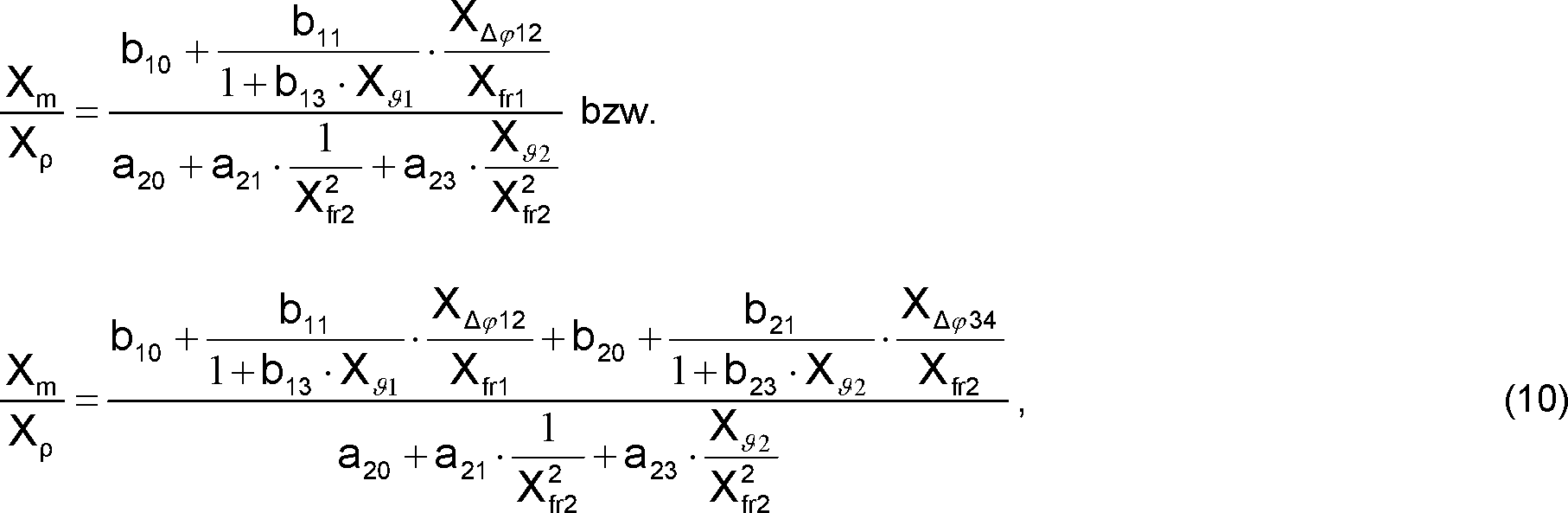
Nach einer weiteren Ausgestaltung der Erfindung umfaßt das Meßsystem ferner wenigstens einen an die Meß- und Betriebselektronik elektrisch angeschlossenen Verformungssensor D1 zum Erfassen einer – beispielsweise thermisch bedingten und/oder durch via Rohrleitung in das Meßsystem eingetragene Krafteinwirkung bewirkten – elastischen Verformung des ersten Vibrationselements V1. Der Verformungssensor D1 ist hierbei insbesondere dafür eingerichtet, zusammen mit der Meß- und Betriebselektronik ein von vorgenannter Verformung des Vibrationselements V1 abhängiges Verformungssignal d1 zu generieren und der Meß- und Betriebselektronik zu Verfügung zu stellen. Der Verformungssensor D1 kann beispielsweise mittels eines auf das Vibrationselement V1, nämlich auf einer dessen Lumen abgewandter Seite, aufgeklebten Dehnungsmeßstreifens (DMS) gebildet sein, der mit der Meß- und Betriebselektronik elektrisch verbunden ist, beispielsweise jeweils mittels eines – hier aus Gründen besserer Übersichtlichkeit ebenfalls nicht gezeigten – weiteren Paares von Anschlußdrähten. Das mittels des Verformungssensors D1 generierte Verformungssignal d1 kann von der Meß- und Betriebselektronik beispielsweise dafür genutzt werden, um Einflüsse der vorgenannten elastischen Verformungen des Vibrationselements V1 auf dessen Schwingungseigenschaften bzw. damit einhergehende Verfälschungen etwa der Phasendifferenz Δφ12 entsprechend zu korrigieren. Daher ist die Meß- und Betriebselektronik nach einer weiteren Ausgestaltung der Erfindung dafür eingerichtet, den die Volumendurchflußrate repräsentierenden Meßwert Xv und/oder den den Volumendurchfluß repräsentierenden Meßwert XV mittels des Verformungssignals zu generieren bzw. als gültigen Meßwert X(XV → X, Xv → X) des Meßsystems auszugeben. Das Verformungssignal d1 kann – alternativ oder in Ergänzung – aber auch dafür dienen, mittels der Meß- und Betriebselektronik zu detektieren, ob das Vibrationselement V1 momentan keine elastischen Verformung der vorgenannten Art aufweist, so daß also auch dessen momentane Resonanzfrequenz fr1 als eine genaues Maß für die Dichte des Mediums gut geeignet ist, mithin die Volumendurchflußrate repräsentierende Meßwerte Xv bzw. den Volumendurchfluß repräsentierende Meßwerte XV momentan auch basierend auf der Signalfrequenz des ersten und/oder zweiten Schwingungssignals ermittel- und ggf. als gültige Meßwerte X des Meßsystems ausgebbar sind, oder aber ob das Vibrationselement V1 in einem solch hohen Maße deformiert ist, daß dessen Resonanzfrequenz fr1 momentan kein ausreichend genaues Maß für die momentane Dichte des Mediums sein kann, mithin die Volumendurchflußrate repräsentierende Meßwerte Xv bzw. den Volumendurchfluß repräsentierende Meßwerte XV vernünftigerweise basierend auf der Signalfrequenz des dritten Schwingungssignal s3 zu ermitteln sind.According to a further embodiment of the invention, the measuring system further comprises at least one of the measuring and operating electronics electrically connected deformation sensor D1 for detecting a - for example, thermally induced and / or introduced via the pipe into the measuring system force effect - elastic deformation of the first vibrating element V1. In this case, the deformation sensor D1 is set up in particular to generate, together with the measuring and operating electronics, a deformation signal d1 dependent on the aforementioned deformation of the vibration element V1 and to provide the measuring and operating electronics. The deformation sensor D1 can be formed, for example, by means of a strain gauge (DMS) glued to the vibration element V1, namely on one side of the lumen thereof, which is electrically connected to the measuring and operating electronics, for example each by means of one - here also for better clarity not shown - another pair of leads. The deformation signal d1 generated by means of the deformation sensor D1 can be used by the measuring and operating electronics, for example, to influence the aforementioned elastic Deformations of the vibrating element V1 on the vibration characteristics or associated distortions about the phase difference Δφ 12 to correct accordingly. Therefore, the measuring and operating electronics according to a further embodiment of the invention is adapted to generate the volume flow rate representative of the measured value X v and / or the volume flow representing measured value X V by means of the deformation signal or as a valid measured value X (X V → X, X v → X) of the measuring system. The deformation signal d1 can - alternatively or in addition - but also serve to detect by means of the measuring and operating electronics, whether the vibrating element V1 currently has no elastic deformation of the aforementioned type, so that therefore its instantaneous resonant frequency f r1 as an accurate measure is well suited for the density of the medium, thus measuring values X v representing the volume flow rate or measured values X V currently also being determined based on the signal frequency of the first and / or second oscillation signal and possibly outputable as valid measured values X of the measuring system , or whether the vibrating element V1 is deformed to such an extent that its resonant frequency f r1 can not be a sufficiently accurate measure of the instantaneous density of the medium, thus the measured values X v representing the volumetric flow rate or the measured values X V representing the volumetric flow rate vernün ft are based on the signal frequency of the third vibration signal s3 to determine.
Das erfindungsgemäße Meßsystem kann ferner auch zumindest zwei unterschiedliche, beispielsweise mittels des vorgenannten Verformungssignal d1 selektiv aktivierbare, Betriebsmoden für die die Ermittlung der Volumendurchflußrate bzw. des Volumendurchflusses des in der Rohrleitung strömenden Mediums aufweisen, nämlichen einen ersten Betriebsmode, in dem die Meß- und Betriebselektronik die als gültige Meßwerte X des Meßsystems dienenden Meßwerte XV(XV → X) bzw. Xv(Xv → X) basierend sowohl auf der Phasendifferenz Δφ12 als auch auf der der Resonanzfrequenz fr2 des Vibrationselements V2 entsprechenden Signalfrequenz des dritten Schwingungssignals s3 ermittelt, und einen alternativen zweiten Betriebsmode, in dem die Meß- und Betriebselektronik die als gültige Meßwerte X des Meßsystems dienenden Meßwerte XV bzw. Xv basierend sowohl auf der Phasendifferenz Δφ12 als auch auf der der Resonanzfrequenz fr1 des Vibrationselements V1 entsprechenden Signalfrequenz des ersten und/oder zweiten Schwingungssignals, nicht aber basierend auf der Resonanzfrequenz fr2 des Vibrationselements V2 bzw. der dieser entsprechenden Signalfrequenz des Schwingungssignals s3 ermittelt. Die Meß- und Betriebselektronik kann hierbei ferner auch so eingerichtet sein, daß sie das dem Anregen des Vibrationselemets V2 dienende Treibersignal e2 im zweiten Betriebsmode des Meßsystems nicht bzw. lediglich im ersten Betriebsmode des Meßsystems liefert, mithin das Vibrationselement V2 im zweiten Betriebsmode nicht bzw. lediglich im ersten Betriebsmode vibrieren gelassen ist. Die Aktivierung des ersten bzw. zweiten Betriebsmodes wiederum kann beispielsweise jeweils basierend auf dem Verformungssignal d1 erfolgen, etwa mittels eines wiederkehrend in der Meß- und Betriebselektronik ausgeführten Vergleichs einer (momentanen) Amplitude des Verformungssignals d1 mit einer als Schaltschwelle für die Deaktivierung des ersten und die Aktivierung des zweiten Betriebsmodes dienenden, meßsystemspezifischen ersten Deformationsreferenzwerts, der einen vorgegebenen ersten Deformationsgrad zumindest des Vibrationselements V1 repräsentiert, bzw. mittels eines wiederkehrend in der Meß- und Betriebselektronik ausgeführten Vergleichs vorgenannter Amplitude des Verformungssignals d1 mit einer als Schaltschwelle für die Deaktivierung des zweiten und die Aktivierung des ersten Betriebsmodes dienenden, meßsystemspezifischen zweiten Deformationsreferenzwerts, der einen vorgegebenen zweiten, nämlich im Vergleich zum ersten Deformationsgrad kleineren, Deformationsgrad Vibrationselements V1 repräsentiert. Alternativ oder in Ergänzung kann die Aktivierung des ersten und/oder zweiten Betriebsmodes jeweils unter Verwendung auch des erwähnten ersten Temperatursignals θ1 erfolgen, beispielsweise derart, daß in der Meß- und Betriebselektronik wiederkehrend ein Vergleich einer (momentanen) Amplitude des Temperatursignals θ1 mit einer als Schaltschwelle für die Deaktivierung des ersten und die Aktivierung des zweiten Betriebsmodes dienenden, meßsystemspezifischen ersten Temperaturreferenzwerts ausgeführt wird, der eine für das Vibrationselements V1 vorgegebenen erste Wärmespannung repräsentiert, bzw. in der Meß- und Betriebselektronik wiederkehrend ein Vergleich vorgenannter Amplitude des Temperatursignals θ1 mit einer als Schaltschwelle für die Deaktivierung des zweiten und die Aktivierung des ersten Betriebsmodes dienenden, meßsystemspezifischen zweiten Temperaturreferenzwerts ausgeführt wird, der einen vorgegebenen zweite, nämlich im Vergleich zur ersten Wärmespannung geringere, Wärmespannung im Vibrationselements V1 repräsentiert. Für den Fall, daß die Aktivierung des ersten Betriebsmodes sowohl basierend auf dem Verformungssignal d1 als auch dem Temperatursignal θ1 erfolgt, ist die Meß- und Betriebelektonik in vorteilhafter Weise so eingerichtet, daß nämlicher erster Betriebsmodes auch bereits dann aktiviert wird, wenn ein Erreichen bzw. Überschreiten lediglich des ersten Deformationsreferenzwerts durch das Verformungssignal d1 oder auch nur des ersten Temperaturreferenzwerts durch das Temperatursignal θ1 detektiert ist. Umgekehrt ist für den Fall, daß die Aktivierung des zweiten Betriebsmodes sowohl basierend auf dem Verformungssignal d1 als auch dem Temperatursignal θ1 erfolgt, die Meß- und Betriebelektonik in vorteilhafter Weise so eingerichtet, daß nämlicher zweiter Betriebsmodes erst dann aktiviert wird, wenn ein Erreichen bzw. Unterschreiten sowohl des zweiten Deformationsreferenzwerts durch das Verformungssignal d1 als auch des zweiten Temperaturreferenzwerts durch das Temperatursignal θ1 detektiert ist. In Ergänzung zur vorbeschrieben selektiven Aktivierung/Deaktivierung des ersten bzw. Betriebsmoden basierend auf dem Temperatursignal θ1 kann es ferner, nicht zuletzt für das Erreichen einer hohen Meßgenauigkeit auch bei der Ermittlung der Volumendurchflußrate bzw. des Volumendurchflusses bei relativ hohen, nämlich oberhalb einer, beispielsweise 8 m/s (Meter pro Sekunde) oder mehr betragenden, meßsystemspezifischen kritischen Strömungsgeschwindigkeit liegenden, Strömungsgeschwindigkeiten, durchaus von Vorteil sein, auch dann vom zweiten in den ersten Betriebsmode zu wechseln, mithin den ersten Betriebsmode auch dann zu aktivieren, wenn ein Phasendifferenz-zu-Signalfrequenz-Verhältnis – nämlich ein Verhältnis der momentan gemessenen Phasendifferenz Δφ12 zur der momentanen Resonanzfrequenz fr1 entsprechenden Signalfrequenz wenigstens eines der Sensorsignale s1, s2 – einen dafür vorgegebenen, nämliche meßsystemspezifische kritische Strömungsgeschwindigkeit repräsentierenden Referenzwert erreicht oder überschreitet.The measuring system according to the invention can also have at least two different, for example by means of the aforementioned deformation signal d1 selectively activatable, operating modes for determining the Volumendurchflußrate or the volume flow of the medium flowing in the pipe, namely a first operating mode in which the measuring and operating electronics the measured values X V (X V → X) and X v (X v → X) serving as valid measured values X of the measuring system are based both on the phase difference Δφ 12 and on the signal frequency of the third oscillation signal corresponding to the resonant frequency f r2 of the vibrating element V2 s3, and an alternative second mode of operation in which the measuring and operating electronics corresponding to the measured values X V and X v serving as valid measured values X of the measuring system based both on the phase difference Δφ 12 and on the resonant frequency f r1 of the vibrating element V1 Signal frequency d it determines the first and / or second oscillation signal, but not based on the resonant frequency f r2 of the vibrating element V2 or the corresponding signal frequency of the oscillation signal s3. In this case, the measuring and operating electronics can also be set up so that they do not supply the driving signal e2 serving to excite the vibration element V2 in the second operating mode of the measuring system or only in the first operating mode of the measuring system, ie the vibrating element V2 in the second operating mode does not or is vibrated only in the first operating mode. The activation of the first or second operating mode, in turn, can in each case take place, for example, based on the deformation signal d1, for example by means of a comparison of a (momentary) amplitude of the deformation signal d1 with a switching frequency for the deactivation of the first and that carried out recurrently in the measuring and operating electronics Activation of the second operating mode serving, measuring system-specific first deformation reference value representing a predetermined first degree of deformation of at least the vibrating element V1, or by means of a recurring executed in the measuring and operating electronics comparison of the aforementioned amplitude of the deformation signal d1 with a threshold for deactivating the second and the Activation of the first operating mode serving, measuring system-specific second deformation reference value, the predetermined second, namely smaller compared to the first degree of deformation, degree of deformation Vibr representionsions V1 represents. Alternatively or in addition, the activation of the first and / or second operating mode in each case using the mentioned first temperature signal θ1, for example, such that in the measuring and operating electronics a comparison of a (current) amplitude of the temperature signal θ1 with a switching threshold for the deactivation of the first and the activation of the second operating mode serving, measuring system specific first temperature reference value is represented, which represents a predetermined for the vibrating element V1 first thermal voltage, or in the measuring and operating electronics a recurring comparison of the aforementioned amplitude of the temperature signal θ1 with a switching threshold for the deactivation of the second and the activation of the first operating mode serving, measuring system-specific second temperature reference value is executed, the geri a predetermined second, namely compared to the first thermal More, thermal stress in the vibrating element V1 represents. In the event that the activation of the first operating mode takes place both on the basis of the deformation signal d1 and the temperature signal θ1, the measuring and operating electronics are advantageously arranged so that the same first operating mode is already activated when a Exceeding only the first deformation reference value by the deformation signal d1 or even only the first temperature reference value is detected by the temperature signal θ1. Conversely, in the event that the activation of the second operating mode takes place both on the basis of the deformation signal d1 and the temperature signal θ1, the measuring and operating electronics are advantageously arranged so that the same second operating mode is activated only when a Fall below both the second Deformation reference value is detected by the deformation signal d1 and the second temperature reference value by the temperature signal θ1. In addition to the above-described selective activation / deactivation of the first or operating modes based on the temperature signal θ1, it can also, not least for achieving a high measurement accuracy in the determination of the volume flow rate or the volume flow at relatively high, namely above one, for example 8th m / s (meters per second) or more, measuring system specific critical flow velocity lying flow velocities, be quite advantageous to change then from the second to the first operating mode, and thus to activate the first operating mode, even if a phase difference Signal frequency ratio - namely a ratio of the momentarily measured phase difference Δφ 12 to the instantaneous resonant frequency f r1 corresponding signal frequency at least one of the sensor signals s1, s2 - represent a prescribed for this same measuring system specific critical flow velocity reaches or exceeds the relevant reference value.
Nach einer weiteren Ausgestaltung weist das Meßsystem ferner einen dritten Betriebsmode auf, in dem die Meß- und Betriebselektronik die als gültige Meßwerte X des Meßsystems dienenden Meßwerte XV(XV → X) bzw. Xv(Xv → X) zwar basierend sowohl auf der Phasendifferenz Δφ12 als auch auf der der Resonanzfrequenz fr1 des Vibrationselements V1 entsprechenden Signalfrequenz zumindest eines der Schwingungssignale s1, s2 ermittelt, im Unterschied zum vorbeschriebene zweiten Betriebsmode gleichzeitig aber auch das Vibrationselement V2 vom Medium kontaktiert ist und währendessen mittels des von der Meß- und Betriebselektronik im dritten Betriebsmode zumindest zeitweise ebenfalls genierten Treibersignals e2 entsprechend aktiv zu Resonanzschwingungen angeregt ist. Die Meß- und Betriebselektronik ist hierbei ferner dafür eingerichtet, basierend sowohl auf der der Resonanzfrequenz fr1 entsprechenden Signalfrequenz zumindest eines der während des dritten Betriebsmodes empfangenen Schwingungssignale s1, s2 als auch der der Resonanzfrequenz fr2 entsprechenden Signalfrequenz zumindest des während des dritten Betriebsmodes empfangenen Schwingungssignals s3 eine (Selbst-)Überprüfung des Meßsystems durchzuführen, insb. dahingehend, ob das Meßsystem nach wie vor innerhalb der dafür vorgegeben Spezifikation arbeitet, und/oder ob die vom Meßsystem ausgegebenen Meßwerte X als valide angesehen werden können. Die Überprüfung des Meßsystems kann z.B. durchgeführt werden, indem mittels der Meß- und Betriebselektronik wiederkehrend eine – relative oder absolute – Abweichung beider Resonanzfrequenzen fr1, fr2 voneinander ermittelt, und hernach mit einem dafür entsprechend vorgegebenen Grenzwert verglichen wird, der eine maximal zulässige bzw. für ein intaktes Meßsystem maximal zu erwartende Abweichung beider Resonanzfrequenzen fr1, fr2 repräsentiert. Für den Fall, daß nämliche Abweichung den vorgenannten Grenzwert erreicht oder überschreitet kann die Meß- und Betriebselektronik ferner beispielsweise einen Alarm generieren, der signalisiert, daß eine irreversible Beschädigung zumindest eines der beiden Vibrationselemente V1, V2, etwa infolge Abrasion, Korrosion, plastischer Deformierung oder Rißbildung, festgestellt ist. Alternativ oder in Ergänzung ist die Meß- und Betriebselektronik ferner dafür eingerichtet, die vorgenannte Überprüfung des Meßsystems basierend auf den während des dritten Betriebsmodes generierten Treibersignalen e1, e2, durchzuführen, beispielsweise derart, daß die Meß- und Betriebselektronik während des dritten Betriebsmodes für jedes der beiden Treibersignale e1, e2 jeweils eine mittlere elektrische Leistung, nämlich eine mittlere elektrische Leistung Pexc1 des Treibersignals e1 und eine mittlere elektrische Leistung Pexc2 des Treibersignals e2, ermittelt und eine – relative oder absolute – Abweichung beider elektrischen Leistungen Pexc1, Pexc2 voneinander mit einem dafür entsprechend vorgegebenen Grenzwert vergleicht. Auch hierbei kann der Grenzwert so gesetzt sein, daß ein Erreichen oder Überschreiten desselben eine, ggf. wiederum zu alarmierende irreversible Beschädigung zumindest eines der beiden Vibrationselemente V1, V2 indiziert. Alternativ oder in Ergänzung zur vorbeschrieben Überprüfung des Meßsystems mittels der im dritten Betriebsmode generierten Schwingungs- und/oder Treibersignale können zudem auch die beiden erwähnten Temperatursignale θ1, θ2 zur Überprüfung des Meßsystems verwendet werde, beispielsweise derart, daß für den Fall, daß beide Vibrationselementen V1, V2 nominell vom gleichen Medium kontaktiert sind bzw. sein müßten, bei einer basierend auf beiden Temperatursignalen θ1, θ2 ermittelten unzulässig hohen und/oder unzulässig lang andauernden Abweichung der beiden Temperaturen ϑ1, ϑ2 voneinander, mittels der Meß- und Betriebselektronik ein Alarm generiert wird, der eine Bildung eines Belags auf zumindest einem der beiden Vibrationselemente V1, V2 signalisiert, und/oder ein Alarm generiert wird, der signalisiert, daß zumindest eines der das Vibrationselement V1 oder der das Vibrationselement V2 bildenden Meßrohre zumindest teilweise verstopft ist.According to a further embodiment, the measuring system further comprises a third operating mode in which the measuring and operating electronics based both the measured values X V (X V → X) and X v (X v → X) serving as valid measured values X of the measuring system on the phase difference Δφ 12 as well as on the resonant frequency f r1 of the vibrating element V1 corresponding signal frequency at least one of the vibration signals s1, s2 determined, in contrast to the above-described second mode simultaneously but also the vibrating element V2 is contacted by the medium and while eating by means of the of the Meß - And operating electronics in the third operating mode at least temporarily also genierten driver signal e2 is actively excited accordingly to resonant vibrations. The measuring and operating electronics here are further adapted, based both on the resonant frequency f r1 corresponding signal frequency at least one of the received during the third operating mode vibration signals s1, s2 and the resonant frequency f r2 corresponding signal frequency at least of the received during the third operating mode vibration signal s3 to carry out a (self-) check of the measuring system, in particular as to whether the measuring system still operates within the specified specification, and / or whether the measured values X output by the measuring system can be regarded as valid. The verification of the measuring system can be carried out, for example, by using the measuring and operating electronics recurrently a - relative or absolute - deviation of both resonant frequencies f r1 , f r2 determined from each other, and then compared with a correspondingly predetermined limit value, which is a maximum allowable or represents an expected maximum deviation of both resonant frequencies f r1 , f r2 for an intact measuring system. In the event that the same deviation reaches or exceeds the aforementioned limit value, the measuring and operating electronics can further generate, for example, an alarm which signals that irreversible damage to at least one of the two vibrating elements V1, V2, for example as a result of abrasion, corrosion, plastic deformation or Cracking, is found. Alternatively or in addition, the measuring and operating electronics is further configured to perform the aforementioned check of the measuring system based on the generated during the third operating mode driver signals e1, e2, for example, such that the measuring and operating electronics during the third operating mode for each of the two driver signals e1, e2 each have a mean electrical power, namely a mean electric power P exc1 of the drive signal e1 and a mean electric power P exc2 of the drive signal e2, and a - relative or absolute - deviation of the two electrical powers P exc1 , P exc2 from each other compared with a correspondingly predetermined limit value. Again, the limit can be set so that reaching or exceeding the same one, possibly in turn alarming irreversible damage to at least one of the two vibration elements V1, V2 indicated. Alternatively or in addition to the above-described review of the measuring system by means of the vibration and / or driver signals generated in the third operating mode also the two mentioned temperature signals θ1, θ2 be used to check the measuring system, for example, such that in the event that both vibrating elements V1 , V2 are nominally contacted by the same medium or should be, with an excessively high and / or impermissibly long lasting deviation of the two temperatures θ1, θ2 determined from both temperature signals θ1, θ2, an alarm is generated by the measuring and operating electronics , which signals a formation of a deposit on at least one of the two vibration elements V1, V2, and / or an alarm is generated, which signals that at least one of the vibration element V1 or the vibration element V2 forming measuring tubes is at least partially blocked.
Zum Steuern der Strömung durch das Vibrationselement V2 bzw. der Massendurchflußrate m2, ggf. auch zwecks eines vorübergehenden Vermeidens jeglicher Strömung durch das Vibrationselement V2 und/oder zwecks des kontrollierten Beförderns des durch Vibrationselement V2 strömende Teilvolumens, beispielsweise im Falle eines hochviskosen Mediums von mehr als 100 mPa·s (Millipascalsekunde) und/oder einer gelegentlich relativ niedrigen Massendurchflußrate m1 von weniger als 50% eines für die Massendurchflußrate m1 vorgegebenen meßsystemspezifischen Maximalwerts und/oder beispielsweise auch um den Strömungsquerschnitt des Vibrationselements V2, mithin dessen Einbaumaße möglichst klein halten zu können, insb. auch so klein, daß im Ergebnis beide Vibrationselemente V1, V2 in ein ansonsten auch in herkömmlichen Meßsystemen mit nur einem einzigen Vibrationselement üblicherweise verwendeten Gehäuse passen, und/oder zum Begrenzen der Massendurchflußrate m2 auf einen dafür vorgegebenen Maximalwert, beispielsweise auch im Falle hoher Massendurchflußraten m1 von mehr als 80% des dafür vorgegebenen meßsystemspezifischen Maximalwerts, umfaßt das Meßsystem gemäß einer weiteren Ausgestaltung ferner ein zum einen an einer der Strömungsöffnungen Oii,1, Oii,2 zweiter Art und zum anderen an das Vibrationselement V2 angeschlossene, beispielsweise ein elektromagnetisch betätigbares Ventil und/oder eine elektromotorisch betriebene Pumpe aufweisende, Fluidkontrolleinrichtung FC. Die Fluidkontrolleinrichtung FC kann beispielsweise mittels separater, ggf. innerhalb des Gehäuses verteilt angeordneten und mittels entsprechender fluidischer bzw. elektrischer Anschlußleitungen miteinander verbundenen, Einzelkomponenten gebildet oder beispielsweise als ein sämtliche Einzelkomponenten in einem Modul vereinigender Durchfluß-Kontroller ausgebildet sein. Nach einer weiteren Ausgestaltung der Erfindung ist die Fluidkontrolleinrichtung über eine der Anschlußleitungen L21, L22 strömungstechnisch mit einer der Strömungsöffnungen Oii,1, Oii,2 zweiter Art verbunden und/oder ist die Fluidkontrolleinrichtung mittels einer der Anschlußleitungen L21, L22 strömungstechnisch an das Vibrationselement V2 angeschlossen. Die Fluidkontrolleinrichtung FC bzw. die enthaltenen Ventile und/oder Pumpen können zudem beispielsweise mittels Anschlußdrähten mit der Meß- und Betriebselektronik elektrisch verbunden sein und von dieser im Betrieb des Meßsystem mittels entsprechender elektrischer Steuersignale fc1 direkt angesteuert und mit elektrischer Energie versorgt werden. Alternativ oder in Ergänzung kann die Fluidkontrolleinrichtung FC selbst eine eigene interne Steuerelektronik aufweisen, die eine von der Meß- und Betriebselektronik aus gespeisten eigenen Energieversorgungsschaltung umfaßt, und die von der Meß- und Betriebselektronik aus mittels entsprechender, von einem, beispielsweise binären, Steuersignal fc1 übertragenen Steuerkommandos gestartet bzw. gestoppt und/oder parametriert wird. Nach einer weiteren Ausgestaltung der Erfindung ist die Fluidkontrolleinrichtung oder sind die Meß- und Betriebselektronik und Fluidkontrolleinrichtung FC zusammen dafür eingerichtet, das durch das Vibrationselment V2 strömende Teilvolumen mit einer vorgebbaren Volumendurchflußrate strömen zu lassen bzw. nämliche Volumendurchflußrate auf einen dafür vorgegebenen, beispielsweise einem für die Messung der Resonanzfrequenz fr2 des Vibrationselements V2 besonders geeigneten Arbeitspunkt entsprechenden, Konstantwert zu regeln. Dies ermöglicht es zum einen allfällige Ungenauigkeit bei einer Bilanzierung der beiden Massendurchflußraten m1, m2 grundsätzlich zu minimieren und zum andere kann damit sehr einfach eine für Ermittlung hochgenauer Meßwert Xv und/oder Meßwert XV, mithin für die Messung der Volumendurchflußrate bzw. des Volumendurchflusses, besonders geeignete Massendurchflußrate m2 des durch Vibrationselment V2 strömenden Teilvolumen unabhängig von andern Prozeßparametern, wie etwa einer Viskosität, einer Temperatur, einem Druck und/oder einer Massendurchflußrate des in der Rohrleitung strömenden Mediums eingestellt bzw. nämlichen Prozeßparametern entsprechend angepaßt werden. Alternativ oder in Ergänzung dazu, kann für den oben beschriebenen Fall, daß das Meßsystem zumindest zwei Betriebsmoden für die die Ermittlung der Volumendurchflußrate bzw. des Volumendurchflusses des in der Rohrleitung strömenden Mediums aufweist, die Fluidkontrolleinrichtung FC während des erwähnten zweiten Betriebsmodes deaktiviert ist, derart, daß eine allfällig in der Fluidkontrolleinrichtung vorgesehene Pumpe abgeschaltet und/oder ein allfällig in der Fluidkontrolleinrichtung vorgesehenes Ventil geschlossen ist, bzw. daß die Fluidkontrolleinrichtung FC lediglich während des erwähnten ersten Betriebsmodes aktiviert ist, derart, daß eine allfällig in der Fluidkontrolleinrichtung vorgesehene Pumpe angeschaltet und/oder ein allfällig in der Fluidkontrolleinrichtung vorgesehenes Ventil zumindest teilweise geöffnet ist.For controlling the flow through the vibrating element V2 or the mass flow rate m 2 , if necessary also for the purpose of temporarily avoiding any flow through the vibrating element V2 and / or for the purpose of conveying the part volume flowing through the vibrating element V2 in a controlled manner, for example in the case of a highly viscous medium of more as 100 mPa · s (millipascal second) and / or an occasionally relatively low mass flow rate m 1 of less than 50% of a measuring system specific maximum value given for the mass flow rate m 1 and / or for example also around the Flow cross-section of the vibrating element V2, thus to be able to keep its installation dimensions as small as possible, esp. Also so small that both vibrating elements V1, V2 fit into a housing otherwise commonly used in conventional measuring systems with only a single vibrating element, and / or limiting the mass flow rate m 2 to a predetermined maximum value, for example, even in the case of high mass flow rates m 1 of more than 80% of the predetermined measuring system specific maximum value, the measuring system according to another embodiment further comprises a on one of the flow openings O ii, 1 , O. ii, 2 second type and on the other hand to the vibrating element V2 connected, for example, an electromagnetically operable valve and / or an electric motor driven pump having, fluid control FC. The fluid control device FC can be formed for example by means of separate, optionally distributed within the housing and interconnected by means of corresponding fluidic or electrical connection lines, individual components formed or, for example, as a all individual components in a module unifying flow controller. According to a further embodiment of the invention, the fluid control device via one of the connecting lines L21, L22 fluidly connected to one of the flow openings O ii, 1 , O ii, 2 second type and / or the fluid control device by means of one of the connecting lines L21, L22 fluidly to the vibrating element V2 connected. The fluid control device FC or the valves and / or pumps contained can also be electrically connected, for example, by means of connecting wires with the measuring and operating electronics and be directly controlled by this during operation of the measuring system by means of corresponding electrical control signals fc1 and supplied with electrical energy. Alternatively or in addition, the fluid control device FC itself may have its own internal control electronics, which comprises a powered by the measuring and operating electronics own power supply circuit, and from the measuring and operating electronics by means of appropriate, one, for example binary, control signal fc1 transmitted Control command started or stopped and / or parameterized. According to a further embodiment of the invention, the fluid control device or the measuring and operating electronics and fluid control FC together are adapted to let flow through the Vibrationselment V2 partial volume with a predetermined volumetric flow rate or the same volume flow rate to a given, for example one for the Measurement of the resonant frequency f r2 of the vibrating element V2 particularly suitable operating point corresponding, constant value to regulate. This makes it possible, on the one hand, to minimize any inaccuracies in the balancing of the two mass flow rates m 1 , m 2 and, on the other hand, can very easily determine a highly accurate measured value X v and / or measured value X v , and thus for measuring the volumetric flow rate. the volumetric flow, particularly suitable mass flow rate m 2 of the Teilvolumen flowing through Vibrationselment V2 regardless of other process parameters, such as a viscosity, a temperature, a pressure and / or a mass flow rate of the flowing medium in the pipeline or the same process parameters are adjusted accordingly. Alternatively or in addition, in the case described above, the measuring system may have at least two operating modes for determining the volume flow rate or volume flow of the medium flowing in the pipeline, the fluid control device FC being deactivated during said second mode of operation. that any pump provided in the fluid control device is switched off and / or a valve provided in the fluid control device is closed, or that the fluid control device FC is activated only during said first operating mode such that a pump provided in the fluid control device is switched on and / or or any valve provided in the fluid control device is at least partially opened.
In der
ZITATE ENTHALTEN IN DER BESCHREIBUNG QUOTES INCLUDE IN THE DESCRIPTION
Diese Liste der vom Anmelder aufgeführten Dokumente wurde automatisiert erzeugt und ist ausschließlich zur besseren Information des Lesers aufgenommen. Die Liste ist nicht Bestandteil der deutschen Patent- bzw. Gebrauchsmusteranmeldung. Das DPMA übernimmt keinerlei Haftung für etwaige Fehler oder Auslassungen.This list of the documents listed by the applicant has been generated automatically and is included solely for the better information of the reader. The list is not part of the German patent or utility model application. The DPMA assumes no liability for any errors or omissions.
Zitierte PatentliteraturCited patent literature
- CN 101858765 A [0002, 0075] CN 101858765 A [0002, 0075]
- EP 1001254 A [0002] EP 1001254A [0002]
- EP 816807 A [0002] EP 816807 A [0002]
- EP 553939 A [0002] EP 553939A [0002]
- US 2002/0157479 A [0002] US 2002/0157479 A [0002]
- US 2006/0150750 A [0002] US 2006/0150750 A [0002]
- US 2006/0162468 A [0002, 0063] US 2006/0162468 A [0002, 0063]
- US 2007/0151368 A [0002, 0003, 0063] US 2007/0151368 A [0002, 0003, 0063]
- US 2008/0047361 A [0002, 0063] US 2008/0047361 A [0002, 0063]
- US 2010/0242623 A [0002, 0065, 0065] US 2010/0242623 A [0002, 0065, 0065]
- US 2011/0016991 A [0002, 0063] US 2011/0016991 A [0002, 0063]
- US 2011/0146416 A [0002, 0003, 0003, 0004, 0004, 0004, 0004, 0011] US 2011/0146416 A [0002, 0003, 0003, 0004, 0004, 0004, 0004, 0011]
- US 2011/0154914 A [0002, 0063] US 2011/0154914 A [0002, 0063]
- US 2011/0265580 A [0002, 0003, 0004, 0004, 0010] US 2011/0265580 A [0002, 0003, 0004, 0004, 0010]
- US 2011/0113896 [0002] US 2011/0113896 [0002]
- US 2012/0048034 A [0002, 0063] US 2012/0048034 A [0002, 0063]
- US 2012/0073384 A [0002, 0011, 0011, 0011] US 2012/0073384 A [0002, 0011, 0011, 0011]
- US 2012/0079891 A [0002, 0011, 0065, 0065] US 2012/0079891 A [0002, 0011, 0065, 0065]
- US 2012/0090407 A [0002] US 2012/0090407 A [0002]
- US 2012/0109543 A [0002] US 2012/0109543 A [0002]
- US 2012/0167697 A [0002] US 2012/0167697 A [0002]
- US 4777833 A [0002, 0060] US 4777833 A [0002, 0060]
- US 4793191 A [0002] US 4793191 A [0002]
- US 4801897 A [0002, 0060, 0060] US 4801897 A [0002, 0060, 0060]
- US 4823614 A [0002, 0011] US 4823614 A [0002, 0011]
- US 4879911 A [0002, 0060] US 4879911 A [0002, 0060]
- US 5009109 A [0002, 0060] US 5009109 A [0002, 0060]
- US 5024104 A [0002, 0060] US 5024104 A [0002, 0060]
- US 5050439 A [0002, 0060] US 5050439 A [0002, 0060]
- US 5370002 A [0002] US 5370002 A [0002]
- US 5796011 A [0002, 0003, 0008, 0075] US 5796011 A [0002, 0003, 0008, 0075]
- US 5804741 A [0002, 0060] US 5804741 A [0002, 0060]
- US 6311136 A [0002, 0060] US 6311136 A [0002, 0060]
- US 6308580 A [0002] US 6308580 A [0002]
- US 6311136 B [0002, 0008] US 6311136 B [0002, 0008]
- US 6415668 B [0002] US 6415668 B [0002]
- US 6711958 B [0002, 0075] US 6711958 B [0002, 0075]
- US 6920798 B [0002] US 6920798 B [0002]
- US 7134347 B [0002] US 7134347 B [0002]
- US 7392709 B [0002] US 7392709 B [0002]
- US 7992452 B [0002] US 7992452 B [0002]
- WO 00/57141 A [0002, 0075] WO 00/57141 A [0002, 0075]
- WO 01/067052 A [0002] WO 01/067052 A [0002]
- WO 03/027616 A [0002] WO 03/027616 A [0002]
- WO 2008/039203 A [0002] WO 2008/039203 A [0002]
- WO 2011/008307 A [0002] WO 2011/008307 A [0002]
- WO 2011/008308 A [0002] WO 2011/008308 A [0002]
- WO 2011/019344 A [0002] WO 2011/019344 A [0002]
- WO 2011/068500 A [0002] WO 2011/068500 A [0002]
- WO 2012/028425 A [0002, 0011] WO 2012/028425 A [0002, 0011]
- WO 90/15309 A [0002] WO 90/15309 A [0002]
- WO 90/15310 A [0002] WO 90/15310 A [0002]
- WO 94/21999 A [0002] WO 94/21999 A [0002]
- WO 96/05484 A [0002] WO 96/05484 A [0002]
- WO 97/33150 A [0002] WO 97/33150 A [0002]
- WO 98/038479 A [0002] WO 98/038479 A [0002]
- DE 102011089808 [0002] DE 102011089808 [0002]
- US 7350421 B [0003] US 7350421 B [0003]
- WO 01/29519 A [0008] WO 01/29519 A [0008]
- US 2012/0227512 A [0011] US 2012/0227512 A [0011]
- US 2010/0050783 A [0065, 0065] US 2010/0050783 A [0065, 0065]
- US 2010/0043569 A [0075] US 2010/0043569 A [0075]
- US 7921737 B [0075] US 7921737 B [0075]
- US 7823445 B [0075] US 7823445 B [0075]
- US 7437912 B [0075] US 7437912 B [0075]
- US 6477901 B [0075] US Pat. No. 6,477,901 B [0075]
- WO 2007/147786 A [0075] WO 2007/147786 A [0075]
- EP 564682 A [0090] EP 564682A [0090]
- US 6845663 B [0090] US 6845663 B [0090]
Zitierte Nicht-PatentliteraturCited non-patent literature
- http://www.us.endress.com/#products/~flowmeasurment-flowmeter-coriolis-masss [0060] http://www.us.endress.com/#products/~flowmeasurment-flowmeter-coriolis-masss [0060]
- http://www.us.endress.com/#product/FTL50 [0090] http://www.us.endress.com/#product/FTL50 [0090]
- http://www.us.endress.com/#product/FML621 [0090] http://www.us.endress.com/#product/FML621 [0090]
Claims (27)
Priority Applications (5)
| Application Number | Priority Date | Filing Date | Title |
|---|---|---|---|
| DE201210109729 DE102012109729A1 (en) | 2012-10-12 | 2012-10-12 | Measuring system for determining volumetric flow during measuring interval of total flowed volume of flowing medium, particularly liquid or gas, has vibration element for guiding flowing portion of medium, where vibration element has lumen |
| EP13766052.8A EP2906915B1 (en) | 2012-10-11 | 2013-09-23 | Measuring system for determining a volume flow and/or a volume flow rate of a medium flowing in a pipe line |
| US14/435,184 US9372107B2 (en) | 2012-10-11 | 2013-09-23 | Measuring system for ascertaining a volume flow and/or a volume flow rate of a medium flowing in a pipeline |
| EP22154559.3A EP4016013A1 (en) | 2012-10-11 | 2013-09-23 | Measuring system for determining a volume flow and / or a volume flow rate of a medium flowing in a pipeline |
| PCT/EP2013/069672 WO2014056709A1 (en) | 2012-10-11 | 2013-09-23 | Measuring system for determining a volume flow and/or a volume flow rate of a medium flowing in a pipe line |
Applications Claiming Priority (1)
| Application Number | Priority Date | Filing Date | Title |
|---|---|---|---|
| DE201210109729 DE102012109729A1 (en) | 2012-10-12 | 2012-10-12 | Measuring system for determining volumetric flow during measuring interval of total flowed volume of flowing medium, particularly liquid or gas, has vibration element for guiding flowing portion of medium, where vibration element has lumen |
Publications (1)
| Publication Number | Publication Date |
|---|---|
| DE102012109729A1 true DE102012109729A1 (en) | 2014-05-15 |
Family
ID=50555620
Family Applications (1)
| Application Number | Title | Priority Date | Filing Date |
|---|---|---|---|
| DE201210109729 Pending DE102012109729A1 (en) | 2012-10-11 | 2012-10-12 | Measuring system for determining volumetric flow during measuring interval of total flowed volume of flowing medium, particularly liquid or gas, has vibration element for guiding flowing portion of medium, where vibration element has lumen |
Country Status (1)
| Country | Link |
|---|---|
| DE (1) | DE102012109729A1 (en) |
Cited By (6)
| Publication number | Priority date | Publication date | Assignee | Title |
|---|---|---|---|---|
| DE102015104931A1 (en) * | 2014-12-31 | 2016-06-30 | Endress + Hauser Flowtec Ag | Coriolis mass flowmeter with four curved measuring tubes |
| EP3196604A1 (en) * | 2016-01-20 | 2017-07-26 | Krohne Messtechnik GmbH | Method for operating a coriolis mass flow meter and related coriolis mass flow meter |
| DE102016007905A1 (en) * | 2016-06-30 | 2018-01-04 | Endress+Hauser Flowtec Ag | Method for operating a vibration-type sensor |
| DE102016112002A1 (en) * | 2016-06-30 | 2018-01-04 | Endress + Hauser Flowtec Ag | Method for determining a physical parameter of a compressible medium with a vibration-type sensor and sensor for carrying out such a method |
| DE102019009024A1 (en) * | 2019-12-30 | 2021-07-01 | Endress+Hauser Flowtec Ag | Vibronic measuring system |
| WO2021233644A1 (en) * | 2020-05-20 | 2021-11-25 | Endress+Hauser Flowtec Ag | Method for determining a density measurement value or a measurement value of a density-dependent measurand, and coriolis mass flowmeter for performing the method |
Citations (65)
| Publication number | Priority date | Publication date | Assignee | Title |
|---|---|---|---|---|
| US4777833A (en) | 1986-11-12 | 1988-10-18 | Micro Motion, Inc. | Ferromagnetic drive and velocity sensors for a coriolis mass flow rate meter |
| US4793191A (en) | 1986-09-26 | 1988-12-27 | Flowtec Ag | Mass flow meter operating by the cariolis principle |
| US4801897A (en) | 1986-09-26 | 1989-01-31 | Flowtec Ag | Arrangement for generating natural resonant oscillations of a mechanical oscillating system |
| US4823614A (en) | 1986-04-28 | 1989-04-25 | Dahlin Erik B | Coriolis-type mass flowmeter |
| US4879911A (en) | 1988-07-08 | 1989-11-14 | Micro Motion, Incorporated | Coriolis mass flow rate meter having four pulse harmonic rejection |
| WO1990015310A1 (en) | 1989-06-09 | 1990-12-13 | Micro Motion, Inc. | Improved stability coriolis mass flow meter |
| WO1990015309A1 (en) | 1989-06-02 | 1990-12-13 | Micro Motion, Inc. | Coriolis mass flow rate meter having a substantially increased noise immunity |
| US5009109A (en) | 1989-12-06 | 1991-04-23 | Micro Motion, Inc. | Flow tube drive circuit having a bursty output for use in a coriolis meter |
| US5024104A (en) | 1988-12-21 | 1991-06-18 | Schlumberger Industries Limited | Combined output and drive circuit for a mass flow transducer |
| US5050439A (en) | 1986-10-28 | 1991-09-24 | The Foxboro Company | Coriolis-type mass flowmeter circuitry |
| EP0553939A2 (en) | 1985-08-29 | 1993-08-04 | Micro Motion Incorporated | Coriolis flowmeter |
| EP0564682A1 (en) | 1992-04-09 | 1993-10-13 | Endress + Hauser Flowtec AG | Oscillating body arrangement for a mass flowmeter |
| WO1994021999A1 (en) | 1991-10-08 | 1994-09-29 | Micro Motion, Inc. | Vibrating tube densimeter |
| US5370002A (en) | 1993-07-23 | 1994-12-06 | Micro Motion, Inc. | Apparatus and method for reducing stress in the brace bar of a Coriolis effect mass flow meter |
| WO1996005484A1 (en) | 1994-08-12 | 1996-02-22 | Micro Motion, Inc. | Method and apparatus for fault detection and correction in coriolis effect mass flowmeters |
| WO1997033150A2 (en) | 1996-03-06 | 1997-09-12 | Micro Motion, Inc. | Coriolis viscometer using parallel connected coriolis mass flowmeters |
| EP0816807A2 (en) | 1996-03-11 | 1998-01-07 | The Foxboro Company | Method and apparatus for correcting for performance degrading factors in coriolistype mass flowmeter |
| US5796011A (en) | 1993-07-20 | 1998-08-18 | Endress + Hauser Flowtech Ag | Coriolis-type mass flow sensor |
| WO1998038479A1 (en) | 1997-02-27 | 1998-09-03 | Micro Motion, Inc. | Coriolis flowmeter having axially compliant case ends |
| US5804741A (en) | 1996-11-08 | 1998-09-08 | Schlumberger Industries, Inc. | Digital phase locked loop signal processing for coriolis mass flow meter |
| DE69505808T2 (en) * | 1994-04-26 | 1999-04-01 | Direct Measurement Corp | CORIOLIS MASS FLOW METER WITH ADJUSTABLE PRESSURE AND DENSITY SENSITIVITY |
| EP1001254A1 (en) | 1998-05-29 | 2000-05-17 | Oval Corporation | Coriolis mass flowmeter |
| WO2000057141A1 (en) | 1999-03-19 | 2000-09-28 | Micro Motion, Inc. | Coriolis flowmeter with reduced dimensions |
| WO2001029519A1 (en) | 1999-10-15 | 2001-04-26 | Micro Motion, Inc. | Intrinsically safe signal conditioner for a coriolis flowmeter |
| WO2001067052A1 (en) | 2000-03-07 | 2001-09-13 | Micro Motion, Inc. | Density compensation for volume flow measured with a coriolis mass flow meter |
| US6311136B1 (en) | 1997-11-26 | 2001-10-30 | Invensys Systems, Inc. | Digital flowmeter |
| US6415668B1 (en) | 2001-07-23 | 2002-07-09 | Fmc Technologies, Inc. | De-coupling extraneous modes of vibration in a coriolis mass flowmeter |
| US20020157479A1 (en) | 1999-10-29 | 2002-10-31 | Matthew T. Crisfield | Coriolis flowmeter having a reduced flag dimension for handling large mass flows |
| US6477901B1 (en) | 1999-12-21 | 2002-11-12 | Integrated Sensing Systems, Inc. | Micromachined fluidic apparatus |
| WO2003027616A1 (en) | 2001-09-21 | 2003-04-03 | Endress + Hauser Flowtec Ag | Vibration-type measuring sensor |
| DE10237209A1 (en) * | 2002-08-14 | 2004-03-11 | Siemens Flow Instruments A/S | flowmeter arrangement |
| US6711958B2 (en) | 2000-05-12 | 2004-03-30 | Endress + Hauser Flowtec Ag | Coriolis mass flow rate/density/viscoy sensor with two bent measuring tubes |
| US6845663B2 (en) | 2000-11-22 | 2005-01-25 | Endress + Hauser Gmbh + Co. | Method and device for determining and/or monitoring the level of a medium in a container, or for determining the density of a medium in a container |
| US6920798B2 (en) | 2001-09-21 | 2005-07-26 | Endress + Hauser Flowtec Ag | Vibratory transducer |
| US20060150750A1 (en) | 2004-12-13 | 2006-07-13 | Endress + Hauser Flowtec Ag | Vibratory measurement transducer |
| US20060162468A1 (en) | 2005-01-21 | 2006-07-27 | Yousif Hussain | Mass flowmeter |
| US7134347B2 (en) | 2001-08-29 | 2006-11-14 | Endress+Hauser Flowtec Ag | Vibration-type measuring sensor |
| US20070151368A1 (en) | 2005-12-15 | 2007-07-05 | Krohne Ag | Device for measuring the mass rate of flow |
| WO2007147786A1 (en) | 2006-06-21 | 2007-12-27 | Siemens Aktiengesellschaft | Micromechanical sensor for measuring the mass flow rate in accordance with the coriolis principle |
| US20080047361A1 (en) | 2006-07-21 | 2008-02-28 | Krohne Ag | Device for measuring the mass rate of flow |
| WO2008039203A1 (en) | 2006-09-28 | 2008-04-03 | Micro Motion, Inc. | Meter electronics and methods for geometric thermal compensation in a flow meter |
| US7392709B2 (en) | 2005-05-16 | 2008-07-01 | Endress + Hauser Flowtec Ag | Inline measuring device with a vibration-type measurement pickup |
| US7437912B2 (en) | 2004-07-19 | 2008-10-21 | Integrated Sensing Systems, Inc. | Device and method for sensing rheological properties of a fluid |
| US20100043569A1 (en) | 2008-08-21 | 2010-02-25 | Endress + Hauser Flowtec Ag | Sensor with micromechanical construction |
| US20100050783A1 (en) | 2008-08-27 | 2010-03-04 | Krohne Ag | Mass flowmeter |
| US20100242623A1 (en) | 2009-03-11 | 2010-09-30 | Endress + Hauser Flowtec Ag | Measuring system for media flowing in a pipeline |
| CN101858765A (en) | 2010-05-24 | 2010-10-13 | 北京航空航天大学 | Quasi-linear tube Coriolis mass flowmeter |
| US7823445B2 (en) | 2007-12-07 | 2010-11-02 | Integrated Sensing Systems, Inc. | System and method of assessing a property of a flowing fluid |
| WO2011008308A1 (en) | 2009-07-13 | 2011-01-20 | Micro Motion, Inc. | Meter electronics and fluid quantification method for a fluid being transferred |
| US20110016991A1 (en) | 2008-03-25 | 2011-01-27 | Micro Motion, Inc. | Dual-driver vibratory flowmeter |
| WO2011019344A2 (en) | 2009-08-12 | 2011-02-17 | Micro Motion, Inc. | Method and apparatus for determining and compensating for a change in a differential zero offset of a vibrating flow meter |
| US7921737B2 (en) | 2008-02-11 | 2011-04-12 | Integrated Sensing Systems, Inc. | Microfluidic device and method of operation |
| US20110113896A1 (en) | 2009-11-18 | 2011-05-19 | Wolfgang Drahm | Measuring system with a tube arrangement having two measuring tubes flowed through in parallel, as well as method for monitoring the arrangement |
| WO2011068500A1 (en) | 2009-12-01 | 2011-06-09 | Micro Motion, Inc. | Vibratory flowmeter friction compensation |
| US20110154914A1 (en) | 2009-12-29 | 2011-06-30 | Krohne Ag | Coriolis mass flowmeter |
| US7992452B2 (en) | 2008-08-14 | 2011-08-09 | Endress + Hauser Flowtec Ag | Measuring transducer of vibration type |
| US20110265580A1 (en) | 2009-12-21 | 2011-11-03 | Endress + Hauser Flowtec Ag | Measuring transducer of vibration-type and measuring system formed therewith |
| US20120048034A1 (en) | 2010-08-24 | 2012-03-01 | Krohne Ag | Method for determining the viscosity of a medium with a coriolis mass flowmeter |
| WO2012028425A1 (en) | 2010-09-02 | 2012-03-08 | Endress+Hauser Flowtec Ag | Measurement system having a vibration-type measurement sensor |
| US20120079891A1 (en) | 2010-10-04 | 2012-04-05 | Krohne Ag | Coriolis mass flowmeter |
| US20120090407A1 (en) | 2010-09-16 | 2012-04-19 | Endress + Hauser Flowtec Ag | Measuring system having a measuring transducer of vibration-type |
| DE102010043708A1 (en) * | 2010-11-10 | 2012-05-10 | Endress + Hauser Flowtec Ag | Vibration type measuring transformer for use in flow meter for medium flowing in pipeline, has vibration system with measuring pipe for guiding medium, where medium is simulated to mechanical vibrations by exciter |
| US20120167697A1 (en) | 2010-12-30 | 2012-07-05 | Endress + Hauser Flowtec Ag | Measuring transducer of the vibration type as well as measuring system formed therewith |
| US20120227512A1 (en) | 2011-03-07 | 2012-09-13 | Krohne Ag | Coriolis mass flowmeter |
| DE102011089808A1 (en) | 2011-12-23 | 2013-06-27 | Endress + Hauser Flowtec Ag | Method or measuring system for determining a density of a fluid |
-
2012
- 2012-10-12 DE DE201210109729 patent/DE102012109729A1/en active Pending
Patent Citations (72)
| Publication number | Priority date | Publication date | Assignee | Title |
|---|---|---|---|---|
| EP0553939A2 (en) | 1985-08-29 | 1993-08-04 | Micro Motion Incorporated | Coriolis flowmeter |
| US4823614A (en) | 1986-04-28 | 1989-04-25 | Dahlin Erik B | Coriolis-type mass flowmeter |
| US4793191A (en) | 1986-09-26 | 1988-12-27 | Flowtec Ag | Mass flow meter operating by the cariolis principle |
| US4801897A (en) | 1986-09-26 | 1989-01-31 | Flowtec Ag | Arrangement for generating natural resonant oscillations of a mechanical oscillating system |
| US5050439A (en) | 1986-10-28 | 1991-09-24 | The Foxboro Company | Coriolis-type mass flowmeter circuitry |
| US4777833A (en) | 1986-11-12 | 1988-10-18 | Micro Motion, Inc. | Ferromagnetic drive and velocity sensors for a coriolis mass flow rate meter |
| US4879911A (en) | 1988-07-08 | 1989-11-14 | Micro Motion, Incorporated | Coriolis mass flow rate meter having four pulse harmonic rejection |
| US5024104A (en) | 1988-12-21 | 1991-06-18 | Schlumberger Industries Limited | Combined output and drive circuit for a mass flow transducer |
| WO1990015309A1 (en) | 1989-06-02 | 1990-12-13 | Micro Motion, Inc. | Coriolis mass flow rate meter having a substantially increased noise immunity |
| WO1990015310A1 (en) | 1989-06-09 | 1990-12-13 | Micro Motion, Inc. | Improved stability coriolis mass flow meter |
| US5009109A (en) | 1989-12-06 | 1991-04-23 | Micro Motion, Inc. | Flow tube drive circuit having a bursty output for use in a coriolis meter |
| WO1994021999A1 (en) | 1991-10-08 | 1994-09-29 | Micro Motion, Inc. | Vibrating tube densimeter |
| EP0564682A1 (en) | 1992-04-09 | 1993-10-13 | Endress + Hauser Flowtec AG | Oscillating body arrangement for a mass flowmeter |
| US5796011A (en) | 1993-07-20 | 1998-08-18 | Endress + Hauser Flowtech Ag | Coriolis-type mass flow sensor |
| US5370002A (en) | 1993-07-23 | 1994-12-06 | Micro Motion, Inc. | Apparatus and method for reducing stress in the brace bar of a Coriolis effect mass flow meter |
| DE69505808T2 (en) * | 1994-04-26 | 1999-04-01 | Direct Measurement Corp | CORIOLIS MASS FLOW METER WITH ADJUSTABLE PRESSURE AND DENSITY SENSITIVITY |
| WO1996005484A1 (en) | 1994-08-12 | 1996-02-22 | Micro Motion, Inc. | Method and apparatus for fault detection and correction in coriolis effect mass flowmeters |
| WO1997033150A2 (en) | 1996-03-06 | 1997-09-12 | Micro Motion, Inc. | Coriolis viscometer using parallel connected coriolis mass flowmeters |
| DE69713074T2 (en) * | 1996-03-06 | 2002-10-17 | Micro Motion Inc | VISCOSIMETER WITH PARALLEL SWITCHED MASS FLOW METERS ACCORDING TO THE CORIOLISPRIZIP |
| EP0816807A2 (en) | 1996-03-11 | 1998-01-07 | The Foxboro Company | Method and apparatus for correcting for performance degrading factors in coriolistype mass flowmeter |
| US5804741A (en) | 1996-11-08 | 1998-09-08 | Schlumberger Industries, Inc. | Digital phase locked loop signal processing for coriolis mass flow meter |
| WO1998038479A1 (en) | 1997-02-27 | 1998-09-03 | Micro Motion, Inc. | Coriolis flowmeter having axially compliant case ends |
| US6311136B1 (en) | 1997-11-26 | 2001-10-30 | Invensys Systems, Inc. | Digital flowmeter |
| EP1001254A1 (en) | 1998-05-29 | 2000-05-17 | Oval Corporation | Coriolis mass flowmeter |
| WO2000057141A1 (en) | 1999-03-19 | 2000-09-28 | Micro Motion, Inc. | Coriolis flowmeter with reduced dimensions |
| US6308580B1 (en) | 1999-03-19 | 2001-10-30 | Micro Motion, Inc. | Coriolis flowmeter having a reduced flag dimension |
| WO2001029519A1 (en) | 1999-10-15 | 2001-04-26 | Micro Motion, Inc. | Intrinsically safe signal conditioner for a coriolis flowmeter |
| US20020157479A1 (en) | 1999-10-29 | 2002-10-31 | Matthew T. Crisfield | Coriolis flowmeter having a reduced flag dimension for handling large mass flows |
| US6477901B1 (en) | 1999-12-21 | 2002-11-12 | Integrated Sensing Systems, Inc. | Micromachined fluidic apparatus |
| WO2001067052A1 (en) | 2000-03-07 | 2001-09-13 | Micro Motion, Inc. | Density compensation for volume flow measured with a coriolis mass flow meter |
| US6711958B2 (en) | 2000-05-12 | 2004-03-30 | Endress + Hauser Flowtec Ag | Coriolis mass flow rate/density/viscoy sensor with two bent measuring tubes |
| US6845663B2 (en) | 2000-11-22 | 2005-01-25 | Endress + Hauser Gmbh + Co. | Method and device for determining and/or monitoring the level of a medium in a container, or for determining the density of a medium in a container |
| US6415668B1 (en) | 2001-07-23 | 2002-07-09 | Fmc Technologies, Inc. | De-coupling extraneous modes of vibration in a coriolis mass flowmeter |
| US7134347B2 (en) | 2001-08-29 | 2006-11-14 | Endress+Hauser Flowtec Ag | Vibration-type measuring sensor |
| WO2003027616A1 (en) | 2001-09-21 | 2003-04-03 | Endress + Hauser Flowtec Ag | Vibration-type measuring sensor |
| US6920798B2 (en) | 2001-09-21 | 2005-07-26 | Endress + Hauser Flowtec Ag | Vibratory transducer |
| DE10237209A1 (en) * | 2002-08-14 | 2004-03-11 | Siemens Flow Instruments A/S | flowmeter arrangement |
| US7437912B2 (en) | 2004-07-19 | 2008-10-21 | Integrated Sensing Systems, Inc. | Device and method for sensing rheological properties of a fluid |
| US20060150750A1 (en) | 2004-12-13 | 2006-07-13 | Endress + Hauser Flowtec Ag | Vibratory measurement transducer |
| US7350421B2 (en) | 2004-12-13 | 2008-04-01 | Endress + Hauser Flowtec Ag | Vibratory measurement transducer |
| US20060162468A1 (en) | 2005-01-21 | 2006-07-27 | Yousif Hussain | Mass flowmeter |
| US7392709B2 (en) | 2005-05-16 | 2008-07-01 | Endress + Hauser Flowtec Ag | Inline measuring device with a vibration-type measurement pickup |
| US20070151368A1 (en) | 2005-12-15 | 2007-07-05 | Krohne Ag | Device for measuring the mass rate of flow |
| WO2007147786A1 (en) | 2006-06-21 | 2007-12-27 | Siemens Aktiengesellschaft | Micromechanical sensor for measuring the mass flow rate in accordance with the coriolis principle |
| US20080047361A1 (en) | 2006-07-21 | 2008-02-28 | Krohne Ag | Device for measuring the mass rate of flow |
| WO2008039203A1 (en) | 2006-09-28 | 2008-04-03 | Micro Motion, Inc. | Meter electronics and methods for geometric thermal compensation in a flow meter |
| US7823445B2 (en) | 2007-12-07 | 2010-11-02 | Integrated Sensing Systems, Inc. | System and method of assessing a property of a flowing fluid |
| US7921737B2 (en) | 2008-02-11 | 2011-04-12 | Integrated Sensing Systems, Inc. | Microfluidic device and method of operation |
| US20110016991A1 (en) | 2008-03-25 | 2011-01-27 | Micro Motion, Inc. | Dual-driver vibratory flowmeter |
| US7992452B2 (en) | 2008-08-14 | 2011-08-09 | Endress + Hauser Flowtec Ag | Measuring transducer of vibration type |
| US20100043569A1 (en) | 2008-08-21 | 2010-02-25 | Endress + Hauser Flowtec Ag | Sensor with micromechanical construction |
| US20100050783A1 (en) | 2008-08-27 | 2010-03-04 | Krohne Ag | Mass flowmeter |
| US20100242623A1 (en) | 2009-03-11 | 2010-09-30 | Endress + Hauser Flowtec Ag | Measuring system for media flowing in a pipeline |
| US20110146416A1 (en) | 2009-03-11 | 2011-06-23 | Endress + Hauser Flowtec Ag | Measuring transducer of vibration-type, as well as an in-line measuring device having such a measuring transducer |
| WO2011008308A1 (en) | 2009-07-13 | 2011-01-20 | Micro Motion, Inc. | Meter electronics and fluid quantification method for a fluid being transferred |
| US20120109543A1 (en) | 2009-07-13 | 2012-05-03 | Micro Motion, Inc. | Meter electronics and fluid quantification method for a fluid being transferred |
| WO2011008307A1 (en) | 2009-07-13 | 2011-01-20 | Micro Motion, Inc. | Meter electronics and fluid quantification method for a fluid being transferred |
| WO2011019344A2 (en) | 2009-08-12 | 2011-02-17 | Micro Motion, Inc. | Method and apparatus for determining and compensating for a change in a differential zero offset of a vibrating flow meter |
| US20110113896A1 (en) | 2009-11-18 | 2011-05-19 | Wolfgang Drahm | Measuring system with a tube arrangement having two measuring tubes flowed through in parallel, as well as method for monitoring the arrangement |
| WO2011068500A1 (en) | 2009-12-01 | 2011-06-09 | Micro Motion, Inc. | Vibratory flowmeter friction compensation |
| US20110265580A1 (en) | 2009-12-21 | 2011-11-03 | Endress + Hauser Flowtec Ag | Measuring transducer of vibration-type and measuring system formed therewith |
| US20110154914A1 (en) | 2009-12-29 | 2011-06-30 | Krohne Ag | Coriolis mass flowmeter |
| CN101858765A (en) | 2010-05-24 | 2010-10-13 | 北京航空航天大学 | Quasi-linear tube Coriolis mass flowmeter |
| US20120048034A1 (en) | 2010-08-24 | 2012-03-01 | Krohne Ag | Method for determining the viscosity of a medium with a coriolis mass flowmeter |
| WO2012028425A1 (en) | 2010-09-02 | 2012-03-08 | Endress+Hauser Flowtec Ag | Measurement system having a vibration-type measurement sensor |
| US20120073384A1 (en) | 2010-09-02 | 2012-03-29 | Endress + Hauser Flowtec Ag | Measuring system having a measuring transducer of vibration-type |
| US20120090407A1 (en) | 2010-09-16 | 2012-04-19 | Endress + Hauser Flowtec Ag | Measuring system having a measuring transducer of vibration-type |
| US20120079891A1 (en) | 2010-10-04 | 2012-04-05 | Krohne Ag | Coriolis mass flowmeter |
| DE102010043708A1 (en) * | 2010-11-10 | 2012-05-10 | Endress + Hauser Flowtec Ag | Vibration type measuring transformer for use in flow meter for medium flowing in pipeline, has vibration system with measuring pipe for guiding medium, where medium is simulated to mechanical vibrations by exciter |
| US20120167697A1 (en) | 2010-12-30 | 2012-07-05 | Endress + Hauser Flowtec Ag | Measuring transducer of the vibration type as well as measuring system formed therewith |
| US20120227512A1 (en) | 2011-03-07 | 2012-09-13 | Krohne Ag | Coriolis mass flowmeter |
| DE102011089808A1 (en) | 2011-12-23 | 2013-06-27 | Endress + Hauser Flowtec Ag | Method or measuring system for determining a density of a fluid |
Non-Patent Citations (3)
| Title |
|---|
| http://www.us.endress.com/#product/FML621 |
| http://www.us.endress.com/#product/FTL50 |
| http://www.us.endress.com/#products/~flowmeasurment-flowmeter-coriolis-masss |
Cited By (11)
| Publication number | Priority date | Publication date | Assignee | Title |
|---|---|---|---|---|
| DE102015104931A1 (en) * | 2014-12-31 | 2016-06-30 | Endress + Hauser Flowtec Ag | Coriolis mass flowmeter with four curved measuring tubes |
| US10408652B2 (en) | 2014-12-31 | 2019-09-10 | Endress + Hauser Flowtec Ag | Coriolis mass flow measuring device with four bent measuring tubes |
| EP3196604A1 (en) * | 2016-01-20 | 2017-07-26 | Krohne Messtechnik GmbH | Method for operating a coriolis mass flow meter and related coriolis mass flow meter |
| DE102016007905A1 (en) * | 2016-06-30 | 2018-01-04 | Endress+Hauser Flowtec Ag | Method for operating a vibration-type sensor |
| DE102016112002A1 (en) * | 2016-06-30 | 2018-01-04 | Endress + Hauser Flowtec Ag | Method for determining a physical parameter of a compressible medium with a vibration-type sensor and sensor for carrying out such a method |
| US10712189B2 (en) | 2016-06-30 | 2020-07-14 | Endress+Hauser Flowtec Ag | Method for operating a measuring transducer of vibration-type |
| US10718648B2 (en) | 2016-06-30 | 2020-07-21 | Endress+Hauser Flowtec Ag | Method for determining a physical parameter of a compressible medium with a measuring transducer of vibration-type and measuring transducer for performing such a method |
| DE102016112002B4 (en) | 2016-06-30 | 2023-03-23 | Endress + Hauser Flowtec Ag | Method for determining a physical parameter of a compressible medium using a vibration-type sensor and sensors for carrying out such a method |
| DE102019009024A1 (en) * | 2019-12-30 | 2021-07-01 | Endress+Hauser Flowtec Ag | Vibronic measuring system |
| US11846532B2 (en) | 2019-12-30 | 2023-12-19 | Endress + Hauser Flowtec Ag | Vibronic measuring system |
| WO2021233644A1 (en) * | 2020-05-20 | 2021-11-25 | Endress+Hauser Flowtec Ag | Method for determining a density measurement value or a measurement value of a density-dependent measurand, and coriolis mass flowmeter for performing the method |
Similar Documents
| Publication | Publication Date | Title |
|---|---|---|
| EP2906915B1 (en) | Measuring system for determining a volume flow and/or a volume flow rate of a medium flowing in a pipe line | |
| EP3628984B1 (en) | Measuring system comprising a vibration-type measuring transducer | |
| EP2417425B1 (en) | Measuring system for media which flow in a tube conduit | |
| EP2519805B1 (en) | Measuring system comprising a vibration-type transducer and method for measuring a pressure difference | |
| EP2406592B1 (en) | Measuring system with vibrational type transducer | |
| DE102013113689B4 (en) | Density measuring device | |
| DE102011089808A1 (en) | Method or measuring system for determining a density of a fluid | |
| DE102009028006A1 (en) | Vibration-type transducers and measuring instrument with such a transducer | |
| EP2606319A1 (en) | Measurement system comprising a vibration-type measurement transducer | |
| DE102012109729A1 (en) | Measuring system for determining volumetric flow during measuring interval of total flowed volume of flowing medium, particularly liquid or gas, has vibration element for guiding flowing portion of medium, where vibration element has lumen | |
| EP2519806B1 (en) | Measuring system with vibration type transducer | |
| DE102013101369B4 (en) | Coriolis mass flow meter | |
| EP2519804B1 (en) | Measuring system comprising a vibration-type transducer | |
| DE102010000760B4 (en) | A measuring system comprising a transducer of the vibration type for measuring a static pressure in a flowing medium | |
| EP4341651A1 (en) | Vibronic measuring system | |
| EP4085235B1 (en) | Vibronic measuring system | |
| DE102020118702A1 (en) | Vibronic measuring system | |
| WO2021255119A1 (en) | Vibronic measuring system | |
| DE102020131649A1 (en) | Vibronic measuring system |
Legal Events
| Date | Code | Title | Description |
|---|---|---|---|
| R163 | Identified publications notified | ||
| R012 | Request for examination validly filed |